EP0453092B1 - Uniform illumination of large, thin surfaces particularly suited for automotive applications - Google Patents
Uniform illumination of large, thin surfaces particularly suited for automotive applications Download PDFInfo
- Publication number
- EP0453092B1 EP0453092B1 EP91302247A EP91302247A EP0453092B1 EP 0453092 B1 EP0453092 B1 EP 0453092B1 EP 91302247 A EP91302247 A EP 91302247A EP 91302247 A EP91302247 A EP 91302247A EP 0453092 B1 EP0453092 B1 EP 0453092B1
- Authority
- EP
- European Patent Office
- Prior art keywords
- wedge
- light
- illuminator
- recited
- edge
- Prior art date
- Legal status (The legal status is an assumption and is not a legal conclusion. Google has not performed a legal analysis and makes no representation as to the accuracy of the status listed.)
- Expired - Lifetime
Links
Images


Classifications
-
- G—PHYSICS
- G02—OPTICS
- G02B—OPTICAL ELEMENTS, SYSTEMS OR APPARATUS
- G02B6/00—Light guides; Structural details of arrangements comprising light guides and other optical elements, e.g. couplings
- G02B6/0001—Light guides; Structural details of arrangements comprising light guides and other optical elements, e.g. couplings specially adapted for lighting devices or systems
- G02B6/0011—Light guides; Structural details of arrangements comprising light guides and other optical elements, e.g. couplings specially adapted for lighting devices or systems the light guides being planar or of plate-like form
- G02B6/0013—Means for improving the coupling-in of light from the light source into the light guide
- G02B6/0023—Means for improving the coupling-in of light from the light source into the light guide provided by one optical element, or plurality thereof, placed between the light guide and the light source, or around the light source
- G02B6/0028—Light guide, e.g. taper
-
- F—MECHANICAL ENGINEERING; LIGHTING; HEATING; WEAPONS; BLASTING
- F21—LIGHTING
- F21S—NON-PORTABLE LIGHTING DEVICES; SYSTEMS THEREOF; VEHICLE LIGHTING DEVICES SPECIALLY ADAPTED FOR VEHICLE EXTERIORS
- F21S43/00—Signalling devices specially adapted for vehicle exteriors, e.g. brake lamps, direction indicator lights or reversing lights
- F21S43/20—Signalling devices specially adapted for vehicle exteriors, e.g. brake lamps, direction indicator lights or reversing lights characterised by refractors, transparent cover plates, light guides or filters
- F21S43/235—Light guides
- F21S43/236—Light guides characterised by the shape of the light guide
- F21S43/239—Light guides characterised by the shape of the light guide plate-shaped
-
- F—MECHANICAL ENGINEERING; LIGHTING; HEATING; WEAPONS; BLASTING
- F21—LIGHTING
- F21S—NON-PORTABLE LIGHTING DEVICES; SYSTEMS THEREOF; VEHICLE LIGHTING DEVICES SPECIALLY ADAPTED FOR VEHICLE EXTERIORS
- F21S43/00—Signalling devices specially adapted for vehicle exteriors, e.g. brake lamps, direction indicator lights or reversing lights
- F21S43/20—Signalling devices specially adapted for vehicle exteriors, e.g. brake lamps, direction indicator lights or reversing lights characterised by refractors, transparent cover plates, light guides or filters
- F21S43/235—Light guides
- F21S43/242—Light guides characterised by the emission area
- F21S43/245—Light guides characterised by the emission area emitting light from one or more of its major surfaces
-
- F—MECHANICAL ENGINEERING; LIGHTING; HEATING; WEAPONS; BLASTING
- F21—LIGHTING
- F21S—NON-PORTABLE LIGHTING DEVICES; SYSTEMS THEREOF; VEHICLE LIGHTING DEVICES SPECIALLY ADAPTED FOR VEHICLE EXTERIORS
- F21S43/00—Signalling devices specially adapted for vehicle exteriors, e.g. brake lamps, direction indicator lights or reversing lights
- F21S43/20—Signalling devices specially adapted for vehicle exteriors, e.g. brake lamps, direction indicator lights or reversing lights characterised by refractors, transparent cover plates, light guides or filters
- F21S43/235—Light guides
- F21S43/247—Light guides with a single light source being coupled into the light guide
-
- F—MECHANICAL ENGINEERING; LIGHTING; HEATING; WEAPONS; BLASTING
- F21—LIGHTING
- F21S—NON-PORTABLE LIGHTING DEVICES; SYSTEMS THEREOF; VEHICLE LIGHTING DEVICES SPECIALLY ADAPTED FOR VEHICLE EXTERIORS
- F21S43/00—Signalling devices specially adapted for vehicle exteriors, e.g. brake lamps, direction indicator lights or reversing lights
- F21S43/20—Signalling devices specially adapted for vehicle exteriors, e.g. brake lamps, direction indicator lights or reversing lights characterised by refractors, transparent cover plates, light guides or filters
- F21S43/235—Light guides
- F21S43/249—Light guides with two or more light sources being coupled into the light guide
-
- F—MECHANICAL ENGINEERING; LIGHTING; HEATING; WEAPONS; BLASTING
- F21—LIGHTING
- F21S—NON-PORTABLE LIGHTING DEVICES; SYSTEMS THEREOF; VEHICLE LIGHTING DEVICES SPECIALLY ADAPTED FOR VEHICLE EXTERIORS
- F21S43/00—Signalling devices specially adapted for vehicle exteriors, e.g. brake lamps, direction indicator lights or reversing lights
- F21S43/20—Signalling devices specially adapted for vehicle exteriors, e.g. brake lamps, direction indicator lights or reversing lights characterised by refractors, transparent cover plates, light guides or filters
- F21S43/235—Light guides
- F21S43/251—Light guides the light guides being used to transmit light from remote light sources
-
- G—PHYSICS
- G02—OPTICS
- G02B—OPTICAL ELEMENTS, SYSTEMS OR APPARATUS
- G02B6/00—Light guides; Structural details of arrangements comprising light guides and other optical elements, e.g. couplings
- G02B6/0001—Light guides; Structural details of arrangements comprising light guides and other optical elements, e.g. couplings specially adapted for lighting devices or systems
- G02B6/0005—Light guides; Structural details of arrangements comprising light guides and other optical elements, e.g. couplings specially adapted for lighting devices or systems the light guides being of the fibre type
- G02B6/0008—Light guides; Structural details of arrangements comprising light guides and other optical elements, e.g. couplings specially adapted for lighting devices or systems the light guides being of the fibre type the light being emitted at the end of the fibre
-
- G—PHYSICS
- G02—OPTICS
- G02B—OPTICAL ELEMENTS, SYSTEMS OR APPARATUS
- G02B6/00—Light guides; Structural details of arrangements comprising light guides and other optical elements, e.g. couplings
- G02B6/0001—Light guides; Structural details of arrangements comprising light guides and other optical elements, e.g. couplings specially adapted for lighting devices or systems
- G02B6/0011—Light guides; Structural details of arrangements comprising light guides and other optical elements, e.g. couplings specially adapted for lighting devices or systems the light guides being planar or of plate-like form
- G02B6/0033—Means for improving the coupling-out of light from the light guide
- G02B6/0035—Means for improving the coupling-out of light from the light guide provided on the surface of the light guide or in the bulk of it
- G02B6/004—Scattering dots or dot-like elements, e.g. microbeads, scattering particles, nanoparticles
-
- G—PHYSICS
- G02—OPTICS
- G02B—OPTICAL ELEMENTS, SYSTEMS OR APPARATUS
- G02B6/00—Light guides; Structural details of arrangements comprising light guides and other optical elements, e.g. couplings
- G02B6/0001—Light guides; Structural details of arrangements comprising light guides and other optical elements, e.g. couplings specially adapted for lighting devices or systems
- G02B6/0011—Light guides; Structural details of arrangements comprising light guides and other optical elements, e.g. couplings specially adapted for lighting devices or systems the light guides being planar or of plate-like form
- G02B6/0033—Means for improving the coupling-out of light from the light guide
- G02B6/0035—Means for improving the coupling-out of light from the light guide provided on the surface of the light guide or in the bulk of it
- G02B6/0045—Means for improving the coupling-out of light from the light guide provided on the surface of the light guide or in the bulk of it by shaping at least a portion of the light guide
- G02B6/0046—Tapered light guide, e.g. wedge-shaped light guide
-
- G—PHYSICS
- G02—OPTICS
- G02B—OPTICAL ELEMENTS, SYSTEMS OR APPARATUS
- G02B6/00—Light guides; Structural details of arrangements comprising light guides and other optical elements, e.g. couplings
- G02B6/0001—Light guides; Structural details of arrangements comprising light guides and other optical elements, e.g. couplings specially adapted for lighting devices or systems
- G02B6/0011—Light guides; Structural details of arrangements comprising light guides and other optical elements, e.g. couplings specially adapted for lighting devices or systems the light guides being planar or of plate-like form
- G02B6/0065—Manufacturing aspects; Material aspects
Definitions
- the present invention generally relates to the illumination of large surfaces and, more particularly, to providing uniform illumination over large areas at a shallow depth which is particularly suited for automobiles.
- LCDs liquid crystal displays
- Current illuminators for LCDs use fluorescent lamps of high efficiency and light box cavities to provide uniform illumination.
- the LCDs are now generally provided with a source of back lighting. In order to retain the advantage of LCDs being used as a thin flat panel display, this back lighting source must also be thin. This type of design must be of a certain minimum thickness due to the lamp size and light box cavity size to achieve a uniform backlighting of the display.
- Lumitex, Inc Another type of illuminator which achieves uniform illumination over a large area and yet is thin is manufactured by Lumitex, Inc.
- the Lumitex device uses a high efficiency light source and collects and concentrates this light by focusing it into an optical fiber bundle.
- the fibers of the bundle are fanned out and woven into a flat panel. Light is made to leak from the woven panel by sharp bending of the fibers in the weave pattern.
- the disadvantages of this device are its cost of construction and the lack of directionality of the leaked light and efficiency when designed to achieve a high degree of uniformity.
- US-A-4 466 697 proposes an optical fibre which is doped in the core region with refractive and/or reflective light scattering particles so that the fibre emits light along its length.
- US-A-4 528 617 discloses an illuminator for large surface areas comprising: a transparent wedge having back and front surfaces and a generally rectangular shaped edge between said surfaces, said front surface being co-extensive with an area to be illuminated; a light source; and at least one light guide optically coupling light from said light source to said rectangular shaped edge so that light entering the wedge is internally reflected from the back surface and emitted from said front surface.
- two such wedges are adjoined along a common edge.
- an illuminator for large surface areas comprising: a transparent wedge having back and front surfaces and a generally rectangular shaped edge between said surfaces, said front surface being co-extensive with an area to be illuminated; a high efficiency light source; at least one light guide optically coupling light from said light source to said rectangular shaped edge so that light entering the wedge is internally reflected from the back surface and emitted from said front surface; characterized by said wedge being provided with scattering centers throughout its volume and said scattering centers being encapsulated liquid crystals and further comprising means for applying an electric field across said front and back surfaces of said wedge.
- an illuminator for large surface areas comprising: a transparent wedge having back and front surfaces and a generally rectangularly shaped edge between said surfaces, said front surface being co-extensive with an area to be illuminated; a high efficiency light source; at least one light guide optically coupling light from said light source to said rectangular shaped edge so that light entering the wedge is internally reflected from the back surface and emitted from said front surface, characterized by said transparent wedge being provided with scattering centers in its volume, and the number of scattering centers increasing along a distance moving away from said rectangular shaped edge.
- an illuminator for large surface areas comprising: at least first and second transparent wedges each having back and front surfaces and a generally rectangular shaped edge between said surfaces, said front surface being co-extensive with an area to be illuminated; said wedges being joined along a common edge; a high efficiency light source; at least one light guide optically coupling light from said light source to at least one of said rectangular shaped edges so that light entering at least one of the wedges is internally reflected from the back surface and emitted from said front surface; and characterized by each of said transparent wedges being provided with scattering centers throughout its volume, the number of scattering centers increasing toward the said common edge.
- the illuminating device includes a transparent plastic wedge 12.
- the wedge may be made of a moldable thermoplastic such as, for example, acrylics, polycarbonates or polystyrenes.
- a high efficiency source 16 which may be, for example, an arc lamp centrally located in a reflector preferably having a spherical shape.
- the coupling between the ends of the fibers 14 and the wedge 12 may be made by melting them together or mated in some other way so as to reduce any reflection losses and which provides for the light from the fibers to spread out in a direction perpendicular to the direction of the beam so as to provide uniform illumination over the front or light emitting surface 18.
- the front surface 18 is arranged to be co-extensive with the area to be illuminated.
- the back surface 20, shown in more detail in Figure 2, of the wedge is coated with a reflecting coating.
- this reflecting coating is a diffuse reflector such as Barium Sulfate, BaS04, as manufactured by Kodak of Rochester, New York, for this purpose.
- the reflecting coating may be a specular reflector, such as sputtered aluminum, but this generally does not produce as good a result as a diffuse reflector.
- Figure 2 illustrates the reflections of light from one of the optical fibers 14 located at the rectangular edge 13 within the volume of the wedge 12.
- Figure 2 illustrates the back surface 20 in a different manner than it was shown in Figure 1 in that back surface 20 now converges relative to the light emitting surface 18.
- the challenge in illuminating a large area represented by illuminating device 18 is to make the illumination fairly uniform.
- the wedge 12 increases the angle of the reflections per unit distance as the wedge gets thinner and the back or reflecting surface 20 intercepts more of the light beam, shown as rays 19a,...19n emitted from fiber 14 located at surface 13, as such a beam travels toward the apex of the wedge.
- the scattering effect increases in the direction away from the source 14.
- the reflector or reflective coating on the back surface 20 ensures that all of the light not absorbed by the reflector is reflected by the reflector and comes out through the front surface 18. Either principle by itself provides some improvement in uniformity so that in some applications, only one or the other might be used.
- the scattering sources may be formed on the front surface 18, by scratching or grooving or coating the surface 18, where the density of scattering sources is low near the source 14 of the light and increases as the distance from the source increases.
- the scattering sources are illustrated in Figures 3A and 3B which show, respectively, grooves 17A and pits 17B as scattering sources which preferably increase in frequency of occurrence or density over the surface as their location moves away from the source of illumination 14 located at rectangular edge 13.
- the scattering sources may be formed within the volume of the material, again with the guideline that the related density increases as the distance from the source increases.
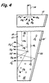
- Figure 4 which shows scattering particles 17c within the volume of the wedge 12.
- the scattered light rays are shown as groups 19a...19c which are composed of individual rays 19a...19n that are emitted from optical fiber 14 at rectangular edge 13.
- These particles may be passive or inert types mixed with the thermoplastic material and allowed to gradually settle toward the apex end of the wedge before curing the plastic thereby producing the increasing density of such light scattering centers as generally illustrated.
- the particles could be encapsulated liquid crystals such as those described in U.S. Patents No. 4,435,047 and No. 4,616,903 to Fergason and produced by Taliq Corp. of Sunnyvale, California.
- Transparent electrodes 21 and 21′ are applied over the front and back surfaces 18 and 20, respectively, of the wedge 12 for the purpose of applying an electric field.
- the application of an electric field has the effect of aligning the liquid crystals parallel to the direction of the field, in contrast to its normally structurally distorted shape in the absence of a field.
- the liquid crystals become more transparent, as their transparency is a function of the strength of the electric field. If the liquid crystals are nonuniformly distributed through the volume of the wedge, the application of a uniform electric field across the volume controls the light scattering effect desired.
- the use of encapsulated liquid crystals allows for some flexibility of manufacture.
- the encapsulated liquid crystals may be uniformly distributed within the volume of the wedge 12 and a nonuniform electric field applied across the wedge to produce the effect of an increasing density of light scattering centers.
- the electric field applied across the envelope the illuminating light emitted from the front surface 18 of the wedge 12 may be made more or less uniform as desired by the application.
- the applique When the illuminating device according to the invention is used to illuminate, for example, an applique (cutout decoration fastened to a larger piece of material) on the rear deck of a car, the applique may be formed by molding plastic such that the back surface forms a series of wedges relative to the front surface and such that each wedge may be illuminated by means of fiber optics at the thick end or edge of the wedge.
- the back surface is roughened and coated with the previously discussed diffuse reflector so that all of the light not absorbed by the back surface is reflected by the back surface and comes through the front surface 18 of the applique.
- the purpose of the wedge shape is to provide illumination through the front surface 18 which is as uniform as possible.
- the applique be reflective it may be made in two layers, the outer layer of which is provided with the usual corner cube reflective surface on the back, while the second layer has the wedge construction as generally shown in Figure 1.
- the source of light into the fibers may be a discharge lamp light source centrally located with the reflector or a similar high efficiency light source.
- a discharge lamp may be mounted on the deck lid without fear of high acceleration, since there is no filament to fail.
- the light beam introduced into the plastic wedge 12 is the nature of the light beam introduced into the plastic wedge 12. Generally, it is preferred that the light beam be collimated, or nearly so, to achieve the best uniformity of illuminating light emitted from the front surface 18 of the wedge. Secondly, the thickness and the angle of the wedge should be determined for the specific application. And finally, when used, a decision must be made on the location and distribution of light scattering centers, either over the emitting surface 18 or within the volume of the wedge 12.
- FIGS 5 and 6 A practical example of the invention is shown in Figures 5 and 6 which illustrate a double wedge illuminating device 22 fabricated to illuminate an automobile speedometer.
- the speedometer itself was fabricated using LCD technology, and the double wedge structure was used to backlight the LCD.
- light is collected and concentrated from a high efficiency light source (not shown) as before.
- the concentrated light is focused as an input to a pair of light guides 24 which transmit light, shown in Figure 5 as rays 25a...25n, into edges 28 and 30 of the double wedge 26.
- the edge 28 is comprised of portions 28A, 28B, 28C and 28D
- edge 30 is comprised of portions 30A, 30B, 30C and 30D.
- the double wedge shape is best seen in Figure 6 in which the two wedge portions 26 are joined at a common edge 33.
- the illuminator 22 having the back (32) and front (34) surfaces of each wedge 26 converge and the front surfaces 34 of the two wedges 26 forming a common illuminating surface conforming to a surface that is to be illuminated.
- the expanding beams of light 25a...25n are intercepted by serrated edge portions 28A...30D which reflect the light rays toward the thinner central part of the double wedge 26.
- the surfaces of the serrated edges 28 and 30 are coated with a specular reflector, such as sputtered aluminum.
- the serrations are designed such that the light beams 25a...25n are divided into seven parts of roughly equal lumens.
- the seven distributed light beams of the serrated edges 28 and 30 are reflected by the back surface 32 ( Figure 5) of the double wedge and are emitted from the front surface 34 ( Figure 6) in the same manner as the generalized structure shown in Figure 1.
- Figure 7 shows in more detail the back surface 32 of the double wedge 26 shown in Figure 6.
- the back surface may be grooved by means of grooves 17A, discussed with regards to Figure 3A, perpendicular to the direction from which the light (shown by rays 25a and 25n) is propagated from so am to form a surface that is stepped with 45° risers 36.
- the risers 36 intercept light rays 25a and 25n and redirect the light through the front surface 34 into groups of light rays 27.
- An alternative to grooving (17A) the back surface 32 is to texture the front surface 34 by simple rough sanding. The purpose of the sanding is to defeat total internal reflection and scatter the light striking this surface thereby allowing the light to escape.
- the entire plastic form of wedge 22 is coated with a diffuse reflective coating 38 to assure that any light which is not totally internally reflected is returned to the plastic cavity of wedge 22 and contributes to the output of wedge 22.
Description
- The present invention generally relates to the illumination of large surfaces and, more particularly, to providing uniform illumination over large areas at a shallow depth which is particularly suited for automobiles.
- In modern industrial design, there are a number of applications which call for illuminating large surface areas but the distance perpendicular to the surface area to be illuminated which is available for a light source is small. The problem then is to provide uniform illumination of a thin panel at an acceptable cost.
- In one such application, automobile manufacturers have been adding large decorative reflectorized areas on the rear deck lids of some of their models. The reflectorized areas blend in well with the rear lighting on the quarter panels and have a pleasing appearance during the day. At night, however, these areas appear dark and unattractive. To light these large areas with incandescent lamps presents two problems. First, it is difficult to get even illumination over such a large area using point sources such as incandescent lamps. Secondly, the large accelerations experienced by lamps mounted on the rear deck lid when it is closed are sufficient to deform or even fracture the filament of the lamp. Light emitting diode (LEDs) may very well serve as an alternative light source so as to solve such incandescent lamp problems.
- In another application, liquid crystal displays (LCDs) are commonly used for a variety of applications ranging from personal televisions to computer displays. One of the principal reasons for the popularity of LCDs is their small size and low power consumption. Current illuminators for LCDs use fluorescent lamps of high efficiency and light box cavities to provide uniform illumination. To make LCDs more acceptable, the LCDs are now generally provided with a source of back lighting. In order to retain the advantage of LCDs being used as a thin flat panel display, this back lighting source must also be thin. This type of design must be of a certain minimum thickness due to the lamp size and light box cavity size to achieve a uniform backlighting of the display.
- Another type of illuminator which achieves uniform illumination over a large area and yet is thin is manufactured by Lumitex, Inc. The Lumitex device uses a high efficiency light source and collects and concentrates this light by focusing it into an optical fiber bundle. The fibers of the bundle are fanned out and woven into a flat panel. Light is made to leak from the woven panel by sharp bending of the fibers in the weave pattern. The disadvantages of this device are its cost of construction and the lack of directionality of the leaked light and efficiency when designed to achieve a high degree of uniformity.
- US-A-4 466 697 proposes an optical fibre which is doped in the core region with refractive and/or reflective light scattering particles so that the fibre emits light along its length.
- US-A-4 528 617 discloses an illuminator for large surface areas comprising: a transparent wedge having back and front surfaces and a generally rectangular shaped edge between said surfaces, said front surface being co-extensive with an area to be illuminated; a light source; and at least one light guide optically coupling light from said light source to said rectangular shaped edge so that light entering the wedge is internally reflected from the back surface and emitted from said front surface.
- In one version of the illuminator two such wedges are adjoined along a common edge.
- It is therefore a general object of the present invention to provide a device that provides uniform illumination over a large area of shallow depth.
- It is another object of the invention to provide a thin, efficient and uniform illuminator for large areas.
- It is a further object of the invention to provide an efficient means to collect and conduct light from a high efficiency light source and uniformly distribute and emit this light over a large area.
- According to one aspect of the invention, there is provided an illuminator for large surface areas comprising: a transparent wedge having back and front surfaces and a generally rectangular shaped edge between said surfaces, said front surface being co-extensive with an area to be illuminated; a high efficiency light source; at least one light guide optically coupling light from said light source to said rectangular shaped edge so that light entering the wedge is internally reflected from the back surface and emitted from said front surface; characterized by said wedge being provided with scattering centers throughout its volume and said scattering centers being encapsulated liquid crystals and further comprising means for applying an electric field across said front and back surfaces of said wedge.
- According to another aspect of the invention, there is provided an illuminator for large surface areas comprising: a transparent wedge having back and front surfaces and a generally rectangularly shaped edge between said surfaces, said front surface being co-extensive with an area to be illuminated; a high efficiency light source; at least one light guide optically coupling light from said light source to said rectangular shaped edge so that light entering the wedge is internally reflected from the back surface and emitted from said front surface, characterized by said transparent wedge being provided with scattering centers in its volume, and the number of scattering centers increasing along a distance moving away from said rectangular shaped edge.
- According to a further aspect of the invention, there is provided an illuminator for large surface areas comprising: at least first and second transparent wedges each having back and front surfaces and a generally rectangular shaped edge between said surfaces, said front surface being co-extensive with an area to be illuminated; said wedges being joined along a common edge; a high efficiency light source; at least one light guide optically coupling light from said light source to at least one of said rectangular shaped edges so that light entering at least one of the wedges is internally reflected from the back surface and emitted from said front surface; and characterized by each of said transparent wedges being provided with scattering centers throughout its volume, the number of scattering centers increasing toward the said common edge.
- The foregoing and other objects, aspects and advantages will be better understood from the following detailed description of a preferred embodiment of the invention with reference to the drawings, in which:
- Figure 1 is an isometric drawing of the basic wedge shaped illuminating device according to the invention;
- Figure 2 is an enlarged cross-sectional view of the wedge shaped illuminating device shown in Figure 1 illustrating the internal reflections of light within the device;
- Figures 3A and 3B are enlarged portions of the light emitting surface of the wedge shaped illuminating device showing scattering centers on the surface;
- Figure 4 is an enlarged cross-sectional view of the wedge shaped illuminating device showing scattering centers in the volume of the wedge;
- Figure 5 is a top view of a double wedge embodiment of the invention;
- Figure 6 is an end view of the double wedge embodiment shown in Figure 5; and
- Figure 7 is an enlarged cross-sectional view of the double wedge embodiment shown in Figures 5 and 6 illustrating the internal reflections of light within the device.
- Referring now to the drawings, and more particularly to Figure 1, there is shown a basic form of the
illuminating device 10 according to the invention. The illuminating device includes a transparentplastic wedge 12. The wedge may be made of a moldable thermoplastic such as, for example, acrylics, polycarbonates or polystyrenes. Along arectangular edge 13 of thewedge 12 are a plurality ofoptical fibers 14. Theoptical fibers 14 terminate in a common bundle which is positioned to collect concentrated light from ahigh efficiency source 16 which may be, for example, an arc lamp centrally located in a reflector preferably having a spherical shape. The coupling between the ends of thefibers 14 and thewedge 12 may be made by melting them together or mated in some other way so as to reduce any reflection losses and which provides for the light from the fibers to spread out in a direction perpendicular to the direction of the beam so as to provide uniform illumination over the front orlight emitting surface 18. For the various applications ofdevice 10, thefront surface 18 is arranged to be co-extensive with the area to be illuminated. Theback surface 20, shown in more detail in Figure 2, of the wedge is coated with a reflecting coating. Preferably, this reflecting coating is a diffuse reflector such as Barium Sulfate, BaS0₄, as manufactured by Kodak of Rochester, New York, for this purpose. Alternatively, the reflecting coating may be a specular reflector, such as sputtered aluminum, but this generally does not produce as good a result as a diffuse reflector. - Figure 2 illustrates the reflections of light from one of the
optical fibers 14 located at therectangular edge 13 within the volume of thewedge 12. Figure 2 illustrates theback surface 20 in a different manner than it was shown in Figure 1 in thatback surface 20 now converges relative to thelight emitting surface 18. The challenge in illuminating a large area represented byilluminating device 18 is to make the illumination fairly uniform. To accomplish this by the practice of the present invention using edge lighting techniques, two principles are combined. First, thewedge 12 increases the angle of the reflections per unit distance as the wedge gets thinner and the back or reflectingsurface 20 intercepts more of the light beam, shown asrays 19a,...19n emitted fromfiber 14 located atsurface 13, as such a beam travels toward the apex of the wedge. Second, the number of scattering centers, related to thelight emitting surface 18, which send light off in all directions as shown by groups ofrays 19a...19n being emitted fromsurface 18. The scattering effect increases in the direction away from thesource 14. The reflector or reflective coating on theback surface 20 ensures that all of the light not absorbed by the reflector is reflected by the reflector and comes out through thefront surface 18. Either principle by itself provides some improvement in uniformity so that in some applications, only one or the other might be used. - The scattering sources may be formed on the
front surface 18, by scratching or grooving or coating thesurface 18, where the density of scattering sources is low near thesource 14 of the light and increases as the distance from the source increases. The scattering sources are illustrated in Figures 3A and 3B which show, respectively, grooves 17A and pits 17B as scattering sources which preferably increase in frequency of occurrence or density over the surface as their location moves away from the source ofillumination 14 located atrectangular edge 13. - Alternatively, the scattering sources may be formed within the volume of the material, again with the guideline that the related density increases as the distance from the source increases. This is illustrated in Figure 4 which shows scattering particles 17c within the volume of the
wedge 12. The scattered light rays are shown asgroups 19a...19c which are composed ofindividual rays 19a...19n that are emitted fromoptical fiber 14 atrectangular edge 13. These particles may be passive or inert types mixed with the thermoplastic material and allowed to gradually settle toward the apex end of the wedge before curing the plastic thereby producing the increasing density of such light scattering centers as generally illustrated. The particles could be encapsulated liquid crystals such as those described in U.S. Patents No. 4,435,047 and No. 4,616,903 to Fergason and produced by Taliq Corp. of Sunnyvale, California. -
Transparent electrodes back surfaces wedge 12 for the purpose of applying an electric field. The application of an electric field has the effect of aligning the liquid crystals parallel to the direction of the field, in contrast to its normally structurally distorted shape in the absence of a field. When an electric field is present, the liquid crystals become more transparent, as their transparency is a function of the strength of the electric field. If the liquid crystals are nonuniformly distributed through the volume of the wedge, the application of a uniform electric field across the volume controls the light scattering effect desired. On the other hand, the use of encapsulated liquid crystals allows for some flexibility of manufacture. Specifically, the encapsulated liquid crystals may be uniformly distributed within the volume of thewedge 12 and a nonuniform electric field applied across the wedge to produce the effect of an increasing density of light scattering centers. In other words, by appropriately selecting the electric field applied across the envelope, the illuminating light emitted from thefront surface 18 of thewedge 12 may be made more or less uniform as desired by the application. - When the illuminating device according to the invention is used to illuminate, for example, an applique (cutout decoration fastened to a larger piece of material) on the rear deck of a car, the applique may be formed by molding plastic such that the back surface forms a series of wedges relative to the front surface and such that each wedge may be illuminated by means of fiber optics at the thick end or edge of the wedge. The back surface is roughened and coated with the previously discussed diffuse reflector so that all of the light not absorbed by the back surface is reflected by the back surface and comes through the
front surface 18 of the applique. The purpose of the wedge shape is to provide illumination through thefront surface 18 which is as uniform as possible. If it is desired that the applique be reflective, it may be made in two layers, the outer layer of which is provided with the usual corner cube reflective surface on the back, while the second layer has the wedge construction as generally shown in Figure 1. - For very large areas, such as the back of a car, it may be necessary to have a series of illuminators, each fed by its own source, for example the end of an optical fiber. As mentioned and as shown in Figure 1 with regard to
reference number 16, the source of light into the fibers may be a discharge lamp light source centrally located with the reflector or a similar high efficiency light source. Unlike the incandescent lamp discussed previously, such discharge lamp may be mounted on the deck lid without fear of high acceleration, since there is no filament to fail. - It will be appreciated by those skilled in the art that there are several variables that must be considered in the practice of the invention. The first of these is the nature of the light beam introduced into the
plastic wedge 12. Generally, it is preferred that the light beam be collimated, or nearly so, to achieve the best uniformity of illuminating light emitted from thefront surface 18 of the wedge. Secondly, the thickness and the angle of the wedge should be determined for the specific application. And finally, when used, a decision must be made on the location and distribution of light scattering centers, either over the emittingsurface 18 or within the volume of thewedge 12. - A practical example of the invention is shown in Figures 5 and 6 which illustrate a double wedge illuminating device 22 fabricated to illuminate an automobile speedometer. The speedometer itself was fabricated using LCD technology, and the double wedge structure was used to backlight the LCD. In the embodiment shown in Figures 5 and 6, light is collected and concentrated from a high efficiency light source (not shown) as before. The concentrated light is focused as an input to a pair of light guides 24 which transmit light, shown in Figure 5 as
rays 25a...25n, intoedges 28 and 30 of thedouble wedge 26. The edge 28 is comprised ofportions 28A, 28B, 28C and 28D, whereas,edge 30 is comprised of portions 30A, 30B, 30C and 30D. The double wedge shape is best seen in Figure 6 in which the twowedge portions 26 are joined at acommon edge 33. The illuminator 22 having the back (32) and front (34) surfaces of eachwedge 26 converge and thefront surfaces 34 of the twowedges 26 forming a common illuminating surface conforming to a surface that is to be illuminated. As shown in Figure 5, the expanding beams of light 25a...25n are intercepted by serrated edge portions 28A...30D which reflect the light rays toward the thinner central part of thedouble wedge 26. The surfaces of theserrated edges 28 and 30 are coated with a specular reflector, such as sputtered aluminum. In the illustrated embodiment, the serrations are designed such that thelight beams 25a...25n are divided into seven parts of roughly equal lumens. The seven distributed light beams of theserrated edges 28 and 30 are reflected by the back surface 32 (Figure 5) of the double wedge and are emitted from the front surface 34 (Figure 6) in the same manner as the generalized structure shown in Figure 1. - Figure 7 shows in more detail the
back surface 32 of thedouble wedge 26 shown in Figure 6. The back surface may be grooved by means of grooves 17A, discussed with regards to Figure 3A, perpendicular to the direction from which the light (shown byrays risers 36. Therisers 36intercept light rays front surface 34 into groups oflight rays 27. An alternative to grooving (17A) theback surface 32 is to texture thefront surface 34 by simple rough sanding. The purpose of the sanding is to defeat total internal reflection and scatter the light striking this surface thereby allowing the light to escape. Except for the desired illuminatingsurface 34, the entire plastic form of wedge 22 is coated with a diffusereflective coating 38 to assure that any light which is not totally internally reflected is returned to the plastic cavity of wedge 22 and contributes to the output of wedge 22. - While the embodiment shown in Figures 5 and 6 is particularly advantageous for use as a back light source for LCDs, such as the automobile speedometer mentioned, this particular embodiment of the invention may be used wherever uniform illumination of a large surface area is desired. Therefore, while the invention has been described in terms of preferred embodiments, those skilled in the art will recognize that the invention can be practised with various modifications.
Claims (15)
- An illuminator for large surface areas comprising:
a transparent wedge (12) having back (20) and front (18) surfaces and a generally rectangular shaped edge (13) between said surfaces, said front surface being co-extensive with an area to be illuminated;
a high efficiency light source (16);
at least one light guide (14) optically coupling light from said light source to said rectangular shaped edge so that light entering the wedge is internally reflected from the back surface (20) and emitted from said front surface (18); characterized by
said wedge being provided with scattering centers (17c) throughout its volume and said scattering centers being encapsulated liquid crystals and further comprising means (21,21′) for applying an electric field across said front and back surfaces of said wedge. - The illuminator according to claim 1 wherein said wedge (12) is of a plastic material.
- The illuminator as recited in claim 2 wherein said plastic is a thermoplastic and said light guide (14) is fused with said wedge (12) so as to reduce any reflection losses and cause light from said light guide to spread out within said plastic wedge.
- The illuminator as recited in claim 1, 2 or 3 wherein said front surface (18) is integrally formed with the surface area to be illuminated.
- An illuminator for large surface areas comprising:
a transparent wedge (12) having back (20) and front (18) surfaces and a generally rectangularly shaped edge (13) between said surfaces, said front surface (18) being co-extensive with an area to be illuminated;
a high efficiency light source (16);
at least one light guide (14) optically coupling light from said light source to said rectangular shaped edge (13) so that light entering the wedge is internally reflected from the back surface and emitted from said front surface, characterized by
said transparent wedge being provided with scattering centers (17abc) in its volume, and
the number of scattering centers increasing along a distance moving away from said rectangular shaped edge (13). - The illuminator as recited in claim 5 wherein said scattering centers are grooves (17a) formed in said volume perpendicular to a direction of propagation of the light within said wedge and having a frequency of occurrence which increases away from said rectangular shaped edge.
- The illuminator as recited in claim 5 wherein said scattering centers are pits (17b) formed in said volume and having a density which increases away from said rectangular shaped edge.
- The illuminator as recited in claim 5 wherein said scattering centers (17) are provided throughout the volume of the wedge (12).
- The illuminator as recited in claim 5 wherein said at least one light guide (24) is coupled to said wedge immediately adjacent and parallel to said rectangular edge and said rectangular edge is serrated (28a-d,30a-d) to reflect light from said light guide toward said back and front surfaces.
- The illuminator as recited in claim 5 wherein said back surface is grooved (17a) to form surfaces (36) perpendicular to the direction of light (25) propagating within said wedge whereby light (27) is reflected from said surfaces (36) toward said front surface.
- An illuminator (22) for large surface areas comprising:
at least first and second transparent wedges (26) each having back and front surfaces and a generally rectangular shaped edge between said surfaces, said front surface being co-extensive with an area to be illuminated;
said wedges being joined along a common edge;
a high efficiency light source (16);
at least one light guide (24) optically coupling light from said light source to at least one of said rectangular shaped edges (28) so that light entering at least one of the wedges is internally reflected from the back surface and emitted from said front surface; and characterized by
each of said transparent wedges being provided with scattering centers (17c) throughout its volume, the number of scattering centers (17c) increasing toward the said common edge. - The illuminator as recited in claim 11 wherein the number of wedges is at least two and said wedges are joined along a common edge where said back and front surfaces of each wedge converge and the front surfaces of said wedges form a common illuminating surface conforming to a surface area to be illuminated.
- The illuminator as recited in claim 11 wherein there is at least one light guide (24) for each of said wedges, and each light guide is coupled to a corresponding one of said plastic wedges immediately adjacent and parallel to the rectangular edge of that wedge and said rectangular edge is serrated (28,30) to reflect light from said light guide toward said converging back and front surfaces.
- The illuminator as recited in any one of claims 1 to 13 further comprising a reflective coating (38) applied to said back surface or surfaces.
- The illuminator as recited in claim 14 wherein said reflective coating (38) is of a diffuse type.
Applications Claiming Priority (2)
| Application Number | Priority Date | Filing Date | Title |
|---|---|---|---|
| US07/496,485 US5101325A (en) | 1990-03-20 | 1990-03-20 | Uniform illumination of large, thin surfaces particularly suited for automotive applications |
| US496485 | 1990-03-20 |
Publications (2)
| Publication Number | Publication Date |
|---|---|
| EP0453092A1 EP0453092A1 (en) | 1991-10-23 |
| EP0453092B1 true EP0453092B1 (en) | 1994-08-17 |
Family
ID=23972848
Family Applications (1)
| Application Number | Title | Priority Date | Filing Date |
|---|---|---|---|
| EP91302247A Expired - Lifetime EP0453092B1 (en) | 1990-03-20 | 1991-03-15 | Uniform illumination of large, thin surfaces particularly suited for automotive applications |
Country Status (5)
| Country | Link |
|---|---|
| US (1) | US5101325A (en) |
| EP (1) | EP0453092B1 (en) |
| JP (1) | JPH07120485B2 (en) |
| CA (1) | CA2034378C (en) |
| DE (1) | DE69103456T2 (en) |
Cited By (7)
| Publication number | Priority date | Publication date | Assignee | Title |
|---|---|---|---|---|
| US7357548B2 (en) | 2003-09-08 | 2008-04-15 | Koninklijke Philips Electronics, N.V. | Light-guiding system comprising a number of light transmission rods |
| CN103153702A (en) * | 2010-07-30 | 2013-06-12 | 汽车照明后灯法国有限公司 | Signalling lamps for motor vehicle |
| US10597097B2 (en) | 2015-09-07 | 2020-03-24 | Sabic Global Technologies B.V. | Aerodynamic features of plastic glazing of tailgates |
| US10690314B2 (en) | 2015-09-07 | 2020-06-23 | Sabic Global Technologies B.V. | Lighting systems of tailgates with plastic glazing |
| US10717348B2 (en) | 2015-09-07 | 2020-07-21 | Sabic Global Technologies B.V. | Surfaces of plastic glazing of tailgates |
| US11267173B2 (en) | 2015-09-07 | 2022-03-08 | Sabic Global Technologies B.V. | Molding of plastic glazing of tailgates |
| US11466834B2 (en) | 2015-11-23 | 2022-10-11 | Sabic Global Technologies B.V. | Lighting systems for windows having plastic glazing |
Families Citing this family (89)
| Publication number | Priority date | Publication date | Assignee | Title |
|---|---|---|---|---|
| US5186530A (en) * | 1991-11-22 | 1993-02-16 | Tir Systems, Ltd. | Lighting structure having variable transmissivity internal light guide illumination |
| US5249077A (en) * | 1991-12-12 | 1993-09-28 | Microvideo Instruments, Inc. | Darkfield illuminator for a microscope slide |
| US5203625A (en) * | 1992-01-06 | 1993-04-20 | Daniel Naum | Diffusion system |
| US6002829A (en) * | 1992-03-23 | 1999-12-14 | Minnesota Mining And Manufacturing Company | Luminaire device |
| US5237641A (en) * | 1992-03-23 | 1993-08-17 | Nioptics Corporation | Tapered multilayer luminaire devices |
| US5303322A (en) * | 1992-03-23 | 1994-04-12 | Nioptics Corporation | Tapered multilayer luminaire devices |
| US5528720A (en) * | 1992-03-23 | 1996-06-18 | Minnesota Mining And Manufacturing Co. | Tapered multilayer luminaire devices |
| EP0644742B1 (en) * | 1992-06-12 | 1999-12-08 | Miravant Systems, Inc. | Diffusor tip for an optical fiber |
| FR2694069B1 (en) * | 1992-07-27 | 1994-11-04 | Francois Parmentier | Distributed lighting device. |
| JPH06130385A (en) * | 1992-10-16 | 1994-05-13 | Mitsubishi Electric Corp | Surface light emitting device |
| US5257168A (en) * | 1992-11-30 | 1993-10-26 | General Electric Company | Projection headlamp lighting system using a light conductor having stepped termination |
| US5988826A (en) * | 1993-03-25 | 1999-11-23 | Enplas Corporation | Surface light source device |
| AU4263793A (en) * | 1993-04-22 | 1994-11-08 | Francois Parmentier | Distributed lighting device |
| US5465193A (en) * | 1993-06-28 | 1995-11-07 | Motorola, Inc. | Front light guide for liquid crystal device with stairstep element which emits light |
| JP3781441B2 (en) * | 1993-07-23 | 2006-05-31 | 康博 小池 | Light scattering light guide light source device and liquid crystal display device |
| FR2716954B1 (en) * | 1994-03-07 | 1996-04-19 | Claude Goumy | Fiber optic lighting device with transparent or translucent volumes. |
| US5682213A (en) * | 1994-07-01 | 1997-10-28 | Adaptive Optics Associates, Inc. | Optical illuminator for liquid crystal displays |
| US6104452A (en) * | 1994-07-01 | 2000-08-15 | Adaptive Optics Associates, Inc. | Optical illuminator for liquid crystal displays |
| JP3334833B2 (en) * | 1995-08-24 | 2002-10-15 | 松下電器産業株式会社 | Linear lighting device |
| EP0703405A1 (en) * | 1994-09-21 | 1996-03-27 | Siemens Aktiengesellschaft | Fiber optics illumination system |
| JP3187280B2 (en) * | 1995-05-23 | 2001-07-11 | シャープ株式会社 | Surface lighting device |
| DE29508596U1 (en) * | 1995-05-30 | 1995-08-17 | Sauernheimer Helmut | Lighting arrangement for a translucent motif or information carrier |
| US7108414B2 (en) | 1995-06-27 | 2006-09-19 | Solid State Opto Limited | Light emitting panel assemblies |
| US6712481B2 (en) | 1995-06-27 | 2004-03-30 | Solid State Opto Limited | Light emitting panel assemblies |
| US5613751A (en) * | 1995-06-27 | 1997-03-25 | Lumitex, Inc. | Light emitting panel assemblies |
| DE19547861A1 (en) * | 1995-12-21 | 1997-06-26 | Reitter & Schefenacker Gmbh | Rear light for vehicles, preferably motor vehicles |
| US5895115A (en) | 1996-01-16 | 1999-04-20 | Lumitex, Inc. | Light emitting panel assemblies for use in automotive applications and the like |
| US5839813A (en) * | 1996-10-02 | 1998-11-24 | Delco Electronics Corporation | Thin rear combination lamp system |
| EP1666935A1 (en) | 1996-10-25 | 2006-06-07 | Omron Corporation | Surface light source device and liquid crystal display device, portable telephone and information terminal using surface light source device |
| JP4163259B2 (en) * | 1997-01-13 | 2008-10-08 | ミネソタ・マイニング・アンド・マニュファクチャリング・カンパニー | Lighting device |
| JPH10208528A (en) * | 1997-01-28 | 1998-08-07 | Hitachi Chem Co Ltd | Lighting system |
| US5791757A (en) * | 1997-04-01 | 1998-08-11 | Ford Global Technologies, Inc. | Vehicle lighting system utilizing a uniform thickness thin sheet optical element |
| US6031958A (en) | 1997-05-21 | 2000-02-29 | Mcgaffigan; Thomas H. | Optical light pipes with laser light appearance |
| WO1998053348A1 (en) * | 1997-05-21 | 1998-11-26 | Mcgaffigan Thomas H | Optical light pipes with laser light appearance |
| JP3545237B2 (en) * | 1998-02-19 | 2004-07-21 | 三洋電機株式会社 | Liquid crystal display device with light collecting mechanism |
| JPH11283408A (en) * | 1998-03-27 | 1999-10-15 | Hitachi Chem Co Ltd | Lighting system |
| US6621520B1 (en) * | 1998-06-09 | 2003-09-16 | Pentax Corporation | Display unit of digital camera |
| US6241919B1 (en) * | 1998-08-07 | 2001-06-05 | Chin-Piao Kuo | Casting polymerization for producing light guide of LCD |
| DE69942499D1 (en) * | 1998-10-05 | 2010-07-29 | Semiconductor Energy Lab | Reflecting semiconductor device |
| WO2000042456A1 (en) * | 1999-01-14 | 2000-07-20 | Federal-Mogul Corporation | Waveguide assembly for laterally-directed illumination in a vehicle lighting system |
| US6752505B2 (en) | 1999-02-23 | 2004-06-22 | Solid State Opto Limited | Light redirecting films and film systems |
| US7364341B2 (en) | 1999-02-23 | 2008-04-29 | Solid State Opto Limited | Light redirecting films including non-interlockable optical elements |
| US6305813B1 (en) | 1999-08-11 | 2001-10-23 | North American Lighting, Inc. | Display device using a light guide for exterior automotive lighting |
| TW461533U (en) * | 2000-05-11 | 2001-10-21 | Asustek Comp Inc | Status display device of notebook computer |
| US20050007515A1 (en) * | 2000-06-26 | 2005-01-13 | Faris Sadeg M. | Backlight for a liquid crystal display having high light-recycling efficiency |
| DE10123263B4 (en) * | 2001-05-12 | 2005-12-08 | Daimlerchrysler Ag | Light guide system for the interior of a motor vehicle |
| KR100394170B1 (en) * | 2001-06-23 | 2003-08-09 | 송영윤 | An Lighting Device Using Cable Optics |
| JP2003086016A (en) * | 2001-09-07 | 2003-03-20 | Rohm Co Ltd | Lighting system, liquid crystal display system and light guiding plate |
| GB0123815D0 (en) | 2001-10-03 | 2001-11-21 | 3M Innovative Properties Co | Light-guide lights providing a substantially monochromatic beam |
| US6690349B2 (en) * | 2001-11-09 | 2004-02-10 | Koninklijke Philips Electronics N.V. | Scrolling backlight system for LCD TV |
| ATE435779T1 (en) * | 2001-11-19 | 2009-07-15 | Uwe Braun Gmbh | OPTICAL GLARE REDUCER |
| DE60236538D1 (en) * | 2001-12-05 | 2010-07-08 | Rambus Int Ltd | TRANSFECTOR, TRANSFECTOR SYSTEMS AND INDICATORS UN |
| US6874922B2 (en) * | 2001-12-13 | 2005-04-05 | Toyoda Gosei Co., Ltd. | Illumination device |
| US6796700B2 (en) * | 2002-02-02 | 2004-09-28 | Edward Robert Kraft | Flat panel luminaire with remote light source and hollow light pipe for back lit signage applications |
| US6908204B2 (en) * | 2002-02-02 | 2005-06-21 | Edward Robert Kraft | Flat panel luminaire having embedded light guides |
| SE522171C2 (en) * | 2002-05-17 | 2004-01-20 | Aron Losonczi | Building blocks comprising light-permeable fibers and method of making the same |
| GB2392488B (en) * | 2002-08-29 | 2006-09-20 | Telectra Ltd | Illumination device |
| KR100542058B1 (en) * | 2002-12-06 | 2006-01-11 | 주식회사 에스엘 엘씨디 | Lamp for vehicle |
| EP1651918B1 (en) * | 2003-07-24 | 2012-12-19 | Eisenmann AG | Device for hardening a coating of an object, which is made of a material hardening under electromagnetic radiation, especially a uv lacquer or a thermally hardening lacquer |
| WO2005024475A1 (en) * | 2003-09-08 | 2005-03-17 | Koninklijke Philips Electronics N.V. | A light-guiding system comprising a plate-like triangular guiding member |
| KR20060071413A (en) * | 2003-09-08 | 2006-06-26 | 코닌클리즈케 필립스 일렉트로닉스 엔.브이. | A light-guiding system comprising a plate-like light-emitting element |
| US7140763B1 (en) * | 2004-02-06 | 2006-11-28 | Keith-Wolfe Carol I | Light distribution system |
| TWI270721B (en) * | 2004-12-03 | 2007-01-11 | Innolux Display Corp | Light guide plate and method of manufacturing the same |
| KR20070098953A (en) * | 2005-01-28 | 2007-10-05 | 코닌클리즈케 필립스 일렉트로닉스 엔.브이. | Headlamp for vehicles |
| AT502243B1 (en) * | 2005-03-11 | 2007-08-15 | Schoenberg Elumic Gmbh | SELF-LIGHTING DISPLAY PANEL |
| DE102005036869A1 (en) * | 2005-08-02 | 2007-02-08 | Tilmann Krieg | Multilayer connected structure for covering interiors or exteriors of buildings has transparent rigid layer with connected light conductive fibers joined to an external light source |
| US7284886B2 (en) * | 2005-11-23 | 2007-10-23 | Volkswagen Ag | Moonroof for a motor vehicle |
| JP4709230B2 (en) * | 2006-01-23 | 2011-06-22 | 富士フイルム株式会社 | Surface lighting device |
| EP1832902A1 (en) * | 2006-03-10 | 2007-09-12 | Delphi Technologies, Inc. | Flat lamp device |
| US7575342B2 (en) * | 2006-05-25 | 2009-08-18 | Chunghwa Picture Tubes, Ltd. | Liquid crystal display and backlight module including tilted lamp tubes |
| US7997781B2 (en) * | 2006-05-25 | 2011-08-16 | I2Ic Corporation | Energy efficient illumination for a light source in the form of a surface |
| TWI341934B (en) * | 2006-06-28 | 2011-05-11 | Lg Display Co Ltd | Backlight unit using optical fibers |
| JP2011503771A (en) * | 2007-07-05 | 2011-01-27 | カナデ,ウダヤン | Light source with variable thickness |
| JP4975136B2 (en) * | 2010-04-13 | 2012-07-11 | シャープ株式会社 | Lighting device |
| FR2978395B1 (en) * | 2011-07-27 | 2013-08-09 | Automotive Lighting Rear Lamps France | SIGNALING LIGHT FOR MOTOR VEHICLE |
| FR2963292B1 (en) * | 2010-07-30 | 2013-04-12 | Automotive Lighting Rear Lamps France | FIRE FOR TRUNK DOOR OR TAIL OF MOTOR VEHICLE |
| EP2466349A1 (en) * | 2010-12-17 | 2012-06-20 | 3M Innovative Properties Company | Light guide illumination device with fibrous diffuser layer |
| US8787717B2 (en) | 2011-04-26 | 2014-07-22 | Corning Incorporated | Systems and methods for coupling light into a transparent sheet |
| US8724942B2 (en) | 2011-04-26 | 2014-05-13 | Corning Incorporated | Light-coupling optical systems and methods employing light-diffusing optical fiber |
| KR101393346B1 (en) * | 2012-03-19 | 2014-05-09 | 현대모비스 주식회사 | Lamp apparatus for an automobile |
| JP6203519B2 (en) * | 2012-09-13 | 2017-09-27 | 株式会社小糸製作所 | Vehicle lighting |
| US8840294B2 (en) * | 2012-11-12 | 2014-09-23 | Shenzhen China Star Optoelectronics Technology Co., Ltd | Sidelight backlight module with assisting solar light source and liquid crystal display device |
| EP2787276A1 (en) * | 2013-04-05 | 2014-10-08 | Flextronics Automotive GmbH & Co. KG | Fibre optic assembly having two fibre optic elements |
| TW201441073A (en) * | 2013-04-26 | 2014-11-01 | Hon Hai Prec Ind Co Ltd | LED vehicle lamp |
| CN104570194A (en) * | 2014-12-31 | 2015-04-29 | 深圳市华星光电技术有限公司 | Light guide plate and display module |
| US10443813B2 (en) * | 2016-04-07 | 2019-10-15 | Signify Holding B.V.. | Lens with slits |
| JP6933901B2 (en) * | 2017-01-23 | 2021-09-08 | スタンレー電気株式会社 | Vehicle lighting |
| US11119263B2 (en) * | 2017-06-22 | 2021-09-14 | Xerox Corporation | System and method for image specific illumination of image printed on optical waveguide |
| US11772546B2 (en) | 2021-11-18 | 2023-10-03 | Valeo North America, Inc. | Edge lighting for a continuous illumination appearance |
Family Cites Families (19)
| Publication number | Priority date | Publication date | Assignee | Title |
|---|---|---|---|---|
| US2347665A (en) * | 1941-03-04 | 1944-05-02 | Christensen Geneva Bandy | Internal reflection lighting means |
| GB664193A (en) * | 1949-02-26 | 1952-01-02 | Ilford Ltd | Photographic dark-room lamp |
| US2712593A (en) * | 1951-04-21 | 1955-07-05 | Bendix Aviat Corp | Edge illuminated dial |
| US3040168A (en) * | 1957-09-25 | 1962-06-19 | Kollsman Instr Corp | Instrument lighting device |
| DE2827573C2 (en) * | 1978-06-23 | 1983-02-03 | Blaupunkt-Werke Gmbh, 3200 Hildesheim | Large area light source |
| US4435047A (en) * | 1981-09-16 | 1984-03-06 | Manchester R & D Partnership | Encapsulated liquid crystal and method |
| US4466697A (en) * | 1981-11-12 | 1984-08-21 | Maurice Daniel | Light dispersive optical lightpipes and method of making the same |
| US4528617A (en) * | 1982-02-08 | 1985-07-09 | Sheltered Workshop For The Disabled, Inc. | Light distribution apparatus |
| US4516834A (en) * | 1983-04-08 | 1985-05-14 | Rockwell International Corporation | Contrast enhanced liquid crystal display |
| US4637687A (en) * | 1984-06-14 | 1987-01-20 | General Electric Company | Cascaded, dual cell transflective liquid crystal display |
| EP0229863B1 (en) * | 1986-01-24 | 1991-10-30 | Franz Johnsen Vinther | An illuminated board |
| JPS62161203U (en) * | 1986-04-01 | 1987-10-14 | ||
| US4830899A (en) * | 1986-07-04 | 1989-05-16 | Nissen Chemical Industry Co., Ltd. | Light reflection material, its manufacture and application |
| US4693560A (en) * | 1986-09-25 | 1987-09-15 | Taliq Corporation | Double layer display |
| JPS6380593U (en) * | 1986-11-13 | 1988-05-27 | ||
| US4924612A (en) * | 1987-04-14 | 1990-05-15 | Kopelman Robert Z | Fiber optic sign |
| JP2749012B2 (en) * | 1987-08-28 | 1998-05-13 | 株式会社日立製作所 | Liquid crystal display |
| JPH0521205Y2 (en) * | 1988-07-14 | 1993-05-31 | ||
| JPH0239404U (en) * | 1988-09-07 | 1990-03-16 |
-
1990
- 1990-03-20 US US07/496,485 patent/US5101325A/en not_active Expired - Lifetime
-
1991
- 1991-01-17 CA CA002034378A patent/CA2034378C/en not_active Expired - Lifetime
- 1991-03-15 DE DE69103456T patent/DE69103456T2/en not_active Expired - Lifetime
- 1991-03-15 EP EP91302247A patent/EP0453092B1/en not_active Expired - Lifetime
- 1991-03-19 JP JP3078274A patent/JPH07120485B2/en not_active Expired - Fee Related
Cited By (11)
| Publication number | Priority date | Publication date | Assignee | Title |
|---|---|---|---|---|
| US7357548B2 (en) | 2003-09-08 | 2008-04-15 | Koninklijke Philips Electronics, N.V. | Light-guiding system comprising a number of light transmission rods |
| CN103153702A (en) * | 2010-07-30 | 2013-06-12 | 汽车照明后灯法国有限公司 | Signalling lamps for motor vehicle |
| US10597097B2 (en) | 2015-09-07 | 2020-03-24 | Sabic Global Technologies B.V. | Aerodynamic features of plastic glazing of tailgates |
| US10690314B2 (en) | 2015-09-07 | 2020-06-23 | Sabic Global Technologies B.V. | Lighting systems of tailgates with plastic glazing |
| US10717348B2 (en) | 2015-09-07 | 2020-07-21 | Sabic Global Technologies B.V. | Surfaces of plastic glazing of tailgates |
| US10948152B2 (en) | 2015-09-07 | 2021-03-16 | Sabic Global Technologies B.V. | Lighting systems of tailgates with plastic glazing |
| US11267173B2 (en) | 2015-09-07 | 2022-03-08 | Sabic Global Technologies B.V. | Molding of plastic glazing of tailgates |
| US11458709B2 (en) | 2015-09-07 | 2022-10-04 | Sabic Global Technologies B.V. | Three shot plastic tailgate |
| US11845240B2 (en) | 2015-09-07 | 2023-12-19 | Sabic Global Technologies B.V. | Three shot plastic tailgate |
| US11466834B2 (en) | 2015-11-23 | 2022-10-11 | Sabic Global Technologies B.V. | Lighting systems for windows having plastic glazing |
| US11766965B2 (en) | 2015-11-23 | 2023-09-26 | Sabic Global Technologies B.V. | Illuminated graphic in an automotive plastic glazing |
Also Published As
| Publication number | Publication date |
|---|---|
| DE69103456D1 (en) | 1994-09-22 |
| JPH04221236A (en) | 1992-08-11 |
| JPH07120485B2 (en) | 1995-12-20 |
| US5101325A (en) | 1992-03-31 |
| DE69103456T2 (en) | 1995-03-23 |
| EP0453092A1 (en) | 1991-10-23 |
| CA2034378C (en) | 1999-04-20 |
| CA2034378A1 (en) | 1991-09-21 |
Similar Documents
| Publication | Publication Date | Title |
|---|---|---|
| EP0453092B1 (en) | Uniform illumination of large, thin surfaces particularly suited for automotive applications | |
| US5926601A (en) | Stacked backlighting system using microprisms | |
| JP3379043B2 (en) | Planar lighting device | |
| JP2692025B2 (en) | Planar light emitter device | |
| KR101575877B1 (en) | Light guide plate and backlight unit having the same | |
| JP4001736B2 (en) | Surface light emitting device and liquid crystal display device | |
| US7052168B2 (en) | Illumination device | |
| US5485291A (en) | Uniformly thin, high efficiency large area lighting panel with two facet grooves that are spaced apart and have light source facing facets with smaller slopes than the facets facing away from the light source | |
| KR100587247B1 (en) | Surface light source device of side light type | |
| US7868970B2 (en) | Light guide plate, as well as a planar lighting device and liquid crystal display apparatus using the same | |
| US20080055931A1 (en) | Method and Systems for Illuminating | |
| US20060268581A1 (en) | Method and apparatus for light guide unit and backlight module using the same | |
| JP3549087B2 (en) | Light guide, side light type surface light source device and liquid crystal display device | |
| US20050175282A1 (en) | Light-guide lights suitable for use in illuminated displays | |
| JP2001035230A (en) | Flat lighting system | |
| WO1994023244A1 (en) | Flat thin uniform thickness large area light source | |
| EP1725809A2 (en) | Internally illuminated light panel with led modules having light redirecting devices | |
| TW454100B (en) | Light-source element with inclined light-coupling in side | |
| EP1336877A1 (en) | Surface-emitting device and liquid crystal display device | |
| CN107667255B (en) | Illumination system and illumination method using light guide | |
| KR20200138758A (en) | Wedge light guide | |
| KR100716741B1 (en) | Reflector for liquid crystal display device and back light unit thereof | |
| US7048399B2 (en) | Light guide plate and surface light source | |
| JP3023026B2 (en) | Surface lighting device | |
| JPS62169105A (en) | Planar light source |
Legal Events
| Date | Code | Title | Description |
|---|---|---|---|
| PUAI | Public reference made under article 153(3) epc to a published international application that has entered the european phase |
Free format text: ORIGINAL CODE: 0009012 |
|
| AK | Designated contracting states |
Kind code of ref document: A1 Designated state(s): DE FR GB NL |
|
| 17P | Request for examination filed |
Effective date: 19911220 |
|
| 17Q | First examination report despatched |
Effective date: 19930505 |
|
| GRAA | (expected) grant |
Free format text: ORIGINAL CODE: 0009210 |
|
| AK | Designated contracting states |
Kind code of ref document: B1 Designated state(s): DE FR GB NL |
|
| REF | Corresponds to: |
Ref document number: 69103456 Country of ref document: DE Date of ref document: 19940922 |
|
| ET | Fr: translation filed | ||
| PLBE | No opposition filed within time limit |
Free format text: ORIGINAL CODE: 0009261 |
|
| STAA | Information on the status of an ep patent application or granted ep patent |
Free format text: STATUS: NO OPPOSITION FILED WITHIN TIME LIMIT |
|
| 26N | No opposition filed | ||
| REG | Reference to a national code |
Ref country code: GB Ref legal event code: IF02 |
|
| PGFP | Annual fee paid to national office [announced via postgrant information from national office to epo] |
Ref country code: NL Payment date: 20030221 Year of fee payment: 13 |
|
| PG25 | Lapsed in a contracting state [announced via postgrant information from national office to epo] |
Ref country code: NL Free format text: LAPSE BECAUSE OF NON-PAYMENT OF DUE FEES Effective date: 20041001 |
|
| NLV4 | Nl: lapsed or anulled due to non-payment of the annual fee |
Effective date: 20041001 |
|
| PGFP | Annual fee paid to national office [announced via postgrant information from national office to epo] |
Ref country code: FR Payment date: 20100406 Year of fee payment: 20 |
|
| PGFP | Annual fee paid to national office [announced via postgrant information from national office to epo] |
Ref country code: GB Payment date: 20100326 Year of fee payment: 20 |
|
| PGFP | Annual fee paid to national office [announced via postgrant information from national office to epo] |
Ref country code: DE Payment date: 20100329 Year of fee payment: 20 |
|
| REG | Reference to a national code |
Ref country code: DE Ref legal event code: R071 Ref document number: 69103456 Country of ref document: DE |
|
| REG | Reference to a national code |
Ref country code: GB Ref legal event code: PE20 Expiry date: 20110314 |
|
| PG25 | Lapsed in a contracting state [announced via postgrant information from national office to epo] |
Ref country code: GB Free format text: LAPSE BECAUSE OF EXPIRATION OF PROTECTION Effective date: 20110314 |
|
| PG25 | Lapsed in a contracting state [announced via postgrant information from national office to epo] |
Ref country code: DE Free format text: LAPSE BECAUSE OF EXPIRATION OF PROTECTION Effective date: 20110315 |