EP0453213A2 - Reducing interference in R.F. signals - Google Patents
Reducing interference in R.F. signals Download PDFInfo
- Publication number
- EP0453213A2 EP0453213A2 EP91303308A EP91303308A EP0453213A2 EP 0453213 A2 EP0453213 A2 EP 0453213A2 EP 91303308 A EP91303308 A EP 91303308A EP 91303308 A EP91303308 A EP 91303308A EP 0453213 A2 EP0453213 A2 EP 0453213A2
- Authority
- EP
- European Patent Office
- Prior art keywords
- received signal
- channel
- response
- transmitted
- received
- Prior art date
- Legal status (The legal status is an assumption and is not a legal conclusion. Google has not performed a legal analysis and makes no representation as to the accuracy of the status listed.)
- Granted
Links
Images

Classifications
-
- H—ELECTRICITY
- H04—ELECTRIC COMMUNICATION TECHNIQUE
- H04B—TRANSMISSION
- H04B1/00—Details of transmission systems, not covered by a single one of groups H04B3/00 - H04B13/00; Details of transmission systems not characterised by the medium used for transmission
- H04B1/06—Receivers
- H04B1/10—Means associated with receiver for limiting or suppressing noise or interference
- H04B1/1027—Means associated with receiver for limiting or suppressing noise or interference assessing signal quality or detecting noise/interference for the received signal
- H04B1/1036—Means associated with receiver for limiting or suppressing noise or interference assessing signal quality or detecting noise/interference for the received signal with automatic suppression of narrow band noise or interference, e.g. by using tuneable notch filters
-
- H—ELECTRICITY
- H04—ELECTRIC COMMUNICATION TECHNIQUE
- H04B—TRANSMISSION
- H04B1/00—Details of transmission systems, not covered by a single one of groups H04B3/00 - H04B13/00; Details of transmission systems not characterised by the medium used for transmission
- H04B1/06—Receivers
- H04B1/10—Means associated with receiver for limiting or suppressing noise or interference
- H04B1/1027—Means associated with receiver for limiting or suppressing noise or interference assessing signal quality or detecting noise/interference for the received signal
Definitions
- This invention relates to devices for reducing in-band interference in r.f. received signals.
- Two of the main sources of interference in such signals is interference from other users and multi-path propagation.
- Multi-path propagation causes intersymbol interference on digital communication links. Intersymbol interference occurs because each bit of transmitted information arrives at the receiver several times spaced over a wide (of the order of 8 milliseconds) differential time interval. At 2.4 k/bits per second, each bit lasts 0.417 milliseconds, so the transmitted information becomes confused and corrupted at the receiver due to the multiple propagation paths.
- the first is channel equalisation, and this works by passing the received signal through a filter which has a response equivalent to the inverse of the channel through which the signal was received.
- a disadvantage of this type of system is that it is not always possible to produce such an inverse of channel.
- the other known technique for combating the problem is a channel estimator (e.g. WO-A-88/09591) which works by identifying the response of the channel, and the detection of the data takes place by comparing the received (distorted) data with a locally generated data stream that has been passed through a model of the channel.
- a channel estimator e.g. WO-A-88/09591
- the invention provides a device for reducing in-band interference in an r.f. received signal representing digital data, comprising means for filtering interfering signals from the received signal, and means for deciding the most likely digital data to have been transmitted by comparing the filtered received signal with locally generated signals processed in dependence on the estimated response of the communication channel.
- the device for reducing interference in an r.f. received signal is incorporated in a radio receiver 1 for receiving SSB transmissions, and comprises an interference rejection circuit 2 and a channel estimating demodulator 3, which receives digital data from an analogue-to-digital converter 4 which converts the audio output of the receiver 1 into digital form.
- FIG. 3 A spectrum of a typical audio output is shown in Figure 3.
- the two peaks represent interference e.g. formed by an interfering binary FSK transmission.
- the received signal is sampled and the corresponding spectrum is produced by spectrum analyser 5.
- the general shape of the spectrum of the received signal will of course be known and this enables the interference identification circuit 6 to generate a notional template T having the same general shape of spectrum as the transmitted signal.
- the frequency spectrum is divided into a number of equal sub-bands across the spectrum of the signal in circuit 6.
- the amplitude of the spectrum is assessed in each sub-band and the sub-bands e.g. six sub-bands, of lowest amplitude are averaged.
- the template is then superimposed on the frequency spectrum by relating its level to the level of the average of the six lowest sub-bands.
- the circuit assesses for each band whether the amplitude of the actual frequency response lies above or below the template and, if the amplitude lies above, the programmable filter generates a notch for that sub-band. If the output lies below the template, no notch is generated. Thus, the interfering peaks will result in corresponding notches in the programmable filter 7 ( Figure 4), and the output of the filter 7 will have the interference filtered from it.
- the filter can be updated as often as desired.
- the notches are of uniform depth.
- demodulator 3 assumes four-phase modulation of the transmitted carrier wave so that each transmitted symbol represents two bits of the data input to the modulator at the transmitter.
- the channel estimating demodulator 3 receives the filtered signal and demodulates it in demodulator 8 with a complex tone at the subcarrier frequency i.e. signals 90° out of phase, to produce two streams of samples, one in-phase and the other quadrature.
- a typical sequence of samples is shown in Figure 6.
- the transmitter transmits 160 symbols of data followed by 40 reference (training) symbols in frames of 200 symbols.
- the same 40 reference symbols are stored in the demodulator in training sequence generator 9.
- Each symbol can have one of four values i.e. 00, 01, 10, 11 which may be represented on the signal constellation diagram in Figure 7.
- Frame timing is initially established by correlation with the known training sequence.
- the carrier frequency is in the HF band (3 - 30 MHz) and transmission will normally be by sky wave.
- the ionosphere is liable to produce multiple reflections of the transmitted signal, and the received signal will consequently suffer from multi-path distortion.
- the frequency response of this communication channel can be ascertained or, rather, its impulse response can be determined, and then possible combinations of signals can be passed through to ascertain which is the nearest to the received signal and hence the likeliest one to have been transmitted.
- the output of the demodulator 8 would be a severely distorted version of the constellation. It is the function of the channel estimating decoder 10 to recover the original transmitted data without the application of an inverse filtering operation.
- the impulse response of the communication channel which includes both the ionospheric path and the excision filter 2 is estimated by comparing the distorted training sequence symbols appearing at the output of the demodulator 8 with the training sequence symbols in generator 9, which are identical to those in the transmitted signal.
- the impulse response estimate is made up, for example, of twelve complex values of 16 bits real and 16 bits imaginary.
- the channel estimator update algorithm has two modes of operation. For operation in each mode it requires three inputs. These are: the received (distorted) data symbols; a model of the complex impulse response of the ionospheric path plus the excision filters (the channel estimate itself); and a digital reference signal.
- the last, during training, is the appropriate "n” successive symbols of the known, locally generated, training sequence and, during decision-directed operation, is an array of the "n” most recent decisions made by the detector (where n is the length of the channel estimate, measured in symbol periods).
- the operation of the channel estimating demodulator is as follows. It is assumed that the channel estimator 10 already contains a model of the impulse response of the transmission channel (including filter 2), and that it contains a series of the n most recent decisions made by the detector 11.
- each new symbol received at the output of the delay 12 could result from any one of four possible transmitted symbols, S1, S2, S3 or S4 ( Figure 7).
- the series of n most recent decisions is thus expanded into four series of n symbols, the oldest symbol being discarded to hold the length at n, the last symbol being each of the four possible symbols.
- Each of the four series of n symbols thus obtained is convolved with the impulse response of the channel estimate, and four estimates of the symbol which was actually transmitted are obtained. For example, these could be represented by the points E1, E2, E3 and E4 in Figure 7, while the actual symbol newly arrived at the output of delay 7 could be R as shown in Figure 7.
- Each estimate is associated with a cost, which gives a measure of the distance on the signal constellation diagram between each estimate and the respective received symbol.
- the channel estimate may not be valid for symbols arriving subsequently. Consequently, the cost of the estimate decided upon is used to update the model of the complex channel impulse response (channel estimate).
- the channel estimate array At the beginning of each received data frame, all the components of the channel estimate array are cleared to zero value.
- the new estimate is then constructed by successive once-per-symbol iterations of the channel estimator update process using the appropriate symbols of the known training sequence in place of the decision sequence (history). During this time the detection process is not required.
- a larger number of series of previous symbols may be used. In this case some of the n symbols will not be the decisions but will be other symbols which could also (perhaps with lower probability) have produced the received symbol.
- Each of these series are expanded with each of the four possible symbols S1, S2, S3 and S4 and convolved with the model of the impulse response of the channel and filter 7. A larger number of estimates and associated costs will be produced and a decision made in favour of one of them.
- the detector becomes similar to a "Viterbi" decoder i.e. a maximum likelihood or near maximum likelihood detector (except that a reduced number of channel estimates are used). Examples of this type of detection process are described in "Adaptive Detectors for Digital Modems" by A. P. Clark, published in 1989 by the Pentech Press, London.
- the advantage of using a channel estimating demodulator to compensate for the response of the channel is that it does not counteract the operation of the interference rejection filter. If an equaliser was used to compensate for the response of the channel, this would also attempt to equalise the notches in the interference rejection filter, and the operation of the interference rejection filter would be nullified.
- an adaptive filter may be used instead of using the interference rejection filter described.
- Such a filter monitors its output to minimise mean square output power. The effect of this would be to attenuate any peaks in the spectrum of the received signal.
- the spectrum of the received signal is not monitored as such, and this alternative is only of use where the spectrum of the transmitted signal is known to be basically flat, so that the peaks which the adaptive filter attempts to attenuate are from interfering signals.
- the invention is applicable as well to the VHF region of the spectrum and other regions, and is also applicable to data rates other than those referred to. While the components of the device have been described in terms of hardware, the invention is also applicable to the case where they are implemented by software.
Abstract
Description
- This invention relates to devices for reducing in-band interference in r.f. received signals.
- Two of the main sources of interference in such signals (e.g. high speed serial data (2.4 k/bits per second) over an HF communications channel), is interference from other users and multi-path propagation.
- Multi-path propagation causes intersymbol interference on digital communication links. Intersymbol interference occurs because each bit of transmitted information arrives at the receiver several times spaced over a wide (of the order of 8 milliseconds) differential time interval. At 2.4 k/bits per second, each bit lasts 0.417 milliseconds, so the transmitted information becomes confused and corrupted at the receiver due to the multiple propagation paths.
- There are two techniques known for combating this type of problem. The first is channel equalisation, and this works by passing the received signal through a filter which has a response equivalent to the inverse of the channel through which the signal was received. A disadvantage of this type of system is that it is not always possible to produce such an inverse of channel.
- The other known technique for combating the problem is a channel estimator (e.g. WO-A-88/09591) which works by identifying the response of the channel, and the detection of the data takes place by comparing the received (distorted) data with a locally generated data stream that has been passed through a model of the channel.
- The invention provides a device for reducing in-band interference in an r.f. received signal representing digital data, comprising means for filtering interfering signals from the received signal, and means for deciding the most likely digital data to have been transmitted by comparing the filtered received signal with locally generated signals processed in dependence on the estimated response of the communication channel.
- It would not be possible to receive in the presence of interfering signals which filter means was attempting to attenuate if an equaliser was used to compensate for the response of the channel, since the equaliser would simply attempt to remove the attenuations placed in the interference rejection response.
- A device for reducing interference in an r.f. received signal constructed in accordance with the invention will now be described by way of example with reference to the accompanying drawings, in which:
- Figure 1 is a block diagram of the device;
- Figure 2 is a block diagram of the interference rejection filter;
- Figure 3 is a graph of the typical frequency response of a received signal;
- Figure 4 is a graph of the corresponding response of the programmable filter;
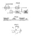
- Figure 5 is a block diagram of the channel estimating demodulator;
- Figure 6 is a diagram illustrating the transmitted data stream in schematic form; and
- Figure 7 is a signal constellation diagram.
- Referring to Figure 1, the device for reducing interference in an r.f. received signal is incorporated in a radio receiver 1 for receiving SSB transmissions, and comprises an
interference rejection circuit 2 and a channel estimating demodulator 3, which receives digital data from an analogue-to-digital converter 4 which converts the audio output of the receiver 1 into digital form. - Referring to Figures 2 to 4, the interference rejection circuit will now be described. A spectrum of a typical audio output is shown in Figure 3. The two peaks represent interference e.g. formed by an interfering binary FSK transmission. The received signal is sampled and the corresponding spectrum is produced by
spectrum analyser 5. The general shape of the spectrum of the received signal will of course be known and this enables theinterference identification circuit 6 to generate a notional template T having the same general shape of spectrum as the transmitted signal. At the same time, the frequency spectrum is divided into a number of equal sub-bands across the spectrum of the signal incircuit 6. The amplitude of the spectrum is assessed in each sub-band and the sub-bands e.g. six sub-bands, of lowest amplitude are averaged. The template is then superimposed on the frequency spectrum by relating its level to the level of the average of the six lowest sub-bands. - Having done this, the circuit then assesses for each band whether the amplitude of the actual frequency response lies above or below the template and, if the amplitude lies above, the programmable filter generates a notch for that sub-band. If the output lies below the template, no notch is generated. Thus, the interfering peaks will result in corresponding notches in the programmable filter 7 (Figure 4), and the output of the filter 7 will have the interference filtered from it. The filter can be updated as often as desired. The notches are of uniform depth.
- The description of the demodulator 3 which follows assumes four-phase modulation of the transmitted carrier wave so that each transmitted symbol represents two bits of the data input to the modulator at the transmitter.
- The channel estimating demodulator 3 receives the filtered signal and demodulates it in demodulator 8 with a complex tone at the subcarrier frequency i.e. signals 90° out of phase, to produce two streams of samples, one in-phase and the other quadrature. A typical sequence of samples is shown in Figure 6. The transmitter transmits 160 symbols of data followed by 40 reference (training) symbols in frames of 200 symbols. The same 40 reference symbols are stored in the demodulator in
training sequence generator 9. Each symbol can have one of four values i.e. 00, 01, 10, 11 which may be represented on the signal constellation diagram in Figure 7. - Frame timing is initially established by correlation with the known training sequence.
- It will be appreciated that the carrier frequency is in the HF band (3 - 30 MHz) and transmission will normally be by sky wave. The ionosphere is liable to produce multiple reflections of the transmitted signal, and the received signal will consequently suffer from multi-path distortion. The frequency response of this communication channel can be ascertained or, rather, its impulse response can be determined, and then possible combinations of signals can be passed through to ascertain which is the nearest to the received signal and hence the likeliest one to have been transmitted.
- In the presence of multipath and interference excision the output of the demodulator 8 would be a severely distorted version of the constellation. It is the function of the
channel estimating decoder 10 to recover the original transmitted data without the application of an inverse filtering operation. - The impulse response of the communication channel, which includes both the ionospheric path and the
excision filter 2, is estimated by comparing the distorted training sequence symbols appearing at the output of the demodulator 8 with the training sequence symbols ingenerator 9, which are identical to those in the transmitted signal. The impulse response estimate is made up, for example, of twelve complex values of 16 bits real and 16 bits imaginary. - The channel estimator update algorithm has two modes of operation. For operation in each mode it requires three inputs. These are: the received (distorted) data symbols; a model of the complex impulse response of the ionospheric path plus the excision filters (the channel estimate itself); and a digital reference signal. The last, during training, is the appropriate "n" successive symbols of the known, locally generated, training sequence and, during decision-directed operation, is an array of the "n" most recent decisions made by the detector (where n is the length of the channel estimate, measured in symbol periods).
- In its simplest form, the operation of the channel estimating demodulator is as follows. It is assumed that the
channel estimator 10 already contains a model of the impulse response of the transmission channel (including filter 2), and that it contains a series of the n most recent decisions made by thedetector 11. - It will be remembered that each new symbol received at the output of the
delay 12 could result from any one of four possible transmitted symbols, S1, S2, S3 or S4 (Figure 7). The series of n most recent decisions is thus expanded into four series of n symbols, the oldest symbol being discarded to hold the length at n, the last symbol being each of the four possible symbols. Each of the four series of n symbols thus obtained is convolved with the impulse response of the channel estimate, and four estimates of the symbol which was actually transmitted are obtained. For example, these could be represented by the points E1, E2, E3 and E4 in Figure 7, while the actual symbol newly arrived at the output of delay 7 could be R as shown in Figure 7. Each estimate is associated with a cost, which gives a measure of the distance on the signal constellation diagram between each estimate and the respective received symbol. - A decision is made in favour of the estimate with the lowest cost, in the case of Figure 7, estimate E1, and the decision thus assumes that symbol S1 is the most likely to have been transmitted.
- Because the ionosphere changes rapidly, the channel estimate may not be valid for symbols arriving subsequently. Consequently, the cost of the estimate decided upon is used to update the model of the complex channel impulse response (channel estimate).
- At the beginning of each received data frame, all the components of the channel estimate array are cleared to zero value. The new estimate is then constructed by successive once-per-symbol iterations of the channel estimator update process using the appropriate symbols of the known training sequence in place of the decision sequence (history). During this time the detection process is not required.
- After the end of the training period the updating process must be suspended for a period equal to the delay in the data detection process. When (decision-directed) update is resumed, the last "n" symbols of the known training sequence are used as the digital reference sequence input to the channel estimator. On successive symbols thereafter, the new data decisions are appended to this decision history, and its oldest components are discarded to hold its length at "n".
- To improve the accuracy of the decisions, instead of using a single series of n previous decisions, a larger number of series of previous symbols may be used. In this case some of the n symbols will not be the decisions but will be other symbols which could also (perhaps with lower probability) have produced the received symbol. Each of these series are expanded with each of the four possible symbols S1, S2, S3 and S4 and convolved with the model of the impulse response of the channel and filter 7. A larger number of estimates and associated costs will be produced and a decision made in favour of one of them.
- Further accuracy may be gained by using several models of the impulse response of the channel and filter 7, each expanded series of n symbols being convolved with each model of the impulse response, producing a larger number of estimates and costs. In this case, the detector becomes similar to a "Viterbi" decoder i.e. a maximum likelihood or near maximum likelihood detector (except that a reduced number of channel estimates are used). Examples of this type of detection process are described in "Adaptive Detectors for Digital Modems" by A. P. Clark, published in 1989 by the Pentech Press, London.
- The advantage of using a channel estimating demodulator to compensate for the response of the channel is that it does not counteract the operation of the interference rejection filter. If an equaliser was used to compensate for the response of the channel, this would also attempt to equalise the notches in the interference rejection filter, and the operation of the interference rejection filter would be nullified.
- Variations may be made without departing from the scope of the invention. Thus, instead of using the interference rejection filter described, an adaptive filter may be used. Such a filter monitors its output to minimise mean square output power. The effect of this would be to attenuate any peaks in the spectrum of the received signal. In this case, the spectrum of the received signal is not monitored as such, and this alternative is only of use where the spectrum of the transmitted signal is known to be basically flat, so that the peaks which the adaptive filter attempts to attenuate are from interfering signals. Also, the invention is applicable as well to the VHF region of the spectrum and other regions, and is also applicable to data rates other than those referred to. While the components of the device have been described in terms of hardware, the invention is also applicable to the case where they are implemented by software.
Claims (10)
- A device for reducing in-band interference in an r.f. received signal representing digital data, comprising means for filtering interfering signals from the received signal, and means for deciding the most likely digital data to have been transmitted by comparing the filtered received signal with locally generated signals processed in dependence on the estimated response of the communication channel.
- A device as claimed in claim 1, in which the filter means is arranged to produce attenuation at frequencies at which the r.f. received signal spectrum has peaks which are not present in the known spectrum of the transmitted signal.
- A device as claimed in claim 2, in which the filter means is arranged to produce the attenuation in response to a comparison of the spectrum of the received signal with the known spectrum of the transmitted signal.
- A device as claimed in claim 3, in which the filter means is arranged to produce notches of uniform depth at the frequencies at which it attenuates.
- A device as claimed in any one of claims 1 to 4, in which the received signal represents a digital data stream interspersed with reference samples.
- A device as claimed in claim 5, in which in use the estimated response of the channel is updated using the received reference samples and each possible state, locally generated, for each reference sample in turn.
- A device as claimed in claim 6, in which in use, for each newly received data sample, a plurality of series of decisions each together with one possible sample state for the newly received sample, are convolved with the impulse response of the estimate of the response of the channel and filter means, in order to obtain the most likely sample state to have been transmitted corresponding to the newly received data sample.
- A device as claimed in any one of claims 1 to 7, in which the r.f. carrier frequency is in the range of 3 to 30 MHZ.
- A device substantially as herein described with reference to the accompanying drawings.
- A receiver incorporating a device as claimed in any one of claims 1 to 9.
Applications Claiming Priority (2)
| Application Number | Priority Date | Filing Date | Title |
|---|---|---|---|
| GB9008613 | 1990-04-17 | ||
| GB909008613A GB9008613D0 (en) | 1990-04-17 | 1990-04-17 | Reducing interference in r.f.signals |
Publications (3)
| Publication Number | Publication Date |
|---|---|
| EP0453213A2 true EP0453213A2 (en) | 1991-10-23 |
| EP0453213A3 EP0453213A3 (en) | 1994-03-09 |
| EP0453213B1 EP0453213B1 (en) | 2000-06-28 |
Family
ID=10674539
Family Applications (1)
| Application Number | Title | Priority Date | Filing Date |
|---|---|---|---|
| EP91303308A Expired - Lifetime EP0453213B1 (en) | 1990-04-17 | 1991-04-15 | Reducing interference in R.F. signals |
Country Status (7)
| Country | Link |
|---|---|
| US (1) | US5278870A (en) |
| EP (1) | EP0453213B1 (en) |
| JP (1) | JPH08107367A (en) |
| AU (1) | AU643265B2 (en) |
| DE (1) | DE69132265T2 (en) |
| GB (2) | GB9008613D0 (en) |
| NO (1) | NO911457L (en) |
Cited By (17)
| Publication number | Priority date | Publication date | Assignee | Title |
|---|---|---|---|---|
| EP0542520A2 (en) * | 1991-11-14 | 1993-05-19 | Nokia Mobile Phones Ltd. | Adjustable filter means |
| EP0560599A1 (en) * | 1992-03-11 | 1993-09-15 | Matsushita Electric Industrial Co., Ltd. | Noise suppression apparatus |
| EP0629054A2 (en) * | 1993-06-08 | 1994-12-14 | Matsushita Electric Industrial Co., Ltd. | Noise suppressing apparatus capable of preventing deterioration in high frequency signal characteristic after noise suppression and in balanced signal transmitting system |
| US5430894A (en) * | 1992-03-11 | 1995-07-04 | Matsushita Electric Industrial Co., Ltd. | Radio receiver noise suppression system |
| WO1996037981A1 (en) * | 1995-05-23 | 1996-11-28 | Libit Signal Processing, Inc. | Digital communications on overlapping channels |
| WO1997014227A1 (en) * | 1995-10-10 | 1997-04-17 | Northern Telecom Limited | Co-channel interference reduction |
| WO1998024189A1 (en) * | 1996-11-29 | 1998-06-04 | Northern Telecom Limited | Selective filtering for co-channel interference reduction |
| EP0862300A2 (en) * | 1997-02-28 | 1998-09-02 | Orckit Communications Ltd. | Apparatus and method for transmission of high speed data over communication channels |
| WO1999039444A1 (en) * | 1998-01-30 | 1999-08-05 | Motorola, Inc. | METHOD AND APPARATUS FOR PERFORMING TARGETED INTERFERENCE SUPPRESSION _____________________________________________________________è |
| US6052420A (en) * | 1997-05-15 | 2000-04-18 | Northern Telecom Limited | Adaptive multiple sub-band common-mode RFI suppression |
| EP0773643A3 (en) * | 1995-11-09 | 2000-11-08 | Nortel Networks Limited | An interference reduction scheme and method |
| EP0772309A3 (en) * | 1995-11-04 | 2000-11-08 | Nortel Networks Limited | Interference reduction in telecommunication systems |
| WO2001022571A1 (en) * | 1999-09-17 | 2001-03-29 | Telefonaktiebolaget Lm Ericsson (Publ) | Apparatus and method for substantially eliminating a near-channel interfering amplitude modulated signal |
| WO2002080381A2 (en) * | 2001-03-28 | 2002-10-10 | Motorola, Inc., A Corporation Of The State Of Delaware | Radio receiver having a dynamic bandwidth filter and method therefor |
| EP1481519A1 (en) * | 2002-03-04 | 2004-12-01 | Glowlink Communications Technology, Inc. | Detecting and measuring interference contained within a digital carrier |
| EP1744455A2 (en) * | 2005-07-12 | 2007-01-17 | Tredess 2010, S.L. | Signal processing system for spectrum shaping |
| CN101771638A (en) * | 2010-02-23 | 2010-07-07 | 华为终端有限公司 | Channel estimation method and device |
Families Citing this family (13)
| Publication number | Priority date | Publication date | Assignee | Title |
|---|---|---|---|---|
| CA2125468C (en) * | 1993-06-28 | 1998-04-21 | Danny Thomas Pinckley | Method of selectively reducing spectral components in a wideband radio frequency signal |
| US5465256A (en) * | 1993-12-23 | 1995-11-07 | Krone Ag | Telephone cross connect status signal pre-processor |
| GB2287620B (en) * | 1994-03-10 | 1998-12-16 | Roke Manor Research | A digital cellular mobile radio receiver |
| US6130894A (en) | 1998-03-09 | 2000-10-10 | Broadcom Homenetworking, Inc. | Off-line broadband network interface |
| SE517039C2 (en) * | 2000-05-31 | 2002-04-02 | Bjoern Ottersten | Device and method for channel interference suppression |
| US7054386B1 (en) * | 2000-06-09 | 2006-05-30 | Motorola, Inc. | Method and apparatus for assigning bit metrics for soft decision decoding |
| US6901244B1 (en) * | 2000-10-23 | 2005-05-31 | Oren Semiconductor Ltd. | Training signal in a single carrier transmission |
| US6826242B2 (en) * | 2001-01-16 | 2004-11-30 | Broadcom Corporation | Method for whitening colored noise in a communication system |
| US6798854B2 (en) * | 2001-01-16 | 2004-09-28 | Broadcom Corporation | System and method for canceling interference in a communication system |
| GB2376158B (en) * | 2001-05-30 | 2004-07-28 | Salah A Al-Chalabi | Opto-electronic receiver which compensates for dispersion |
| SE521246C2 (en) * | 2001-06-12 | 2003-10-14 | Ericsson Telefon Ab L M | blind Detection |
| US7561864B2 (en) * | 2006-12-03 | 2009-07-14 | General Dynamics C4 Systems, Inc. | RF receiver with NLMS channel estimator and method therefor |
| US10148345B2 (en) | 2013-07-26 | 2018-12-04 | Massachusetts Institute Of Technology | Accurate timing distribution by high-frequency radio |
Citations (4)
| Publication number | Priority date | Publication date | Assignee | Title |
|---|---|---|---|---|
| DE3246525A1 (en) * | 1982-12-16 | 1984-06-20 | Licentia Patent-Verwaltungs-Gmbh, 6000 Frankfurt | Device for equalisation of linear time-invariant or slowly time-variant data transmission channels |
| EP0184618A1 (en) * | 1984-11-30 | 1986-06-18 | ANT Nachrichtentechnik GmbH | Resonant equalizer control method |
| WO1988002954A1 (en) * | 1986-10-08 | 1988-04-21 | Robert Bosch Gmbh | Circuitry for converting measurement signals disturbed by a disturbance function into undisturbed signals |
| WO1988009591A1 (en) * | 1987-05-19 | 1988-12-01 | Stiftelsen For Industriell Og Teknisk Forskning Ve | Method of demodulation in digital communication systems with multipath propagation |
Family Cites Families (7)
| Publication number | Priority date | Publication date | Assignee | Title |
|---|---|---|---|---|
| US4713817A (en) * | 1985-04-25 | 1987-12-15 | Codex Corporation | Multidimensional, convolutionally coded communication systems |
| US4713829A (en) * | 1985-06-19 | 1987-12-15 | Codex Corporation | Coded modulation system with a simplified decoder capable of reducing the effects of channel distortion |
| US4644562A (en) * | 1985-08-28 | 1987-02-17 | At&T Company | Combined cross polarization interference cancellation and intersymbol interference equalization for terrestrial digital radio systems |
| GB2198015B (en) * | 1986-11-15 | 1990-09-12 | Plessey Co Plc | Decoding apparatus |
| US5127051A (en) * | 1988-06-13 | 1992-06-30 | Itt Corporation | Adaptive modem for varying communication channel |
| US5020078A (en) * | 1989-08-11 | 1991-05-28 | Bell Communications Research, Inc. | Baudrate timing recovery technique |
| SE464902B (en) * | 1989-10-24 | 1991-06-24 | Ericsson Telefon Ab L M | PROCEDURE TO ADAPT A VITERBIAL ALGORITHM TO A CHANNEL WITH VARIOUS TRANSFER PROPERTIES AND A DEVICE IMPLEMENTING PROCEDURE |
-
1990
- 1990-04-17 GB GB909008613A patent/GB9008613D0/en active Pending
-
1991
- 1991-04-12 US US07/684,395 patent/US5278870A/en not_active Expired - Fee Related
- 1991-04-15 EP EP91303308A patent/EP0453213B1/en not_active Expired - Lifetime
- 1991-04-15 DE DE69132265T patent/DE69132265T2/en not_active Expired - Fee Related
- 1991-04-15 NO NO91911457A patent/NO911457L/en unknown
- 1991-04-15 GB GB9108106A patent/GB2243271B/en not_active Expired - Fee Related
- 1991-04-16 AU AU75026/91A patent/AU643265B2/en not_active Ceased
- 1991-04-17 JP JP3177844A patent/JPH08107367A/en active Pending
Patent Citations (4)
| Publication number | Priority date | Publication date | Assignee | Title |
|---|---|---|---|---|
| DE3246525A1 (en) * | 1982-12-16 | 1984-06-20 | Licentia Patent-Verwaltungs-Gmbh, 6000 Frankfurt | Device for equalisation of linear time-invariant or slowly time-variant data transmission channels |
| EP0184618A1 (en) * | 1984-11-30 | 1986-06-18 | ANT Nachrichtentechnik GmbH | Resonant equalizer control method |
| WO1988002954A1 (en) * | 1986-10-08 | 1988-04-21 | Robert Bosch Gmbh | Circuitry for converting measurement signals disturbed by a disturbance function into undisturbed signals |
| WO1988009591A1 (en) * | 1987-05-19 | 1988-12-01 | Stiftelsen For Industriell Og Teknisk Forskning Ve | Method of demodulation in digital communication systems with multipath propagation |
Cited By (36)
| Publication number | Priority date | Publication date | Assignee | Title |
|---|---|---|---|---|
| EP0542520A3 (en) * | 1991-11-14 | 1994-01-05 | Nokia Mobile Phones Ltd | |
| US5396657A (en) * | 1991-11-14 | 1995-03-07 | Nokia Mobile Phones Ltd. | Selectable filter for reducing Gaussian noise, co-channel and adjacent channel interference in a radio-telephone receiver |
| EP0542520A2 (en) * | 1991-11-14 | 1993-05-19 | Nokia Mobile Phones Ltd. | Adjustable filter means |
| EP0560599A1 (en) * | 1992-03-11 | 1993-09-15 | Matsushita Electric Industrial Co., Ltd. | Noise suppression apparatus |
| US5428832A (en) * | 1992-03-11 | 1995-06-27 | Matsushita Electric Industrial Co., Ltd. | Noise suppression apparatus |
| US5430894A (en) * | 1992-03-11 | 1995-07-04 | Matsushita Electric Industrial Co., Ltd. | Radio receiver noise suppression system |
| US5982901A (en) * | 1993-06-08 | 1999-11-09 | Matsushita Electric Industrial Co., Ltd. | Noise suppressing apparatus capable of preventing deterioration in high frequency signal characteristic after noise suppression and in balanced signal transmitting system |
| EP0629054A2 (en) * | 1993-06-08 | 1994-12-14 | Matsushita Electric Industrial Co., Ltd. | Noise suppressing apparatus capable of preventing deterioration in high frequency signal characteristic after noise suppression and in balanced signal transmitting system |
| EP0629054A3 (en) * | 1993-06-08 | 1997-01-29 | Matsushita Electric Ind Co Ltd | Noise suppressing apparatus capable of preventing deterioration in high frequency signal characteristic after noise suppression and in balanced signal transmitting system. |
| WO1996037981A1 (en) * | 1995-05-23 | 1996-11-28 | Libit Signal Processing, Inc. | Digital communications on overlapping channels |
| US5710797A (en) * | 1995-05-23 | 1998-01-20 | Libit Signal Processing Inc. | Method and apparatus for digital communication in the presence of closely spaced adjacent channels |
| AU726221B2 (en) * | 1995-05-23 | 2000-11-02 | Libit Signal Processing, Inc. | Digital communications on overlapping channels |
| WO1997014227A1 (en) * | 1995-10-10 | 1997-04-17 | Northern Telecom Limited | Co-channel interference reduction |
| EP0772309A3 (en) * | 1995-11-04 | 2000-11-08 | Nortel Networks Limited | Interference reduction in telecommunication systems |
| EP0773643A3 (en) * | 1995-11-09 | 2000-11-08 | Nortel Networks Limited | An interference reduction scheme and method |
| CN1110906C (en) * | 1996-11-29 | 2003-06-04 | 北方电讯网络有限公司 | Selective filtering for co-channel interference reduction |
| WO1998024189A1 (en) * | 1996-11-29 | 1998-06-04 | Northern Telecom Limited | Selective filtering for co-channel interference reduction |
| US5848108A (en) * | 1996-11-29 | 1998-12-08 | Northern Telecom Limited | Selective filtering for co-channel interference reduction |
| EP0862300A2 (en) * | 1997-02-28 | 1998-09-02 | Orckit Communications Ltd. | Apparatus and method for transmission of high speed data over communication channels |
| EP0862300A3 (en) * | 1997-02-28 | 2001-04-11 | Orckit Communications Ltd. | Apparatus and method for transmission of high speed data over communication channels |
| US6285718B1 (en) | 1997-02-28 | 2001-09-04 | Orckit Communication Ltd. | Adaptive noise canceller |
| US6052420A (en) * | 1997-05-15 | 2000-04-18 | Northern Telecom Limited | Adaptive multiple sub-band common-mode RFI suppression |
| GB2350040B (en) * | 1998-01-30 | 2003-04-02 | Motorola Inc | Method and apparatus for performing targeted interference suppression |
| US6131013A (en) * | 1998-01-30 | 2000-10-10 | Motorola, Inc. | Method and apparatus for performing targeted interference suppression |
| WO1999039444A1 (en) * | 1998-01-30 | 1999-08-05 | Motorola, Inc. | METHOD AND APPARATUS FOR PERFORMING TARGETED INTERFERENCE SUPPRESSION _____________________________________________________________è |
| GB2350040A (en) * | 1998-01-30 | 2000-11-15 | Motorola Inc | Method and apparatus for performing targeted interference suppression |
| US6934346B2 (en) | 1999-09-17 | 2005-08-23 | Telefonaktiebolaget L M Ericsson (Publ) | Apparatus and method for substantially eliminating a near-channel interfering amplitude modulated signal |
| WO2001022571A1 (en) * | 1999-09-17 | 2001-03-29 | Telefonaktiebolaget Lm Ericsson (Publ) | Apparatus and method for substantially eliminating a near-channel interfering amplitude modulated signal |
| WO2002080381A3 (en) * | 2001-03-28 | 2003-02-27 | Motorola Inc | Radio receiver having a dynamic bandwidth filter and method therefor |
| WO2002080381A2 (en) * | 2001-03-28 | 2002-10-10 | Motorola, Inc., A Corporation Of The State Of Delaware | Radio receiver having a dynamic bandwidth filter and method therefor |
| US6658245B2 (en) | 2001-03-28 | 2003-12-02 | Motorola, Inc. | Radio receiver having a dynamic bandwidth filter and method therefor |
| EP1481519A1 (en) * | 2002-03-04 | 2004-12-01 | Glowlink Communications Technology, Inc. | Detecting and measuring interference contained within a digital carrier |
| EP1481519A4 (en) * | 2002-03-04 | 2009-06-24 | Glowlink Communications Technology Inc | Detecting and measuring interference contained within a digital carrier |
| US7639761B2 (en) | 2002-03-04 | 2009-12-29 | Glowlink Communications Technology, Inc. | Detecting and measuring interference contained within a digital carrier |
| EP1744455A2 (en) * | 2005-07-12 | 2007-01-17 | Tredess 2010, S.L. | Signal processing system for spectrum shaping |
| CN101771638A (en) * | 2010-02-23 | 2010-07-07 | 华为终端有限公司 | Channel estimation method and device |
Also Published As
| Publication number | Publication date |
|---|---|
| US5278870A (en) | 1994-01-11 |
| EP0453213B1 (en) | 2000-06-28 |
| NO911457D0 (en) | 1991-04-15 |
| GB9108106D0 (en) | 1991-06-05 |
| DE69132265D1 (en) | 2000-08-03 |
| AU7502691A (en) | 1991-10-24 |
| GB2243271A (en) | 1991-10-23 |
| AU643265B2 (en) | 1993-11-11 |
| NO911457L (en) | 1991-10-18 |
| GB2243271B (en) | 1994-07-06 |
| JPH08107367A (en) | 1996-04-23 |
| GB9008613D0 (en) | 1990-06-13 |
| DE69132265T2 (en) | 2000-10-26 |
| EP0453213A3 (en) | 1994-03-09 |
Similar Documents
| Publication | Publication Date | Title |
|---|---|---|
| EP0453213B1 (en) | Reducing interference in R.F. signals | |
| Tsatsanis et al. | Modelling and equalization of rapidly fading channels | |
| KR970007362B1 (en) | Equalizing device in receiver | |
| US6535554B1 (en) | PCS signal separation in a one dimensional channel | |
| US5822368A (en) | Developing a channel impulse response by using distortion | |
| US5748686A (en) | System and method producing improved frame synchronization in a digital communication system | |
| US8144758B2 (en) | Method and apparatus for single burst equalization of single carrier signals in broadband wireless access systems | |
| US5353307A (en) | Automatic simulcast alignment | |
| US5815529A (en) | Transmission system for digital audio broadcasting that incorporates a rotator in the transmitter | |
| US5802079A (en) | Transmission system for digital audio broadcasting | |
| US5751774A (en) | Transmission system for digital audio broadcasting | |
| CA2345534A1 (en) | Adaptive channel tracking using pilot sequences | |
| Clark et al. | Assessment of Kalman-filter channel estimators for an HF radio link | |
| US7302233B2 (en) | Multiuser detection for wireless communications systems in the presence of interference | |
| US7526022B2 (en) | Low complexity equalizer | |
| US8743910B2 (en) | Method and apparatus for selecting a channel filter for a communication system | |
| US7991047B2 (en) | Method for designing a digital reception filter and corresponding receiving device | |
| JPH05199143A (en) | Adaptive equalizing method for decreasing inter- ference between symbols, receiver for performing method thereof and application system thereof | |
| US7016650B2 (en) | Multi-path adaptive receiver apparatus and method for the reception of frequency shift keyed signals | |
| WO1993022853A1 (en) | Optimum estimation of data and parameters for communication systems | |
| Gu et al. | An effective lms equalizer for the gsm chipset |
Legal Events
| Date | Code | Title | Description |
|---|---|---|---|
| PUAI | Public reference made under article 153(3) epc to a published international application that has entered the european phase |
Free format text: ORIGINAL CODE: 0009012 |
|
| AK | Designated contracting states |
Kind code of ref document: A2 Designated state(s): DE FR IT NL SE |
|
| PUAL | Search report despatched |
Free format text: ORIGINAL CODE: 0009013 |
|
| AK | Designated contracting states |
Kind code of ref document: A3 Designated state(s): DE FR IT NL SE |
|
| RHK1 | Main classification (correction) |
Ipc: H04L 25/03 |
|
| 17P | Request for examination filed |
Effective date: 19940908 |
|
| 17Q | First examination report despatched |
Effective date: 19961217 |
|
| GRAG | Despatch of communication of intention to grant |
Free format text: ORIGINAL CODE: EPIDOS AGRA |
|
| GRAG | Despatch of communication of intention to grant |
Free format text: ORIGINAL CODE: EPIDOS AGRA |
|
| GRAH | Despatch of communication of intention to grant a patent |
Free format text: ORIGINAL CODE: EPIDOS IGRA |
|
| GRAH | Despatch of communication of intention to grant a patent |
Free format text: ORIGINAL CODE: EPIDOS IGRA |
|
| GRAH | Despatch of communication of intention to grant a patent |
Free format text: ORIGINAL CODE: EPIDOS IGRA |
|
| GRAA | (expected) grant |
Free format text: ORIGINAL CODE: 0009210 |
|
| RAP1 | Party data changed (applicant data changed or rights of an application transferred) |
Owner name: MARCONI MOBILE LIMITED |
|
| AK | Designated contracting states |
Kind code of ref document: B1 Designated state(s): DE FR IT NL SE |
|
| ITF | It: translation for a ep patent filed |
Owner name: JACOBACCI & PERANI S.P.A. |
|
| ET | Fr: translation filed | ||
| REF | Corresponds to: |
Ref document number: 69132265 Country of ref document: DE Date of ref document: 20000803 |
|
| PGFP | Annual fee paid to national office [announced via postgrant information from national office to epo] |
Ref country code: SE Payment date: 20010404 Year of fee payment: 11 |
|
| PGFP | Annual fee paid to national office [announced via postgrant information from national office to epo] |
Ref country code: FR Payment date: 20010409 Year of fee payment: 11 Ref country code: DE Payment date: 20010409 Year of fee payment: 11 |
|
| PLBE | No opposition filed within time limit |
Free format text: ORIGINAL CODE: 0009261 |
|
| STAA | Information on the status of an ep patent application or granted ep patent |
Free format text: STATUS: NO OPPOSITION FILED WITHIN TIME LIMIT |
|
| PGFP | Annual fee paid to national office [announced via postgrant information from national office to epo] |
Ref country code: NL Payment date: 20010430 Year of fee payment: 11 |
|
| 26N | No opposition filed | ||
| PG25 | Lapsed in a contracting state [announced via postgrant information from national office to epo] |
Ref country code: SE Free format text: LAPSE BECAUSE OF NON-PAYMENT OF DUE FEES Effective date: 20020416 |
|
| PG25 | Lapsed in a contracting state [announced via postgrant information from national office to epo] |
Ref country code: NL Free format text: LAPSE BECAUSE OF NON-PAYMENT OF DUE FEES Effective date: 20021101 Ref country code: DE Free format text: LAPSE BECAUSE OF NON-PAYMENT OF DUE FEES Effective date: 20021101 |
|
| EUG | Se: european patent has lapsed |
Ref document number: 91303308.0 |
|
| PG25 | Lapsed in a contracting state [announced via postgrant information from national office to epo] |
Ref country code: FR Free format text: LAPSE BECAUSE OF NON-PAYMENT OF DUE FEES Effective date: 20021231 |
|
| NLV4 | Nl: lapsed or anulled due to non-payment of the annual fee |
Effective date: 20021101 |
|
| REG | Reference to a national code |
Ref country code: FR Ref legal event code: ST |
|
| PG25 | Lapsed in a contracting state [announced via postgrant information from national office to epo] |
Ref country code: IT Free format text: LAPSE BECAUSE OF NON-PAYMENT OF DUE FEES;WARNING: LAPSES OF ITALIAN PATENTS WITH EFFECTIVE DATE BEFORE 2007 MAY HAVE OCCURRED AT ANY TIME BEFORE 2007. THE CORRECT EFFECTIVE DATE MAY BE DIFFERENT FROM THE ONE RECORDED. Effective date: 20050415 |