EP0453608A1 - Method for automatic redialling of selective dial information recorded in a memory - Google Patents
Method for automatic redialling of selective dial information recorded in a memory Download PDFInfo
- Publication number
- EP0453608A1 EP0453608A1 EP90108056A EP90108056A EP0453608A1 EP 0453608 A1 EP0453608 A1 EP 0453608A1 EP 90108056 A EP90108056 A EP 90108056A EP 90108056 A EP90108056 A EP 90108056A EP 0453608 A1 EP0453608 A1 EP 0453608A1
- Authority
- EP
- European Patent Office
- Prior art keywords
- information
- dialing
- dialing information
- communication terminal
- input means
- Prior art date
- Legal status (The legal status is an assumption and is not a legal conclusion. Google has not performed a legal analysis and makes no representation as to the accuracy of the status listed.)
- Granted
Links
Images


Classifications
-
- H—ELECTRICITY
- H04—ELECTRIC COMMUNICATION TECHNIQUE
- H04M—TELEPHONIC COMMUNICATION
- H04M1/00—Substation equipment, e.g. for use by subscribers
- H04M1/56—Arrangements for indicating or recording the called number at the calling subscriber's set
-
- H—ELECTRICITY
- H04—ELECTRIC COMMUNICATION TECHNIQUE
- H04M—TELEPHONIC COMMUNICATION
- H04M1/00—Substation equipment, e.g. for use by subscribers
- H04M1/26—Devices for calling a subscriber
- H04M1/27—Devices whereby a plurality of signals may be stored simultaneously
- H04M1/274—Devices whereby a plurality of signals may be stored simultaneously with provision for storing more than one subscriber number at a time, e.g. using toothed disc
- H04M1/2745—Devices whereby a plurality of signals may be stored simultaneously with provision for storing more than one subscriber number at a time, e.g. using toothed disc using static electronic memories, e.g. chips
- H04M1/27467—Methods of retrieving data
- H04M1/2747—Scrolling on a display
Definitions
- Communication terminals in particular telephony devices, have been equipped with redial functions for some time.
- the dialing information formed by dialing keys is stored automatically or by additional key input and the dialing information formed by speed dialing, name or direct call keys, if provided, predominantly by key input for a later redial in a redial memory. If there is no connection to the communication terminal determined by the dialing information - busy or unoccupied - the dialing information stored in the redial memory can be transmitted to the assigned communication system at any time by pressing a redial button in the sense of a renewed attempt to establish a connection.
- this redialing method only the last dialing information formed in the case of automatic storage and only one dialing information in each case for the establishment of a connection in the sense of a redialing when stored by key input.
- the object on which the invention is based is to design further dialing information already formed in the respective communication terminals in a redial process.
- the object is achieved on the basis of a communication terminal connected to a communication system in accordance with the preamble of claim 1 by its characterizing features.
- the essential aspect of the invention is to be seen in the fact that a plurality of dialing information items which have been input in the event of unsuccessful or successful connection attempts are recorded in a dialing information storage device and by means of a search input means - e.g. B. search button - the recorded dialing information can be controlled one after the other in the sense of a search for a specific recorded dialing information, each controlled recorded dialing information being displayed optically and / or acoustically in the communication terminal.
- a search input means arranged on the communication terminal - e.g. B. Redial button - a connection is established to the dialing information currently displayed optically or acoustically on the communication terminal.
- the dialing information arriving at the communication terminal can also be stored and marked in the dialing information storage device.
- the prerequisite for this is - this is the case in digital communication networks, in particular in the integrated data and telephone network (ISDN) - that the dialing information of the calling communication terminal is transmitted as part of a connection setup.
- ISDN integrated data and telephone network
- the dialing information is stored cyclically in a dialing information storage device limited with regard to the number of the partial storage areas, in the partial storage area order - see claim 3.
- the partial storage areas of the dialing information storage device are activated cyclically in the partial storage area order using the search input means - See claim 4.
- the number of partial memory areas is to be matched or limited on the one hand to the highest possible number of storable selection information and on the other hand to the shortest possible search times.
- the number of partial memory areas should, for. B. be dimensioned such that the search time using the input means does not significantly exceed the input time for an item of information to be entered.
- a marking symbol can be controlled from displayed election information to election information - see claim 5.
- the number of displayable election information is limited here by the display capacity of the display device.
- the election information is z. B. transmitted in groups from the partial storage areas to the display device and displayed there. If the marker symbol is driven to the upper or lower display area using the search button, the following selection information is, for example, in turn transmitted in groups to the display device and displayed there.
- the search input means e.g. B. search button, the marker icon is controlled to the desired election information. After pressing the redial key, the marked dialing information is transmitted to the communication system in the sense of establishing a connection.
- a display device AZE is provided for the display of digits, text and the dialing information.
- This display device AZE is implemented, for example, by an LCD display. It is also used to enter signaling and dialing information a keypad TF is provided.
- This keypad TF contains the numerical keys (not shown in detail) for entering dialing information and further keys for entering additional functions.
- One of these keys equipped with an additional function is a redial key WWT and a search key ST.
- the search process is initiated in a dialing information storage device. During this search, the recorded voting information is stored for a predetermined period of time, e.g. B.
- connection setup with the displayed dialing information is initiated after pressing the redial key WWT.
- the dialing information is led via a connection line ASL to a communication system KA and evaluated there for the further establishment of the connection.
- the central device for controlling the subscriber operating procedures, for controlling all acoustic signals to be transmitted in the communication terminal KE and for controlling the signaling with the communication system KA is implemented by a microprocessor system ⁇ P.
- this microprocessor system ⁇ P can be formed by a Siemens microprocessor SAB 80C31.
- the microprocessor system ⁇ P is connected to a program memory PS and a data memory DS via a local bus LB formed by control, address and data lines.
- the program memory PS implemented in ROM memory technology is designed, for example, for a program comprising a maximum of 64 KB.
- the 64 KByte data memory for example, can also contain half a ROM memory technology - for fixed data, parameter data and tables - and half a RAM memory technology - for example for storing user-specific data.
- RAM there is also the election information memory or the election information storage device Contain WIS, which has several partial storage areas TS.
- the microprocessor system ⁇ P also has a serial bus interface. This serial bus interface is connected to a control panel microprocessor system B ⁇ P via the serial bus SB.
- the auxiliary devices BSE connected to the communication terminal KE are also operated via this serial bus SB.
- the coded information generated by the control elements or keys of the keypad TF is recognized, serially transmitted to the microprocessor system ⁇ P via the serial bus SB and there for signaling information and operator guidance information - for example for light-emitting diodes, tones and displays in a display device - processed.
- a display device AZE is also connected to the local bus LB.
- the display device AZE is implemented, for example, by an LC display (two lines of 24 characters each). This LC display is used to display digits and plain text as well as dialing information.
- the communication terminal KE is connected to a subscriber line ASL via a connection device AE.
- the communication terminal KE communicates with a communication system KA via this subscriber line ASL.
- the 64 KByte / s messages and the 8 KByte / s signaling information are transmitted bidirectionally via the subscriber line ASL.
- the signaling information transmitted in the signaling channel is structured in accordance with the OSI reference model.
- the lower three protocol layers of the seven abstracted protocol layers of the OSI reference model are implemented.
- the protocol layers used for the communication terminals - communication system signaling - are defined as physical layer (layer 1), as data link layer (layer 2) and as a network layer (layer 3).
- the physical layer also referred to as the physical level, does this Transmission of the information in the message and signaling channels simultaneously in both directions. This includes activating, deactivating and operating the communication terminal KE.
- the data link layer takes over the secure transmission of the signaling information between the communication system KA and the communication terminal KE for the subsequent network layer.
- the network layer serves to set up, monitor and clear the communication connections as well as to control and monitor the performance features supported by the communication system KA.
- the functions of the physical layer (layer 1) and the control of the microprocessor system ⁇ P are essentially implemented in the connection device AE.
- the signaling information separated in the connection device AE from information transmitted via the connection line ASL is processed in accordance with the local bus and transmitted to the microprocessor system ⁇ P via the local bus LB. In the microprocessor system, this signaling information is further processed in accordance with the functions assigned to the data link layer and network layer and the corresponding reactions - e.g. B. control of output units - initiated.
- the message information separated in the connection device AE reaches an analog / digital conversion device A / D. In this, analog voice signals are formed from the digitized message or voice signals output by the connection device AE. The analog voice signals arriving at a further input of the analog / digital conversion device A / D are converted into digital voice signals.
- the analog voice signals reach a third input E3 of an acoustic device AKE via a corresponding connection.
- the acoustic device AKE is composed of an acoustic coupler AK and a control device ASE.
- the acoustic coupler AK transmits the analog signals arriving from the analog / digital conversion device A / D either only to a first output A1 or to the first and to a second output A1, A2.
- Output is A1 connected to the handset of the communication terminal KE via a preamplifier VV.
- the analog voice signals are routed via the preamplifier VV to an earpiece arranged in the handset HA.
- the voice signals emitted by a microphone arranged in the handset HA reach a first input E1 of the acoustic coupler AK via the preamplifier VV.
- the analog voice signals are conveyed through the acoustic coupler AK to a third output A3 connected to the analog / digital conversion device A / D.
- These analog voice signals are converted into digital signals in the analog / digital conversion device A / D and inserted into the message stream transmitted to the connection line ASL in the connection device AE.
- the analog voice signals arriving at the third input E3 are simultaneously led to a second output A2 of the acoustic coupler AK. From there, the analog voice signals pass through an amplifier V to a loudspeaker LS arranged in the communication terminal KE.
- the control device ASE arranged in the acoustic device AKE is connected both to the acoustic coupler AK and to the local bus LB. In this control device ASE, the control commands transmitted by the microprocessor system ⁇ P via the local bus LB are converted into information by means of which the connection paths in the acoustic coupler AK are set.
- the acoustic coupler AK is implemented, for example, by analog crosspoints implemented in CMOS technology.
- the control device ASE controls a ring tone generator RT which, depending on the control, generates different ring tones with corresponding ringing rhythms. These ringing tones are transmitted to the handset HA and / or the loudspeaker LS via the acoustic coupler AK under the control of the control device ASE.
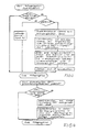
- 3 and 4 show the self-explanatory program flow diagrams for searching for dialing information in the dialing information storage device WIS and initiating a connection setup with the dialing information sought by actuation the redial key WWT.
- the program that realizes these program sequences is stored in the program memory PS of the communication terminal KE.
- the dialing information output by the dialing buttons is recognized in the control panel microprocessor system B ⁇ P, the corresponding dialing information is coded and transmitted via the microprocessor ⁇ P to the respective partial memory areas TS of the dialing information storage device WIS.
- the election information is, for example, successively, for. B. cyclically in memory addresses in descending order, stored in the election information storage device WIS. Analogously to this, as shown in FIG. 3, the election information from the election information storage device WIS can be controlled, read and displayed in the display device AZE cyclically, in ascending order in memory addresses using the search key ST.
- the selection information can also be transmitted in groups to the display device AZE, displayed there and selected using the search key ST or a marking symbol.
- the display duration of the selected information is implemented by a counting loop. If, for example, the query cycle is initialized every 25 ms for all keys, the display duration is 20 times 25 ms, i.e. 500 ms.
- the display duration can be determined by varying the maximum counter value. This maximum counter value can be determined individually by a corresponding entry or by stored information, for example. B. in the database.
Abstract
Description
Kommunikationsendgeräte, insbesondere Fernsprechendgeräte, sind seit geraumer Zeit mit Wahlwiederholungsfunktionen ausgestattet. Hierbei werden während des Verbindungsaufbaus die durch Wähltasten gebildeten Wahlinformationen automatisch oder durch zusätzliche Tasteneingabe und die durch Kurzwahl-, Namen- oder Direktruftasten gebildeten Wahlinformationen, wenn vorgesehen, überwiegend durch Tasteneingabe für eine spätere Wahlwiederholung in einem Wahlwiederholungsspeicher hinterlegt. Kommt keine Verbindung mit dem durch die Wahlinformationen bestimmten Kommunikationsendgerät zustande - belegt oder unbesetzt -, so kann die im Wahlwiederholungsspeicher gespeicherte Wahlinformation durch Betätigen einer Wahlwiederholungstaste zu einem beliebigen Zeitpunkt im Sinne eines erneuten Verbindungsaufbauversuches zur zugeordneten Kommunikationsanlage übermittelt werden. Bei diesem Wahlwiederholungsverfahren kann bei automatischer Speicherung nur jeweils die zuletzt gebildete Wahlinformation und bei Speicherung durch Tasteneingabe nur jeweils eine Wahlinformation für einen Verbindungsaufbau im Sinne einer Wahlwiederholung herangezogen werden.Communication terminals, in particular telephony devices, have been equipped with redial functions for some time. Here, during the establishment of the connection, the dialing information formed by dialing keys is stored automatically or by additional key input and the dialing information formed by speed dialing, name or direct call keys, if provided, predominantly by key input for a later redial in a redial memory. If there is no connection to the communication terminal determined by the dialing information - busy or unoccupied - the dialing information stored in the redial memory can be transmitted to the assigned communication system at any time by pressing a redial button in the sense of a renewed attempt to establish a connection. With this redialing method, only the last dialing information formed in the case of automatic storage and only one dialing information in each case for the establishment of a connection in the sense of a redialing when stored by key input.
Die der Erfindung zugrundeliegende Aufgabe besteht darin, weitere, bereits in den jeweiligen Kommunikationsendgeräten gebildete Wahlinformationen in ein Wahlwiederholungsverfahren auszugestalten. Die Aufgabe wird ausgehend von einem an eine Kommunikationsanlage angeschlossenen Kommunikationsendgerät gemäß Oberbegriff des Anspruches 1 durch dessen kennzeichnende Merkmale gelöst.The object on which the invention is based is to design further dialing information already formed in the respective communication terminals in a redial process. The object is achieved on the basis of a communication terminal connected to a communication system in accordance with the preamble of claim 1 by its characterizing features.
Der wesentliche Aspekt der Erfindung ist darin zu sehen, daß in einer Wahlinformations-Speichereinrichtung mehrere, bei erfolglosen oder erfolgreichen Verbindungsaufbauversuchen eingegebene Wahlinformationen aufgezeichnet werden und mit Hilfe eines Sucheingabemittels - z. B. Suchtaste - die aufgezeichneten Wahlinformationen im Sinne eines Suchens nach einer bestimmten aufgezeichneten Wahlinformation nacheinander ansteuerbar sind, wobei jede angesteuerte aufgezeichnete Wahlinformation im Kommunikationsendgerät optisch und/oder akustisch angezeigt wird. Durch Betätigen der am Kommunikationsendgerät angeordneten Wahlwiederholungseingabemittel - z. B. Wahlwiederholungstaste - wird ein Verbindungsaufbau der aktuell optisch oder akustisch am Kommunikationsendgerät angezeigten Wahlinformation eingeleitet.The essential aspect of the invention is to be seen in the fact that a plurality of dialing information items which have been input in the event of unsuccessful or successful connection attempts are recorded in a dialing information storage device and by means of a search input means - e.g. B. search button - the recorded dialing information can be controlled one after the other in the sense of a search for a specific recorded dialing information, each controlled recorded dialing information being displayed optically and / or acoustically in the communication terminal. By actuating the redial input means arranged on the communication terminal - e.g. B. Redial button - a connection is established to the dialing information currently displayed optically or acoustically on the communication terminal.
Gemäß einer vorteilhaften Weiterbildung der Erfindung können zusätzlich die am Kommunikationsendgerät ankommenden Wahlinformationen in der Wahlinformations-Speichereinrichtung gespeichert und markiert werden. Voraussetzung hierfür ist - dies ist in den digitalen Kommunikationsnetzen, insbesondere im integrierten Daten- und Fernsprechnetz (ISDN) der Fall - daß im Rahmen eines Verbindungsaufbaus die Wahlinformationen des rufenden Kommunikationsendgerätes übermittelt werden. Eine Markierung erleichtert während des Suchens die Unterscheidung zwischen intern und extern gebildeten Wahlinformationen.According to an advantageous development of the invention, the dialing information arriving at the communication terminal can also be stored and marked in the dialing information storage device. The prerequisite for this is - this is the case in digital communication networks, in particular in the integrated data and telephone network (ISDN) - that the dialing information of the calling communication terminal is transmitted as part of a connection setup. A marker makes it easier to distinguish between internally and externally generated election information while searching.
Gemäß einer weiteren Ausgestaltung der Erfindung werden die Wahlinformationen in einer hinsichtlich der Anzahl der Teilspeicherbereiche begrenzten Wahlinformations-Speichereinrichtung zyklisch, in Teilspeicherbereichs-Reihenfolge gespeichert - siehe Anspruch 3. Die Teilspeicherbereiche der Wahlinformations-Speichereinrichtung werden hierbei mit Hilfe des Sucheingabemittels in Teilspeicherbereichs-Reihenfolge zyklisch angesteuert - siehe Anspruch 4. Die Anzahl der Teilspeicherbereiche ist einerseits auf eine möglichst hohe Anzahl von speicherbaren Wahlinformationen und andererseits auf möglichst kurze Suchzeiten abzustimmen bzw. zu begrenzen. Die Anzahl der Teilspeicherbereiche sollte z. B. so bemessen sein, daß die Suchzeit mit Hilfe des Eingabemittels die Eingabezeit für eine einzugebende Wahlinformation nicht wesentlich übersteigt.According to a further embodiment of the invention, the dialing information is stored cyclically in a dialing information storage device limited with regard to the number of the partial storage areas, in the partial storage area order - see claim 3. The partial storage areas of the dialing information storage device are activated cyclically in the partial storage area order using the search input means - See claim 4. The number of partial memory areas is to be matched or limited on the one hand to the highest possible number of storable selection information and on the other hand to the shortest possible search times. The number of partial memory areas should, for. B. be dimensioned such that the search time using the input means does not significantly exceed the input time for an item of information to be entered.
Nach einer weiteren vorteilhaften Ausgestaltung der Erfindung werden mehrere Wahlinformationen mit Hilfe der Anzeigeeinrichtung simultan angezeigt und ist mit Hilfe des Sucheingabemittels ein Markierungssymbol von angezeigter Wahlinformation zu Wahlinformation steuerbar - siehe Anspruch 5. Die Anzahl der anzeigbaren Wahlinformationen ist hierbei durch die Anzeigekapazität der Anzeigeeinrichtung begrenzt. Die Wahlinformationen werden hierbei z. B. gruppenweise von den Teilspeicherbereichen zur Anzeigeeinrichtung übermittelt und dort angezeigt. Wird das Markierungssymbol mit Hilfe der Suchtaste an den oberen oder den unteren Anzeigebereich gesteuert, so werden die folgenden Wahlinformationen beispielsweise wiederum gruppenweise an die Anzeigeeinrichtung übermittelt und dort angezeigt. Mit Hilfe des Sucheingabemittels, z. B. Suchtaste, wird das Markierungssymbol an die gewünschte Wahlinformation gesteuert. Nach Betätigen der Wahlwiederholungstaste wird die markierte Wahlinformation im Sinne eines Verbindungsaufbaus an die Kommunikationsanlage übermittelt.According to a further advantageous embodiment of the invention, a plurality of selection information items are displayed using the display device displayed simultaneously and with the help of the search input means a marking symbol can be controlled from displayed election information to election information - see claim 5. The number of displayable election information is limited here by the display capacity of the display device. The election information is z. B. transmitted in groups from the partial storage areas to the display device and displayed there. If the marker symbol is driven to the upper or lower display area using the search button, the following selection information is, for example, in turn transmitted in groups to the display device and displayed there. With the help of the search input means, e.g. B. search button, the marker icon is controlled to the desired election information. After pressing the redial key, the marked dialing information is transmitted to the communication system in the sense of establishing a connection.
Im folgenden wird ein Ausführungsbeispiel der Erfindung anhand von Zeichnungen und eines Ablaufdiagrammes erläutert. Dabei zeigen
- FIG 1
- die Bedieneroberfläche eines Kommunikationsendgerätes,
- FIG 2
- in einem Blockschaltbild die wesentlichen Schaltungskomponenten eines Kommunikationsendgerätes,
- FIG 3
- ein Ablaufdiagramm zum Suchen von Wahlinformationen in einer Wahlinformations-Speichereinrichtung und
- FIG 4
- ein Ablaufdiagramm zur Wahlwiederholung mit der gesuchten Wahlinformation.
- FIG. 1
- the user interface of a communication terminal,
- FIG 2
- the essential circuit components of a communication terminal in a block diagram,
- FIG 3
- a flowchart for searching election information in an election information storage device and
- FIG 4
- a flowchart for redial with the dialing information sought.
FIG 1 zeigt die Draufsicht auf ein Kommunikationsendgerät KE mit einer aufgelegten Hör/Sprecheinrichtung HSE. Für die Anzeige von Ziffern, Text und den Wahlinformationen ist eine Anzeigeeinrichtung AZE vorgesehen. Diese Anzeigeeinrichtung AZE ist beispielsweise durch ein LCD-Display realisiert. Des weiteren ist für die Eingabe von Signalisierungs- und Wahlinformationen ein Tastenfeld TF vorgesehen. Dieses Tastenfeld TF enthält die nicht im einzelnen dargestellten numerischen Tasten für die Eingabe von Wahlinformationen und weitere Tasten für die Eingabe von Zusatzfunktionen. Eine dieser mit einer Zusatzfunktion ausgestatteten Taste ist eine Wahlwiederholungstaste WWT und eine Suchtaste ST. Durch Betätigen der Suchtaste ST wird der Suchvorgang in einer Wahlinformations-Speichereinrichtung eingeleitet. Während dieses Suchvorgangs werden die aufgezeichneten Wahlinformationen für eine vorgegebene Zeitspanne, z. B. 0,5 s, an der Anzeigeeinrichtung AZE angezeigt. Erscheint die gewünschte Wahlinformation in der Anzeigeeinrichtung AZE, so wird nach Betätigen der Wahlwiederholungstaste WWT ein Verbindungsaufbau mit der angezeigten Wahlinformation eingeleitet. Die Wahlinformationen werden über eine Anschlußleitung ASL zu einer Kommunikationsanlage KA geführt und dort für den weiteren Verbindungsaufbau ausgewertet.1 shows the top view of a communication terminal KE with an attached hearing / speaking device HSE. A display device AZE is provided for the display of digits, text and the dialing information. This display device AZE is implemented, for example, by an LCD display. It is also used to enter signaling and dialing information a keypad TF is provided. This keypad TF contains the numerical keys (not shown in detail) for entering dialing information and further keys for entering additional functions. One of these keys equipped with an additional function is a redial key WWT and a search key ST. By pressing the search key ST, the search process is initiated in a dialing information storage device. During this search, the recorded voting information is stored for a predetermined period of time, e.g. B. 0.5 s, displayed on the display device AZE. If the desired dialing information appears in the display device AZE, a connection setup with the displayed dialing information is initiated after pressing the redial key WWT. The dialing information is led via a connection line ASL to a communication system KA and evaluated there for the further establishment of the connection.
FIG 2 zeigt ein Hardware-Blockschaltbild eines Kommunikationsendgerätes KE. Die zentrale Einrichtung zur Steuerung der Teilnehmer-Bedienprozeduren, zur Steuerung aller im Kommunikationsendgerät KE zu übermittelnder akustischer Signale und zur Steuerung der Signalisierung mit der Kommunikationsanlage KA ist durch ein Mikroprozessorsystem µP realisiert. Beispielsweise kann dieses Mikroprozessorsystem µP durch einen Siemens Mikroprozessor SAB 80C31 gebildet sein. Über einen durch Steuer-, Adreß- und Datenleitungen gebildeten lokalen Bus LB ist das Mikroprozessorsystem µP mit einem Programmspeicher PS und einem Datenspeicher DS verbunden. Der in ROM-Speicher-Technik realisierte Programmspeicher PS ist beispielsweise für ein maximal 64 KByte umfassendes Programm ausgelegt. Der ebenfalls beispielsweise 64 KByte umfassende Datenspeicher kann zur Hälfte einen in ROM-Speicher-Technik ausgeführten Festspeicher - für Festdaten, Parameterdaten und Tabellen - und zur anderen Hälfte einen in RAM-Speicher-Technik ausgeführten Speicher - beispielsweise zur Speicherung benutzerindividueller Daten - enthalten.2 shows a hardware block diagram of a communication terminal KE. The central device for controlling the subscriber operating procedures, for controlling all acoustic signals to be transmitted in the communication terminal KE and for controlling the signaling with the communication system KA is implemented by a microprocessor system µP. For example, this microprocessor system µP can be formed by a Siemens microprocessor SAB 80C31. The microprocessor system μP is connected to a program memory PS and a data memory DS via a local bus LB formed by control, address and data lines. The program memory PS implemented in ROM memory technology is designed, for example, for a program comprising a maximum of 64 KB. The 64 KByte data memory, for example, can also contain half a ROM memory technology - for fixed data, parameter data and tables - and half a RAM memory technology - for example for storing user-specific data.
In diesem RAM-Speicherbereich RAM ist des weiteren der Wahlinformationsspeicher bzw. die Wahlinformations-Speichereinrichtung WIS enthalten, die mehrere Teilspeicherbereiche TS aufweist. Das Mikroprozessorsystem µP weist zusätzlich eine serielle Busschnittstelle auf. Diese serielle Busschnittstelle ist über den seriellen Bus SB mit einem Bedienfeld-Mikroprozessorsystem BµP verbunden. Über diesen seriellen Bus SB werden zusätzlich auch die an das Kommunikationsendgerät KE angeschlossenen Beistellgeräte BSE betrieben. In dem Bedienfeld-Mikroprozessorsystem BµP werden die von den Bedienelementen bzw. Tasten des Tastenfeldes TF erzeugten codierten Informationen erkannt, über den seriellen Bus SB zum Mikroprozessorsystem µP seriell übertragen und dort zu Signalisierungsinformationen und zu Bedienerführungsinformationen - beispielsweise für Leuchtdioden, Töne und Anzeigen in einer Anzeigeeinrichtung - weiterverarbeitet.In this RAM memory area RAM there is also the election information memory or the election information storage device Contain WIS, which has several partial storage areas TS. The microprocessor system µP also has a serial bus interface. This serial bus interface is connected to a control panel microprocessor system BµP via the serial bus SB. The auxiliary devices BSE connected to the communication terminal KE are also operated via this serial bus SB. In the control panel microprocessor system BµP the coded information generated by the control elements or keys of the keypad TF is recognized, serially transmitted to the microprocessor system µP via the serial bus SB and there for signaling information and operator guidance information - for example for light-emitting diodes, tones and displays in a display device - processed.
Des weiteren ist an dem lokalen Bus LB eine Anzeigeeinrichtung AZE angeschlossen. Die Anzeigeeinrichtung AZE ist beispielsweise durch ein LC-Display (zwei Zeilen á 24 Zeichen) realisiert. Dieses LC-Display wird zur Anzeige von Ziffern und Klartext sowie Wahlinformationen eingesetzt.A display device AZE is also connected to the local bus LB. The display device AZE is implemented, for example, by an LC display (two lines of 24 characters each). This LC display is used to display digits and plain text as well as dialing information.
Das Kommunikationsendgerät KE ist über eine Anschalteeinrichtung AE mit einer Teilnehmeranschlußleitung ASL verbunden. Über diese Teilnehmeranschlußleitung ASL kommuniziert das Kommunikationsendgerät KE mit einer Kommunikationsanlage KA. Über die Teilnehmeranschlußleitung ASL werden die 64 KByte/s umfassenden Nachrichten und die 8 KByte/s umfassenden Signalisierungsinformationen bidirektional übermittelt. Die im Signalisierungskanal übermittelten Signalisierungsinformationen sind entsprechend dem OSI-Referenzmodell strukturiert. Von den sieben abstrahierten Protokollschichten des OSI-Referenzmodells sind die unteren drei Protokollschichten realisiert. Die für die Kommunikationsendgeräte - Kommunikationsanlagen-Signalisierung - eingesetzten Protokollschichten sind als Bitübertragungsschicht (Schicht 1), als Sicherungsschicht (Schicht 2) und als Vermittlungsschicht (Schicht 3) definiert. Die Bitübertragungsschicht, auch als physikalische Ebene bezeichnet, besorgt das Übermitteln der Informationen in den Nachrichten- und Signalisierungskanälen gleichzeitig in beiden Richtungen. Hierbei ist das Aktivieren, Deaktivieren und Betreiben des Kommunikationsendgerätes KE eingeschlossen. Die Sicherungsschicht übernimmt für die anschließende Vermittlungsschicht das gesicherte Übermitteln der Signalisierungsinformationen zwischen der Kommunikationsanlage KA und dem Kommunikationsendgerät KE.The communication terminal KE is connected to a subscriber line ASL via a connection device AE. The communication terminal KE communicates with a communication system KA via this subscriber line ASL. The 64 KByte / s messages and the 8 KByte / s signaling information are transmitted bidirectionally via the subscriber line ASL. The signaling information transmitted in the signaling channel is structured in accordance with the OSI reference model. The lower three protocol layers of the seven abstracted protocol layers of the OSI reference model are implemented. The protocol layers used for the communication terminals - communication system signaling - are defined as physical layer (layer 1), as data link layer (layer 2) and as a network layer (layer 3). The physical layer, also referred to as the physical level, does this Transmission of the information in the message and signaling channels simultaneously in both directions. This includes activating, deactivating and operating the communication terminal KE. The data link layer takes over the secure transmission of the signaling information between the communication system KA and the communication terminal KE for the subsequent network layer.
Die Vermittlungsschicht dient dem Aufbau, Überwachen und Abbau der Kommunikationsverbindungen sowie zur Steuerung und Kontrolle der durch die Kommunikationsanlage KA unterstützten Leistungsmerkmale. In der Anschlußeinrichtung AE werden im wesentlichen die Funktionen der Bitübertragungsschicht (Schicht 1) und der Steuerung des Mikroprozessorsystems µP realisiert.The network layer serves to set up, monitor and clear the communication connections as well as to control and monitor the performance features supported by the communication system KA. The functions of the physical layer (layer 1) and the control of the microprocessor system µP are essentially implemented in the connection device AE.
Die in der Anschlußeinrichtung AE von über die Anschlußleitung ASL übermittelten Informationen abgetrennten Signalisierungsinformationen werden lokal-busgemäß aufbereitet und über den lokalen Bus LB an das Mikroprozessorsystem µP übermittelt. Im Mikroprozessorsystem werden diese Signalisierungsinformationen gemäß den der Sicherungsschicht und Vermittlungsschicht zugeordneten Funktionen weiterverarbeitet und die entsprechenden Reaktionen - z. B. Ansteuern von Ausgabeeinheiten - eingeleitet. Die in der Anschlußeinrichtung AE abgetrennten Nachrichteninformationen gelangen an eine Analog-/Digital-Umsetzeinrichtung A/D. In dieser werden aus den von der Anschlußeinrichtung AE abgegebenen digitalisierten Nachrichten- bzw. Sprachsignalen analoge Sprachsignale gebildet. Die an einem weiteren Eingang der Analog-/Digital-Umsetzeinrichtung A/D ankommenden analogen Sprachsignale werden in digitale Sprachsignale umgesetzt. Die analogen Sprachsignale gelangen über eine entsprechende Verbindung zu einem dritten Eingang E3 einer Akustikeinrichtung AKE. Die Akustikeinrichtung AKE setzt sich aus einem Akustikkoppler AK und einer Ansteuereinrichtung ASE zusammen. Durch den Akustikkoppler AK werden die von der Analog-/Digital-Umsetzeinrichtung A/D ankommenden analogen Signale entweder nur an einen ersten Ausgang A1 oder an den ersten und an einen zweiten Ausgang A1, A2 vermittelt. Ausgang A1 ist über einen Vorverstärker VV mit dem Handapparat des Kommunikationsendgerätes KE verbunden. Die analogen Sprachsignale werden in jedem Fall nach Durchschalten der Verbindung über den Vorverstärker VV an eine im Handapparat HA angeordnete Hörmuschel geführt. Analog hierzu gelangen die von einem im Handapparat HA angeordneten Mikrophon abgegebenen Sprachsignale über den Vorverstärker VV an einen ersten Eingang E1 des Akustikkopplers AK. Die analogen Sprachsignale werden durch den Akustikkoppler AK an einen mit der Analog-/Digital-Umsetzeinrichtung A/D verbundenen dritten Ausgang A3 vermittelt. Diese analogen Sprachsignale werden in der Analog-/Digital-Umsetzeinrichtung A/D in digitale Signale umgesetzt und in der Anschlußeinrichtung AE in den zur Anschlußleitung ASL übermittelten Nachrichtenstrom eingefügt. Ist im Kommunikationsendgerät KE das Leistungsmerkmal "Lauthören" durch beispielsweise einen entsprechenden Tastenanreiz aktiviert, so werden die am dritten Eingang E3 ankommenden analogen Sprachsignale gleichzeitig zu einem zweiten Ausgang A2 des Akustikkopplers AK geführt. Von dort gelangen die analogen Sprachsignale über einen Verstärker V zu einem im Kommunikationsendgerät KE angeordneten Lautsprecher LS. Die in der Akustikeinrichtung AKE angeordnete Ansteuereinrichtung ASE ist sowohl mit dem Akustikkoppler AK als auch mit dem lokalen Bus LB verbunden. In dieser Ansteuereinrichtung ASE werden die vom Mikroprozessorsystem µP über den lokalen Bus LB übermittelten Steuerbefehle in Informationen umsetzt, durch die die Verbindungswege im Akustikkoppler AK eingestellt werden. Der Akustikkoppler AK ist beispielsweise durch in CMOS-Technik ausgeführte analoge Koppelpunkte realisiert. Zusätzlich steuert die Ansteuereinrichtung ASE einen Ruftongenerator RT, der je nach Ansteuerung unterschiedliche Ruftöne mit entsprechenden Rufrhythmen erzeugt. Diese Ruftöne werden über den Akustikkoppler AK unter Steuerung der Ansteuerungeinrichtung ASE an den Handapparat HA und/oder den Lautsprecher LS vermittelt.The signaling information separated in the connection device AE from information transmitted via the connection line ASL is processed in accordance with the local bus and transmitted to the microprocessor system μP via the local bus LB. In the microprocessor system, this signaling information is further processed in accordance with the functions assigned to the data link layer and network layer and the corresponding reactions - e.g. B. control of output units - initiated. The message information separated in the connection device AE reaches an analog / digital conversion device A / D. In this, analog voice signals are formed from the digitized message or voice signals output by the connection device AE. The analog voice signals arriving at a further input of the analog / digital conversion device A / D are converted into digital voice signals. The analog voice signals reach a third input E3 of an acoustic device AKE via a corresponding connection. The acoustic device AKE is composed of an acoustic coupler AK and a control device ASE. The acoustic coupler AK transmits the analog signals arriving from the analog / digital conversion device A / D either only to a first output A1 or to the first and to a second output A1, A2. Output is A1 connected to the handset of the communication terminal KE via a preamplifier VV. In any case, after the connection has been switched through, the analog voice signals are routed via the preamplifier VV to an earpiece arranged in the handset HA. Analogously to this, the voice signals emitted by a microphone arranged in the handset HA reach a first input E1 of the acoustic coupler AK via the preamplifier VV. The analog voice signals are conveyed through the acoustic coupler AK to a third output A3 connected to the analog / digital conversion device A / D. These analog voice signals are converted into digital signals in the analog / digital conversion device A / D and inserted into the message stream transmitted to the connection line ASL in the connection device AE. If the feature "open listening" is activated in the communication terminal KE by, for example, a corresponding key stimulus, the analog voice signals arriving at the third input E3 are simultaneously led to a second output A2 of the acoustic coupler AK. From there, the analog voice signals pass through an amplifier V to a loudspeaker LS arranged in the communication terminal KE. The control device ASE arranged in the acoustic device AKE is connected both to the acoustic coupler AK and to the local bus LB. In this control device ASE, the control commands transmitted by the microprocessor system μP via the local bus LB are converted into information by means of which the connection paths in the acoustic coupler AK are set. The acoustic coupler AK is implemented, for example, by analog crosspoints implemented in CMOS technology. In addition, the control device ASE controls a ring tone generator RT which, depending on the control, generates different ring tones with corresponding ringing rhythms. These ringing tones are transmitted to the handset HA and / or the loudspeaker LS via the acoustic coupler AK under the control of the control device ASE.
FIG 3 und FIG 4 zeigen die sich selbst erläuternden Programmablaufdiagramme für das Suchen einer Wahlinformation in der Wahlinformations-Speichereinrichtung WIS und das Einleiten eines Verbindungsaufbaus mit der gesuchten Wahlinformation durch Betätigen der Wahlwiederholungstaste WWT. Das diese Programmabläufe realisierende Programm ist im Programmspeicher PS des Kommunikationsendgerätes KE gespeichert. Beim Einspeichern von Wahlinformationen werden die von den Wahltasten abgegebenen Wahlinformationen im Bedienfeld-Mikroprozessorsystem BµP erkannt, die entsprechenden Wahlinformationen codiert und über den Mikroprozessor µP zu den jeweiligen Teilspeicherbereichen TS der Wahlinformationsspeichereinrichtung WIS übertragen. Die Wahlinformationen werden hierbei beispielsweise nacheinander, z. B. zyklisch in Speicheradressen absteigender Reihenfolge, in die Wahlinformations-Speichereinrichtung WIS eingespeichert. Analog hierzu können, wie in FIG 3 dargestellt, die Wahlinformationen aus der Wahlinformations-Speichereinrichtung WIS zyklisch, in Speicheradressen aufsteigender Reihenfolge mit Hilfe der Suchtaste ST angesteuert, gelesen und in der Anzeigeeinrichtung AZE angezeigt werden.3 and 4 show the self-explanatory program flow diagrams for searching for dialing information in the dialing information storage device WIS and initiating a connection setup with the dialing information sought by actuation the redial key WWT. The program that realizes these program sequences is stored in the program memory PS of the communication terminal KE. When dialing information is stored, the dialing information output by the dialing buttons is recognized in the control panel microprocessor system BµP, the corresponding dialing information is coded and transmitted via the microprocessor µP to the respective partial memory areas TS of the dialing information storage device WIS. The election information is, for example, successively, for. B. cyclically in memory addresses in descending order, stored in the election information storage device WIS. Analogously to this, as shown in FIG. 3, the election information from the election information storage device WIS can be controlled, read and displayed in the display device AZE cyclically, in ascending order in memory addresses using the search key ST.
Wie bereits erläutert, können die Wahlinformationen auch gruppenweise an die Anzeigeeinrichtung AZE übermittelt, dort angezeigt und mit Hilfe der Suchtaste ST bzw. eines Markierungssymbols ausgewählt werden. Die Anzeigedauer der angesteuerten Wahlinformation wird durch eine Zählschleife realisiert. Wird der Abfragezyklus beispielsweise alle 25 ms für alle Tasten initialisiert, so beträgt die Anzeigedauer 20 mal 25 ms, also 500 ms. Durch Variieren des Zählerhöchstwertes kann die Anzeigedauer bestimmt werden. Dieser Zählerhöchstwert kann teilnehmerindividuell durch eine entsprechende Eingabe bestimmt oder durch eine eingespeicherte Information, z. B. in der Datenbasis, festgelegt werden.As already explained, the selection information can also be transmitted in groups to the display device AZE, displayed there and selected using the search key ST or a marking symbol. The display duration of the selected information is implemented by a counting loop. If, for example, the query cycle is initialized every 25 ms for all keys, the display duration is 20 times 25 ms, i.e. 500 ms. The display duration can be determined by varying the maximum counter value. This maximum counter value can be determined individually by a corresponding entry or by stored information, for example. B. in the database.
Claims (5)
dadurch gekennzeichnet,
daß die im Kommunikationsendgerät (KE) gebildeten Wahlinformationen zumindest temporär in Teilspeicherbereichen (TS) einer Wahlinformations-Speichereinrichtung (WIS) gespeichert werden, daß die Teilspeicherbereiche (TS) mit Hilfe eines Sucheingabemittels (ST) ansteuerbar sind, wobei die in den Teilspeicherbereichen (TS) enthaltenen Wahlinformationen jeweils akustisch und/oder optisch angezeigt werden und daß mit Hilfe eines Wahlwiederholungseingabemittels (WWT) die Wahlinformationen des aktuell angesteuerten Teilspeicherbereiches (TS) im Sinne einer Wahlwiederholung an die Kommunikationsanlage (KA) übermittelt werden.Method for redialing in a communication terminal connected to a communication system and equipped with an optical and / or acoustic display device as well as with selection and functional input means,
characterized,
that the dialing information formed in the communication terminal (KE) is stored at least temporarily in partial memory areas (TS) of an optional information storage device (WIS), that the partial memory areas (TS) can be controlled using a search input means (ST), the information in the partial memory areas (TS) contained dialing information is displayed acoustically and / or optically and that with the help of a redial input means (WWT) the dialing information of the currently controlled partial memory area (TS) is transmitted to the communication system (KA) in the sense of a redial.
dadurch gekennzeichnet,
daß zusätzlich die am Kommunikationsendgerät (KE) ankommenden Wahlinformationen in der Wahlinformations-Speichereinrichtung (WIS) gespeichert und markiert werden.Method according to claim 1,
characterized,
that the dialing information arriving at the communication terminal (KE) is additionally stored and marked in the dialing information storage device (WIS).
dadurch gekennzeichnet,
daß die Wahlinformationen in einer hinsichtlich der Anzahl der Teilspeicherbereiche (TS) begrenzten Wahlinformations-Speichereinrichtung (WIS) zyklisch, in Teilspeicherbereich-Reihenfolge gespeichert werden.Method according to at least one of the preceding claims,
characterized,
that the dialing information is stored cyclically in a partial storage area sequence in a dialing information storage device (WIS) limited with regard to the number of partial storage areas (TS).
dadurch gekennzeichnet,
daß die Teilspeicherbereiche (TS) der Wahlinformations-Speichereinrichtung (WIS) mit Hilfe des Sucheingabemittels (ST) zyklisch, in Teilspeicherbereich-Reihenfolge ansteuerbar sind.Method according to at least one of the preceding claims,
characterized,
that the partial memory areas (TS) of the electoral information storage device (WIS) can be controlled cyclically with the aid of the search input means (ST) in the order of the partial memory area.
dadurch gekennzeichnet,
daß mehrere Wahlinformationen mit Hilfe der Anzeigeeinrichtung AZE simultan angezeigt werden und daß mit Hilfe des Sucheingabemittels (ST) ein Markierungssymbol von angezeigter Wahlinformation zu Wahlinformation steuerbar ist.Method according to at least one of the preceding claims,
characterized,
that multiple election information is displayed simultaneously with the aid of the display device AZE and that a marking symbol can be controlled from the displayed election information to election information using the search input means (ST).
Priority Applications (2)
| Application Number | Priority Date | Filing Date | Title |
|---|---|---|---|
| EP90108056A EP0453608B2 (en) | 1990-04-27 | 1990-04-27 | Method for automatic redialling of selective dial information recorded in a memory |
| DE59006843T DE59006843D1 (en) | 1990-04-27 | 1990-04-27 | Method for redialing election information that can be selected from an election information storage device. |
Applications Claiming Priority (1)
| Application Number | Priority Date | Filing Date | Title |
|---|---|---|---|
| EP90108056A EP0453608B2 (en) | 1990-04-27 | 1990-04-27 | Method for automatic redialling of selective dial information recorded in a memory |
Publications (3)
| Publication Number | Publication Date |
|---|---|
| EP0453608A1 true EP0453608A1 (en) | 1991-10-30 |
| EP0453608B1 EP0453608B1 (en) | 1994-08-17 |
| EP0453608B2 EP0453608B2 (en) | 1998-11-18 |
Family
ID=8203923
Family Applications (1)
| Application Number | Title | Priority Date | Filing Date |
|---|---|---|---|
| EP90108056A Expired - Lifetime EP0453608B2 (en) | 1990-04-27 | 1990-04-27 | Method for automatic redialling of selective dial information recorded in a memory |
Country Status (2)
| Country | Link |
|---|---|
| EP (1) | EP0453608B2 (en) |
| DE (1) | DE59006843D1 (en) |
Cited By (3)
| Publication number | Priority date | Publication date | Assignee | Title |
|---|---|---|---|---|
| DE4135384C1 (en) * | 1991-10-26 | 1993-06-09 | Friedrich Merk-Telefonbau Gmbh, 8000 Muenchen, De | |
| DE4423789A1 (en) * | 1994-07-01 | 1996-08-08 | Deutsche Telekom Ag | Last number redial method for telephone |
| EP0876037A2 (en) * | 1997-04-30 | 1998-11-04 | Koninklijke Philips Electronics N.V. | Terminal, method of automatic call-back and telecommunications system |
Citations (4)
| Publication number | Priority date | Publication date | Assignee | Title |
|---|---|---|---|---|
| DE3630471A1 (en) * | 1986-09-06 | 1988-04-21 | Vierling Werner | Circuit arrangement for indicating the call number of a calling subscriber at the telephone set of the called subscriber |
| EP0268739A2 (en) * | 1986-11-25 | 1988-06-01 | Robert Bosch Gmbh | Method for recording and transmitting telephone numbers |
| US4870677A (en) * | 1987-09-04 | 1989-09-26 | Copytele, Inc. | Data/facsimile telephone subset apparatus incorporating electrophoretic displays |
| US4908853A (en) * | 1987-05-29 | 1990-03-13 | Canon Kabushiki Kaisha | Dialing apparatus |
-
1990
- 1990-04-27 EP EP90108056A patent/EP0453608B2/en not_active Expired - Lifetime
- 1990-04-27 DE DE59006843T patent/DE59006843D1/en not_active Expired - Lifetime
Patent Citations (4)
| Publication number | Priority date | Publication date | Assignee | Title |
|---|---|---|---|---|
| DE3630471A1 (en) * | 1986-09-06 | 1988-04-21 | Vierling Werner | Circuit arrangement for indicating the call number of a calling subscriber at the telephone set of the called subscriber |
| EP0268739A2 (en) * | 1986-11-25 | 1988-06-01 | Robert Bosch Gmbh | Method for recording and transmitting telephone numbers |
| US4908853A (en) * | 1987-05-29 | 1990-03-13 | Canon Kabushiki Kaisha | Dialing apparatus |
| US4870677A (en) * | 1987-09-04 | 1989-09-26 | Copytele, Inc. | Data/facsimile telephone subset apparatus incorporating electrophoretic displays |
Non-Patent Citations (1)
| Title |
|---|
| PTR/PHILIPS TELECOMMUN. & DATA SYSTEMS REVIEW, Band 47, Nr. 1, M{rz 1989, pages 1-14, Hilversum, NL; C.M. KLIK: "The SOPHO-SET family of digital telephone terminals for SOPHO-S PABXs" * |
Cited By (5)
| Publication number | Priority date | Publication date | Assignee | Title |
|---|---|---|---|---|
| DE4135384C1 (en) * | 1991-10-26 | 1993-06-09 | Friedrich Merk-Telefonbau Gmbh, 8000 Muenchen, De | |
| DE4423789A1 (en) * | 1994-07-01 | 1996-08-08 | Deutsche Telekom Ag | Last number redial method for telephone |
| DE4423789C2 (en) * | 1994-07-01 | 1998-02-05 | Deutsche Telekom Ag | Redial procedure for telecommunications equipment |
| EP0876037A2 (en) * | 1997-04-30 | 1998-11-04 | Koninklijke Philips Electronics N.V. | Terminal, method of automatic call-back and telecommunications system |
| EP0876037A3 (en) * | 1997-04-30 | 1999-04-14 | Koninklijke Philips Electronics N.V. | Terminal, method of automatic call-back and telecommunications system |
Also Published As
| Publication number | Publication date |
|---|---|
| EP0453608B1 (en) | 1994-08-17 |
| EP0453608B2 (en) | 1998-11-18 |
| DE59006843D1 (en) | 1994-09-22 |
Similar Documents
| Publication | Publication Date | Title |
|---|---|---|
| DE2741616C2 (en) | ||
| DE4136138A1 (en) | MULTIFUNCTIONAL TELEPHONE SYSTEM WITH VOICE RECOGNITION AND EVALUATION DEVICE AND A METHOD FOR OPERATING THIS TELEPHONE SYSTEM | |
| EP0929200A2 (en) | Method and device for providing direct inward dialling function in telecommunication exchanges | |
| EP0517942B1 (en) | Method for modifying a signalisation procedure implemented in a telecommunication terminal | |
| EP0453608B1 (en) | Method for automatic redialling of selective dial information recorded in a memory | |
| DE1762884C3 (en) | Circuit arrangement for providing special services in telecommunications, in particular telephone switching systems | |
| EP0439065A2 (en) | Subscriber set with a buffer memory and abbreviated dialling function | |
| DE3932686C2 (en) | Method for activating the delivery of dialing information for establishing a connection in a computer-controlled communication system | |
| DE4232272A1 (en) | Method and arrangement for displaying telephone numbers on telecommunication terminals in a telecommunication private branch exchange | |
| EP0720340A2 (en) | Method for screening telephone calls at the recipient's end | |
| DE3825898A1 (en) | Method for dynamic allocation of function keys to telephone terminal functions which can be invoked by said keys | |
| DE4020618C2 (en) | Procedure for signaling telephone callback connections | |
| DE19716316A1 (en) | Telecommunication arrangement for monitoring connections | |
| CH631849A5 (en) | METHOD FOR PRODUCING A CONNECTION THROUGH A TELEPHONE SELECTOR NETWORK FOR RECEIVING TEXT. | |
| EP0758829B1 (en) | Method for improving the operation of a program controlled communication system | |
| DE4006048C2 (en) | ||
| DE19809835C2 (en) | Targeted call selection "Distinctive Call" | |
| DE3236500C2 (en) | ||
| DE3328059A1 (en) | Method for receiving-end selection of data or speech links routed via an exchange of a telecommunications or telephone system | |
| EP0758828B1 (en) | Method for improving the operation of a program controlled communication system | |
| DE19818513B4 (en) | Method for establishing a connection by a terminal connected to a communication system | |
| DE4113366C2 (en) | ||
| DE19948090B4 (en) | Method for connecting a terminal to a telecommunications system and associated electronic components | |
| EP0355484B1 (en) | Method for realizing a control procedure in combination with the possibility of directly addressing a subscriber in a calculator-controlled communication system, especially a key system | |
| DE19926660A1 (en) | Telephone terminal unit can hold several calls has display and keypad to allow user selection |
Legal Events
| Date | Code | Title | Description |
|---|---|---|---|
| PUAI | Public reference made under article 153(3) epc to a published international application that has entered the european phase |
Free format text: ORIGINAL CODE: 0009012 |
|
| 17P | Request for examination filed |
Effective date: 19901205 |
|
| AK | Designated contracting states |
Kind code of ref document: A1 Designated state(s): AT BE CH DE DK ES FR GB GR IT LI LU NL SE |
|
| RBV | Designated contracting states (corrected) |
Designated state(s): BE DE FR GB IT NL |
|
| 17Q | First examination report despatched |
Effective date: 19940126 |
|
| GRAA | (expected) grant |
Free format text: ORIGINAL CODE: 0009210 |
|
| AK | Designated contracting states |
Kind code of ref document: B1 Designated state(s): BE DE FR GB IT NL |
|
| REF | Corresponds to: |
Ref document number: 59006843 Country of ref document: DE Date of ref document: 19940922 |
|
| ITF | It: translation for a ep patent filed |
Owner name: STUDIO JAUMANN |
|
| GBT | Gb: translation of ep patent filed (gb section 77(6)(a)/1977) |
Effective date: 19941024 |
|
| ET | Fr: translation filed | ||
| PLBI | Opposition filed |
Free format text: ORIGINAL CODE: 0009260 |
|
| 26 | Opposition filed |
Opponent name: INTERESSENGEMEINSCHAFT FUER RUNDFUNKSCHUTZRECHTE G Effective date: 19950517 |
|
| NLR1 | Nl: opposition has been filed with the epo |
Opponent name: INTERESSENGEMEINSCHAFT FUER RUNDFUNKSCHUTZRECHTE G |
|
| PLAB | Opposition data, opponent's data or that of the opponent's representative modified |
Free format text: ORIGINAL CODE: 0009299OPPO |
|
| R26 | Opposition filed (corrected) |
Opponent name: INTERESSENGEMEINSCHAFT FUER RUNDFUNKSCHUTZRECHTE G Effective date: 19950517 |
|
| NLR1 | Nl: opposition has been filed with the epo |
Opponent name: INTERESSENGEMEINSCHAFT FUER RUNDFUNKSCHUTZRECHTE G |
|
| PLAW | Interlocutory decision in opposition |
Free format text: ORIGINAL CODE: EPIDOS IDOP |
|
| PLAW | Interlocutory decision in opposition |
Free format text: ORIGINAL CODE: EPIDOS IDOP |
|
| PUAH | Patent maintained in amended form |
Free format text: ORIGINAL CODE: 0009272 |
|
| STAA | Information on the status of an ep patent application or granted ep patent |
Free format text: STATUS: PATENT MAINTAINED AS AMENDED |
|
| 27A | Patent maintained in amended form |
Effective date: 19981118 |
|
| AK | Designated contracting states |
Kind code of ref document: B2 Designated state(s): BE DE FR GB IT NL |
|
| NLR2 | Nl: decision of opposition | ||
| ITF | It: translation for a ep patent filed |
Owner name: STUDIO JAUMANN P. & C. S.N.C. |
|
| GBTA | Gb: translation of amended ep patent filed (gb section 77(6)(b)/1977) | ||
| ET3 | Fr: translation filed ** decision concerning opposition | ||
| NLR3 | Nl: receipt of modified translations in the netherlands language after an opposition procedure | ||
| REG | Reference to a national code |
Ref country code: GB Ref legal event code: IF02 |
|
| REG | Reference to a national code |
Ref country code: GB Ref legal event code: 711B |
|
| REG | Reference to a national code |
Ref country code: GB Ref legal event code: 711G |
|
| PGFP | Annual fee paid to national office [announced via postgrant information from national office to epo] |
Ref country code: IT Payment date: 20090428 Year of fee payment: 20 Ref country code: FR Payment date: 20090424 Year of fee payment: 20 Ref country code: NL Payment date: 20090409 Year of fee payment: 20 |
|
| PGFP | Annual fee paid to national office [announced via postgrant information from national office to epo] |
Ref country code: BE Payment date: 20090424 Year of fee payment: 20 |
|
| PGFP | Annual fee paid to national office [announced via postgrant information from national office to epo] |
Ref country code: DE Payment date: 20090619 Year of fee payment: 20 Ref country code: GB Payment date: 20090409 Year of fee payment: 20 |
|
| BE20 | Be: patent expired |
Owner name: *SIEMENS A.G. Effective date: 20100427 |
|
| REG | Reference to a national code |
Ref country code: NL Ref legal event code: V4 Effective date: 20100427 |
|
| REG | Reference to a national code |
Ref country code: GB Ref legal event code: PE20 Expiry date: 20100426 |
|
| PG25 | Lapsed in a contracting state [announced via postgrant information from national office to epo] |
Ref country code: NL Free format text: LAPSE BECAUSE OF EXPIRATION OF PROTECTION Effective date: 20100427 |
|
| PG25 | Lapsed in a contracting state [announced via postgrant information from national office to epo] |
Ref country code: GB Free format text: LAPSE BECAUSE OF EXPIRATION OF PROTECTION Effective date: 20100426 |
|
| PG25 | Lapsed in a contracting state [announced via postgrant information from national office to epo] |
Ref country code: DE Free format text: LAPSE BECAUSE OF EXPIRATION OF PROTECTION Effective date: 20100427 |