EP0455549A2 - A signal transmission system for remote control of electronic apparatus - Google Patents
A signal transmission system for remote control of electronic apparatus Download PDFInfo
- Publication number
- EP0455549A2 EP0455549A2 EP91401126A EP91401126A EP0455549A2 EP 0455549 A2 EP0455549 A2 EP 0455549A2 EP 91401126 A EP91401126 A EP 91401126A EP 91401126 A EP91401126 A EP 91401126A EP 0455549 A2 EP0455549 A2 EP 0455549A2
- Authority
- EP
- European Patent Office
- Prior art keywords
- electronic apparatus
- signal
- control means
- control signal
- transmission system
- Prior art date
- Legal status (The legal status is an assumption and is not a legal conclusion. Google has not performed a legal analysis and makes no representation as to the accuracy of the status listed.)
- Granted
Links
Images


Classifications
-
- H—ELECTRICITY
- H04—ELECTRIC COMMUNICATION TECHNIQUE
- H04B—TRANSMISSION
- H04B1/00—Details of transmission systems, not covered by a single one of groups H04B3/00 - H04B13/00; Details of transmission systems not characterised by the medium used for transmission
- H04B1/06—Receivers
- H04B1/16—Circuits
- H04B1/20—Circuits for coupling gramophone pick-up, recorder output, or microphone to receiver
- H04B1/205—Circuits for coupling gramophone pick-up, recorder output, or microphone to receiver with control bus for exchanging commands between units
Definitions
- the present invention generally relates to a control system for a plurality of electronic apparatus, such as a home bus system and, more particularly, is directed to a signal transmission system.
- a home bus system has been practically used in homes.
- This home bus system connects various different electronic apparatus such as, for example, a personal computer, illumination control terminals, gas leakage sensor and so on by a transmission cable and makes various controls on the apparatus.
- the applicant of the present application has previously proposed the Multi Link System (hereinafter simply referred to as an MLS) in which audio and video informations are distributed through wires from one room of a home to each room where the information can be selectively viewed and listened to.
- MLS Multi Link System
- a master room Of a plurality of rooms of a house, a basement or a parlor, for example, is used as a master room.
- a plurality of electronic apparatus for example, a CD (compact disc) player, a tape cassette deck, a VTR (video tape recorder) or the like, a multi-link center such as a multi-preamplifier or the like to which the electronic apparatus are connected and which controls the same are concentratedly installed.
- multi-link receivers are installed in other rooms through cables in order that audio information and video information from the above-mentioned plurality of electronic apparatus can be listened to and viewed by means of remote controllers.
- the remote controller provided in each of the multi-link receivers, it is possible for the user to view and listen to desired informations in each room from various electronic apparatus connected to the multi-link center in the master room.
- the multi-link center when the multi-link center receives control signals from remote controllers from respective rooms substantially at the same time in order for the users in different rooms to listen to and view audio and video informations from a predetermined electronic apparatus installed in the master room, the multi-link center arranges these control signals and transmits in a serial fashion a CD control signal, a tape cassette deck control signal, a VTR control signal, ... to various electronic apparatus in that order by means of wires. Therefore, in order to process one command (control signal), 100 ms of time is required, and if n users operate their remote controllers within n rooms at a time, respectively, then they can view and listen to audio and video informations 100 x n ms after the transmission of the commands. Thus, the users are kept waiting for a considerably long period of time.
- Another object of the present invention is to provide a signal transmission system in which a multi-link system can be constructed even when electronic apparatus having no wire connection input terminals are installed wihtin a master room.
- a signal transmission system in which various kinds of electronic apparatus capable of transmitting information such as audio and/or video information are concentratedly installed and in which audio and/or video informations from said electronic apparatus can be viewed and listened to in a plurality of remote spots comprises main control means for controlling those various electronic apparatus and sub-control means installed in a plurality of rooms via cables so as to properly view and listen to the above information via the main control means.
- main control means for controlling those various electronic apparatus and sub-control means installed in a plurality of rooms via cables so as to properly view and listen to the above information via the main control means.
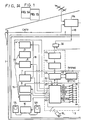
- Fig. 1 is formed of Figs. 1A and 1B drawn on two sheets of drawings so as to permit the use of a suitably large scale.
- a multi-link center 3 such as a multi-preamplifier or the like is installed within this master room 2.
- the multi-link center 3 within this master room 2 is supplied with cable TV (CATV) information and so on through a mixer 17a and cable 18.
- the audio information 16 and the video information 15 from these plurality of concentratedly installed apparatus within the master room 2 are distributed through the mixer 17a, a distributor 17b and a cable 19 to a plurality of rooms 20, 21, 22 and 23 so that these informations can be selectively viewed and listened to in these rooms by remote controllers 14a to 14c.
- the rooms 20, 21 and 22 have multi-link receivers 25, 26 and 27 provided therein, respectively.
- the multi-link receiver 25 is provided with left and right speakers 28L and 28R.
- the audio information 16 from, for example, the CD player 4 or the like can be listened to, and in the room 21 the multi-link receiver 26, left and right speakers 29L and 29R, and a TV receiver 30 are installed so that the video information 15 from, for example, the VTR 8 can be viewed by the operation of the remote controller 14b.
- the audio information 16 from, for example, the DAT 6 can be listened to through the multi-link receiver 27 and left and right speakers 30L, 30R by the operation of the remote controller 14c.
- a TV receiver 31 is installed so that CATV can be viewed thereon.
- the RF signals of CATV and so on from a two-output distributor 32 within the master room 2 are supplied to a three-output distributor 33, thereby distributed as, for example, the RF signal of the TV to the TV receiver 13 for CATV, the RF signal of FM to the tuner 7 and the RF signal of TV to the VTR 8.
- reference numeral 40 represents a frequency band of 45 MHz to 370 MHz including, for example, channels 2 to 50 of frequency-modulated (FM) CATV.
- the AV (audio visual) informations to be used in the MLS of this embodiment are located above and below the CATV band.
- the video information 15 is an analog signal which is AM and FM-modulated and located on the upper side of the CATV band
- the audio information 16 is digitized, two-phase modulated (i.e., 2PSK: phase shift keying), and located on the lower side of the CATV band.
- the audio information 16 and the video information 15 are both modulated in a frequency multiplex fashion.
- a first remote control signal 41 and a second remote control signal 42 for remote control are digitally frequency-modulated (FSK: frequency shift keying).
- the carrier frequency of the first remote control signal 41 is selected to be, for example, 16.5 MHz, and that of the second remote control signal 42 is selected to be 17.5 MHz.
- These remote control signals are modulated in a timebase multiplex fashion.
- the first remote control signal 41 is used to control from the master room 2, for example, the multi-link receivers 25, 26, 27 or the like in the respectiverooms
- the second remote control signal 42 is used for the control from the remote controllers 14a to 14c of the respective rooms to the multi-link center 3 of the master room 2.
- the remote control signal from the remote controller 14a to 14c might be a control signal of SIRCS (Sony Infrared Remote Control System) which the applicant of the present application creates and employs for the remote control of audio visual apparatus.
- SIRCS remote control signal has a format of infrared digital code system and a code format thereof is represented in Fig. 3.
- the format of one frame is normally formed of 15 bits (or 12 bits) which includes a guide pulse 36 as an identification (ID) signal for specifying the start and a binary code of 15 bits (or 12 bits) which begins at 2 degrees following this guide pulse 36.
- This binary code is formed of a data code 37 of 7 bits indicative of control function, and a merchandise code 38 of 8 bits indicative of merchandise category, following this data code 37.
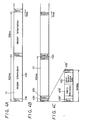
- Figs. 4A through 4C are format diagrams, respectively, of the first remote control signal 41 supplied from the multi-link center 3 to the multi-link receivers 25, 26 and 27 of the respective rooms, and the second remote control signal 42 supplied from the remote controllers 14a to 14c of the respective rooms to the multi-link center 3.
- Fig. 4A shows the format of the first remote control signal, which is formed of a synchronizing (sync.) signal 41a at the head thereof and of a next master information 41b such as data transmission room number and a transmission/reception permission flag or the like and which is repeatedly sent at every 100 ms of time.
- Fig. 4B shows the format of the second remote control signal 42, which is formed of control data 42a, 42b, ..., 42p of 1024 bits for the first room to sixteenth room, and which is repeatedly sent at every 100 ms of time.
- the data of each room as shown in Fig. 4C is formed of a sync.
- the second remote control signal 42 from the remote controllers 14a to 14c and which is distributed by the two-output distributor 32 within the master room 2 has a carrier of 17.5 MHz and undergoes RF processing in an RF circuit 43.
- the thus processed signal is then supplied to the following first decoder 44, in which data of certain bits of the second 100-ms remote control signal 42 shown in Fig. 4B is decoded and from which decoded data is derived.
- the decoded signal is supplied to the following second decoder 45, which then produces data of 64 bits of one room unit as shown in Fig. 4C.
- the output of the second decoder 45 is supplied to a microcomputer (hereinafter referred to as a CPU (central processing unit)) 47.
- a CPU central processing unit
- This CPU 47 is capable of simultaneously processing remote control signals 100-ms interval data of 16 rooms, and has a memory 46. This CPU 47 also arranges data read from the remote control signal of 64 bits at each room. If the CD player 4 and DAT 6 are found to be in the playback mode from the command state from the remote control signals 14a to 14c, then the CPU 47 raises flags on the table corresponding to the CD player 4 and the DAT 6 in the memory 46 and supplies control data with the flags raised, from parallel output terminals 49 of the CPU 47 to the CD player 4, the DAT 6 the tuner 7, the VTR 8, the main amplifier 10 and so on within 100 ms.
- This control data is the SIRCS signal of 45 ms per frame earlier noted with reference to Fig. 3.
- control data of two frames used to process one command are supplied to a plurality of electronic apparatus such as the CD player 4, the DAT 6, the tuner 7, the VTR 8, the main amplifier 10 or the like in parallel substantially simultaneously so that control data can be supplied to the plurality of electronic apparatus during 100 ms of time, as shown in Fig. 5.
- the CPU 47 in this embodiment is provided with a series output terminal 50 for SIRCS from which the remote control signal is derived because the control data cannot be supplied from the SIRCS control data output terminals 49.
- control data light-modulated is transmitted through the output terminal 50 from a light emitting element 51a, thus enabling the control data to be supplied to the deck 5 and the laser disc player 9 having no SIRCS terminal.
- the controlling time of 200 ms is required, but the waiting time upon operation can be reduced by selecting two modes at a time.
- a switch group 35 by which the series or parallel state can be selected is provided on the CPU 47, and the electronic apparatus which is desired to be controlled in series is made in ground potential by closing its corresponding switch so that the control data can be delivered in series. Also, although in Fig. 1 it is not shown that the AV informations are delivered from the electronic apparatus 4 to 9, these informations are supplied in parallel from these apparatus 4 to 9 to the multi-link center 3.
- control data is supplied to the deck 5 and the laser disc player 9 having no SIRCS terminal from the common light emitting device 51a as described above, if for the apparatus having no SIRCS terminal there are provided exclusive light emitting elements respectively, the controlling time can be reduced more.
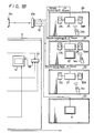
- Fig. 6 shows a second embodiment of the present invention in which the controlling time can be reduced more.
- Fig. 6 is formed of Figs. 6A and 6B drawn on two sheets of drawings so as to permit the use of a suitably large scale and in Fig. 6, like parts corresponding to those of Fig. 1 are marked with the same references and therefore need not be described in detail.
- the multi-link center 3 includes a conversion table 48 formed of a rewritable memory for the apparatus which cannot be operated by the SIRCS signal.
- the SIRCS signal is supplied to the conversion table 48, in which it is converted into control data stored therein by the operation which will be later referred to, and the thus converted control data is supplied to the corresponding apparatus.
- control data produced separately for the respective apparatus from the CPU 47 are switched by change-over switches 51 to 57 to be distributed to the path including the conversion table 48 and to the path not including the conversion table 48. Then, the output from the conversion table 48 and the control data directly supplied from the switches 51 to 57 are switched to respective single signal lines by change-over switches 61 to 67 and then transmitted through the parallel output terminals 49 to the respective apparatus as control data.
- the change-over switches 51 to 57 and the change-over switches 61 to 67 are operated in unison with each other under the control of the CPU 47, so that the change-over switches associated with the apparatus which have made operation of storing the control data are changed to the conversion table 48 side position.
- the CD player 4, the DAT 6, the tuner 7, the VTR 8 and the main amplifier 10 are the apparatus of the same maker which can be operated by the SIRCS signal and that the deck 5 and the laser disc player 9 are the apparatus of different makers which have no SIRCS terminals and which can be operated by the remote control signal of control codes different from the SIRCS signal.
- the apparatus 4, 6, 7, 8, 10 which can be operated by the SIRCS signals are directly supplied at their SIRCS signal input terminals with the control signals (SIRCS signals) produced through the parallel output terminals 49.
- the control signals produced from the parallel output terminals 49 are supplied to infrared signal light emitting units 5a, 9a which are respectively opposite the respective infrared remote control signal receiving portions of the apparatus 5, 9 and the infrared signal light emitting units 5a, 9a supply infrared signals as control data to the signal receiving portions of the apparatus.
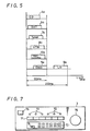
- Fig. 7 shows one example of the front panel of the multi-link center 3.
- the mode change-over switch 74 is first operated to select an operation mode of the multi-link center 3 as a learning mode. At this time, the pilot lamps 72 associated with the function by which the control codes other than the SIRCS signals are already stored in the conversion table 48 are lit, and the pilot lamps 72 associated with the function by which the control codes other than the SIRCS signal are not stored are intermittently lit.
- the control data for the deck 5 and for the laser disc player 9 must be input.
- the user pushes the function change-over switch 71 associated with the deck 5.
- the pilot lamp 72 associated with the deck 5 blinks.
- the user brings the remote controller (not shown) attached to the deck 5 and which derives a remote control signal other than the SIRCS signal close to the remote control signal receiving portion 75 and pushes the operation key of the same function of the remote controller, so that the remote controller of the deck 5 emits the corresponding remote control signal to the remote control signal receiving portion 75.
- the remote control signal received by the remote control signal receiving portion 75 is stored in the corresponding address of the conversion table 48 under the control of the CPU 47.
- the blinking pilot lamp 72 is continuously turned on.
- the pilot lamp 72 is again blinked.
- the function change-over switch 71 associated with the laser disc player 9 is pushed and then the operation key 73 and the remote controller of the laser disc player 9 are operated. After the completion of the control data storing operation, the mode change-over switch 74 is operated to bring the operation mode of the multi-link center 3 back to the normal mode.
- the control codes to be supplied from the CPU 47 to the apparatus are controlled by the switching operation of the change-over switches 51 to 57 and change-over switches 61 to 67 so as to be fed through the conversion table 48 to the parallel output terminals 49.
- the SIRCS signal is supplied to the conversion table 48, the stored control data of other codes of the same function is read from the conversion table 48, and supplied through the parallel output terminals 49.
- control data of SIRCS signal is generated from the remote controller 14 within the master room 2
- control data of SIRCS signal are generated from the remote controllers 14a to 14c within the respective rooms 20, 21, 22, 23 and fed through the above-mentioned transmission paths to the multi-link center 3
- the control data of SIRCS signal are directly supplied to the apparatus (the CD player 4, the DAT 6, the tuner 7, the VTR 8 and the main amplifier 10) which can be operated by the SIRCS signal
- the corresponding control data read from the conversion table 48 are fed to the apparatus (the deck 5 and the laser disc player 9) which can be operated by other control codes, so that the respective apparatus can be controlled by the MLS irrespective of the kinds of the control codes.
- the control signal can be processed during a reduced time. Furthermore, even when the apparatus operable by the remote control signal of control code other than the SIRCS signal is installed within the master room, such remote control signal is converted into a remote control signal associated with the apparatus, thus making it possible to control apparatus having different control codes.
Abstract
Description
- The present invention generally relates to a control system for a plurality of electronic apparatus, such as a home bus system and, more particularly, is directed to a signal transmission system.
- In recent years, a home bus system has been practically used in homes. This home bus system connects various different electronic apparatus such as, for example, a personal computer, illumination control terminals, gas leakage sensor and so on by a transmission cable and makes various controls on the apparatus. In addition, the applicant of the present application has previously proposed the Multi Link System (hereinafter simply referred to as an MLS) in which audio and video informations are distributed through wires from one room of a home to each room where the information can be selectively viewed and listened to. Japanese Patent Laid-Open Gazette No. 2-226890 describes this previously-proposed MLS which will be described below.
- Of a plurality of rooms of a house, a basement or a parlor, for example, is used as a master room. Within this master room, a plurality of electronic apparatus, for example, a CD (compact disc) player, a tape cassette deck, a VTR (video tape recorder) or the like,a multi-link center such as a multi-preamplifier or the like to which the electronic apparatus are connected and which controls the same are concentratedly installed. Whereas, multi-link receivers are installed in other rooms through cables in order that audio information and video information from the above-mentioned plurality of electronic apparatus can be listened to and viewed by means of remote controllers. Thus, by operating the remote controller provided in each of the multi-link receivers, it is possible for the user to view and listen to desired informations in each room from various electronic apparatus connected to the multi-link center in the master room.
- In the above MLS, when the multi-link center receives control signals from remote controllers from respective rooms substantially at the same time in order for the users in different rooms to listen to and view audio and video informations from a predetermined electronic apparatus installed in the master room, the multi-link center arranges these control signals and transmits in a serial fashion a CD control signal, a tape cassette deck control signal, a VTR control signal, ... to various electronic apparatus in that order by means of wires. Therefore, in order to process one command (control signal), 100 ms of time is required, and if n users operate their remote controllers within n rooms at a time, respectively, then they can view and listen to audio and video informations 100 x n ms after the transmission of the commands. Thus, the users are kept waiting for a considerably long period of time.
- Furthermore, because an electronic apparatus having no input terminal to receive a control signal through wires cannot receive the control signal from the multi-link center, such kind of electronic apparatus cannot be controlled from each room in a remote-control fashion.
- Accordingly, it is an object of the present invention to provide an improved signal transmission system in which the aforenoted shortcomings and disadvantages encountered with the prior art can be substantially eliminated.
- More specifically, it is an object of the present invention to provide a signal transmission system in which time for processing control signals from remote controllers in respective rooms by a multi-link center can be reduced considerably.
- Another object of the present invention is to provide a signal transmission system in which a multi-link system can be constructed even when electronic apparatus having no wire connection input terminals are installed wihtin a master room.
- As an aspect of the present invention, a signal transmission system in which various kinds of electronic apparatus capable of transmitting information such as audio and/or video information are concentratedly installed and in which audio and/or video informations from said electronic apparatus can be viewed and listened to in a plurality of remote spots comprises main control means for controlling those various electronic apparatus and sub-control means installed in a plurality of rooms via cables so as to properly view and listen to the above information via the main control means. When a control signal for controlling the electronic apparatus is supplied to the main control means from the sub-control means, the main control means converts the input control signal to a control signal associated with each of the electronic apparatus and supplies control signals associated with various kinds of electronic apparatus in parallel or in parallel and in series to various kinds of electronic apparatus.
- The above, and other objects, features and advantages of the present invention will become apparent in the following detailed description of illustrative embodiments thereof to be read in conjunction with the accompanying drawings, in which like reference numerals are used to identify the same or similar parts in the several views.
-
- Fig 1 (formed of Figs. 1A and 1B) is a systematic block diagram showing a first embodiment of a signal transmission system according to the present invention;
- Fig. 2 is a diagram of frequency allocation of a multi-link system of the present invention;
- Fig. 3 is a diagram showing a format of a remote control signal of an infrared digital code system used in the present invention;
- Figs. 4A through 4C are diagrams of formats, respectively, of remote control signals of the multi-link system of the present invention;
- Fig. 5 is a schematic representation used to explain a serial parallel control system of the present invention;
- Fig. 6 (formed of Figs. 6A and 6B) is a systematic diagram showing a second embodiment of the signal transmission system according to the present invention; and
- Fig. 7 is a schematic plan view of a front panel of a multi-link center used in the second embodiment of the present invention.
- Referring to the drawings in detail, and initially to Fig. 1, the MLS (multi-link system) of the present invention will be described hereinafter. In this case, Fig. 1 is formed of Figs. 1A and 1B drawn on two sheets of drawings so as to permit the use of a suitably large scale.
- As shown in Fig. 1, of a plurality of rooms of a
house 1, a basement or a parlor, for example, is used as amaster room 2, and amulti-link center 3 such as a multi-preamplifier or the like is installed within thismaster room 2. A plurality of apparatus to be driven by thismulti-link center 3, for example, aCD player 4, atape cassette deck 5, a DAT (digital audio tape recorder)deck 6, an AM-FM tuner 7, aVTR 8, alaser disc player 9, amain amplifier 10 including left andright speakers receiver 13 and so on, are concentratedly installed in themaster room 2. Even in themaster room 2, desiredaudio information 16 andvideo information 15 from these plurality of apparatus can be viewed and listened to by the operation of aremote controller 14 or the like. Themulti-link center 3 within thismaster room 2 is supplied with cable TV (CATV) information and so on through amixer 17a andcable 18. Theaudio information 16 and thevideo information 15 from these plurality of concentratedly installed apparatus within themaster room 2 are distributed through themixer 17a, adistributor 17b and acable 19 to a plurality ofrooms remote controllers 14a to 14c. Therooms multi-link receivers multi-link receiver 25 is provided with left andright speakers room 20, theaudio information 16 from, for example, theCD player 4 or the like can be listened to, and in theroom 21 themulti-link receiver 26, left andright speakers TV receiver 30 are installed so that thevideo information 15 from, for example, theVTR 8 can be viewed by the operation of theremote controller 14b. In theroom 22, theaudio information 16 from, for example, theDAT 6 can be listened to through themulti-link receiver 27 and left andright speakers room 23, aTV receiver 31 is installed so that CATV can be viewed thereon. - The RF signals of CATV and so on from a two-
output distributor 32 within themaster room 2 are supplied to a three-output distributor 33, thereby distributed as, for example, the RF signal of the TV to theTV receiver 13 for CATV, the RF signal of FM to thetuner 7 and the RF signal of TV to theVTR 8. - A frequency allocation in the MLS of this embodiment upon reception of CATV signals as external signals will be described with reference to Fig. 2.
- In Fig. 2,
reference numeral 40 represents a frequency band of 45 MHz to 370 MHz including, for example,channels 2 to 50 of frequency-modulated (FM) CATV. The AV (audio visual) informations to be used in the MLS of this embodiment are located above and below the CATV band. More specifically, thevideo information 15 is an analog signal which is AM and FM-modulated and located on the upper side of the CATV band, and theaudio information 16 is digitized, two-phase modulated (i.e., 2PSK: phase shift keying), and located on the lower side of the CATV band. Theaudio information 16 and thevideo information 15 are both modulated in a frequency multiplex fashion. A firstremote control signal 41 and a secondremote control signal 42 for remote control are digitally frequency-modulated (FSK: frequency shift keying). The carrier frequency of the firstremote control signal 41 is selected to be, for example, 16.5 MHz, and that of the secondremote control signal 42 is selected to be 17.5 MHz. These remote control signals are modulated in a timebase multiplex fashion. The firstremote control signal 41 is used to control from themaster room 2, for example, themulti-link receivers remote control signal 42 is used for the control from theremote controllers 14a to 14c of the respective rooms to themulti-link center 3 of themaster room 2. - The remote control signal from the
remote controller 14a to 14c might be a control signal of SIRCS (Sony Infrared Remote Control System) which the applicant of the present application creates and employs for the remote control of audio visual apparatus. The SIRCS remote control signal has a format of infrared digital code system and a code format thereof is represented in Fig. 3. - As shown in Fig. 3, the format of one frame (45 ms) is normally formed of 15 bits (or 12 bits) which includes a
guide pulse 36 as an identification (ID) signal for specifying the start and a binary code of 15 bits (or 12 bits) which begins at 2 degrees following thisguide pulse 36. This binary code is formed of a data code 37 of 7 bits indicative of control function, and a merchandise code 38 of 8 bits indicative of merchandise category, following this data code 37. - Figs. 4A through 4C are format diagrams, respectively, of the first
remote control signal 41 supplied from themulti-link center 3 to themulti-link receivers remote control signal 42 supplied from theremote controllers 14a to 14c of the respective rooms to themulti-link center 3. - Fig. 4A shows the format of the first remote control signal, which is formed of a synchronizing (sync.)
signal 41a at the head thereof and of a next master information 41b such as data transmission room number and a transmission/reception permission flag or the like and which is repeatedly sent at every 100 ms of time. Fig. 4B shows the format of the secondremote control signal 42, which is formed ofcontrol data signal 42a′,data 42b′ of 12 to 15 bits of the SIRCS system mentioned above, and othersecurity status data 42c′, and CRC (cyclic redundancy check) code 42d′ in that order which have 64 bits in all and are timebase-compressed. - Referring back to Fig. 1, the second
remote control signal 42 from theremote controllers 14a to 14c and which is distributed by the two-output distributor 32 within themaster room 2 has a carrier of 17.5 MHz and undergoes RF processing in anRF circuit 43. The thus processed signal is then supplied to the followingfirst decoder 44, in which data of certain bits of the second 100-msremote control signal 42 shown in Fig. 4B is decoded and from which decoded data is derived. The decoded signal is supplied to the followingsecond decoder 45, which then produces data of 64 bits of one room unit as shown in Fig. 4C. The output of thesecond decoder 45 is supplied to a microcomputer (hereinafter referred to as a CPU (central processing unit)) 47. ThisCPU 47 is capable of simultaneously processing remote control signals 100-ms interval data of 16 rooms, and has amemory 46. ThisCPU 47 also arranges data read from the remote control signal of 64 bits at each room. If theCD player 4 andDAT 6 are found to be in the playback mode from the command state from theremote control signals 14a to 14c, then theCPU 47 raises flags on the table corresponding to theCD player 4 and theDAT 6 in thememory 46 and supplies control data with the flags raised, from parallel output terminals 49 of theCPU 47 to theCD player 4, theDAT 6 thetuner 7, theVTR 8, themain amplifier 10 and so on within 100 ms. This control data is the SIRCS signal of 45 ms per frame earlier noted with reference to Fig. 3. In order to increase reliability of operation more, control data of two frames used to process one command are supplied to a plurality of electronic apparatus such as theCD player 4, theDAT 6, thetuner 7, theVTR 8, themain amplifier 10 or the like in parallel substantially simultaneously so that control data can be supplied to the plurality of electronic apparatus during 100 ms of time, as shown in Fig. 5. If now thedeck 5 and thelaser disc player 9 other than the aforenoted electronic apparatus have no terminals to which the SIRCS control signal is supplied, theCPU 47 in this embodiment is provided with aseries output terminal 50 for SIRCS from which the remote control signal is derived because the control data cannot be supplied from the SIRCS control data output terminals 49. - Since even the apparatus having no SIRCS terminal generally has a light receiving element for command, control data light-modulated is transmitted through the
output terminal 50 from alight emitting element 51a, thus enabling the control data to be supplied to thedeck 5 and thelaser disc player 9 having no SIRCS terminal. In this case, since two apparatus are controlled in series as shown in Fig. 5, the controlling time of 200 ms is required, but the waiting time upon operation can be reduced by selecting two modes at a time. - In this embodiment, a
switch group 35 by which the series or parallel state can be selected is provided on theCPU 47, and the electronic apparatus which is desired to be controlled in series is made in ground potential by closing its corresponding switch so that the control data can be delivered in series. Also, although in Fig. 1 it is not shown that the AV informations are delivered from theelectronic apparatus 4 to 9, these informations are supplied in parallel from theseapparatus 4 to 9 to themulti-link center 3. - Further, although the control data is supplied to the
deck 5 and thelaser disc player 9 having no SIRCS terminal from the commonlight emitting device 51a as described above, if for the apparatus having no SIRCS terminal there are provided exclusive light emitting elements respectively, the controlling time can be reduced more. - Fig. 6 shows a second embodiment of the present invention in which the controlling time can be reduced more. Fig. 6 is formed of Figs. 6A and 6B drawn on two sheets of drawings so as to permit the use of a suitably large scale and in Fig. 6, like parts corresponding to those of Fig. 1 are marked with the same references and therefore need not be described in detail.
- Referring to Fig. 6, the
multi-link center 3 includes a conversion table 48 formed of a rewritable memory for the apparatus which cannot be operated by the SIRCS signal. The SIRCS signal is supplied to the conversion table 48, in which it is converted into control data stored therein by the operation which will be later referred to, and the thus converted control data is supplied to the corresponding apparatus. - More specifically, the control data produced separately for the respective apparatus from the
CPU 47 are switched by change-overswitches 51 to 57 to be distributed to the path including the conversion table 48 and to the path not including the conversion table 48. Then, the output from the conversion table 48 and the control data directly supplied from theswitches 51 to 57 are switched to respective single signal lines by change-overswitches 61 to 67 and then transmitted through the parallel output terminals 49 to the respective apparatus as control data. In this case, the change-overswitches 51 to 57 and the change-overswitches 61 to 67 are operated in unison with each other under the control of theCPU 47, so that the change-over switches associated with the apparatus which have made operation of storing the control data are changed to the conversion table 48 side position. - Let it now be assumed that of the apparatus connected to the
multi-link center 3, theCD player 4, theDAT 6, thetuner 7, theVTR 8 and themain amplifier 10 are the apparatus of the same maker which can be operated by the SIRCS signal and that thedeck 5 and thelaser disc player 9 are the apparatus of different makers which have no SIRCS terminals and which can be operated by the remote control signal of control codes different from the SIRCS signal. At this time, theapparatus apparatus light emitting units apparatus light emitting units - The procedure of storing the control data in this conversion table 48 will be described with reference to Fig. 7. Fig. 7 shows one example of the front panel of the
multi-link center 3. - As Fig. 7 shows, this
multi-link center 3 comprises a panel provided with function change-overswitches 71 for selecting any one of the connected apparatus,pilot lamps 72 associated with the respective apparatus which can be switched by the function change-overswitches 71, a plurality of operation switches 73, a mode change-over switch 74 and a remote controlsignal receiving portion 75. Thismulti-link center 3 also has a pre-amplifier function, itsvolume control 76 or the like. - When the control data is to be stored, the mode change-
over switch 74 is first operated to select an operation mode of themulti-link center 3 as a learning mode. At this time, thepilot lamps 72 associated with the function by which the control codes other than the SIRCS signals are already stored in the conversion table 48 are lit, and thepilot lamps 72 associated with the function by which the control codes other than the SIRCS signal are not stored are intermittently lit. - Now assuming that no data of control codes other than the SIRCS signal is stored at all, then the control data for the
deck 5 and for thelaser disc player 9 must be input. When the control data for thedeck 5 is to be input, the user pushes the function change-overswitch 71 associated with thedeck 5. At this time, only thepilot lamp 72 associated with thedeck 5 blinks. Then, after pushing any one of theoperation keys 73 associated with the desired function to be stored, the user brings the remote controller (not shown) attached to thedeck 5 and which derives a remote control signal other than the SIRCS signal close to the remote controlsignal receiving portion 75 and pushes the operation key of the same function of the remote controller, so that the remote controller of thedeck 5 emits the corresponding remote control signal to the remote controlsignal receiving portion 75. The remote control signal received by the remote controlsignal receiving portion 75 is stored in the corresponding address of the conversion table 48 under the control of theCPU 47. In this case, when any one of theoperation keys 73 is pushed, the blinkingpilot lamp 72 is continuously turned on. When the operation of storing in the conversion table 48 is completed, thepilot lamp 72 is again blinked. - In this fashion, the control data for each function (PLAY, FAST FORWARD, REWIND, RECORD and so on) which the
deck 5 has are stored in the conversion table 48. - Moreover, similarly when the control data for the
laser disc player 9 is to be inputted, the function change-overswitch 71 associated with thelaser disc player 9 is pushed and then theoperation key 73 and the remote controller of thelaser disc player 9 are operated. After the completion of the control data storing operation, the mode change-over switch 74 is operated to bring the operation mode of themulti-link center 3 back to the normal mode. - When the data of the control code other than the SIRCS signal have been stored in the conversion table 48, the control codes to be supplied from the
CPU 47 to the apparatus (thedeck 5 and the laser disc player 9) are controlled by the switching operation of the change-overswitches 51 to 57 and change-overswitches 61 to 67 so as to be fed through the conversion table 48 to the parallel output terminals 49. When the SIRCS signal is supplied to the conversion table 48, the stored control data of other codes of the same function is read from the conversion table 48, and supplied through the parallel output terminals 49. - Thus, when the control data of SIRCS signal is generated from the
remote controller 14 within themaster room 2, and when the control data of SIRCS signal are generated from theremote controllers 14a to 14c within therespective rooms multi-link center 3, the control data of SIRCS signal are directly supplied to the apparatus (theCD player 4, theDAT 6, thetuner 7, theVTR 8 and the main amplifier 10) which can be operated by the SIRCS signal, and the corresponding control data read from the conversion table 48 are fed to the apparatus (thedeck 5 and the laser disc player 9) which can be operated by other control codes, so that the respective apparatus can be controlled by the MLS irrespective of the kinds of the control codes. - Since the signal transmission system of the present invention is constructed as described above, the control signal can be processed during a reduced time. Furthermore, even when the apparatus operable by the remote control signal of control code other than the SIRCS signal is installed within the master room, such remote control signal is converted into a remote control signal associated with the apparatus, thus making it possible to control apparatus having different control codes.
- Having described the preferred embodiments of the invention with reference to the accompanying drawings, it is to be understood that the invention is not limited to those precise embodiments and that various changes and modifications thereof could be effected by one skilled in the art without departing from the spirit or scope of the novel concepts of the invention as defined in the appended claims.
Claims (14)
- A signal transmission system in which a plurality of electronic apparatus (4 to 10) capable of transmitting audio and/or video informations are concentratedly installed and in which audio and/or video informations from said electronic apparatus (4 to 10) can be viewed and listened to in a plurality of remote spots (20 to 23), characterized in that it comprises:(a) main control means (3) connected with said plurality of electronic apparatus (4 to 10) and having means for supplying a control signal (41) in parallel or in parallel and in series to said electronic apparatus (4 to 10) so that said electronic apparatus are controlled;(b) sub-control means (25,14a; 26,14b; 27,14c) for receiving audio and/or video informations through said main control means (3) from said plurality of electronic apparatus (4 to 10) and supplying a control signal (42) to said electronic apparatus (4 to 10); and(c) transmitting means (18,19,17a,17b) for connecting said main control means (3) and said sub-control means (25,14a; 26,14b; 27,14c), transmitting the audio and/or video informations from said main control means (3) to said sub-control means (25,14a; 26,14b; 27,14c) and transmitting the control signals (42) for controlling said electronic apparatus (4 to 10) from said sub-control means (25,14a; 26,14b; 27,14c) to said main control means (3).
- A signal transmission system according to claim 1, wherein the control signal (41) for controlling said electronic apparatus (4 to 10) is supplied from said main control means (3) to said plurality of electronic apparatus through wire.
- A signal transmission system according to claim 1, wherein the control signal (41) for controlling said electronic apparatus (4 to 10) is light-modulated and transmitted from said main control means (3) to said plurality of electronic apparatus (4 to 10).
- A signal transmission system according to claim 1, wherein the control signal (41) supplied from said main control means (3) to control said plurality of electronic apparatus (4 to 10) is light-modulated and supplied to said electronic apparatus (4 to 10) and also supplied through wire to said electronic apparatus (4 to 10).
- A signal transmission system according to claim 1, wherein the control signal (41) supplied from said main control means (3) to control said electronic apparatus (4 to 10) is light-modulated and supplied to said electronic apparatus (4 to 10) or supplied through wire to said electronic apparatus.
- A signal transmission system according to claim 5, wherein said main control means (3) includes switching means (35; 51 to 57, 61 to 67) for selectively switching said control signal (41) in response to the kind of said electronic apparatus (4 to 10) connected thereto so that said control signal (41) is light-modulated and transmitted to said electronic apparatus or supplied through wire to said electronic apparatus.
- A signal transmission system according to any one of preceding claims 3, 4, 5 and 6, wherein said control signal (41) for controlling said electronic apparatus (4 to 10) is transmitted by means of an infrared signal.
- A signal transmission system according to claim 1, wherein said audio and/or video information, control signal and managing information are modulated in a frequency-multiplex fashion and transmitted between said control means (3) and said sub-control means (25,14a; 26,14b; 27,14c).
- A signal transmission system according to claim 1, characterized in that said main control means (3) has means for supplying a first control signal (41) in parallel or in parallel and in series to said electronic apparatus (4 to 10), said sub-control means (25,14a, 26,14b; 27,14c) transmits to said electronic apparatus a second control signal (42) for controlling said electronic apparatus (4 to 10), said transmitting means transmits said second signal (42) for controlling said electronic apparatus from said sub-control means (25,14a; 26,14b; 27,14c) to said main control means (3) and converting means (43 to 47) are provided in said main control means (3) for converting said second control signal (42) from said sub-control means (25,14a; 26,14b; 27,14c) to said first control signal (41).
- A signal transmission system according to claim 9, wherein said converting means includes first memory means for storing said first control signal (41) associated with said second control signal (42) and switching means for switching the normal mode into the memory mode when said first control signal (41) is stored in said memory means.
- A signal transmission system according to claim 9, wherein said main control means (3) includes switching means (35; 51 to 57, 61 to 67) for selectively switching said second control signal (42) in response to the kinds of said plurality of electronic apparatus (4 to 10) connected to said main control means (3) so that said second control signal (42) is converted into said first control signal (41).
- A signal transmission system according to claim 9, wherein at least said first control signal (41) converted by said converting means is light-modulated and transmitted to said electronic apparatus (5,9).
- A signal transmission system according to claim 11, wherein said switching means (51 to 57, 61 to 67) is controlled by a central processing unit (47).
- A signal transmission system according to claim 11, wherein said main control means (3) includes second memory means (48) for storing switched states of said switching means.
Applications Claiming Priority (4)
| Application Number | Priority Date | Filing Date | Title |
|---|---|---|---|
| JP113268/90 | 1990-04-28 | ||
| JP2113268A JP2830362B2 (en) | 1990-04-28 | 1990-04-28 | Transceiver |
| JP144888/90 | 1990-06-01 | ||
| JP2144888A JPH0437394A (en) | 1990-06-01 | 1990-06-01 | Signal processing unit |
Publications (3)
| Publication Number | Publication Date |
|---|---|
| EP0455549A2 true EP0455549A2 (en) | 1991-11-06 |
| EP0455549A3 EP0455549A3 (en) | 1992-09-16 |
| EP0455549B1 EP0455549B1 (en) | 1998-08-19 |
Family
ID=26452261
Family Applications (1)
| Application Number | Title | Priority Date | Filing Date |
|---|---|---|---|
| EP91401126A Expired - Lifetime EP0455549B1 (en) | 1990-04-28 | 1991-04-26 | A signal transmission system for remote control of electronic apparatus |
Country Status (4)
| Country | Link |
|---|---|
| US (1) | US5321846A (en) |
| EP (1) | EP0455549B1 (en) |
| KR (1) | KR100246281B1 (en) |
| DE (1) | DE69130001T2 (en) |
Cited By (1)
| Publication number | Priority date | Publication date | Assignee | Title |
|---|---|---|---|---|
| US5321846A (en) * | 1990-04-28 | 1994-06-14 | Sony Corporation | Signal transmission system with quicker response and with parallel and serial outputs |
Families Citing this family (97)
| Publication number | Priority date | Publication date | Assignee | Title |
|---|---|---|---|---|
| US6067072A (en) * | 1991-12-17 | 2000-05-23 | Sony Corporation | Audio equipment and method of displaying operating thereof |
| US5666136A (en) * | 1991-12-17 | 1997-09-09 | Sony Corporation | Audio equipment and method of displaying operation thereof |
| US5631850A (en) * | 1992-09-11 | 1997-05-20 | Sony Corporation | Audio visual equipment with a digital bus system and method for initializing and confirming connection |
| US7835989B1 (en) | 1992-12-09 | 2010-11-16 | Discovery Communications, Inc. | Electronic book alternative delivery systems |
| US7849393B1 (en) | 1992-12-09 | 2010-12-07 | Discovery Communications, Inc. | Electronic book connection to world watch live |
| US8073695B1 (en) | 1992-12-09 | 2011-12-06 | Adrea, LLC | Electronic book with voice emulation features |
| ES2152712T3 (en) | 1992-12-09 | 2001-02-01 | Discovery Communicat Inc | DISTRIBUTION SYSTEM OF TELEVISION PROGRAMS. |
| US7509270B1 (en) | 1992-12-09 | 2009-03-24 | Discovery Communications, Inc. | Electronic Book having electronic commerce features |
| JPH06217250A (en) * | 1993-01-20 | 1994-08-05 | Sony Corp | Control method for signal line of av equipment |
| US20020048448A1 (en) * | 1993-03-29 | 2002-04-25 | Microsoft Corporation | Pausing the display of a television program as a signal including the television program is received |
| US6973669B2 (en) * | 1993-03-29 | 2005-12-06 | Microsoft Corporation | Pausing television programming in response to selection of hypertext link |
| US8095949B1 (en) | 1993-12-02 | 2012-01-10 | Adrea, LLC | Electronic book with restricted access features |
| US7861166B1 (en) | 1993-12-02 | 2010-12-28 | Discovery Patent Holding, Llc | Resizing document pages to fit available hardware screens |
| US7865567B1 (en) | 1993-12-02 | 2011-01-04 | Discovery Patent Holdings, Llc | Virtual on-demand electronic book |
| US9053640B1 (en) | 1993-12-02 | 2015-06-09 | Adrea, LLC | Interactive electronic book |
| US8661477B2 (en) | 1994-10-12 | 2014-02-25 | Touchtunes Music Corporation | System for distributing and selecting audio and video information and method implemented by said system |
| US7424731B1 (en) | 1994-10-12 | 2008-09-09 | Touchtunes Music Corporation | Home digital audiovisual information recording and playback system |
| CA2201909C (en) | 1994-10-12 | 2006-05-02 | Technical Maintenance Corporation | Intelligent digital audiovisual playback system |
| US7188352B2 (en) | 1995-07-11 | 2007-03-06 | Touchtunes Music Corporation | Intelligent digital audiovisual playback system |
| US5710712A (en) * | 1994-11-22 | 1998-01-20 | Motorola, Inc. | Processor system and method for appliances |
| US7917922B1 (en) * | 1995-06-08 | 2011-03-29 | Schwab Barry H | Video input switching and signal processing apparatus |
| FR2736787B1 (en) * | 1995-07-11 | 1997-08-08 | Alcatel Business Systems | COMMUNICATION SYSTEM AND CORRESPONDING EQUIPMENT FOR SUBSCRIBER INSTALLATION |
| US6177963B1 (en) | 1996-04-22 | 2001-01-23 | Multiplex Technology, Inc. | Video signal distribution system |
| FR2753868A1 (en) | 1996-09-25 | 1998-03-27 | Technical Maintenance Corp | METHOD FOR SELECTING A RECORDING ON AN AUDIOVISUAL DIGITAL REPRODUCTION SYSTEM AND SYSTEM FOR IMPLEMENTING THE METHOD |
| JP3658896B2 (en) * | 1996-11-26 | 2005-06-08 | ソニー株式会社 | Information signal transmission system, playback device and display device |
| US20030192053A1 (en) * | 1997-02-19 | 2003-10-09 | Next Level Communications, Inc. | Method and apparatus for transmitting wireless signals over media |
| US20040083493A1 (en) * | 1997-02-19 | 2004-04-29 | Next Level Communications, Inc. | Transmitting caller ID within a digital stream |
| US5936667A (en) * | 1997-05-13 | 1999-08-10 | Sony Corporation | System and method for testing and updating stored content of a remote transmitter for an entertainment system |
| FR2769165B1 (en) | 1997-09-26 | 2002-11-29 | Technical Maintenance Corp | WIRELESS SYSTEM WITH DIGITAL TRANSMISSION FOR SPEAKERS |
| US20030035556A1 (en) * | 1997-11-18 | 2003-02-20 | Jerry Curtis | Audio distribution system |
| FR2781582B1 (en) | 1998-07-21 | 2001-01-12 | Technical Maintenance Corp | SYSTEM FOR DOWNLOADING OBJECTS OR FILES FOR SOFTWARE UPDATE |
| FR2781580B1 (en) | 1998-07-22 | 2000-09-22 | Technical Maintenance Corp | SOUND CONTROL CIRCUIT FOR INTELLIGENT DIGITAL AUDIOVISUAL REPRODUCTION SYSTEM |
| FR2781591B1 (en) | 1998-07-22 | 2000-09-22 | Technical Maintenance Corp | AUDIOVISUAL REPRODUCTION SYSTEM |
| US8028318B2 (en) | 1999-07-21 | 2011-09-27 | Touchtunes Music Corporation | Remote control unit for activating and deactivating means for payment and for displaying payment status |
| FR2781593B1 (en) * | 1998-07-22 | 2001-01-12 | Technical Maintenance Corp | REMOTE CONTROL FOR INTELLIGENT DIGITAL AUDIOVISUAL REPRODUCTION SYSTEM |
| US6189148B1 (en) * | 1999-01-28 | 2001-02-13 | Douglas G. Brown | Methods and circuits using frequency shift keying modulation to transfer data over transmission lines simultaneous with television signals |
| US8726330B2 (en) | 1999-02-22 | 2014-05-13 | Touchtunes Music Corporation | Intelligent digital audiovisual playback system |
| US6263503B1 (en) * | 1999-05-26 | 2001-07-17 | Neal Margulis | Method for effectively implementing a wireless television system |
| US8266657B2 (en) * | 2001-03-15 | 2012-09-11 | Sling Media Inc. | Method for effectively implementing a multi-room television system |
| FR2796482B1 (en) | 1999-07-16 | 2002-09-06 | Touchtunes Music Corp | REMOTE MANAGEMENT SYSTEM FOR AT LEAST ONE AUDIOVISUAL INFORMATION REPRODUCING DEVICE |
| US6526581B1 (en) * | 1999-08-03 | 2003-02-25 | Ucentric Holdings, Llc | Multi-service in-home network with an open interface |
| FR2805377B1 (en) | 2000-02-23 | 2003-09-12 | Touchtunes Music Corp | EARLY ORDERING PROCESS FOR A SELECTION, DIGITAL SYSTEM AND JUKE-BOX FOR IMPLEMENTING THE METHOD |
| FR2805060B1 (en) | 2000-02-16 | 2005-04-08 | Touchtunes Music Corp | METHOD FOR RECEIVING FILES DURING DOWNLOAD |
| FR2805072B1 (en) | 2000-02-16 | 2002-04-05 | Touchtunes Music Corp | METHOD FOR ADJUSTING THE SOUND VOLUME OF A DIGITAL SOUND RECORDING |
| US6842459B1 (en) | 2000-04-19 | 2005-01-11 | Serconet Ltd. | Network combining wired and non-wired segments |
| FR2808906B1 (en) | 2000-05-10 | 2005-02-11 | Touchtunes Music Corp | DEVICE AND METHOD FOR REMOTELY MANAGING A NETWORK OF AUDIOVISUAL INFORMATION REPRODUCTION SYSTEMS |
| FR2811175B1 (en) | 2000-06-29 | 2002-12-27 | Touchtunes Music Corp | AUDIOVISUAL INFORMATION DISTRIBUTION METHOD AND AUDIOVISUAL INFORMATION DISTRIBUTION SYSTEM |
| FR2811114B1 (en) | 2000-06-29 | 2002-12-27 | Touchtunes Music Corp | DEVICE AND METHOD FOR COMMUNICATION BETWEEN A SYSTEM FOR REPRODUCING AUDIOVISUAL INFORMATION AND AN ELECTRONIC ENTERTAINMENT MACHINE |
| FR2814085B1 (en) | 2000-09-15 | 2005-02-11 | Touchtunes Music Corp | ENTERTAINMENT METHOD BASED ON MULTIPLE CHOICE COMPETITION GAMES |
| US7690017B2 (en) * | 2001-05-03 | 2010-03-30 | Mitsubishi Digital Electronics America, Inc. | Control system and user interface for network of input devices |
| US8291457B2 (en) | 2001-05-24 | 2012-10-16 | Vixs Systems, Inc. | Channel selection in a multimedia system |
| US20090031419A1 (en) | 2001-05-24 | 2009-01-29 | Indra Laksono | Multimedia system and server and methods for use therewith |
| US7107608B2 (en) * | 2001-10-01 | 2006-09-12 | Microsoft Corporation | Remote task scheduling for a set top box |
| IL161190A0 (en) | 2001-10-11 | 2004-08-31 | Serconet Ltd | Outlet with analog signal adapter, method for use thereof and a network using said outlet |
| KR100454385B1 (en) | 2002-02-25 | 2004-11-05 | 이용구 | Toilet articles containing powder chemical |
| US8103589B2 (en) | 2002-09-16 | 2012-01-24 | Touchtunes Music Corporation | Digital downloading jukebox system with central and local music servers |
| US7822687B2 (en) | 2002-09-16 | 2010-10-26 | Francois Brillon | Jukebox with customizable avatar |
| US10373420B2 (en) | 2002-09-16 | 2019-08-06 | Touchtunes Music Corporation | Digital downloading jukebox with enhanced communication features |
| US9646339B2 (en) | 2002-09-16 | 2017-05-09 | Touchtunes Music Corporation | Digital downloading jukebox system with central and local music servers |
| US8332895B2 (en) | 2002-09-16 | 2012-12-11 | Touchtunes Music Corporation | Digital downloading jukebox system with user-tailored music management, communications, and other tools |
| US11029823B2 (en) | 2002-09-16 | 2021-06-08 | Touchtunes Music Corporation | Jukebox with customizable avatar |
| US8584175B2 (en) | 2002-09-16 | 2013-11-12 | Touchtunes Music Corporation | Digital downloading jukebox system with user-tailored music management, communications, and other tools |
| US8151304B2 (en) | 2002-09-16 | 2012-04-03 | Touchtunes Music Corporation | Digital downloading jukebox system with user-tailored music management, communications, and other tools |
| IL152824A (en) | 2002-11-13 | 2012-05-31 | Mosaid Technologies Inc | Addressable outlet and a network using same |
| IL157787A (en) * | 2003-09-07 | 2010-12-30 | Mosaid Technologies Inc | Modular outlet for data communications network |
| IL159838A0 (en) | 2004-01-13 | 2004-06-20 | Yehuda Binder | Information device |
| IL160417A (en) * | 2004-02-16 | 2011-04-28 | Mosaid Technologies Inc | Outlet add-on module |
| IL161869A (en) | 2004-05-06 | 2014-05-28 | Serconet Ltd | System and method for carrying a wireless based signal over wiring |
| US8346605B2 (en) * | 2004-06-07 | 2013-01-01 | Sling Media, Inc. | Management of shared media content |
| US8099755B2 (en) * | 2004-06-07 | 2012-01-17 | Sling Media Pvt. Ltd. | Systems and methods for controlling the encoding of a media stream |
| US7917932B2 (en) * | 2005-06-07 | 2011-03-29 | Sling Media, Inc. | Personal video recorder functionality for placeshifting systems |
| KR100916274B1 (en) * | 2004-06-07 | 2009-09-10 | 슬링 미디어 인코퍼레이티드 | Personal media broadcasting system |
| US7769756B2 (en) | 2004-06-07 | 2010-08-03 | Sling Media, Inc. | Selection and presentation of context-relevant supplemental content and advertising |
| US9998802B2 (en) * | 2004-06-07 | 2018-06-12 | Sling Media LLC | Systems and methods for creating variable length clips from a media stream |
| US7975062B2 (en) | 2004-06-07 | 2011-07-05 | Sling Media, Inc. | Capturing and sharing media content |
| JP3824004B2 (en) * | 2005-03-03 | 2006-09-20 | オンキヨー株式会社 | Command conversion device |
| US7813451B2 (en) | 2006-01-11 | 2010-10-12 | Mobileaccess Networks Ltd. | Apparatus and method for frequency shifting of a wireless signal and systems using frequency shifting |
| US9330529B2 (en) | 2007-01-17 | 2016-05-03 | Touchtunes Music Corporation | Game terminal configured for interaction with jukebox device systems including same, and/or associated methods |
| US9171419B2 (en) | 2007-01-17 | 2015-10-27 | Touchtunes Music Corporation | Coin operated entertainment system |
| US9953481B2 (en) | 2007-03-26 | 2018-04-24 | Touchtunes Music Corporation | Jukebox with associated video server |
| US10290006B2 (en) | 2008-08-15 | 2019-05-14 | Touchtunes Music Corporation | Digital signage and gaming services to comply with federal and state alcohol and beverage laws and regulations |
| US8332887B2 (en) | 2008-01-10 | 2012-12-11 | Touchtunes Music Corporation | System and/or methods for distributing advertisements from a central advertisement network to a peripheral device via a local advertisement server |
| US8594133B2 (en) | 2007-10-22 | 2013-11-26 | Corning Mobileaccess Ltd. | Communication system using low bandwidth wires |
| US8175649B2 (en) | 2008-06-20 | 2012-05-08 | Corning Mobileaccess Ltd | Method and system for real time control of an active antenna over a distributed antenna system |
| US8849435B2 (en) | 2008-07-09 | 2014-09-30 | Touchtunes Music Corporation | Digital downloading jukebox with revenue-enhancing features |
| EP2399141A4 (en) | 2009-02-08 | 2012-08-01 | Corning Mobileaccess Ltd | Communication system using cables carrying ethernet signals |
| US9292166B2 (en) | 2009-03-18 | 2016-03-22 | Touchtunes Music Corporation | Digital jukebox device with improved karaoke-related user interfaces, and associated methods |
| US10564804B2 (en) | 2009-03-18 | 2020-02-18 | Touchtunes Music Corporation | Digital jukebox device with improved user interfaces, and associated methods |
| US10719149B2 (en) | 2009-03-18 | 2020-07-21 | Touchtunes Music Corporation | Digital jukebox device with improved user interfaces, and associated methods |
| CN106056367A (en) | 2009-03-18 | 2016-10-26 | 踏途音乐公司 | Entertainment system and related social networking system |
| JP5571200B2 (en) | 2010-01-26 | 2014-08-13 | タッチチューンズ ミュージック コーポレイション | Digital jukebox device with improved user interface and related techniques |
| CA2971002A1 (en) | 2011-09-18 | 2013-03-21 | Touchtunes Music Corporation | Digital jukebox device with karaoke and/or photo booth features, and associated methods |
| US11151224B2 (en) | 2012-01-09 | 2021-10-19 | Touchtunes Music Corporation | Systems and/or methods for monitoring audio inputs to jukebox devices |
| EP2829152A2 (en) | 2012-03-23 | 2015-01-28 | Corning Optical Communications Wireless Ltd. | Radio-frequency integrated circuit (rfic) chip(s) for providing distributed antenna system functionalities, and related components, systems, and methods |
| WO2015070070A1 (en) | 2013-11-07 | 2015-05-14 | Touchtunes Music Corporation | Techniques for generating electronic menu graphical user interface layouts for use in connection with electronic devices |
| TWI722981B (en) | 2014-03-25 | 2021-04-01 | 美商觸控調諧音樂公司 | Digital jukebox device with improved user interfaces, and associated methods |
| US9184960B1 (en) | 2014-09-25 | 2015-11-10 | Corning Optical Communications Wireless Ltd | Frequency shifting a communications signal(s) in a multi-frequency distributed antenna system (DAS) to avoid or reduce frequency interference |
Citations (2)
| Publication number | Priority date | Publication date | Assignee | Title |
|---|---|---|---|---|
| GB2191643A (en) * | 1986-06-02 | 1987-12-16 | Sony Corp | Remote control systems |
| US4885803A (en) * | 1987-03-17 | 1989-12-05 | Lawrence W. Hermann | System and method for controlling a plurality of electronic entertainment devices |
Family Cites Families (7)
| Publication number | Priority date | Publication date | Assignee | Title |
|---|---|---|---|---|
| JPS562789A (en) * | 1979-06-21 | 1981-01-13 | Pioneer Electronic Corp | Line remote monitor method in catv system |
| US4381522A (en) * | 1980-12-01 | 1983-04-26 | Adams-Russell Co., Inc. | Selective viewing |
| US4769833A (en) * | 1986-03-31 | 1988-09-06 | American Telephone And Telegraph Company | Wideband switching system |
| JP2722450B2 (en) * | 1987-02-25 | 1998-03-04 | ソニー株式会社 | Central control device |
| JPS647791A (en) * | 1987-06-30 | 1989-01-11 | Nec Corp | Multiscreen video conference method and device therefor |
| JP2976434B2 (en) * | 1989-02-28 | 1999-11-10 | ソニー株式会社 | Control signal transmission system |
| US5321846A (en) * | 1990-04-28 | 1994-06-14 | Sony Corporation | Signal transmission system with quicker response and with parallel and serial outputs |
-
1991
- 1991-04-19 US US07/687,749 patent/US5321846A/en not_active Expired - Lifetime
- 1991-04-26 KR KR1019910006739A patent/KR100246281B1/en not_active IP Right Cessation
- 1991-04-26 DE DE69130001T patent/DE69130001T2/en not_active Expired - Lifetime
- 1991-04-26 EP EP91401126A patent/EP0455549B1/en not_active Expired - Lifetime
Patent Citations (2)
| Publication number | Priority date | Publication date | Assignee | Title |
|---|---|---|---|---|
| GB2191643A (en) * | 1986-06-02 | 1987-12-16 | Sony Corp | Remote control systems |
| US4885803A (en) * | 1987-03-17 | 1989-12-05 | Lawrence W. Hermann | System and method for controlling a plurality of electronic entertainment devices |
Non-Patent Citations (1)
| Title |
|---|
| SYMPOSIUM RECORD,15TH INTERNAT. TV SYMPOSIUM 11 June 1987, MONTREUX,CH pages 165 - 173; HOFFMANN: 'Cable, Television, and the Consumer Electronic Bus' * |
Cited By (1)
| Publication number | Priority date | Publication date | Assignee | Title |
|---|---|---|---|---|
| US5321846A (en) * | 1990-04-28 | 1994-06-14 | Sony Corporation | Signal transmission system with quicker response and with parallel and serial outputs |
Also Published As
| Publication number | Publication date |
|---|---|
| US5321846A (en) | 1994-06-14 |
| EP0455549B1 (en) | 1998-08-19 |
| DE69130001T2 (en) | 1999-04-01 |
| EP0455549A3 (en) | 1992-09-16 |
| DE69130001D1 (en) | 1998-09-24 |
| KR100246281B1 (en) | 2000-03-15 |
Similar Documents
| Publication | Publication Date | Title |
|---|---|---|
| US5321846A (en) | Signal transmission system with quicker response and with parallel and serial outputs | |
| US5193208A (en) | Signal transmission system | |
| EP0124331B2 (en) | Remote control transmitter arrangement for one or more television devices | |
| US5341166A (en) | System for controlling selected devices having unique sets of control codes | |
| US5959539A (en) | Apparatus for the remote control of electronic devices with key allocation | |
| US5255180A (en) | Control apparatus for systematically operating audio and/or video sets | |
| US5828417A (en) | Television receiver with on screen display for reserving programs to be recorded or viewed | |
| US7821377B2 (en) | Remote controller, equipment operation system, and remote control method | |
| EP0917767B1 (en) | A method for remotely controlling a plurality of apparatus using a single remote control device | |
| HU207918B (en) | Remote control control system | |
| CN1073820A (en) | The ON/OFF control of VCR cable converter unit | |
| US6604235B1 (en) | Operating system upgrading | |
| GB2193608A (en) | Video source selecting systems | |
| US6492909B1 (en) | Audio signal processing apparatus | |
| JPH07307084A (en) | Automaticaly settable videocassette recorder | |
| CN1075838A (en) | Be coupled to the automatic detection of cassette tape video recorder cable converter unit | |
| KR100201447B1 (en) | Signal transmission system for a home network | |
| JP2687392B2 (en) | Remote control device | |
| JPS6375805A (en) | Remote controller | |
| JP2830362B2 (en) | Transceiver | |
| JPH0652664A (en) | Control device | |
| JPH0437394A (en) | Signal processing unit | |
| JP2913772B2 (en) | Home bus system, receiving device and transmitting device | |
| JPH0410279B2 (en) | ||
| JP2000242991A (en) | Broadcast receiver |
Legal Events
| Date | Code | Title | Description |
|---|---|---|---|
| PUAI | Public reference made under article 153(3) epc to a published international application that has entered the european phase |
Free format text: ORIGINAL CODE: 0009012 |
|
| AK | Designated contracting states |
Kind code of ref document: A2 Designated state(s): DE FR GB IT |
|
| PUAL | Search report despatched |
Free format text: ORIGINAL CODE: 0009013 |
|
| AK | Designated contracting states |
Kind code of ref document: A3 Designated state(s): DE FR GB IT |
|
| 17P | Request for examination filed |
Effective date: 19930304 |
|
| 17Q | First examination report despatched |
Effective date: 19951221 |
|
| GRAG | Despatch of communication of intention to grant |
Free format text: ORIGINAL CODE: EPIDOS AGRA |
|
| GRAG | Despatch of communication of intention to grant |
Free format text: ORIGINAL CODE: EPIDOS AGRA |
|
| GRAH | Despatch of communication of intention to grant a patent |
Free format text: ORIGINAL CODE: EPIDOS IGRA |
|
| GRAH | Despatch of communication of intention to grant a patent |
Free format text: ORIGINAL CODE: EPIDOS IGRA |
|
| GRAA | (expected) grant |
Free format text: ORIGINAL CODE: 0009210 |
|
| AK | Designated contracting states |
Kind code of ref document: B1 Designated state(s): DE FR GB IT |
|
| REF | Corresponds to: |
Ref document number: 69130001 Country of ref document: DE Date of ref document: 19980924 |
|
| ET | Fr: translation filed | ||
| PLBQ | Unpublished change to opponent data |
Free format text: ORIGINAL CODE: EPIDOS OPPO |
|
| PLBI | Opposition filed |
Free format text: ORIGINAL CODE: 0009260 |
|
| PLAB | Opposition data, opponent's data or that of the opponent's representative modified |
Free format text: ORIGINAL CODE: 0009299OPPO |
|
| PLBF | Reply of patent proprietor to notice(s) of opposition |
Free format text: ORIGINAL CODE: EPIDOS OBSO |
|
| 26 | Opposition filed |
Opponent name: INTERESSENGEMEINSCHAFT FUER RUNDFUNKSCHUTZRECHTE E Effective date: 19990518 |
|
| R26 | Opposition filed (corrected) |
Opponent name: INTERESSENGEMEINSCHAFT FUER RUNDFUNKSCHUTZRECHTE G Effective date: 19990518 |
|
| PLBF | Reply of patent proprietor to notice(s) of opposition |
Free format text: ORIGINAL CODE: EPIDOS OBSO |
|
| PLBF | Reply of patent proprietor to notice(s) of opposition |
Free format text: ORIGINAL CODE: EPIDOS OBSO |
|
| PLBO | Opposition rejected |
Free format text: ORIGINAL CODE: EPIDOS REJO |
|
| PLBN | Opposition rejected |
Free format text: ORIGINAL CODE: 0009273 |
|
| STAA | Information on the status of an ep patent application or granted ep patent |
Free format text: STATUS: OPPOSITION REJECTED |
|
| REG | Reference to a national code |
Ref country code: GB Ref legal event code: IF02 |
|
| 27O | Opposition rejected |
Effective date: 20010713 |
|
| REG | Reference to a national code |
Ref country code: GB Ref legal event code: 746 Effective date: 20091124 |
|
| PGFP | Annual fee paid to national office [announced via postgrant information from national office to epo] |
Ref country code: GB Payment date: 20100331 Year of fee payment: 20 |
|
| PGFP | Annual fee paid to national office [announced via postgrant information from national office to epo] |
Ref country code: FR Payment date: 20100506 Year of fee payment: 20 |
|
| PGFP | Annual fee paid to national office [announced via postgrant information from national office to epo] |
Ref country code: DE Payment date: 20100423 Year of fee payment: 20 Ref country code: IT Payment date: 20100426 Year of fee payment: 20 |
|
| REG | Reference to a national code |
Ref country code: DE Ref legal event code: R071 Ref document number: 69130001 Country of ref document: DE |
|
| REG | Reference to a national code |
Ref country code: GB Ref legal event code: PE20 Expiry date: 20110425 |
|
| PG25 | Lapsed in a contracting state [announced via postgrant information from national office to epo] |
Ref country code: GB Free format text: LAPSE BECAUSE OF EXPIRATION OF PROTECTION Effective date: 20110425 |
|
| PG25 | Lapsed in a contracting state [announced via postgrant information from national office to epo] |
Ref country code: DE Free format text: LAPSE BECAUSE OF EXPIRATION OF PROTECTION Effective date: 20110426 |