EP0456095A2 - Scanning arrangement - Google Patents
Scanning arrangement Download PDFInfo
- Publication number
- EP0456095A2 EP0456095A2 EP91107037A EP91107037A EP0456095A2 EP 0456095 A2 EP0456095 A2 EP 0456095A2 EP 91107037 A EP91107037 A EP 91107037A EP 91107037 A EP91107037 A EP 91107037A EP 0456095 A2 EP0456095 A2 EP 0456095A2
- Authority
- EP
- European Patent Office
- Prior art keywords
- component
- indicia
- scan
- arrangement according
- end positions
- Prior art date
- Legal status (The legal status is an assumption and is not a legal conclusion. Google has not performed a legal analysis and makes no representation as to the accuracy of the status listed.)
- Granted
Links
- 230000033001 locomotion Effects 0.000 claims description 40
- 230000000694 effects Effects 0.000 claims description 28
- 238000001579 optical reflectometry Methods 0.000 claims description 17
- 230000004044 response Effects 0.000 claims description 12
- 238000000034 method Methods 0.000 claims description 11
- 230000005484 gravity Effects 0.000 claims description 5
- 239000000463 material Substances 0.000 description 8
- 239000002184 metal Substances 0.000 description 7
- 229910052751 metal Inorganic materials 0.000 description 7
- 230000010355 oscillation Effects 0.000 description 7
- 230000003534 oscillatory effect Effects 0.000 description 7
- 238000010276 construction Methods 0.000 description 6
- 239000011888 foil Substances 0.000 description 5
- 230000003287 optical effect Effects 0.000 description 5
- XEEYBQQBJWHFJM-UHFFFAOYSA-N Iron Chemical group [Fe] XEEYBQQBJWHFJM-UHFFFAOYSA-N 0.000 description 4
- 230000003993 interaction Effects 0.000 description 4
- 230000005540 biological transmission Effects 0.000 description 3
- 230000009471 action Effects 0.000 description 2
- 230000008901 benefit Effects 0.000 description 2
- 239000007769 metal material Substances 0.000 description 2
- 239000004033 plastic Substances 0.000 description 2
- 230000001846 repelling effect Effects 0.000 description 2
- 230000035939 shock Effects 0.000 description 2
- 238000010408 sweeping Methods 0.000 description 2
- 239000006096 absorbing agent Substances 0.000 description 1
- 230000006978 adaptation Effects 0.000 description 1
- 238000005452 bending Methods 0.000 description 1
- 150000001875 compounds Chemical class 0.000 description 1
- 238000005336 cracking Methods 0.000 description 1
- 238000013500 data storage Methods 0.000 description 1
- 230000009849 deactivation Effects 0.000 description 1
- 230000005284 excitation Effects 0.000 description 1
- 230000007246 mechanism Effects 0.000 description 1
- 150000002739 metals Chemical class 0.000 description 1
- 238000012986 modification Methods 0.000 description 1
- 230000004048 modification Effects 0.000 description 1
- 229910052755 nonmetal Inorganic materials 0.000 description 1
- 150000002843 nonmetals Chemical class 0.000 description 1
- 230000000737 periodic effect Effects 0.000 description 1
- 208000003580 polydactyly Diseases 0.000 description 1
- 230000003252 repetitive effect Effects 0.000 description 1
Images


Classifications
-
- G—PHYSICS
- G06—COMPUTING; CALCULATING OR COUNTING
- G06K—GRAPHICAL DATA READING; PRESENTATION OF DATA; RECORD CARRIERS; HANDLING RECORD CARRIERS
- G06K7/00—Methods or arrangements for sensing record carriers, e.g. for reading patterns
- G06K7/10—Methods or arrangements for sensing record carriers, e.g. for reading patterns by electromagnetic radiation, e.g. optical sensing; by corpuscular radiation
- G06K7/10544—Methods or arrangements for sensing record carriers, e.g. for reading patterns by electromagnetic radiation, e.g. optical sensing; by corpuscular radiation by scanning of the records by radiation in the optical part of the electromagnetic spectrum
- G06K7/10821—Methods or arrangements for sensing record carriers, e.g. for reading patterns by electromagnetic radiation, e.g. optical sensing; by corpuscular radiation by scanning of the records by radiation in the optical part of the electromagnetic spectrum further details of bar or optical code scanning devices
- G06K7/10861—Methods or arrangements for sensing record carriers, e.g. for reading patterns by electromagnetic radiation, e.g. optical sensing; by corpuscular radiation by scanning of the records by radiation in the optical part of the electromagnetic spectrum further details of bar or optical code scanning devices sensing of data fields affixed to objects or articles, e.g. coded labels
- G06K7/10871—Methods or arrangements for sensing record carriers, e.g. for reading patterns by electromagnetic radiation, e.g. optical sensing; by corpuscular radiation by scanning of the records by radiation in the optical part of the electromagnetic spectrum further details of bar or optical code scanning devices sensing of data fields affixed to objects or articles, e.g. coded labels randomly oriented data-fields, code-marks therefore, e.g. concentric circles-code
-
- G—PHYSICS
- G06—COMPUTING; CALCULATING OR COUNTING
- G06K—GRAPHICAL DATA READING; PRESENTATION OF DATA; RECORD CARRIERS; HANDLING RECORD CARRIERS
- G06K7/00—Methods or arrangements for sensing record carriers, e.g. for reading patterns
- G06K7/10—Methods or arrangements for sensing record carriers, e.g. for reading patterns by electromagnetic radiation, e.g. optical sensing; by corpuscular radiation
- G06K7/10544—Methods or arrangements for sensing record carriers, e.g. for reading patterns by electromagnetic radiation, e.g. optical sensing; by corpuscular radiation by scanning of the records by radiation in the optical part of the electromagnetic spectrum
- G06K7/10554—Moving beam scanning
- G06K7/10564—Light sources
- G06K7/10584—Source control
-
- G—PHYSICS
- G06—COMPUTING; CALCULATING OR COUNTING
- G06K—GRAPHICAL DATA READING; PRESENTATION OF DATA; RECORD CARRIERS; HANDLING RECORD CARRIERS
- G06K7/00—Methods or arrangements for sensing record carriers, e.g. for reading patterns
- G06K7/10—Methods or arrangements for sensing record carriers, e.g. for reading patterns by electromagnetic radiation, e.g. optical sensing; by corpuscular radiation
- G06K7/10544—Methods or arrangements for sensing record carriers, e.g. for reading patterns by electromagnetic radiation, e.g. optical sensing; by corpuscular radiation by scanning of the records by radiation in the optical part of the electromagnetic spectrum
- G06K7/10554—Moving beam scanning
- G06K7/10594—Beam path
- G06K7/10603—Basic scanning using moving elements
- G06K7/10633—Basic scanning using moving elements by oscillation
- G06K7/10643—Activating means
- G06K7/10653—Activating means using flexible or piezoelectric means
-
- G—PHYSICS
- G06—COMPUTING; CALCULATING OR COUNTING
- G06K—GRAPHICAL DATA READING; PRESENTATION OF DATA; RECORD CARRIERS; HANDLING RECORD CARRIERS
- G06K7/00—Methods or arrangements for sensing record carriers, e.g. for reading patterns
- G06K7/10—Methods or arrangements for sensing record carriers, e.g. for reading patterns by electromagnetic radiation, e.g. optical sensing; by corpuscular radiation
- G06K7/10544—Methods or arrangements for sensing record carriers, e.g. for reading patterns by electromagnetic radiation, e.g. optical sensing; by corpuscular radiation by scanning of the records by radiation in the optical part of the electromagnetic spectrum
- G06K7/10554—Moving beam scanning
- G06K7/10594—Beam path
- G06K7/10603—Basic scanning using moving elements
- G06K7/10673—Parallel lines
-
- G—PHYSICS
- G06—COMPUTING; CALCULATING OR COUNTING
- G06K—GRAPHICAL DATA READING; PRESENTATION OF DATA; RECORD CARRIERS; HANDLING RECORD CARRIERS
- G06K7/00—Methods or arrangements for sensing record carriers, e.g. for reading patterns
- G06K7/10—Methods or arrangements for sensing record carriers, e.g. for reading patterns by electromagnetic radiation, e.g. optical sensing; by corpuscular radiation
- G06K7/10544—Methods or arrangements for sensing record carriers, e.g. for reading patterns by electromagnetic radiation, e.g. optical sensing; by corpuscular radiation by scanning of the records by radiation in the optical part of the electromagnetic spectrum
- G06K7/10554—Moving beam scanning
- G06K7/10594—Beam path
- G06K7/10683—Arrangement of fixed elements
- G06K7/10693—Arrangement of fixed elements for omnidirectional scanning
-
- G—PHYSICS
- G06—COMPUTING; CALCULATING OR COUNTING
- G06K—GRAPHICAL DATA READING; PRESENTATION OF DATA; RECORD CARRIERS; HANDLING RECORD CARRIERS
- G06K7/00—Methods or arrangements for sensing record carriers, e.g. for reading patterns
- G06K7/10—Methods or arrangements for sensing record carriers, e.g. for reading patterns by electromagnetic radiation, e.g. optical sensing; by corpuscular radiation
- G06K7/10544—Methods or arrangements for sensing record carriers, e.g. for reading patterns by electromagnetic radiation, e.g. optical sensing; by corpuscular radiation by scanning of the records by radiation in the optical part of the electromagnetic spectrum
- G06K7/10792—Special measures in relation to the object to be scanned
- G06K7/10801—Multidistance reading
- G06K7/10811—Focalisation
-
- G—PHYSICS
- G06—COMPUTING; CALCULATING OR COUNTING
- G06K—GRAPHICAL DATA READING; PRESENTATION OF DATA; RECORD CARRIERS; HANDLING RECORD CARRIERS
- G06K7/00—Methods or arrangements for sensing record carriers, e.g. for reading patterns
- G06K7/10—Methods or arrangements for sensing record carriers, e.g. for reading patterns by electromagnetic radiation, e.g. optical sensing; by corpuscular radiation
- G06K7/10544—Methods or arrangements for sensing record carriers, e.g. for reading patterns by electromagnetic radiation, e.g. optical sensing; by corpuscular radiation by scanning of the records by radiation in the optical part of the electromagnetic spectrum
- G06K7/10821—Methods or arrangements for sensing record carriers, e.g. for reading patterns by electromagnetic radiation, e.g. optical sensing; by corpuscular radiation by scanning of the records by radiation in the optical part of the electromagnetic spectrum further details of bar or optical code scanning devices
- G06K7/10851—Circuits for pulse shaping, amplifying, eliminating noise signals, checking the function of the sensing device
-
- G—PHYSICS
- G06—COMPUTING; CALCULATING OR COUNTING
- G06K—GRAPHICAL DATA READING; PRESENTATION OF DATA; RECORD CARRIERS; HANDLING RECORD CARRIERS
- G06K7/00—Methods or arrangements for sensing record carriers, e.g. for reading patterns
- G06K7/10—Methods or arrangements for sensing record carriers, e.g. for reading patterns by electromagnetic radiation, e.g. optical sensing; by corpuscular radiation
- G06K7/10544—Methods or arrangements for sensing record carriers, e.g. for reading patterns by electromagnetic radiation, e.g. optical sensing; by corpuscular radiation by scanning of the records by radiation in the optical part of the electromagnetic spectrum
- G06K7/10821—Methods or arrangements for sensing record carriers, e.g. for reading patterns by electromagnetic radiation, e.g. optical sensing; by corpuscular radiation by scanning of the records by radiation in the optical part of the electromagnetic spectrum further details of bar or optical code scanning devices
- G06K7/10881—Methods or arrangements for sensing record carriers, e.g. for reading patterns by electromagnetic radiation, e.g. optical sensing; by corpuscular radiation by scanning of the records by radiation in the optical part of the electromagnetic spectrum further details of bar or optical code scanning devices constructional details of hand-held scanners
- G06K7/10891—Methods or arrangements for sensing record carriers, e.g. for reading patterns by electromagnetic radiation, e.g. optical sensing; by corpuscular radiation by scanning of the records by radiation in the optical part of the electromagnetic spectrum further details of bar or optical code scanning devices constructional details of hand-held scanners the scanner to be worn on a finger or on a wrist
-
- G—PHYSICS
- G06—COMPUTING; CALCULATING OR COUNTING
- G06K—GRAPHICAL DATA READING; PRESENTATION OF DATA; RECORD CARRIERS; HANDLING RECORD CARRIERS
- G06K7/00—Methods or arrangements for sensing record carriers, e.g. for reading patterns
- G06K7/10—Methods or arrangements for sensing record carriers, e.g. for reading patterns by electromagnetic radiation, e.g. optical sensing; by corpuscular radiation
- G06K7/10544—Methods or arrangements for sensing record carriers, e.g. for reading patterns by electromagnetic radiation, e.g. optical sensing; by corpuscular radiation by scanning of the records by radiation in the optical part of the electromagnetic spectrum
- G06K7/10821—Methods or arrangements for sensing record carriers, e.g. for reading patterns by electromagnetic radiation, e.g. optical sensing; by corpuscular radiation by scanning of the records by radiation in the optical part of the electromagnetic spectrum further details of bar or optical code scanning devices
- G06K7/10881—Methods or arrangements for sensing record carriers, e.g. for reading patterns by electromagnetic radiation, e.g. optical sensing; by corpuscular radiation by scanning of the records by radiation in the optical part of the electromagnetic spectrum further details of bar or optical code scanning devices constructional details of hand-held scanners
- G06K7/109—Methods or arrangements for sensing record carriers, e.g. for reading patterns by electromagnetic radiation, e.g. optical sensing; by corpuscular radiation by scanning of the records by radiation in the optical part of the electromagnetic spectrum further details of bar or optical code scanning devices constructional details of hand-held scanners adaptations to make the hand-held scanner useable as a fixed scanner
-
- G—PHYSICS
- G06—COMPUTING; CALCULATING OR COUNTING
- G06K—GRAPHICAL DATA READING; PRESENTATION OF DATA; RECORD CARRIERS; HANDLING RECORD CARRIERS
- G06K7/00—Methods or arrangements for sensing record carriers, e.g. for reading patterns
- G06K7/10—Methods or arrangements for sensing record carriers, e.g. for reading patterns by electromagnetic radiation, e.g. optical sensing; by corpuscular radiation
- G06K7/10544—Methods or arrangements for sensing record carriers, e.g. for reading patterns by electromagnetic radiation, e.g. optical sensing; by corpuscular radiation by scanning of the records by radiation in the optical part of the electromagnetic spectrum
- G06K7/10821—Methods or arrangements for sensing record carriers, e.g. for reading patterns by electromagnetic radiation, e.g. optical sensing; by corpuscular radiation by scanning of the records by radiation in the optical part of the electromagnetic spectrum further details of bar or optical code scanning devices
- G06K7/1098—Methods or arrangements for sensing record carriers, e.g. for reading patterns by electromagnetic radiation, e.g. optical sensing; by corpuscular radiation by scanning of the records by radiation in the optical part of the electromagnetic spectrum further details of bar or optical code scanning devices the scanning arrangement having a modular construction
-
- G—PHYSICS
- G06—COMPUTING; CALCULATING OR COUNTING
- G06K—GRAPHICAL DATA READING; PRESENTATION OF DATA; RECORD CARRIERS; HANDLING RECORD CARRIERS
- G06K2207/00—Other aspects
- G06K2207/1011—Aiming
-
- G—PHYSICS
- G06—COMPUTING; CALCULATING OR COUNTING
- G06K—GRAPHICAL DATA READING; PRESENTATION OF DATA; RECORD CARRIERS; HANDLING RECORD CARRIERS
- G06K2207/00—Other aspects
- G06K2207/1016—Motor control or optical moving unit control
-
- G—PHYSICS
- G06—COMPUTING; CALCULATING OR COUNTING
- G06K—GRAPHICAL DATA READING; PRESENTATION OF DATA; RECORD CARRIERS; HANDLING RECORD CARRIERS
- G06K2207/00—Other aspects
- G06K2207/1018—Source control
Definitions
- This invention generally relates to a scanning arrangement in a scanner operative for repetitively scanning indicia having parts of different light reflectivity, for example, bar code symbols, and, more particularly, to operating such a scanning arrangement at high speeds in single or multi-axis scan patterns.
- the bar code symbol itself is a coded pattern comprised of a series of bars of various widths and spaced apart from one another to bound spaces of various widths, the bars and spaces having different light reflecting properties.
- the readers and scanners electro-optically decoded the coded patterns to multiple digit representations descriptive of the objects. Scanners of this general type have been disclosed, for example, in U.S. Patent Nos.
- a particularly advantageous embodiment of such a scanner resided, inter alia , in emitting a light beam, preferably a laser beam, emitted from a light source, preferably a gas laser or a laser diode, and in directing the laser beam to a symbol to be read.
- a light beam preferably a laser beam
- the laser beam was directed to, and reflected off, a light reflector of a scanning component.
- the scanning component moved the reflector in a cyclical fashion and caused the laser beam to repetitively scan the symbol.
- the symbol reflected the laser beam incident thereon.
- a portion of the incident light reflected off the symbol was collected and detected by a detector component, e.g. a photodiode, of the scanner.
- the photodiode had a field of view, and the detected light over the field of view was decoded by electrical decode circuitry into data descriptive of the symbol for subsequent processing.
- the cyclically movable reflector swept the laser beam across the symbol and/or swept the field of view during scanning.
- U.S. Patent Nos. 4,387,297 and 4,496,831 disclose a high-speed scanning component including an electric motor operative for reciprocatingly oscillating a reflector in opposite circumferential directions relative to an output shaft of the motor. Electrical power is continuously applied to the motor during scanning. The light beam which impinges on the light reflector is rapidly swept across a symbol to be scanned in a predetermined cyclical manner.
- the scanning component comprises at least one scan means for sweeping the symbol along a predetermined direction (X-axis) lengthwise thereof.
- the scanning component may also comprise another scan means for sweeping the symbol along a transverse direction (Y-axis) which is substantially orthogonal to the predetermined direction, to thereby generate a raster-type scan pattern over the symbol.
- An additional object of this invention is to provide novel high-speed scanning elements and novel scanning methods of operation.
- Yet another object of this invention is to conveniently generate single line, multi-line or omni-directional scan patterns with the same scanning elements.
- a further object of this invention is to provide a scanning arrangement having an increased scan line amplitude.
- Another object of this invention is to increase the working lifetime of the scanning components.
- this invention resides, briefly stated, in an arrangement for, and a method of, scanning indicia having parts of different light reflectivity by directing light toward the indicia and by collecting reflected light returning from the indicia.
- This invention comprises a scanner component supported by holder means for angular oscillating movement in a single scan direction between a pair of scan end positions or alternatively, in first and second scan directions between first and second pairs of scan end positions.
- read-start means are provided for moving the component between the scan end positions.
- the component is simultaneously angularly oscillated between the first and second pair of scan end positions for directing light along the first and second scan directions to thereby effect a multi-directional scan pattern over the indicia.
- the holder means is a planar leaf spring having opposite ends anchored and the scanner component mounted on a bent central portion of the spring.
- the read start means is comprised of a permanent magnet mounted to the holder and an electromagnetic coil for displacing the magnet in response to a driving signal. By energizing the nearby coil, the magnet and, in turn, the scanner component are oscillated, preferably at the resonant frequency of the component/magnet assembly.
- the holder means is a tuning fork having a permanent magnet fixedly mounted on one arm of the fork and the scanner component fixedly mounted on the other arm.
- the read-start means is comprised of an electromagnetic coil for displacing the magnet and, in turn, for oscillating the scanner component in a scan which extends in the first direction over the indicia.
- the stem of the fork may also be oscillated by a second read-start means comprised of a stepper motor to scan the indicia in the second direction generally perpendicular to the first direction to effect two-dimensional scanning.
- a two-dimensional scan pattern over the indicia is advantageously effected by a holder means that is constructed for mounting the component for angular oscillating movement along first and second axes in response to a single read-start means.
- the first and second vibratory means are mounted in orthogonal planes relative to each other and cooperate for angular oscillatory movement of the component about the first and second axes.
- the first vibratory means is constructed to vibrate at a high range of frequencies and the second vibratory means is constructed to vibrate at a low range of frequencies in response to a driving signal.
- the driving signal is comprised of a superposition of a first A.C. signal within the high frequency range and a second A.C. signal within the low frequency range to thereby effect a two-axis raster-type scan pattern.
- the first vibratory means is a generally U-shaped leaf spring having a permanent magnet mounted on one arm and the scanner component mounted on the other arm
- the second vibratory means is a generally planar leaf spring having one end secured to the arm of the U-shaped spring having the magnet and the other end secured to a base forming a vibration pivot line.
- the superimposed driving signal is supplied to an electromagnetic coil for displacing the magnet and, in turn, for oscillating the scanner component in two orthogonal scan directions over the indicia to form the raster pattern.
- the second vibratory means includes a generally S-shaped leaf spring secured to the planar leaf spring.
- the holder means includes a generally planar leaf spring having one end secured to a base to form a vibration pivot line and the component mounted on the free end of the spring.
- the center of mass of the component is offset from the axis formed by an electromagnetic coil and a magnet mounted to the leaf spring.
- the offset center of mass of the component provides a restoring force to torsionally vibrate the planar spring along the first scan direction at a high range of frequencies and the leaf spring vibrates about the pivot line along the second scan direction at a low range of frequencies to effect the raster-type scan pattern over the indicia in response to a superimposed high and low frequency driving signal.
- an omni-directional scan pattern over the indicia is provided.
- First and second vibratory means are arranged such that in response to a superposition of driving signals having a frequency ratio relative to each other of 5:1 or less, a Lissajous scan pattern is effected.
- the first vibratory means is a generally U-shaped leaf spring in which one arm is mounted to the component and the other arm is mounted to the second vibratory means which includes a generally planar leaf spring secured to the base forming a pivot line.
- the leaf spring includes a permanent magnet mounted on one side that cooperates with an electromagnetic coil. Mounted on the other side of the leaf spring is the U-shaped spring with the component.
- the direction of vibration of the leaf spring about the pivot line and the direction of vibration of the U-shaped spring are the same.
- the weight of the U-shaped spring and component results in a torsional vibration of the planar spring for oscillating the component along one scan direction and the vibration of the leaf spring about the pivot point results in the component being oscillated along a second scan direction.
- the simultaneous vibration in the two axes generated by the 5 to 1 or less frequency superimposed driving signal provides the Lissajous scan pattern.
- the angular amplitude of the scan line produced by the U-shaped spring is increased by providing the spring with asymmetrically dimensioned arms.
- the asymmetrically dimensioned construction may be implemented to increase the angular amplitude in either a one or two axis scan arrangement.
- the read-start means includes a magnetic return means that provides a spring-like restoring force for oscillating the component between scan end positions.
- the magnetic return means includes a stationary permeable magnetic core positioned adjacent a movable permanent magnet at an equilibrium position.
- the magnet is operatively connected to the component for moving the component between scan end positions.
- the permanent magnet is alternately attracted to and repelled from an electromagnetic coil when the coil is energized by an alternating current driving signal.
- the magnet passes back and forth over the core which alternately magnetizes the core with a polarity opposite to the side of the magnet facing the core thereby creating a magnetic restoring force causing the magnet to return to the equilibrium position over the center of the core.
- a second electromagnetic coil may be provided in operative arrangement with the core to strengthen the magnetic field of the core.
- the core may be formed of a permanent magnet material.
- the restoring means may be in the form of an elastic member, such as a room temperature vulcanizer, attached to the component that acts like a spring to restore the component to the rest position.
- an elastic member such as a room temperature vulcanizer
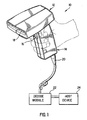
- reference numeral 10 generally identifies a hand-held, gun-shaped scanner head having a barrel 12 and a handle 14.
- the head need not be gun-shaped as any suitable configuration may be used, such as box-like.
- a manually-operable trigger 16 is situated below the barrel 12 on an upper, forwardly-facing part of the handle 14.
- a light source component typically, but not necessarily, a laser
- the light source emits a light beam along a transmission path which extends outwardly through a window 18 that faces indicia, e.g. bar code symbols, to be read.
- a photodetector component e.g. a photodiode, having a field of view, and operative for collecting reflected light returning through the window 14 along a return path from the symbol.
- a scanner component is mounted within the head 10, and is operative for scanning the symbol and/or the field of view of the photodetector.
- the scanner component includes at least one light reflector positioned in the transmission path and/or the return path.
- the reflector is driven by an electrically-operated drive to oscillate in alternate circumferential directions, preferably at the resonant frequency of the scanner component.
- the photodetector generates an electrical analog signal indicative of the variable intensity of the reflected light.
- This analog signal is converted into a digital signal by an analog-to-digital converter circuit.
- This digital signal is conducted, according to one embodiment, along an electrical cable 20 to a decode module 22 located exteriorly of the head 10.
- the decode module 22 decodes the digital signal into data descriptive of the symbol.
- An external host device 24, usually a computer, serves mainly as a data storage in which the data generated by the decode module 22 is stored for subsequent processing.
- each time a user wishes to have a symbol read the user aims the head at the symbol and pulls the trigger 16 to initiate reading of the symbol.
- the trigger 16 is an electrical switch that actuates the drive means.
- the symbol is repetitively scanned a plurality of times per second, e.g. 40 times per second. As soon as the symbol has been successfully decoded and read, the scanning action is automatically terminated, thereby enabling the scanner to be directed to the next symbol to be read in its respective turn.
- the head need not be a portable hand held type as fixedly mounted heads are also contemplated in this invention.
- the heads may have manually operated triggers or may be continuously operated by direct connection to an electrical source.
- the oscillations need only last a second or so, since the multiple oscillations, rather than time, increase the probability of getting a successful decode for a symbol, even a poorly printed one.
- the resonating reflector has a predetermined, predictable, known, generally uniform, angular speed for increased system reliability.
- one embodiment 30 of a high speed scanning arrangement of the present invention includes a flexible beam, e.g. a generally planar leaf spring 34.
- Leaf spring 34 has one end 36 fixedly mounted to an upright of an L-shaped bracket 38 which is anchored to a base support 40.
- Spring 34 has an opposite end 42 fixedly mounted to an upright of another L-shaped bracket 44 which is anchored to the base support 40.
- the uprights are oriented at 90° relative to each other.
- a central portion of the spring 34 is guided around a cylindrical clamping pin 46.
- the central portion of the spring 34 is clamped between the clamping pin 46 and a bearing surface of a V-block 48 by means of a set screw 50.
- the clamping pin 46 imparts a 90° bend to the leaf spring at the central portion.
- a scanner component e.g. a light reflector 52
- a rear support 54 which in turn, is fixedly secured to the V-block.
- the rear support 54 has a permanent magnet 56 mounted at one of its ends.
- An electromagnetic coil 58 is mounted adjacent the magnet 56 on an upright of another L-shaped bracket 60 which, in turn, is mounted on the base support 40.
- the coil 58 has a central passage 62 through which the magnet enters with clearance each time a momentary, periodic energizing pulse is applied to input leads 64.
- the frequency of the energizing pulse is preferably selected at the resonant frequency of where k equals the spring constant of leaf spring 34, and where I equals the moment of inertia of the magnet/reflector assembly suspended from the leaf spring.
- the assembly is oscillated about the axis 66.
- the spring is advantageously constituted of plastic or metal material. Non-metal materials would be more rugged.
- the leaf spring is bent. In the illustrated rest position, each arm of the leaf spring is generally planar. Upon being displaced, each arm of the leaf spring is bent, thereby storing energy therein.
- An L-shaped stop 68 mounted on the base support 40 is located behind the clamping pin 46 to prevent movement of the same past the stop.
- the pin 46 does not normally engage the stop; it is intended as a safety feature in the event that the arrangement is subjected to external shock forces.
- the flexible support near the center of rotation of the component provides an excellent shock absorber.
- the leaf spring 20 releases its stored energy, thereby displacing the magnet/reflector assembly back to and past the rest position.
- the entire assembly oscillates in a damped manner, until eventually coming to a halt in the rest position.
- Each arm of the leaf spring alternately assumes a concave and then a convex shape during such oscillation.
- Light directed from a source, e.g. a laser 70, onto the reflector 52 is swept in one direction in a scan across indicia to be read.
- a source e.g. a laser 70
- Another embodiment of the same configuration utilizes constant amplitude excitation, with continuous oscillation.
- the driving signal is a continuously applied AC signal that causes the magnet 56 to be cyclically drawn into the passage 62 and forced out of the passage 62.
- the spring 34 vibrates to oscillate the reflector 40 between scan end position.
- the holder means is a tuning fork which, as shown in Figure 3, comprises a stem 72 and a pair of arms 74, 76.
- a permanent magnet 78 is fixedly mounted on arm 74.
- a scanner component, e.g. a light reflector 80, is fixedly mounted on arm 76.
- the stem 72 rests on, and extends through, a base support 82 of an L-shaped frame which has an upright support 84 on which an electromagnetic coil 86 is mounted.
- a fastener 88 secures the stem 72 in an upright orientation to the frame for joint movement therewith. Electrical input leads 90 supply energizing signals to the coil 86.
- an energizing pulse is supplied to coil 86, the coil draws the magnet 78 into a passage 92 with clearance.
- the tuning fork is caused to vibrate, preferably at the resonance frequency which, as described above, is a function of the moment of inertia of the vibrating mass.
- the reflector 80 oscillates between the scan end positions A and B.
- a scan line (A1-B1) is formed which extends in one direction.
- an AC signal is continuously applied to the coil 86 to cyclically vibrate the arms 74 and 76 to osciallte the reflector 80 between scan end positions.
- the AC signal is tuned to vibrate the fork at the resonance frequency.
- the fork/frame assembly is mounted on an output shaft 94 of a motor 96 of the type described and claimed in U.S. Patent No. 4,496,831, the contents of which are incorporated herein by reference.
- Motor 96 is a torque motor operative for displacing output shaft 94 in an amount proportional to the electrical current supplied thereto. Motor 96 repetitively oscillates the output shaft 94 in alternate directions as indicated by the double-headed arrow 98.
- the output shaft 94 is coupled to the fork stem 72 by a coupler 100.
- a scan line (C-D) is formed which extends in a direction perpendicular to said one direction.
- the holder means includes a U-shaped spring means 110 having a pair of arms 112 and 114.
- a scanning component e.g. a light reflector or mirror 116 is fixedly mounted on arm 112 and a permanent magnet 118 is mounted on arm 114.
- An electromagnetic coil 120 is fixedly mounted to an upright support 122 that is secured to a base 124. Electrical input leads 126 supply the energizing signal to the coil 120.
- the arm 114 and magnet 118 are secured to a generally planar spring means 128 that is mounted to the base 124.
- the planar spring 128 may be made of any suitable flexible material, such as, a leaf spring, a flexible metal foil, a flat bar or a Bendix flex-pivot-type spring.
- the mirror mass which is equal to the magnet mass, can be in certain cases much higher than the equivalent mass of the U-shaped spring.
- a raster-type scan pattern In certain applications, it is desirable to scan indicia with a raster-type scan pattern.
- a raster-type scan pattern a series of substantially horizontal and substantially parallel scan lines are produced from an upper horizontal scan line, proceeding downward with a multiplicity of intermediate horizontal scan lines, to a lower horizontal scan line in order to uniformly cover the desired scan area.
- the U-shaped spring 110 and the planar spring 128 are arranged to vibrate in planes orthogonal to each other. As shown in Figure 4, the arms of the U-shaped spring will vibrate in the x-z plane and the planar spring 228 will vibrate in the x-y plane.
- the component 116 is mounted for angular oscillating movement, in first and second alternate circumferential directions, between first and second pairs of scan end positions.
- the U-shaped spring 110 will vibrate at a high range of frequencies, typically about 200-800 Hz, while the planar spring 128 will vibrate at a low range of frequencies, typically about 5-100 Hz.
- the amplitude of vibration necessary to scan the symbol will depend on the size of the symbol and will typically be at least 10-30° optical.
- a raster-type scan pattern is automatically obtained by driving the coil 120 with a signal that is a superposition of two driving signals, one being within the high frequency range and the other being within the low frequency range.
- a 500 Hz square wave signal may be utilized to oscillate component 116 in the x direction and a 10 Hz sine wave signal may be utilized to oscillate to component 116 in the y direction.
- the combination of the fast oscillations of the component in the x direction and the slow oscillations of the component in the y direction results in a raster-type scan pattern over the indicia.
- the high frequency signal is frequency tuned to the resonant frequency of the U-shaped spring 110.
- the planar spring 128 will be driven below its resonant frequency.
- the coil cyclically draws the magnet 118 into a passage 130 and propels the magnet 118 out of the passage 130.
- the high frequency component of the driving signal causes the U-shaped spring to vibrate, preferably at the resonant frequency, causing the component 116 to be angularly oscillated between scan end positions X1, X2.
- the low frequency component of the driving signal causes the planar spring 128 to angularly vibrate towards and away from the support 122 about pivot line 123. During this low frequency vibration, the spring 128 and the fork 110 move as a unit. The vibration of planar spring 128 imparts an angular oscillating movement to the component 116 between scan end positions Y1, Y2.
- Figure 4 is advantageously provided of a very simple construction which utilizes only one driver (one coil and one magnet) for oscillating movement in two directions to form a raster-type scan pattern. There are no shafts or bearings but only flexible metals are used which result in much longer life.
- the U-shaped spring 110 with asymmetrically dimensioned arms.
- arm 112 is shorter than arm 114 by ratio of at least 2:1.
- An asymmetrically dimensioned U-shaped spring will result in a longer x direction scan line in the raster-type pattern.
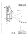
- FIG. 5 An example of asymmetrically dimensioned U-shaped spring is shown in Figure 5 in which the tuning fork 121 is constructed having a small dimensioned arm 123 and a large dimensioned arm 125 which results in the nodal point 127 of the spring being positioned on arm 125 rather than at the bottom of the U as with a symmetrically dimensioned spring.
- the component 129 is mounted to arm 123 and the actuator comprises an electromagnetic coil 131 having a passage 133 through which magnet 135 passes with clearance.
- the U-shaped spring 121 is secured to a support 137 by a planar spring 139.
- the spring 139 is secured to base section 141 and the coil 131 is mounted to wall section 143.
- Leads 145 are provided to apply the driving signal to the coil 131 to effect angular movement of the component 129.
- the asymmetrically dimensioned U-shaped spring 121 provides an increased angular amplitude of the scan resulting from light directed from a laser 147 and reflected from component 129.
- the asymmetrically dimensioned U-shaped spring provides a higher durability against metal fatigue and cracking since the nodal point is not at a curved portion of the spring.
- a section 149 of spring 139 that is substantially parallel to wall 143 and section 151 angled away from wall 143 while at rest.
- the angled section 151 results in a further increase in the angular amplitude of scan oscillations (as much as 200% higher) over a symmetrically dimensioned U-shaped spring.
- Another benefit is less vibration being transferred to the base since the U-shaped spring is held only at the magnet end and angular movement of the magnet can be four times lower than that of the scanning component.
- FIG. 5 is an elevated view showing the U-shaped spring 121 and the planar spring 139 both positioned for vibration in the x-y plane resulting in a single scan line directed along the y direction. If the U-shaped and planar springs are positioned in orthogonal planes as in Figure 4, and an appropriate superimposed high and low frequency driving signal is applied to the coil, a raster-type scan pattern will be provided with an increased x direction angular amplitude.
- the y direction scan vibratory means may also include a generally S shaped planar leaf spring 134 having one arm 136 secured to planar spring 128 and another arm 138 to which is mounted a balance mass 140.
- An additional generally upright planar spring 142 secures an intermediate portion of the planar spring 134 to the base 124.
- the S-shaped spring is useful to provide additional support that may be necessary for very large area reflectors.
- a single planar spring 150 provides the oscillatory movement in two orthogonal axes for a raster-type scan pattern.
- the spring 150 is mounted to base 152 and has mounted on it the light reflector 154.
- a magnet 156 is mounted to the spring 150 on the opposite side as that of the reflector 154.
- An electromagnetic coil 158 having a passage 160 is mounted adjacent the permanent magnet 156 on an upright bracket member 162 that is in turn mounted to base 152.
- an axis 164 is formed by the magnet 156 and coil 158 which runs through the center of spring 150.
- the light reflector 154 is mounted to the planar spring 150 with its center of gravity 166 offset from axis 164.
- the raster-type scan pattern is effected by applying a superimposed high and low frequency AC signal to leads 168.
- the magnet 156 In response to the low frequency component (about 20-30 Hz) of the superimposed driving signal, the magnet 156 enters and exits the passage 160 in a cyclical manner which causes the spring 150 to angularly vibrate about pivot line 151. The vibration causes the component 154 to angularly oscillate in the x-y plane which results in a slow y direction scan.
- the spring 150 is torsionally bent about its axis 164 due to the alignment of the center of gravity of the reflector 154.
- the offset center of gravity of reflector 154 acts to provide a restoring force to the spring 150 causing torsional vibration of spring 150.
- the spring 150 is constructed such that when the coil is energized, the component 154 will oscillate angularly at the higher frequency in the x-z plane to provide a fast x directed scan.
- the indicia is scanned in a two axis raster-type scan pattern, consisting of a series of x directed scan lines 153 vertically spaced in the y direction.
- the difference in the high and low frequency component of the driving signal produces a large x-directed angular amplitude and a small y-directed angular amplitude resulting in a raster-type scan pattern being developed.
- the angular amplitude of the x direction scan may be as high as about 90° optical while the angular amplitude of the y direction scan may be up to about 5° optical.
- the movement of the spring 139 towards the coil 131 and away from the coil 131 causes the U-shaped spring 121 to vibrate in the x-z plane which imparts an angular oscillatory movement to the component 129 for effecting an x direction scan.
- the superimposed driving signal preferably comprised of a pair of sine waves having a frequency ratio in the range of 1.05:1 to 5:1, to leads 145, spring 139 torsionally vibrates at the lower frequency and the U-shaped spring 121 simultaneously vibrates at the higher frequency in such a manner that light will be reflected from the component 129 in a Lissajous scan pattern over the indicia.
- the Lissajous pattern is provided by the path of the light beam being oscillated in the x and y orthogonal directions in simple harmonic motions at a predetermined ratio of frequencies.
- an omnidirectional scan pattern is produced.
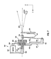
- Figure 7 shows another technique for producing an omnidirectional scan pattern namely, rotating the entire holder means about an axis.
- the arrangement shown in Figure 7 is similar to that of Figure 5 and like reference numerals are used to identify like parts and a description thereof is not repeated here for the sake of brevity.
- means 180 is provided to rotate the arrangement about an axis 182.
- the means 180 shown in Figure 7 is illustrative only as any suitable means for rotating the scanning arrangement about an axis may be employed to effect an omnidirectional scan pattern.
- the means 180 includes a motor 182 having a shaft 184 for driving a transmission belt 186.
- Belt 186 is coupled to a shaft (not shown) connected to the support 137 for rotating the support 137 about ball bearing 188 which is attached to support beam 190.
- the rotation of a single axis direction scan arrangement will produce an omnidirectional scan pattern in the form of a Rosette.
- the rotation of a two-axis scan arrangement will produce various other omnidirectional patterns depending on the type of two-axis arrangement rotated.
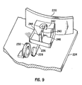
- a magnetically activated return means is provided for effecting a spring like restoring force to oscillate the component between scan end positions.
- a scanning component 220 is mounted for rotational movement about shaft 222 which is rotationally secured to base 224.
- a support bracket or lever 226 extends from the component 220 and has mounted on the end thereof a permanent magnet 228.
- An electromagnetic coil 230 is mounted to the base 224 in operational proximity to the permanent magnet 228.
- a magnetic member 232 is mounted immediately below the permanent magnet 228 on a pem-nut 234.
- the permanent magnet 228 is a disk or rectangular shaped member in which faces 236 and 238 (not shown) are magnetized to be of opposite magnetic poles.
- face 236 may be the north pole and face 238 may be the south pole, or vice versa.
- the magnetic member 232 is made magnetic permeable material such as a soft iron core.
- the coil 230 is energized by an AC voltage and the alternating positive and negative current will cause the permanent magnet to alternately be attracted to the coil and repelled from the coil. This will impart an oscillatory angular movement to the scanning mirror 220 between scan end positions. During the oscillatory movement of the component, the permanent magnet 228 will pass over the soft iron core 232 in a back and forth motion.
- the coil 230 is de-energized, the magnetic interaction between the magnetic fields of the permanent magnet 228 and soft iron core 232 forces the magnet 228 and, accordingly, the entire moving assembly to align itself with a line of a magnetic equilibrium of the soft core 232, which crosses its center.
- the permanent magnet 228 When the coil 230 is energized, depending on the phase of the AC current, the permanent magnet 228 is either attracted to or repelled from the coil 230 thus magnetizing the core 232 with the polarity opposite to the polarity of the side of the permanent magnet 228 facing the core 232. Since two unlike poles are attracted to each other, this attraction creates a restoring force equivalent to a spring action to cause the component to move towards the equilibrium position. Extreme left and extreme right scan end positions are determined by the relationship between magnitude and phase of the AC current through the coil 230 and the geometry and material of the core 232 which, in turn, determine the value of the restoring torque.
- the above described mechanism causes the moving assembly to come to a halt in the rest (“equilibrium") position.
- a second electromagnetic coil (not shown) may be provided around core 232 such that member 232 will form the core of the second coil.
- a DC current energizing the second coil will increase the restoring force of the soft iron core.
- member 232 may be a permanent magnet. If the magnet 228 is mounted with its north pole facing away from the coil, magnet 232 would need to have its south pole facing upward. Magnet 232 must be oppositely arranged if the south pole of magnet 228 is facing away from the coil.
- a restoring force is provided by an elastic member 240.
- the elastic member 240 may be any suitable material having elastic properties such as rubber, a room temperature vulcanizer (RTV), or any similar plastic.
- the elastic member 240 is secured to the component 220 by bracket 242, and is also secured to the support 224 by bracket 244.
- Frame member 246 connects the component 220 to the shaft support 226.
- the oscillatory movements of component 220 generated by the AC current applied to coil 230 causes RTV 242 to be stretched to its limit to define the scan end positions and upon deactivation of the coil 230, RTV 240 acts to restore the component 220 to its rest position.
- the invention may be summarized as follows:
Abstract
Description
- This invention generally relates to a scanning arrangement in a scanner operative for repetitively scanning indicia having parts of different light reflectivity, for example, bar code symbols, and, more particularly, to operating such a scanning arrangement at high speeds in single or multi-axis scan patterns.
- Various optical readers and optical scanners have been developed heretofore to optically read bar code symbols applied to objects in order to identify the object by optically reading the symbol thereon. The bar code symbol itself is a coded pattern comprised of a series of bars of various widths and spaced apart from one another to bound spaces of various widths, the bars and spaces having different light reflecting properties. The readers and scanners electro-optically decoded the coded patterns to multiple digit representations descriptive of the objects. Scanners of this general type have been disclosed, for example, in U.S. Patent Nos. 4,251,798; 4,360,798; 4,369,361; 4,387,297; 4,593,186; 4,496,831; 4,409,470; 4,808,804; 4,816,661; 4,816,660; and 4,871,904, all of said patents having been assigned to the same assignee as the instant invention and being hereby incorporated herein by reference.
- As disclosed in the above-identified patents and applications, a particularly advantageous embodiment of such a scanner resided, inter alia, in emitting a light beam, preferably a laser beam, emitted from a light source, preferably a gas laser or a laser diode, and in directing the laser beam to a symbol to be read. En route to the symbol, the laser beam was directed to, and reflected off, a light reflector of a scanning component. The scanning component moved the reflector in a cyclical fashion and caused the laser beam to repetitively scan the symbol. The symbol reflected the laser beam incident thereon. A portion of the incident light reflected off the symbol was collected and detected by a detector component, e.g. a photodiode, of the scanner. The photodiode had a field of view, and the detected light over the field of view was decoded by electrical decode circuitry into data descriptive of the symbol for subsequent processing. The cyclically movable reflector swept the laser beam across the symbol and/or swept the field of view during scanning.
- U.S. Patent Nos. 4,387,297 and 4,496,831 disclose a high-speed scanning component including an electric motor operative for reciprocatingly oscillating a reflector in opposite circumferential directions relative to an output shaft of the motor. Electrical power is continuously applied to the motor during scanning. The light beam which impinges on the light reflector is rapidly swept across a symbol to be scanned in a predetermined cyclical manner. The scanning component comprises at least one scan means for sweeping the symbol along a predetermined direction (X-axis) lengthwise thereof. The scanning component may also comprise another scan means for sweeping the symbol along a transverse direction (Y-axis) which is substantially orthogonal to the predetermined direction, to thereby generate a raster-type scan pattern over the symbol. In addition to a single scan line and the raster-type pattern, other types of scan patterns are also possible, such as, x-shaped, Lissajous, curvilinear (see U.S. Patent 4,871,904), etc. For example, if the X and Y axis scanning motors are both driven such that the light reflectors are driven at a sinusoidally-varying rate of speed, then the scan pattern at the reference plane will be a Lissajous-type pattern for omni-directional scanning of the symbols. The use of two separate scanning motors and control means to produce the multi-axis and omni-directional scanning pattern increases material and labor costs as well as the amount of electrical power needed to operate the scanner. In addition, the relatively complicated motor shaft and bearing arrangements of the scanning components may result in a useful life that is inadequate for some applications. Furthermore, the scanning components disclosed in U.S. Patents 4,387,297 and 4,496,831 are designed for miniature light reflectors and are not well suited for large scale reflectors.
- It is a general object of this invention to advance the state of the art of scanners for reading indicia of different light reflectivity, particularly laser scanners for reading bar code symbols.
- An additional object of this invention is to provide novel high-speed scanning elements and novel scanning methods of operation.
- Yet another object of this invention is to conveniently generate single line, multi-line or omni-directional scan patterns with the same scanning elements.
- A further object of this invention is to provide a scanning arrangement having an increased scan line amplitude.
- It is another object of this invention to minimize the number of elements comprising the scanning component.
- Another object of this invention is to increase the working lifetime of the scanning components.
- In keeping with these objects, and others which will become apparent hereinafter, this invention resides, briefly stated, in an arrangement for, and a method of, scanning indicia having parts of different light reflectivity by directing light toward the indicia and by collecting reflected light returning from the indicia. This invention comprises a scanner component supported by holder means for angular oscillating movement in a single scan direction between a pair of scan end positions or alternatively, in first and second scan directions between first and second pairs of scan end positions. According to this invention, read-start means are provided for moving the component between the scan end positions.
- In one feature, the component is simultaneously angularly oscillated between the first and second pair of scan end positions for directing light along the first and second scan directions to thereby effect a multi-directional scan pattern over the indicia.
- In one embodiment, the holder means is a planar leaf spring having opposite ends anchored and the scanner component mounted on a bent central portion of the spring. The read start means is comprised of a permanent magnet mounted to the holder and an electromagnetic coil for displacing the magnet in response to a driving signal. By energizing the nearby coil, the magnet and, in turn, the scanner component are oscillated, preferably at the resonant frequency of the component/magnet assembly.
- In another embodiment, the holder means is a tuning fork having a permanent magnet fixedly mounted on one arm of the fork and the scanner component fixedly mounted on the other arm. The read-start means is comprised of an electromagnetic coil for displacing the magnet and, in turn, for oscillating the scanner component in a scan which extends in the first direction over the indicia. The stem of the fork may also be oscillated by a second read-start means comprised of a stepper motor to scan the indicia in the second direction generally perpendicular to the first direction to effect two-dimensional scanning.
- In a further embodiment of the present invention, a two-dimensional scan pattern over the indicia is advantageously effected by a holder means that is constructed for mounting the component for angular oscillating movement along first and second axes in response to a single read-start means.
- In one embodiment, the first and second vibratory means are mounted in orthogonal planes relative to each other and cooperate for angular oscillatory movement of the component about the first and second axes. The first vibratory means is constructed to vibrate at a high range of frequencies and the second vibratory means is constructed to vibrate at a low range of frequencies in response to a driving signal. The driving signal is comprised of a superposition of a first A.C. signal within the high frequency range and a second A.C. signal within the low frequency range to thereby effect a two-axis raster-type scan pattern. In this embodiment, the first vibratory means is a generally U-shaped leaf spring having a permanent magnet mounted on one arm and the scanner component mounted on the other arm, and the second vibratory means is a generally planar leaf spring having one end secured to the arm of the U-shaped spring having the magnet and the other end secured to a base forming a vibration pivot line. The superimposed driving signal is supplied to an electromagnetic coil for displacing the magnet and, in turn, for oscillating the scanner component in two orthogonal scan directions over the indicia to form the raster pattern. In an alternative embodiment, the second vibratory means includes a generally S-shaped leaf spring secured to the planar leaf spring.
- In another embodiment of a two-axis raster-type scan arrangement, the holder means includes a generally planar leaf spring having one end secured to a base to form a vibration pivot line and the component mounted on the free end of the spring. The center of mass of the component is offset from the axis formed by an electromagnetic coil and a magnet mounted to the leaf spring. The offset center of mass of the component provides a restoring force to torsionally vibrate the planar spring along the first scan direction at a high range of frequencies and the leaf spring vibrates about the pivot line along the second scan direction at a low range of frequencies to effect the raster-type scan pattern over the indicia in response to a superimposed high and low frequency driving signal.
- In another feature of the invention, an omni-directional scan pattern over the indicia is provided. First and second vibratory means are arranged such that in response to a superposition of driving signals having a frequency ratio relative to each other of 5:1 or less, a Lissajous scan pattern is effected. The first vibratory means is a generally U-shaped leaf spring in which one arm is mounted to the component and the other arm is mounted to the second vibratory means which includes a generally planar leaf spring secured to the base forming a pivot line. The leaf spring includes a permanent magnet mounted on one side that cooperates with an electromagnetic coil. Mounted on the other side of the leaf spring is the U-shaped spring with the component. The direction of vibration of the leaf spring about the pivot line and the direction of vibration of the U-shaped spring are the same. In this embodiment, the weight of the U-shaped spring and component results in a torsional vibration of the planar spring for oscillating the component along one scan direction and the vibration of the leaf spring about the pivot point results in the component being oscillated along a second scan direction. The simultaneous vibration in the two axes generated by the 5 to 1 or less frequency superimposed driving signal provides the Lissajous scan pattern.
- In an improved construction of the U-shaped spring comprising the holder means in the various embodiments described above, the angular amplitude of the scan line produced by the U-shaped spring is increased by providing the spring with asymmetrically dimensioned arms. The asymmetrically dimensioned construction may be implemented to increase the angular amplitude in either a one or two axis scan arrangement.
- In a further feature of the present invention, various improvements in the means for providing the necessary restoring force to repeatably oscillate the compound between scan end positions is provided.
- In one embodiment, the read-start means includes a magnetic return means that provides a spring-like restoring force for oscillating the component between scan end positions. The magnetic return means includes a stationary permeable magnetic core positioned adjacent a movable permanent magnet at an equilibrium position. The magnet is operatively connected to the component for moving the component between scan end positions. The permanent magnet is alternately attracted to and repelled from an electromagnetic coil when the coil is energized by an alternating current driving signal. During actuation of the coil, the magnet passes back and forth over the core which alternately magnetizes the core with a polarity opposite to the side of the magnet facing the core thereby creating a magnetic restoring force causing the magnet to return to the equilibrium position over the center of the core. In a further embodiment, a second electromagnetic coil may be provided in operative arrangement with the core to strengthen the magnetic field of the core. Alternatively, the core may be formed of a permanent magnet material.
- In another feature of the invention, the restoring means may be in the form of an elastic member, such as a room temperature vulcanizer, attached to the component that acts like a spring to restore the component to the rest position.
- The novel features which are considered as characteristic of the invention are set forth in particular in the appended claims. The invention itself, however, both as to its construction and its method of operation, together with additional objects and advantages thereof, will be best understood from the following description of specific embodiments when read in connection with the accompanying drawings.
-
- Figure 1 is a front perspective view of hand-held head employed in a scanner;
- Figure 2 is a top plan view of a further embodiment of a scanning arrangement according to this invention;
- Figure 3 is a side view of another embodiment of a scanning arrangement according to this invention;
- Figure 4 is a perspective view of yet another embodiment of a scanning arrangement according to this invention;
- Figure 5 is a cross-sectional view of a further embodiment of the scanning arrangement according to this invention;
- Figures 6a and 6b are side and front views of an additional embodiment of the scanning arrangement according to this invention;
- Figure 7 is a cross-sectional view of yet another embodiment of a scanning arrangement according to this invention;
- Figure 8 is a perspective view of an additional embodiment of the scanning arrangement according to this invention; and
- Figure 9 is a perspective view of a further embodiment of the scanning arrangement according to this invention.
- Referring now to the drawings, as shown in Figure 1,
reference numeral 10 generally identifies a hand-held, gun-shaped scanner head having abarrel 12 and ahandle 14. The head need not be gun-shaped as any suitable configuration may be used, such as box-like. A manually-operable trigger 16 is situated below thebarrel 12 on an upper, forwardly-facing part of thehandle 14. As known from the above-identified patents and applications incorporated by reference herein, a light source component, typically, but not necessarily, a laser, is mounted inside thehead 10. The light source emits a light beam along a transmission path which extends outwardly through awindow 18 that faces indicia, e.g. bar code symbols, to be read. Also mounted within the head is a photodetector component, e.g. a photodiode, having a field of view, and operative for collecting reflected light returning through thewindow 14 along a return path from the symbol. - A scanner component is mounted within the
head 10, and is operative for scanning the symbol and/or the field of view of the photodetector. The scanner component includes at least one light reflector positioned in the transmission path and/or the return path. The reflector is driven by an electrically-operated drive to oscillate in alternate circumferential directions, preferably at the resonant frequency of the scanner component. - The photodetector generates an electrical analog signal indicative of the variable intensity of the reflected light. This analog signal is converted into a digital signal by an analog-to-digital converter circuit. This digital signal is conducted, according to one embodiment, along an
electrical cable 20 to adecode module 22 located exteriorly of thehead 10. Thedecode module 22 decodes the digital signal into data descriptive of the symbol. Anexternal host device 24, usually a computer, serves mainly as a data storage in which the data generated by thedecode module 22 is stored for subsequent processing. - In operation, each time a user wishes to have a symbol read, the user aims the head at the symbol and pulls the
trigger 16 to initiate reading of the symbol. Thetrigger 16 is an electrical switch that actuates the drive means. The symbol is repetitively scanned a plurality of times per second, e.g. 40 times per second. As soon as the symbol has been successfully decoded and read, the scanning action is automatically terminated, thereby enabling the scanner to be directed to the next symbol to be read in its respective turn. - In addition, the head need not be a portable hand held type as fixedly mounted heads are also contemplated in this invention. Furthermore, the heads may have manually operated triggers or may be continuously operated by direct connection to an electrical source.
- The oscillations need only last a second or so, since the multiple oscillations, rather than time, increase the probability of getting a successful decode for a symbol, even a poorly printed one. The resonating reflector has a predetermined, predictable, known, generally uniform, angular speed for increased system reliability.
- As shown in Figure 2, one
embodiment 30 of a high speed scanning arrangement of the present invention, includes a flexible beam, e.g. a generallyplanar leaf spring 34.Leaf spring 34 has oneend 36 fixedly mounted to an upright of an L-shapedbracket 38 which is anchored to abase support 40.Spring 34 has anopposite end 42 fixedly mounted to an upright of another L-shapedbracket 44 which is anchored to thebase support 40. The uprights are oriented at 90° relative to each other. A central portion of thespring 34 is guided around acylindrical clamping pin 46. The central portion of thespring 34 is clamped between the clampingpin 46 and a bearing surface of a V-block 48 by means of aset screw 50. The clampingpin 46 imparts a 90° bend to the leaf spring at the central portion. - A scanner component, e.g. a
light reflector 52, is fixedly mounted to arear support 54 which in turn, is fixedly secured to the V-block. Therear support 54 has apermanent magnet 56 mounted at one of its ends. Anelectromagnetic coil 58 is mounted adjacent themagnet 56 on an upright of another L-shapedbracket 60 which, in turn, is mounted on thebase support 40. Thecoil 58 has acentral passage 62 through which the magnet enters with clearance each time a momentary, periodic energizing pulse is applied to input leads 64. The frequency of the energizing pulse is preferably selected at the resonant frequency of
where k equals the spring constant ofleaf spring 34, and where I equals the moment of inertia of the magnet/reflector assembly suspended from the leaf spring. The assembly is oscillated about theaxis 66. The spring is advantageously constituted of plastic or metal material. Non-metal materials would be more rugged. - In operation, each time the energizing pulse is applied to the
coil 58, themagnet 56 is drawn into thepassage 62, thereby pulling thereflector 52, therear support 54, the V-block 48, the clampingpin 46, theset screw 50 therealong. At the same time, the leaf spring is bent. In the illustrated rest position, each arm of the leaf spring is generally planar. Upon being displaced, each arm of the leaf spring is bent, thereby storing energy therein. An L-shapedstop 68 mounted on thebase support 40 is located behind the clampingpin 46 to prevent movement of the same past the stop. Thepin 46 does not normally engage the stop; it is intended as a safety feature in the event that the arrangement is subjected to external shock forces. The flexible support near the center of rotation of the component provides an excellent shock absorber. - Once bent, the
leaf spring 20 releases its stored energy, thereby displacing the magnet/reflector assembly back to and past the rest position. The entire assembly oscillates in a damped manner, until eventually coming to a halt in the rest position. Each arm of the leaf spring alternately assumes a concave and then a convex shape during such oscillation. Light directed from a source, e.g. alaser 70, onto thereflector 52 is swept in one direction in a scan across indicia to be read. Another embodiment of the same configuration utilizes constant amplitude excitation, with continuous oscillation. In this embodiment, the driving signal is a continuously applied AC signal that causes themagnet 56 to be cyclically drawn into thepassage 62 and forced out of thepassage 62. Thespring 34 vibrates to oscillate thereflector 40 between scan end position. - By providing a well defined center of rotation at
axis 66 that is close to the scan component, image translation is minimized. In addition, in this configuration the scan pattern stays centered regardless of the scan position. - In still another variant, the holder means is a tuning fork which, as shown in Figure 3, comprises a
stem 72 and a pair ofarms permanent magnet 78 is fixedly mounted onarm 74. A scanner component, e.g. alight reflector 80, is fixedly mounted onarm 76. Thestem 72 rests on, and extends through, a base support 82 of an L-shaped frame which has anupright support 84 on which anelectromagnetic coil 86 is mounted. Afastener 88 secures thestem 72 in an upright orientation to the frame for joint movement therewith. Electrical input leads 90 supply energizing signals to thecoil 86. - In operational embodiment, whenever an energizing pulse is supplied to
coil 86, the coil draws themagnet 78 into apassage 92 with clearance. When the pulse ends, the tuning fork is caused to vibrate, preferably at the resonance frequency which, as described above, is a function of the moment of inertia of the vibrating mass. Thereflector 80 oscillates between the scan end positions A and B. When light emitted from a source,e.g. laser 92, is directed at thereflector 80, a scan line (A₁-B₁) is formed which extends in one direction. In a second operational embodiment, an AC signal is continuously applied to thecoil 86 to cyclically vibrate thearms reflector 80 between scan end positions. Preferably, the AC signal is tuned to vibrate the fork at the resonance frequency. - In an improved construction, the fork/frame assembly is mounted on an
output shaft 94 of amotor 96 of the type described and claimed in U.S. Patent No. 4,496,831, the contents of which are incorporated herein by reference.Motor 96 is a torque motor operative for displacingoutput shaft 94 in an amount proportional to the electrical current supplied thereto.Motor 96 repetitively oscillates theoutput shaft 94 in alternate directions as indicated by the double-headed arrow 98. Theoutput shaft 94 is coupled to the fork stem 72 by acoupler 100. - As shown in Figure 3, the opposite end of the
output shaft 94 is restrained by a centeringtorsion spring 102. As theoutput shaft 94 is oscillated, the centeringtorsion spring 102 operates to return theoutput shaft 94 to the rest position. A scan line (C-D) is formed which extends in a direction perpendicular to said one direction. - Another embodiment of a two axis scan pattern arrangement is shown in Figure 4, in which the holder means includes a U-shaped spring means 110 having a pair of
arms mirror 116 is fixedly mounted onarm 112 and apermanent magnet 118 is mounted onarm 114. Anelectromagnetic coil 120 is fixedly mounted to anupright support 122 that is secured to abase 124. Electrical input leads 126 supply the energizing signal to thecoil 120. Thearm 114 andmagnet 118 are secured to a generally planar spring means 128 that is mounted to thebase 124. Theplanar spring 128 may be made of any suitable flexible material, such as, a leaf spring, a flexible metal foil, a flat bar or a Bendix flex-pivot-type spring. The mirror mass, which is equal to the magnet mass, can be in certain cases much higher than the equivalent mass of the U-shaped spring. - In certain applications, it is desirable to scan indicia with a raster-type scan pattern. In a raster-type scan pattern, a series of substantially horizontal and substantially parallel scan lines are produced from an upper horizontal scan line, proceeding downward with a multiplicity of intermediate horizontal scan lines, to a lower horizontal scan line in order to uniformly cover the desired scan area. In order to obtain a raster-type scan pattern, the
U-shaped spring 110 and theplanar spring 128 are arranged to vibrate in planes orthogonal to each other. As shown in Figure 4, the arms of the U-shaped spring will vibrate in the x-z plane and theplanar spring 228 will vibrate in the x-y plane. By this arrangement of the holder means, thecomponent 116 is mounted for angular oscillating movement, in first and second alternate circumferential directions, between first and second pairs of scan end positions. In addition, due to their respective shapes and positioning, theU-shaped spring 110 will vibrate at a high range of frequencies, typically about 200-800 Hz, while theplanar spring 128 will vibrate at a low range of frequencies, typically about 5-100 Hz. The amplitude of vibration necessary to scan the symbol will depend on the size of the symbol and will typically be at least 10-30° optical. - A raster-type scan pattern is automatically obtained by driving the
coil 120 with a signal that is a superposition of two driving signals, one being within the high frequency range and the other being within the low frequency range. For example, a 500 Hz square wave signal may be utilized to oscillatecomponent 116 in the x direction and a 10 Hz sine wave signal may be utilized to oscillate tocomponent 116 in the y direction. The combination of the fast oscillations of the component in the x direction and the slow oscillations of the component in the y direction results in a raster-type scan pattern over the indicia. Preferably, the high frequency signal is frequency tuned to the resonant frequency of theU-shaped spring 110. Typically, theplanar spring 128 will be driven below its resonant frequency. - In this arrangement, whenever the superimposed AC driving signal is supplied to
coil 120, the coil cyclically draws themagnet 118 into apassage 130 and propels themagnet 118 out of thepassage 130. The high frequency component of the driving signal causes the U-shaped spring to vibrate, preferably at the resonant frequency, causing thecomponent 116 to be angularly oscillated between scan end positions X1, X2. The low frequency component of the driving signal causes theplanar spring 128 to angularly vibrate towards and away from thesupport 122 aboutpivot line 123. During this low frequency vibration, thespring 128 and thefork 110 move as a unit. The vibration ofplanar spring 128 imparts an angular oscillating movement to thecomponent 116 between scan end positions Y1, Y2. When light emitted fromlaser 132 is directed atreflector 116 while theU-shaped spring 110 and theplanar spring 128 are vibrating simultaneously at the high and low frequencies, respectively, a series of substantially horizontal scan lines 111 in the x direction are produced that are displaced in the y direction thereby forming a raster-type scan pattern. - The arrangement of Figure 4 is advantageously provided of a very simple construction which utilizes only one driver (one coil and one magnet) for oscillating movement in two directions to form a raster-type scan pattern. There are no shafts or bearings but only flexible metals are used which result in much longer life.
- In certain applications, it is desirable to increase the angular amplitude by the scan line produced by the holder. Such an increase in angular amplitude may be attained by constructing the
U-shaped spring 110 with asymmetrically dimensioned arms. In this embodiment,arm 112 is shorter thanarm 114 by ratio of at least 2:1. An asymmetrically dimensioned U-shaped spring will result in a longer x direction scan line in the raster-type pattern. - An example of asymmetrically dimensioned U-shaped spring is shown in Figure 5 in which the
tuning fork 121 is constructed having a small dimensionedarm 123 and a large dimensionedarm 125 which results in thenodal point 127 of the spring being positioned onarm 125 rather than at the bottom of the U as with a symmetrically dimensioned spring. As shown in Figure 5, thecomponent 129 is mounted toarm 123 and the actuator comprises anelectromagnetic coil 131 having apassage 133 through whichmagnet 135 passes with clearance. TheU-shaped spring 121 is secured to asupport 137 by aplanar spring 139. Thespring 139 is secured tobase section 141 and thecoil 131 is mounted towall section 143.Leads 145 are provided to apply the driving signal to thecoil 131 to effect angular movement of thecomponent 129. The asymmetrically dimensionedU-shaped spring 121 provides an increased angular amplitude of the scan resulting from light directed from alaser 147 and reflected fromcomponent 129. - In addition to increasing the angular amplitude, which can be as much as a 100% increase over a symmetrically dimensioned spring, the asymmetrically dimensioned U-shaped spring provides a higher durability against metal fatigue and cracking since the nodal point is not at a curved portion of the spring. Also shown in Figure 5, is a
section 149 ofspring 139 that is substantially parallel towall 143 andsection 151 angled away fromwall 143 while at rest. Theangled section 151 results in a further increase in the angular amplitude of scan oscillations (as much as 200% higher) over a symmetrically dimensioned U-shaped spring. Another benefit is less vibration being transferred to the base since the U-shaped spring is held only at the magnet end and angular movement of the magnet can be four times lower than that of the scanning component. - The arrangement of Figure 5 is an elevated view showing the
U-shaped spring 121 and theplanar spring 139 both positioned for vibration in the x-y plane resulting in a single scan line directed along the y direction. If the U-shaped and planar springs are positioned in orthogonal planes as in Figure 4, and an appropriate superimposed high and low frequency driving signal is applied to the coil, a raster-type scan pattern will be provided with an increased x direction angular amplitude. - Referring back to Figure 4, in an alternative embodiment, the y direction scan vibratory means may also include a generally S shaped
planar leaf spring 134 having onearm 136 secured toplanar spring 128 and anotherarm 138 to which is mounted abalance mass 140. An additional generally uprightplanar spring 142 secures an intermediate portion of theplanar spring 134 to thebase 124. The S-shaped spring is useful to provide additional support that may be necessary for very large area reflectors. - In another embodiment shown in Figures 6a and 6b, a single
planar spring 150 provides the oscillatory movement in two orthogonal axes for a raster-type scan pattern. Thespring 150 is mounted tobase 152 and has mounted on it thelight reflector 154. Amagnet 156 is mounted to thespring 150 on the opposite side as that of thereflector 154. Anelectromagnetic coil 158 having apassage 160 is mounted adjacent thepermanent magnet 156 on anupright bracket member 162 that is in turn mounted tobase 152. As shown in Figure 6b, anaxis 164 is formed by themagnet 156 andcoil 158 which runs through the center ofspring 150. Thelight reflector 154 is mounted to theplanar spring 150 with its center ofgravity 166 offset fromaxis 164. - The raster-type scan pattern is effected by applying a superimposed high and low frequency AC signal to leads 168. In response to the low frequency component (about 20-30 Hz) of the superimposed driving signal, the
magnet 156 enters and exits thepassage 160 in a cyclical manner which causes thespring 150 to angularly vibrate aboutpivot line 151. The vibration causes thecomponent 154 to angularly oscillate in the x-y plane which results in a slow y direction scan. In response to the medium-high frequency component (about 50-200 Hz) of the superimposed AC driving signal, thespring 150 is torsionally bent about itsaxis 164 due to the alignment of the center of gravity of thereflector 154. The offset center of gravity ofreflector 154 acts to provide a restoring force to thespring 150 causing torsional vibration ofspring 150. Thespring 150 is constructed such that when the coil is energized, thecomponent 154 will oscillate angularly at the higher frequency in the x-z plane to provide a fast x directed scan. When light emitted fromlaser 170 is reflected off of themirror 154, while thecoil 158 is energized, the indicia is scanned in a two axis raster-type scan pattern, consisting of a series of x directed scan lines 153 vertically spaced in the y direction. - The difference in the high and low frequency component of the driving signal produces a large x-directed angular amplitude and a small y-directed angular amplitude resulting in a raster-type scan pattern being developed. The angular amplitude of the x direction scan may be as high as about 90° optical while the angular amplitude of the y direction scan may be up to about 5° optical.
- In certain applications, it may be desirable to scan a symbol with an omnidirectional scan pattern. One technique for obtaining an omnidirectional pattern is to position the arrangement of Figure 5 such that the U-shaped spring vibrates in the x-z plane. Hence, by viewing Figure 5 as the top view of the arrangement, it can be seen that the material mass of the elements on the right hand side of spring 139 (
spring 121 and component 129) is substantially greater than the mass of the elements on the left hand side of spring 139 (magnet 131). This difference in mass provides a weight imbalance that results in a torsional bending of thespring 139 that imparts an angular oscillatory movement of thecomponent 129 in the x-y plane for effecting a y direction scan. In addition, the movement of thespring 139 towards thecoil 131 and away from thecoil 131 causes theU-shaped spring 121 to vibrate in the x-z plane which imparts an angular oscillatory movement to thecomponent 129 for effecting an x direction scan. - Upon the application the superimposed driving signal, preferably comprised of a pair of sine waves having a frequency ratio in the range of 1.05:1 to 5:1, to leads 145,
spring 139 torsionally vibrates at the lower frequency and theU-shaped spring 121 simultaneously vibrates at the higher frequency in such a manner that light will be reflected from thecomponent 129 in a Lissajous scan pattern over the indicia. The Lissajous pattern is provided by the path of the light beam being oscillated in the x and y orthogonal directions in simple harmonic motions at a predetermined ratio of frequencies. Thus, an omnidirectional scan pattern is produced. - Figure 7 shows another technique for producing an omnidirectional scan pattern namely, rotating the entire holder means about an axis. The arrangement shown in Figure 7 is similar to that of Figure 5 and like reference numerals are used to identify like parts and a description thereof is not repeated here for the sake of brevity. In order to rotate the entire scanning arrangement, means 180 is provided to rotate the arrangement about an
axis 182. The means 180 shown in Figure 7 is illustrative only as any suitable means for rotating the scanning arrangement about an axis may be employed to effect an omnidirectional scan pattern. The means 180 includes amotor 182 having ashaft 184 for driving atransmission belt 186.Belt 186 is coupled to a shaft (not shown) connected to thesupport 137 for rotating thesupport 137 aboutball bearing 188 which is attached to supportbeam 190. The rotation of a single axis direction scan arrangement will produce an omnidirectional scan pattern in the form of a Rosette. The rotation of a two-axis scan arrangement will produce various other omnidirectional patterns depending on the type of two-axis arrangement rotated. - In another embodiment of the present invention as shown in Figure 8, a magnetically activated return means is provided for effecting a spring like restoring force to oscillate the component between scan end positions. As shown in Figure 9, a
scanning component 220 is mounted for rotational movement aboutshaft 222 which is rotationally secured tobase 224. A support bracket orlever 226 extends from thecomponent 220 and has mounted on the end thereof apermanent magnet 228. Anelectromagnetic coil 230 is mounted to the base 224 in operational proximity to thepermanent magnet 228. Amagnetic member 232 is mounted immediately below thepermanent magnet 228 on a pem-nut 234. Thepermanent magnet 228 is a disk or rectangular shaped member in which faces 236 and 238 (not shown) are magnetized to be of opposite magnetic poles. Thus, face 236 may be the north pole and face 238 may be the south pole, or vice versa. - In one embodiment, the
magnetic member 232 is made magnetic permeable material such as a soft iron core. Thecoil 230 is energized by an AC voltage and the alternating positive and negative current will cause the permanent magnet to alternately be attracted to the coil and repelled from the coil. This will impart an oscillatory angular movement to thescanning mirror 220 between scan end positions. During the oscillatory movement of the component, thepermanent magnet 228 will pass over thesoft iron core 232 in a back and forth motion. When thecoil 230 is de-energized, the magnetic interaction between the magnetic fields of thepermanent magnet 228 andsoft iron core 232 forces themagnet 228 and, accordingly, the entire moving assembly to align itself with a line of a magnetic equilibrium of thesoft core 232, which crosses its center. When thecoil 230 is energized, depending on the phase of the AC current, thepermanent magnet 228 is either attracted to or repelled from thecoil 230 thus magnetizing the core 232 with the polarity opposite to the polarity of the side of thepermanent magnet 228 facing thecore 232. Since two unlike poles are attracted to each other, this attraction creates a restoring force equivalent to a spring action to cause the component to move towards the equilibrium position. Extreme left and extreme right scan end positions are determined by the relationship between magnitude and phase of the AC current through thecoil 230 and the geometry and material of the core 232 which, in turn, determine the value of the restoring torque. When thecoil 230 is de-energized, the above described mechanism causes the moving assembly to come to a halt in the rest ("equilibrium") position. - In one alternative of this embodiment, a second electromagnetic coil (not shown) may be provided around
core 232 such thatmember 232 will form the core of the second coil. A DC current energizing the second coil will increase the restoring force of the soft iron core. In a further alternative embodiment,member 232 may be a permanent magnet. If themagnet 228 is mounted with its north pole facing away from the coil,magnet 232 would need to have its south pole facing upward.Magnet 232 must be oppositely arranged if the south pole ofmagnet 228 is facing away from the coil. - In another embodiment, shown in Figure 9, in which like parts have like reference numerals of Figure 8, a restoring force is provided by an
elastic member 240. Theelastic member 240, may be any suitable material having elastic properties such as rubber, a room temperature vulcanizer (RTV), or any similar plastic. Theelastic member 240 is secured to thecomponent 220 bybracket 242, and is also secured to thesupport 224 bybracket 244.Frame member 246 connects thecomponent 220 to theshaft support 226. The oscillatory movements ofcomponent 220 generated by the AC current applied tocoil 230causes RTV 242 to be stretched to its limit to define the scan end positions and upon deactivation of thecoil 230,RTV 240 acts to restore thecomponent 220 to its rest position. - It will be understood that each of the elements described above, or two or more together, also may find a useful application in other types of constructions differing from the types described above.
- While the invention has been illustrated and described as embodied in a power-saving scanning arrangement, it is not intended to be limited to the details shown, since various modifications and structural changes may be made without departing in any way from the spirit of the present invention.
- Without further analysis, the foregoing will so fully reveal the gist of the present invention that others can, by applying current knowledge, readily adapt it for various applications without omitting features that, from the standpoint of prior art, fairly constitute essential characteristics of the generic or specific aspects of this invention and, therefore, such adaptations should and are intended to be comprehended within the meaning and range of equivalence of the following claims.
- What is claimed as new and desired to be protected by Letters Patent is set forth in the appended claims.
- The invention may be summarized as follows:
- 1. In a scanner for reading indicia having parts of different light reflectivity by directing light toward the indicia, and by collecting reflected light returning from the indicia, an arrangement for scanning the indicia, comprising:
- (a) a scanner component;
- (b) holder means for mounting the component for angular oscillating movement in first and second scan directions between first and second pairs of scan end positions; and
- (c) a read-start means for simultaneously moving the component in the first and second scan directions to simultaneously angularly oscillate the component between said first and second pairs of scan end positions for directing light along said first and second scan directions to thereby effect a two-dimensional scan pattern over the indicia.
- 2. The arrangement according to 1 wherein the holder means includes first and second vibratory means positioned to vibrate in two orthogonal planes and to cooperate for angular oscillating movement of the component in first and second orthogonal scan directions.
- 3. The arrangement according to 2, wherein the read-start means includes an electrically-operated actuator operative, when actuated, for simultaneously vibrating the first and second vibratory means to angularly oscillate the component in the first and second orthogonal scan directions.
- 4. The arrangement according to 3, wherein the actuator includes an electromagnetic coil having a passage, and a magnet mounted on one of the vibratory means and movable into and out of the passage during actuation of the coil.
- 5. The arrangement according to 4 wherein the first vibratory means is configured to vibrate at a high range of frequencies and wherein the second vibratory means is configured to vibrate at a low range of frequencies to thereby effect a raster-type scan pattern over the indicia in response to a driving signal applied to said coil comprising a superposition of a first signal having a frequency within said high range and a second signal having a frequency within said low range.
- 6. The arrangement according to 5 wherein the first vibratory means includes a U-shaped spring means having a pair of arms on one of which is mounted the component.
- 7. The arrangement according to 6, wherein the second vibratory means includes a generally planar spring means having one end secured to one arm of the U-shaped spring means and the other end secured to a base.
- 8. The arrangement according to 6, wherein the second vibratory means includes a generally S-shaped leaf spring means having a pair of outer arms and a central arm, and wherein the holder means further includes a first generally planar spring means secured to a base and attached to said S-shaped leaf spring means and said U-shaped spring means, and a second generally planar spring means secured to the base and to the central arm of said S-shaped leaf spring means.
- 9. The arrangement according to 1 wherein said holder means includes a single vibratory means for vibrating the component in two orthogonal planes for angular oscillating movement of the component in first and second orthogonal scan directions.
- 10. The arrangement according to 1, wherein the read-start means includes an electrically operated actuator operative, when actuated, for vibrating the holder means to angularly oscillate the component in the first and second scan directions, the actuator including an electromagnetic coil having a passage, and a magnet mounted on the holder means and movable into and out of the passage during actuation of the coil.
- 11. The arrangement according to 10 wherein said single vibratory means comprises a generally planar spring means having a longitudinal axis and a pivot end secured to a base and wherein said component is mounted to said planar spring means such that the center of gravity of said component is offset from said longitudinal axis.
- 12. The arrangement according to claim 11, wherein the planar spring means is configured to vibrate about the pivot end at a high range of frequencies and to torsionally vibrate about the longitudinal axis at a low range of frequencies to thereby effect a raster-type scan pattern over the indicia in response to a driving signal applied to the coil comprising a superposition of a first signal having a frequency within said high range and a second signal having a frequency within said low range.
- 13. The arrangement according to 4, wherein said first and second vibrating means are positioned to vibrate at a frequency ratio to effect a Lissajous scan pattern over the indicia
- 14. The arrangement according to 13, wherein the first vibratory means includes a U-shaped spring means having a pair of arms on one of which is mounted the component and wherein said second vibratory means includes a generally planar spring means having one end secured to a base and a free end secured to the other arm of the U-shaped spring means, the arms of the U-shaped spring means vibrating in one plane and the planar spring torsionally vibrating in the other plane of the two orthogonal planes.
- 15. The arrangement according to 6, wherein the arms of the U-shaped spring means are asymmetrically dimensioned.
- 16. The arrangement according to 14, wherein the arms of the U-shaped spring means are asymmetrically dimensioned.
- 17. The arrangement according to 1 further including means for rotating the holder means about an axis to thereby effect an omnidirectional scan pattern.
- 18. The arrangement according to 7 further including means for rotating the holder means about an axis to thereby effect an omnidirectional scan pattern.
- 19. The arrangement according to 11 further including means for rotating the holder means about an axis to thereby effect an omnidirectional scan pattern.
- 20. The arrangement according 14 further including means for rotating the holder means about an axis to thereby effect an omnidirectional scan pattern.
- 21. In a scanner for reading indicia having parts of different light reflectivity by directing light toward the indicia, and by collecting reflected light returning from the indicia, an arrangement for scanning the indicia, comprising:
- (a) a scanner component;
- (b) holder means for mounting the component for oscillating movement about an axis in alternate circumferential directions thereof between angularly spaced scan end positions, said holder means including a U-shaped spring means having a pair of arms on one of which is mounted the component, the arms of the U-shaped spring means being asymmetrically dimensioned; and
- (c) read-start means for moving the component in the circumferential directions to oscillate the component between the angularly spaced scan end positions.
- 22. The arrangement according to 21 wherein the read-start means includes an electrically-operated actuator operative, when actuated, for vibrating the U-shaped spring means and oscillating the component between said scan end positions.
- 23. The arrangement according to 22, wherein the actuator is an electromagnetic coil having a passage, and a magnet mounted on the fork and movable into and out of the passage during actuation of the coil.
- 24. The arrangement according to 1, wherein the component is a light reflector.
- 25. In a scanner for reading indicia having parts of different light reflectivity by directing light toward the indicia, and by collecting reflected light returning from the indicia, an arrangement for scanning the indicia, comprising:
- (a) a scanner component;
- (b) holder means for mounting the component for angular oscillating movement, the holder means including a magnetically activated return means for effecting a spring-like restoring force to angularly oscillate the component in alternate circumferential directions between first and second scan end positions; and
- (c) read-start means for moving the component in the first and second circumferential directions to angularly oscillate the component between the first and second scan end positions.
- 26. The arrangement according to 25 wherein magnetically activated return means includes a permanent magnet mounted to a lever attached to said component, and a magnetic core member positioned adjacent said magnet at an equilibrium position of said component, the restoring force being effected by an interaction of magnetic fields emanating from said magnet and said core, the magnetic field emanating from the core being generated by the read-start means and a repetitive movement of said magnet past the core.
- 27. The arrangement according to 26, wherein the read-start means includes an electromagnetic coil for moving the magnet by cyclically attracting the permanent magnet and repelling the permanent magnet during actuation of the coil, and said core being comprised of a magnetically permeable material, the movement of said magnet polarizing the core with alternating magnetic polarity to create the magnetic interaction between the core and the magnet.
- 28. The arrangement according to 26, wherein the magnetically activated return means further includes an electromagnetic coil having a passage, the magnetically permeable core being positioned in the passage.
- 29. The arrangement according to 26, wherein the core is comprised of a second permanent magnet and said read-start means includes an electromagnetic coil for cyclically attracting and repelling the first permanent magnet.
- 30. In a scanner for reading indicia having parts of different light reflectivity by directing light toward the indicia, and by collecting reflected light returning from the indicia, an arrangement for scanning the indicia, comprising:
- (a) a scanner component;
- (b) holder means for mounting the component for angular oscillating movement, the holder means including an elastic return means for effecting a spring-like restoring force for angularly oscillating the component in alternate circumferential directions between first and second scan end positions; and
- (c) read-start means for moving the component in the first and second circumferential directions to angularly oscillate the component between the first and second scan end positions.
- 31. The arrangement according to 30, wherein the read-start means includes an electrically-operated actuator operative, when actuated, for moving the component to said first and second scan end positions.
- 32. The arrangement according to 31, wherein the actuator is an electromagnetic coil, and a permanent magnet operatively connected to the component and movable adjacent to and away from the coil during actuation of the coil.
- 32. The arrangement according to 30, wherein the elastic means is comprised of rubber.
- 34. The arrangement according to 30, wherein the elastic means is comprised of a room temperature vulcanizer.
- 35. The arrangement according to 7, wherein the generally planar spring means is one of a flexible leaf spring and a flexible metal foil.
- 36. The arrangement of 8, wherein the generally planar spring means is one of a flexible leaf spring and a flexible metal foil.
- 37. The arrangement of 11, wherein the generally planar spring means is one of a flexible leaf spring and a flexible metal foil.
- 38. The arrangement of 14, wherein the generally planar spring means is one of a flexible leaf spring and a flexible metal foil.
- 39. A method of scanning indicia having parts of different light reflectivity by directing light toward the indicia, and by collecting reflected light returning from the indicia, comprising the steps of:
- (a) mounting a scanner component on a holder means for angular oscillating movement in first and second scan directions between first and second pairs of scan end positions; and
- (b) simultaneously moving the component in the first and second scan directions to simultaneously angularly oscillate the component between said first and second pairs of scan end positions for directing light along said first and second scan directions to thereby effect a two-dimensional scan pattern over the indicia.
- 40. The method according to 39 wherein the step of moving the component includes vibrating the component in the first scan direction at a high range of frequencies and vibrating the component in the second direction at a low range of frequencies to thereby effect a raster-type scan pattern over the indicia in response to a driving signal applied to said coil comprising a superposition of a first signal having a frequency within said high range and a second signal having a frequenct within said low range.
- 41. A method of scanning indicia having parts of different light reflectivity by directing light toward the indicia, and by collecting reflected light returning from the indicia, comprising the steps of:
- (a) mounting a scanner component on a holder means in an equilibrium position for angular oscillating movement in alternate circumferential directions between first and second scan end positions;
- (b) moving the component in the first and second circumferential directions; and
- (c) magnetically urging the component to the equilibrium position to angularly oscillate the component between the first and second scan end positions.
- 42. The method according to 41 wherein the magnetically urging step is effected by a magnetic interaction between a permanent magnet coupled to and movable with the component and a permeable magnetic core stationarily secured to the holder means.
- 43. In a scanner for reading indicia having parts of different light reflectivity by directing light toward the indicia, and by collecting reflected light returning from the indicia, an arrangement for scanning the indicia, comprising:
- (a) a scanner component;
- (b) holder means for mounting the component for oscillating movement about an axis in alternate circumferential directions thereof between scan end positions, and for returning the component to a rest position between the scan end positions; and
- (c) read-start means for moving the component in one of the circumferential directions away from the rest position to one of the scan end positions angularly spaced from the rest position, and for returning the component in the other of the circumferential directions past the rest position to another of the scan end positions angularly spaced from the rest position, said component being repetitively oscillated between the scan end positions to effect a scan pattern over the indicia.
- 44. The arrangement according to 43, wherein the holder means includes an elongated spring having opposite ends stationarily secured to a support, and means for suspendably mounting the component on the spring between the ends thereof.
- 45. The arrangement according to 44, wherein the spring is a generally planar, bendable leaf spring.
- 46. The arrangement according to 47, wherein the read-start means includes an electrically-operated actuator operative, when actuated, for moving the component to said one scan end position, the actuator including an electromagnetic coil having a passage, and a magnet operatively connected to the component and movable into and out of the passage during actuation of the coil.
- 47. The arrangement according to 46, wherein the component is a light reflector, and wherein the suspendably mounting means includes means for clamping the spring to the reflector.
- 48. The arrangement according to 43, wherein the holder means includes a vibratory tuning fork having a pair of arms on one of which is mounted the component, and wherein the read-start means includes an electrically-operated actuator operative, when actuated, for vibrating the fork and oscillating the component between said scan end positions.
- 49. The arrangement according to 48, wherein the actuator is an electromagnetic coil having a passage, and a magnet mounted on the fork and movable into and out of the passage during actuation of the coil.
- 50. The arrangement according to 49, wherein the component is a light reflector operative for directing light in a scan along a first scan direction; and further comprising means for displacing the reflector along a second scan direction generally perpendicular to said first scan direction to effect a two-axis scan pattern over the indicia.
Claims (26)
- In a scanner for reading indicia having parts of different light reflectivity by directing light toward the indicia, and by collecting reflected light returning from the indicia, an arrangement for scanning the indicia, comprising:(a) a scanner component;(b) holder means for mounting the component for angular oscillating movement in first and second scan directions between first and second pairs of scan end positions; and(c) a read-start means for simultaneously moving the component in the first and second scan directions to simultaneously angularly oscillate the component between said first and second pairs of scan end positions for directing light along said first and second scan directions to thereby effect a two-dimensional scan pattern over the indicia.
- The arrangement according to claim 1 wherein the holder means includes first and second vibratory means positioned to vibrate in two orthogonal planes and to cooperate for angular oscillating movement of the component in first and second orthogonal scan directions.
- The arrangement according to claim 1 or 2, wherein the read-start means includes an electrically-operated actuator operative, when actuated, for simultaneously vibrating the first and second vibratory means to angularly oscillate the component in the first and second orthogonal scan directions.
- The arrangement according to claim 3, wherein the actuator includes an electromagnetic coil having a passage, and a magnet mounted on one of the vibratory means and movable into and out of the passage during actuation of the coil.
- The arrangement according to any of claims 2-4, wherein the first vibratory means is configured to vibrate at a high range of frequencies and wherein the second vibratory means is configured to vibrate at a low range of frequencies to thereby effect a raster-type scan pattern over the indicia in response to a driving signal applied to said coil comprising a superposition of a first signal having a frequency within said high range and a second signal having a frequency within said low range.
- The arrangement according to claim 5 wherein the first vibratory means includes a U-shaped spring means having a pair of arms on one of which is mounted the component.
- The arrangement according to claim 6, wherein the second vibratory means includes a generally planar spring means having one end secured to one arm of the U-shaped spring means and the other end secured to a base.
- The arrangement according to claim 6, wherein the second vibratory means includes a generally S-shaped leaf spring means having a pair of outer arms and a central arm, and wherein the holder means further includes a first generally planar spring means secured to a base and attached to said S-shaped leaf spring means and said U-shaped spring means, and a second generally planar spring means secured to the base and to the central arm of said S-shaped leaf spring means.
- The arrangement according to any of claims 1-8 wherein said holder means includes a single vibratory means for vibrating the component in two orthogonal planes for angular oscillating movement of the component in first and second orthogonal scan directions.
- The arrangement according to any of claims 1-9 wherein the read-start means includes an electrically operated actuator operative, when actuated, for vibrating the holder means to angularly oscillate the component in the first and second scan directions, the actuator including an electromagnetic coil having a passage, and a magnet mounted on the holder means and movable into and out of the passage during actuation of the coil.
- The arrangement according to claim 10 wherein said single vibratory means comprises a generally planar spring means having a longitudinal axis and a pivot end secured to a base and wherein said component is mounted to said planar spring means such that the center of gravity of said component is offset from said longitudinal axis.
- The arrangement according to claim 11, wherein the planar spring means is configured to vibrate about the pivot end at a high range of frequencies and to torsionally vibrate about the longitudinal axis at a low range of frequencies to thereby effect a raster-type scan pattern over the indicia in response to a driving signal applied to the coil comprising a superposition of a first signal having a frequency within said high range and a second signal having a frequency within said low range.
- The arrangement according to claim 4, wherein said first and second vibrating means are positioned to vibrate at a frequency ratio to effect a Lissajous scan pattern over the indicia
- The arrangement according to claim 13, wherein the first vibratory means includes a U-shaped spring means having a pair of arms on one of which is mounted the component and wherein said second vibratory means includes a generally planar spring means having one end secured to a base and a free end secured to the other arm of the U-shaped spring means, the arms of the U-shaped spring means vibrating in one plane and the planar spring torsionally vibrating in the other plane of the two orthogonal planes.
- The arrangement according to claim 6, wherein the arms of the U-shaped spring means are asymmetrically dimensioned.
- The arrangement according to claim 14, wherein the arms of the U-shaped spring means are asymmetrically dimensioned.
- The arrangement according to claim 1 further including means for rotating the holder means about an axis to thereby effect an omnidirectional scan pattern.
- The arrangement according to claim 7 further including means for rotating the holder means about an axis to thereby effect an omnidirectional scan pattern.
- The arrangement according to claim 11 further including means for rotating the holder means about an axis to thereby effect an omnidirectional scan pattern.
- The arrangement according claim 14 further including means for rotating the holder means about an axis to thereby effect an omnidirectional scan pattern.
- In a scanner for reading indicia having parts of different light reflectivity by directing light toward the indicia, and by collecting reflected light returning from the indicia, an arrangement for scanning the indicia, comprising:(a) a scanner component;(b) holder means for mounting the component for oscillating movement about an axis in alternate circumferential directions thereof between angularly spaced scan end positions, said holder means including a U-shaped spring means having a pair of arms on one of which is mounted the component, the arms of the U-shaped spring means being asymmetrically dimensioned; and(c) read-start means for moving the component in the circumferential directions to oscillate the component between the angularly spaced scan end positions.
- In a scanner for reading indicia having parts of different light reflectivity by directing light toward the indicia, and by collecting reflected light returning from the indicia, an arrangement for scanning the indicia, comprising:(a) a scanner component;(b) holder means for mounting the component for angular oscillating movement, the holder means including a magnetically activated return means for effecting a spring-like restoring force to angularly oscillate the component in alternate circumferential directions between first and second scan end positions; and(c) read-start means for moving the component in the first and second circumferential directions to angularly oscillate the component between the first and second scan end positions.
- In a scanner for reading indicia having parts of different light reflectivity by directing light toward the indicia, and by collecting reflected light returning from the indicia, an arrangement for scanning the indicia, comprising:(a) a scanner component;(b) holder means for mounting the component for angular oscillating movement, the holder means including an elastic return means for effecting a spring-like restoring force for angularly oscillating the component in alternate circumferential directions between first and second scan end positions; and(c) read-start means for moving the component in the first and second circumferential directions to angularly oscillate the component between the first and second scan end positions.
- A method of scanning indicia having parts of different light reflectivity by directing light toward the indicia, and by collecting reflected light returning from the indicia, comprising the steps of:(a) mounting a scanner component on a holder means for angular oscillating movement in first and second scan directions between first and second pairs of scan end positions; and(b) simultaneously moving the component in the first and second scan directions to simultaneously angularly oscillate the component between said first and second pairs of scan end positions for directing light along said first and second scan directions to thereby effect a two-dimensional scan pattern over the indicia.
- A method of scanning indicia having parts of different light reflectivity by directing light toward the indicia, and by collecting reflected light returning from the indicia, comprising the steps of:(a) mounting a scanner component on a holder means in an equilibrium position for angular oscillating movement in alternate circumferential directions between first and second scan end positions;(b) moving the component in the first and second circumferential directions; and(c) magnetically urging the component to the equilibrium position to angularly oscillate the component between the first and second scan end positions.
- In a scanner for reading indicia having parts of different light reflectivity by directing light toward the indicia, and by collecting reflected light returning from the indicia, an arrangement for scanning the indicia, comprising:(a) a scanner component;(b) holder means for mounting the component for oscillating movement about an axis in alternate circumferential directions thereof between scan end positions, and for returning the component to a rest position between the scan end positions; and(c) read-start means for moving the component in one of the circumferential directions away from the rest position to one of the scan end positions angularly spaced from the rest position, and for returning the component in the other of the circumferential directions past the rest position to another of the scan end positions angularly spaced from the rest position, said component being repetitively oscillated between the scan end positions to effect a scan pattern over the indicia.
Priority Applications (3)
| Application Number | Priority Date | Filing Date | Title |
|---|---|---|---|
| EP96200946A EP0730241B1 (en) | 1990-05-08 | 1991-04-30 | Scanning arrangement |
| EP97201069A EP0788068B1 (en) | 1990-05-08 | 1991-04-30 | Scanning arrangement |
| EP97202191A EP0809204B1 (en) | 1990-05-08 | 1991-04-30 | Scanning arrangement |
Applications Claiming Priority (2)
| Application Number | Priority Date | Filing Date | Title |
|---|---|---|---|
| US07/520,464 US5168149A (en) | 1989-10-30 | 1990-05-08 | Scan pattern generators for bar code symbol readers |
| US520464 | 1990-05-08 |
Related Child Applications (3)
| Application Number | Title | Priority Date | Filing Date |
|---|---|---|---|
| EP96200946A Division EP0730241B1 (en) | 1990-05-08 | 1991-04-30 | Scanning arrangement |
| EP96200946.0 Division-Into | 1996-04-13 | ||
| EP97202191.9 Division-Into | 1997-07-15 |
Publications (3)
| Publication Number | Publication Date |
|---|---|
| EP0456095A2 true EP0456095A2 (en) | 1991-11-13 |
| EP0456095A3 EP0456095A3 (en) | 1992-09-23 |
| EP0456095B1 EP0456095B1 (en) | 1999-03-24 |
Family
ID=24072706
Family Applications (3)
| Application Number | Title | Priority Date | Filing Date |
|---|---|---|---|
| EP97201069A Expired - Lifetime EP0788068B1 (en) | 1990-05-08 | 1991-04-30 | Scanning arrangement |
| EP91107037A Expired - Lifetime EP0456095B1 (en) | 1990-05-08 | 1991-04-30 | Scanning arrangement |
| EP96200946A Expired - Lifetime EP0730241B1 (en) | 1990-05-08 | 1991-04-30 | Scanning arrangement |
Family Applications Before (1)
| Application Number | Title | Priority Date | Filing Date |
|---|---|---|---|
| EP97201069A Expired - Lifetime EP0788068B1 (en) | 1990-05-08 | 1991-04-30 | Scanning arrangement |
Family Applications After (1)
| Application Number | Title | Priority Date | Filing Date |
|---|---|---|---|
| EP96200946A Expired - Lifetime EP0730241B1 (en) | 1990-05-08 | 1991-04-30 | Scanning arrangement |
Country Status (7)
| Country | Link |
|---|---|
| US (2) | US5168149A (en) |
| EP (3) | EP0788068B1 (en) |
| JP (1) | JP3199767B2 (en) |
| KR (1) | KR100239852B1 (en) |
| AU (2) | AU639534B2 (en) |
| CA (1) | CA2037304C (en) |
| DE (5) | DE69130299T2 (en) |
Cited By (14)
| Publication number | Priority date | Publication date | Assignee | Title |
|---|---|---|---|---|
| EP0541065A2 (en) * | 1991-11-04 | 1993-05-12 | Symbol Technologies, Inc. | Compact bar code scanning arrangement |
| EP0548951A2 (en) * | 1991-12-24 | 1993-06-30 | Symbol Technologies, Inc. | Scanning arrangement and method |
| EP0623888A1 (en) * | 1993-05-07 | 1994-11-09 | Opticon Sensors Europe B.V. | Beam steering device |
| EP0624852A2 (en) * | 1993-05-14 | 1994-11-17 | Symbol Technologies, Inc. | Scanner module for symbol scanning system |
| EP0653723A2 (en) * | 1993-11-17 | 1995-05-17 | Symbol Technologies, Inc. | Laser scanning system and scanning method for reading 1-d and 2-d barcode symbols |
| EP0671697A1 (en) * | 1993-09-21 | 1995-09-13 | Opticon Sensors Europe B.V. | Helical scanning pattern generator |
| EP0751472A1 (en) * | 1995-06-26 | 1997-01-02 | Opticon Sensors Europe B.V. | Optical scanner for producing scanning lines in two perpendicular directions |
| EP0773506A1 (en) * | 1995-11-13 | 1997-05-14 | Opticon Sensors Europe B.V. | Driving means for a helical scanning pattern generator |
| US5663550A (en) * | 1994-02-09 | 1997-09-02 | Opticon Sensors Europe B.V. | Multiple-directional laser scanners |
| DE9321437U1 (en) * | 1992-09-29 | 1998-02-12 | Symbol Technologies Inc | Slim scan or scanning module with exchangeable X-Y scan or scanning element |
| WO2003096102A1 (en) * | 2002-05-14 | 2003-11-20 | Olympus Corporation | Bar code reading device |
| EP1766455A2 (en) * | 2004-06-30 | 2007-03-28 | Texas Instruments Incorporated | Stabilization of mems mirrors in closed loop operation |
| EP2275965A2 (en) | 1998-03-20 | 2011-01-19 | Symbol Technologies, Inc. | Bar code reader with an integrated scanning component module mountable on printed circuit board |
| US9152835B2 (en) | 2003-01-09 | 2015-10-06 | Hand Held Products, Inc. | Decoding utilizing image data |
Families Citing this family (113)
| Publication number | Priority date | Publication date | Assignee | Title |
|---|---|---|---|---|
| US5514861A (en) * | 1988-05-11 | 1996-05-07 | Symbol Technologies, Inc. | Computer and/or scanner system mounted on a glove |
| US5486944A (en) * | 1989-10-30 | 1996-01-23 | Symbol Technologies, Inc. | Scanner module for symbol scanning system |
| US5665954A (en) * | 1988-10-21 | 1997-09-09 | Symbol Technologies, Inc. | Electro-optical scanner module having dual electro-magnetic coils |
| US5600119A (en) * | 1988-10-21 | 1997-02-04 | Symbol Technologies, Inc. | Dual line laser scanning system and scanning method for reading multidimensional bar codes |
| US5705800A (en) * | 1996-03-05 | 1998-01-06 | Symbol Technologies, Inc. | Laser scanner system for controlling the optical scanning of bar codes |
| US5561283A (en) | 1988-10-21 | 1996-10-01 | Symbol Technologies, Inc. | Laser scanning system and scanning method for reading bar codes |
| US5552592A (en) * | 1989-10-30 | 1996-09-03 | Symbol Technologies, Inc. | Slim scan module with dual detectors |
| US5621371A (en) * | 1989-10-30 | 1997-04-15 | Symbol Technologies, Inc. | Arrangement for two-dimensional optical scanning with springs of different moduli of elasticity |
| US5691528A (en) * | 1989-10-30 | 1997-11-25 | Symbol Technologies Inc. | Scanning system for either hand-held or stationary operation for reading 1-D or 2-D barcodes |
| US5477043A (en) * | 1989-10-30 | 1995-12-19 | Symbol Technologies, Inc. | Scanning arrangement for the implementation of scanning patterns over indicia by driving the scanning elements in different component directions |
| US5373148A (en) * | 1989-10-30 | 1994-12-13 | Symbol Technologies, Inc. | Optical scanners with scan motion damping and orientation of astigmantic laser generator to optimize reading of two-dimensionally coded indicia |
| US5583331A (en) * | 1989-10-30 | 1996-12-10 | Symbol Technologies, Inc. | Arrangement for compensating for scan line curvature |
| US5479000A (en) * | 1989-10-30 | 1995-12-26 | Symbol Technologies, Inc. | Compact scanning module for reading bar codes |
| US5280165A (en) * | 1989-10-30 | 1994-01-18 | Symbol Technolgoies, Inc. | Scan pattern generators for bar code symbol readers |
| US5412198A (en) * | 1989-10-30 | 1995-05-02 | Symbol Technologies, Inc. | High-speed scanning arrangement with high-frequency, low-stress scan element |
| US5589679A (en) * | 1989-10-30 | 1996-12-31 | Symbol Technologies, Inc. | Parallelepiped-shaped optical scanning module |
| US5543610A (en) * | 1989-10-30 | 1996-08-06 | Symbol Technologies, Inc. | Compact bar code scanning arrangement |
| US6227450B1 (en) | 1990-09-11 | 2001-05-08 | Metrologic Instruments, Inc. | Electronically-controlled mechanically-damped off-resonant light beam scanning mechanism and code symbol readers employing the same |
| US6874689B2 (en) * | 1990-09-11 | 2005-04-05 | Metrologic Instruments, Inc. | Laser beam scanning device employing a scanning element having a flexible photo-etched gap region disposed between an anchored base portion and a light beam deflecting portion having a natural frequency of oscillation tuned by the physical dimensions of said flexible photo-etched gap region and forcibly oscillated about a fixed pivot point at an electronically-controlled frequency of oscillation substantially different from said natural resonant frequency of oscillation |
| US6742709B2 (en) | 1990-09-11 | 2004-06-01 | Metrologic Instruments, Inc. | Bar code symbol reading system employing electronically-controlled raster-type laser scanner for reading bar code symbols during hands-on and hands-free modes of operation |
| US5870219A (en) * | 1997-01-20 | 1999-02-09 | Geo. Labs, Inc. | Ultra compact scanning system for a wide range of speeds, angles and field depth |
| US6390370B1 (en) | 1990-11-15 | 2002-05-21 | Symbol Technologies, Inc. | Light beam scanning pen, scan module for the device and method of utilization |
| US5422471A (en) * | 1991-08-16 | 1995-06-06 | Plesko; George A. | Scanning device for scanning a target, scanning motor for the device and a method of utilization thereof |
| US5506394A (en) * | 1990-11-15 | 1996-04-09 | Gap Technologies, Inc. | Light beam scanning pen, scan module for the device and method of utilization |
| US5371347A (en) * | 1991-10-15 | 1994-12-06 | Gap Technologies, Incorporated | Electro-optical scanning system with gyrating scan head |
| US6118569A (en) * | 1990-11-15 | 2000-09-12 | Plesko; George A. | Ultra compact scanning system for a wide range of speeds, angles and field depth |
| US5828051A (en) * | 1991-02-12 | 1998-10-27 | Omron Corporation | Optical scanner and bar code reader employing same |
| WO1993017396A1 (en) * | 1992-02-21 | 1993-09-02 | Spectra-Physics Scanning Systems, Inc. | Bar code scanner |
| US5245172A (en) * | 1992-05-12 | 1993-09-14 | United Parcel Service Of America, Inc. | Voice coil focusing system having an image receptor mounted on a pivotally-rotatable frame |
| US5708262A (en) * | 1992-05-15 | 1998-01-13 | Symbol Technologies, Inc. | Miniature high speed scan element mounted on a personal computer interface card |
| US6036098A (en) * | 1992-05-15 | 2000-03-14 | Symbol Technologies, Inc. | Miniature scan element operably connected to a personal computer interface card |
| US6114712A (en) * | 1996-10-09 | 2000-09-05 | Symbol Technologies, Inc. | One piece optical assembly for low cost optical scanner |
| US6491222B1 (en) | 1996-10-09 | 2002-12-10 | Symbol Technologies, Inc. | Optical path design for scanning assembly in compact bar code readers |
| US5614705A (en) * | 1994-06-29 | 1997-03-25 | Olympus Optical Co., Ltd. | Device for optically reading out information by use of laser beam |
| US5702059A (en) * | 1994-07-26 | 1997-12-30 | Meta Holding Corp. | Extended working range dataform reader including fuzzy logic image control circuitry |
| US5763864A (en) * | 1994-07-26 | 1998-06-09 | Meta Holding Corporation | Dataform reader including dual laser and imaging reading assemblies |
| US5811784A (en) * | 1995-06-26 | 1998-09-22 | Telxon Corporation | Extended working range dataform reader |
| US6424830B1 (en) | 1994-07-26 | 2002-07-23 | Telxon Corporation | Portable data collection network with telephone and voice mail capability |
| US5815200A (en) * | 1994-07-26 | 1998-09-29 | Metanetics Corporation | Extended working range dataform reader with reduced power consumption |
| US5594232A (en) * | 1995-05-05 | 1997-01-14 | Symbol Technologies, Inc. | Planar arrangement for two-dimensional optical scanning |
| US5818028A (en) * | 1995-06-26 | 1998-10-06 | Telxon Corporation | Portable data collection device with two dimensional imaging assembly |
| US5783811A (en) * | 1995-06-26 | 1998-07-21 | Metanetics Corporation | Portable data collection device with LED targeting and illumination assembly |
| US5648649A (en) * | 1995-07-28 | 1997-07-15 | Symbol Technologies, Inc. | Flying spot optical scanner with a high speed dithering motion |
| US6360949B1 (en) * | 1995-10-10 | 2002-03-26 | Symbol Technologies, Inc. | Retro-reflective scan module for electro-optical readers |
| US20020014533A1 (en) | 1995-12-18 | 2002-02-07 | Xiaxun Zhu | Automated object dimensioning system employing contour tracing, vertice detection, and forner point detection and reduction methods on 2-d range data maps |
| US5714745A (en) * | 1995-12-20 | 1998-02-03 | Metanetics Corporation | Portable data collection device with color imaging assembly |
| US5793033A (en) * | 1996-03-29 | 1998-08-11 | Metanetics Corporation | Portable data collection device with viewing assembly |
| US5889269A (en) * | 1997-01-27 | 1999-03-30 | Symbol Technologies, Inc. | Linearization of raster patterns in 2D optical scanners |
| US6179208B1 (en) | 1997-01-31 | 2001-01-30 | Metanetics Corporation | Portable data collection device with variable focusing module for optic assembly |
| US6764012B2 (en) * | 1997-02-10 | 2004-07-20 | Symbol Technologies, Inc. | Signaling arrangement for and method of signaling in a wireless local area network |
| US5992744A (en) * | 1997-02-18 | 1999-11-30 | Welch Allyn, Inc. | Optical reader having multiple scanning assemblies with simultaneously decoded outputs |
| GB9718849D0 (en) | 1997-09-04 | 1997-11-12 | Polarcup Ltd | A lid |
| US7028899B2 (en) | 1999-06-07 | 2006-04-18 | Metrologic Instruments, Inc. | Method of speckle-noise pattern reduction and apparatus therefore based on reducing the temporal-coherence of the planar laser illumination beam before it illuminates the target object by applying temporal phase modulation techniques during the transmission of the plib towards the target |
| US7124950B2 (en) * | 1997-09-16 | 2006-10-24 | Metrologic Instruments, Inc. | Bar code symbol reading system employing electronically-controlled raster-type laser scanner for reading bar code symbols during on hands-on and hands-free modes of operation |
| US6000612A (en) * | 1997-10-10 | 1999-12-14 | Metanetics Corporation | Portable data collection device having optical character recognition |
| US7584893B2 (en) | 1998-03-24 | 2009-09-08 | Metrologic Instruments, Inc. | Tunnel-type digital imaging system for use within retail shopping environments such as supermarkets |
| US6129282A (en) * | 1998-07-20 | 2000-10-10 | Psc Scanning, Inc. | Rugged scanning subsystem for data reading |
| US6547145B2 (en) * | 1998-09-14 | 2003-04-15 | Psc Scanning, Inc. | Resonant motor driver system for data reading |
| US6959870B2 (en) | 1999-06-07 | 2005-11-01 | Metrologic Instruments, Inc. | Planar LED-based illumination array (PLIA) chips |
| JP3492288B2 (en) | 2000-06-16 | 2004-02-03 | キヤノン株式会社 | Electromagnetic actuator, method of manufacturing the electromagnetic actuator, and optical deflector using the electromagnetic actuator |
| US6585161B1 (en) | 2000-08-30 | 2003-07-01 | Psc Scanning, Inc. | Dense pattern optical scanner |
| US7954719B2 (en) | 2000-11-24 | 2011-06-07 | Metrologic Instruments, Inc. | Tunnel-type digital imaging-based self-checkout system for use in retail point-of-sale environments |
| US6637657B2 (en) | 2001-04-06 | 2003-10-28 | Symbol Technologies, Inc. | Compact scan module with magnetically centered scan mirror |
| US6766954B2 (en) | 2001-06-15 | 2004-07-27 | Symbol Technologies, Inc. | Omnidirectional linear sensor-based code reading engines |
| JP2004252337A (en) * | 2003-02-21 | 2004-09-09 | Denso Corp | Optical scanner and method of manufacturing the same |
| US6932274B2 (en) * | 2003-05-27 | 2005-08-23 | Symbol Technologies, Inc. | Vibration reduction in electro-optical readers |
| US6929184B2 (en) * | 2003-11-05 | 2005-08-16 | Symbol Technologies, Inc. | Monitoring bi-directional motor drive failure in electro-optical reader |
| US7046415B2 (en) * | 2003-11-21 | 2006-05-16 | Hewlett-Packard Development Company, L.P. | Micro-mirrors with flexure springs |
| US7442918B2 (en) * | 2004-05-14 | 2008-10-28 | Microvision, Inc. | MEMS device having simplified drive |
| US8929688B2 (en) * | 2004-10-01 | 2015-01-06 | University Of Washington | Remapping methods to reduce distortions in images |
| US7298938B2 (en) * | 2004-10-01 | 2007-11-20 | University Of Washington | Configuration memory for a scanning beam device |
| US7784697B2 (en) * | 2004-12-23 | 2010-08-31 | University Of Washington | Methods of driving a scanning beam device to achieve high frame rates |
| US7159782B2 (en) * | 2004-12-23 | 2007-01-09 | University Of Washington | Methods of driving a scanning beam device to achieve high frame rates |
| US7207489B2 (en) * | 2005-01-31 | 2007-04-24 | Symbol Technologies, Inc. | Scan motor |
| US7189961B2 (en) | 2005-02-23 | 2007-03-13 | University Of Washington | Scanning beam device with detector assembly |
| US20060226231A1 (en) * | 2005-03-29 | 2006-10-12 | University Of Washington | Methods and systems for creating sequential color images |
| US20060278713A1 (en) * | 2005-06-13 | 2006-12-14 | Psc Scanning, Inc. | Method and system for high speed optical scanning |
| US7388699B1 (en) | 2005-07-11 | 2008-06-17 | Coffee Curtis L | Musical laser display device |
| US7395967B2 (en) * | 2005-07-21 | 2008-07-08 | University Of Washington | Methods and systems for counterbalancing a scanning beam device |
| US7312879B2 (en) | 2005-08-23 | 2007-12-25 | University Of Washington | Distance determination in a scanned beam image capture device |
| US8002183B2 (en) | 2005-10-20 | 2011-08-23 | Metrologic Instruments, Inc. | Scanner flipper integrity indicator |
| US7680373B2 (en) * | 2006-09-13 | 2010-03-16 | University Of Washington | Temperature adjustment in scanning beam devices |
| JP4862587B2 (en) * | 2006-09-26 | 2012-01-25 | ブラザー工業株式会社 | Optical scanning device and image display device |
| US7738762B2 (en) * | 2006-12-15 | 2010-06-15 | University Of Washington | Attaching optical fibers to actuator tubes with beads acting as spacers and adhesives |
| US7447415B2 (en) * | 2006-12-15 | 2008-11-04 | University Of Washington | Attaching optical fibers to actuator tubes with beads acting as spacers and adhesives |
| US8305432B2 (en) * | 2007-01-10 | 2012-11-06 | University Of Washington | Scanning beam device calibration |
| US7583872B2 (en) * | 2007-04-05 | 2009-09-01 | University Of Washington | Compact scanning fiber device |
| US7608842B2 (en) * | 2007-04-26 | 2009-10-27 | University Of Washington | Driving scanning fiber devices with variable frequency drive signals |
| US20080281159A1 (en) * | 2007-05-08 | 2008-11-13 | University Of Washington | Coordinating image acquisition among multiple endoscopes |
| US20080281207A1 (en) * | 2007-05-08 | 2008-11-13 | University Of Washington | Image acquisition through filtering in multiple endoscope systems |
| US8212884B2 (en) * | 2007-05-22 | 2012-07-03 | University Of Washington | Scanning beam device having different image acquisition modes |
| US7832641B2 (en) | 2007-05-24 | 2010-11-16 | Metrologic Instruments, Inc. | Scanner switched to active state by sensed movement in quiescent scanning mechanism |
| US8437587B2 (en) * | 2007-07-25 | 2013-05-07 | University Of Washington | Actuating an optical fiber with a piezoelectric actuator and detecting voltages generated by the piezoelectric actuator |
| US7726575B2 (en) * | 2007-08-10 | 2010-06-01 | Hand Held Products, Inc. | Indicia reading terminal having spatial measurement functionality |
| US7522813B1 (en) * | 2007-10-04 | 2009-04-21 | University Of Washington | Reducing distortion in scanning fiber devices |
| US8411922B2 (en) * | 2007-11-30 | 2013-04-02 | University Of Washington | Reducing noise in images acquired with a scanning beam device |
| US20090306924A1 (en) * | 2008-06-10 | 2009-12-10 | Datalogic Scanning, Inc. | Automatic calibration system for scanner-scale or other scale system |
| US8643717B2 (en) * | 2009-03-04 | 2014-02-04 | Hand Held Products, Inc. | System and method for measuring irregular objects with a single camera |
| US8059324B2 (en) | 2009-09-23 | 2011-11-15 | Metrologic Instruments, Inc. | Scan element for use in scanning light and method of making the same |
| US8390909B2 (en) | 2009-09-23 | 2013-03-05 | Metrologic Instruments, Inc. | Molded elastomeric flexural elements for use in a laser scanning assemblies and scanners, and methods of manufacturing, tuning and adjusting the same |
| US8294969B2 (en) | 2009-09-23 | 2012-10-23 | Metrologic Instruments, Inc. | Scan element for use in scanning light and method of making the same |
| WO2011040492A1 (en) * | 2009-09-29 | 2011-04-07 | 株式会社オプトエレクトロニクス | Optical information reading device |
| US8915439B2 (en) | 2012-02-06 | 2014-12-23 | Metrologic Instruments, Inc. | Laser scanning modules embodying silicone scan element with torsional hinges |
| US8746563B2 (en) | 2012-06-10 | 2014-06-10 | Metrologic Instruments, Inc. | Laser scanning module with rotatably adjustable laser scanning assembly |
| CN104792740B (en) * | 2015-03-25 | 2019-07-23 | 深圳市圣必智科技开发有限公司 | Spiral lift biological marker analyte detection light spectral position regulating device |
| CN104749118B (en) * | 2015-03-25 | 2018-06-19 | 深圳市贝沃德克生物技术研究院有限公司 | Variable intervenes formula biomarker concentration detection method and device |
| CN104792698B (en) * | 2015-03-25 | 2019-06-14 | 深圳市圣必智科技开发有限公司 | Worm-gear type biological marker analyte detection uses up spectrum dark space apparatus for adjusting position |
| CN104777136B (en) * | 2015-03-25 | 2018-06-19 | 深圳市贝沃德克生物技术研究院有限公司 | Biological marker object detecting method and system based on surface plasma resonance technology |
| CN104777138B (en) * | 2015-03-25 | 2019-05-17 | 深圳市贝沃德克生物技术研究院有限公司 | Biological marker analyte detection light spectral position based on light reflection adjusts device |
| CN104777137B (en) * | 2015-03-25 | 2018-06-19 | 深圳市贝沃德克生物技术研究院有限公司 | Biological marker analyte detection light spectral position regulating device |
| CN107633191A (en) * | 2016-07-19 | 2018-01-26 | 深圳市佳康捷科技有限公司 | bar code scanning detection method |
| KR102309687B1 (en) | 2019-04-18 | 2021-10-06 | 이동일 | Scanner adapter for finger scanner |
| KR102263855B1 (en) | 2019-04-18 | 2021-06-10 | 이동일 | Charger cradle for finger scanner |
Citations (6)
| Publication number | Priority date | Publication date | Assignee | Title |
|---|---|---|---|---|
| US4230393A (en) * | 1978-07-31 | 1980-10-28 | Mfe Corporation | Two-axis optical scanner |
| GB2097148A (en) * | 1981-04-17 | 1982-10-27 | Fiat Ricerche | Laser ray apparatus comprising and oscillating mirror |
| GB2175705A (en) * | 1985-05-24 | 1986-12-03 | Stc Plc | Dirigible reflector and mounting made of single crystal material |
| EP0341717A2 (en) * | 1988-05-11 | 1989-11-15 | Symbol Technologies, Inc. | Mirrorless scanners with movable lase, optical and sensor components |
| WO1989011113A1 (en) * | 1988-05-06 | 1989-11-16 | Lumisys Inc. | Two-dimensional beam scanner |
| EP0344882A2 (en) * | 1988-05-31 | 1989-12-06 | Reflection Technology, Inc. | Low vibration resonant scanning unit for miniature optical display apparatus |
Family Cites Families (39)
| Publication number | Priority date | Publication date | Assignee | Title |
|---|---|---|---|---|
| US1202446A (en) * | 1915-02-12 | 1916-10-24 | Western Electric Co | Electromagnetic device. |
| US1552186A (en) * | 1924-04-12 | 1925-09-01 | Carnegie Inst Of Washington | Seismometer |
| US1800601A (en) * | 1929-01-07 | 1931-04-14 | Centeno Melchor | Television apparatus |
| USRE18761E (en) * | 1930-02-21 | 1933-03-07 | centeno v- | |
| US2989643A (en) * | 1952-07-11 | 1961-06-20 | Wayne W Scanlon | Infra-red image system |
| US2971054A (en) * | 1956-08-03 | 1961-02-07 | Varo Mfg Co Inc | Scanning devices and systems |
| US3087373A (en) * | 1960-08-26 | 1963-04-30 | Barnes Eng Co | Oscillatory scanning system |
| US3532408A (en) * | 1968-05-20 | 1970-10-06 | Bulova Watch Co Inc | Resonant torsional oscillators |
| US3642343A (en) * | 1970-04-30 | 1972-02-15 | Gen Motors Corp | Linear optical scanning device |
| IT1008823B (en) * | 1974-02-11 | 1976-11-30 | Siv Spa | ELECTRIC AC CONNECTION DEVICE FOR ELECTRICALLY HEATED GLASS SHEETS |
| US3981566A (en) * | 1974-09-23 | 1976-09-21 | Eastman Kodak Company | Lever-action mountings for beam steerer mirrors |
| US3998092A (en) * | 1974-12-23 | 1976-12-21 | Bruce Sargent Maccabee | Simple systems for light beam modulation by acoustic surface waves |
| NL174608C (en) * | 1975-10-20 | 1984-07-02 | Philips Nv | METHOD FOR THE MANUFACTURE OF A TILT MIRROR DEVICE AND A TILT MIRROR DEVICE MADE ACCORDING TO THIS METHOD |
| JPS53108403A (en) * | 1977-03-04 | 1978-09-21 | Sony Corp | Mirror supporting device for video disc |
| US4199219A (en) * | 1977-04-22 | 1980-04-22 | Canon Kabushiki Kaisha | Device for scanning an object with a light beam |
| JPS54111362A (en) * | 1978-02-20 | 1979-08-31 | Canon Inc | Two-dimensional scanning optical system |
| US4251798A (en) * | 1978-05-31 | 1981-02-17 | Symbol Technologies | Portable laser scanning arrangement for and method of evaluating and validating bar code symbols |
| US4387297B1 (en) * | 1980-02-29 | 1995-09-12 | Symbol Technologies Inc | Portable laser scanning system and scanning methods |
| US4496831A (en) * | 1980-02-29 | 1985-01-29 | Symbol Technologies, Inc. | Portable laser scanning system and scanning methods |
| US4593186A (en) * | 1980-02-29 | 1986-06-03 | Symbol Technologies, Inc. | Portable laser scanning system and scanning methods |
| US4369361A (en) * | 1980-03-25 | 1983-01-18 | Symbol Technologies, Inc. | Portable, stand-alone, desk-top laser scanning workstation for intelligent data acquisition terminal and method of scanning |
| US4409470A (en) * | 1982-01-25 | 1983-10-11 | Symbol Technologies, Inc. | Narrow-bodied, single-and twin-windowed portable laser scanning head for reading bar code symbols |
| US4578571A (en) * | 1983-11-14 | 1986-03-25 | Numa Corporation | Portable bar code scanning device and method |
| US4632501A (en) * | 1984-02-16 | 1986-12-30 | General Scanning, Inc. | Resonant electromechanical oscillator |
| US4708420A (en) * | 1984-05-24 | 1987-11-24 | The Commonwealth Of Australia | Focal plane scanning device |
| DE3542154A1 (en) * | 1984-12-01 | 1986-07-10 | Ngk Spark Plug Co | LIGHT DEFLECTOR |
| EP0367299B1 (en) * | 1985-02-28 | 1992-11-11 | Symbol Technologies, Inc. | Portable laser diode scanning head |
| US4732440A (en) * | 1985-10-22 | 1988-03-22 | Gadhok Jagmohan S | Self resonant scanning device |
| US4691212A (en) * | 1985-11-14 | 1987-09-01 | Xerox Corporation | Piezoelectric optical beam deflector |
| US4816661A (en) * | 1986-12-22 | 1989-03-28 | Symbol Technologies, Inc. | Scan pattern generators for bar code symbol readers |
| US4808804A (en) * | 1987-01-28 | 1989-02-28 | Symbol Technologies, Inc. | Bar code symbol readers with variable spot size and/or working distance |
| EP0285122A3 (en) * | 1987-04-03 | 1991-02-20 | E.I. Du Pont De Nemours And Company | Photodetector assembly for a laser scanning apparatus |
| FR2625335A1 (en) * | 1987-12-24 | 1989-06-30 | Castelo Veronique | OSCILLATING MIRROR DEVICE FOR THE DEVIATION OF ELECTROMAGNETIC RAYS |
| US4871904A (en) * | 1987-12-28 | 1989-10-03 | Symbol Technologies, Inc. | Multidirectional optical scanner |
| JPH04505969A (en) * | 1988-08-12 | 1992-10-15 | レーザー スキャン ビジョン アンパーツゼルスカブ | Refractor with controllable reflector and how to use it |
| US4919500A (en) * | 1988-09-09 | 1990-04-24 | General Scanning, Inc. | Torsion bar scanner with damping |
| US5280165A (en) * | 1989-10-30 | 1994-01-18 | Symbol Technolgoies, Inc. | Scan pattern generators for bar code symbol readers |
| US5194721A (en) * | 1989-11-24 | 1993-03-16 | Optical Recording Corporation | Optical scanner |
| US5329103A (en) * | 1991-10-30 | 1994-07-12 | Spectra-Physics | Laser beam scanner with low cost ditherer mechanism |
-
1990
- 1990-05-08 US US07/520,464 patent/US5168149A/en not_active Expired - Lifetime
-
1991
- 1991-02-28 CA CA002037304A patent/CA2037304C/en not_active Expired - Lifetime
- 1991-03-07 AU AU72719/91A patent/AU639534B2/en not_active Ceased
- 1991-04-11 KR KR1019910005807A patent/KR100239852B1/en not_active IP Right Cessation
- 1991-04-17 JP JP08547691A patent/JP3199767B2/en not_active Expired - Fee Related
- 1991-04-30 EP EP97201069A patent/EP0788068B1/en not_active Expired - Lifetime
- 1991-04-30 DE DE69130299T patent/DE69130299T2/en not_active Expired - Fee Related
- 1991-04-30 EP EP91107037A patent/EP0456095B1/en not_active Expired - Lifetime
- 1991-04-30 DE DE0788068T patent/DE788068T1/en active Pending
- 1991-04-30 EP EP96200946A patent/EP0730241B1/en not_active Expired - Lifetime
- 1991-04-30 DE DE69131030T patent/DE69131030T2/en not_active Expired - Fee Related
- 1991-04-30 DE DE69133222T patent/DE69133222T2/en not_active Expired - Lifetime
- 1991-04-30 DE DE69133454T patent/DE69133454T2/en not_active Expired - Lifetime
-
1993
- 1993-07-08 AU AU41840/93A patent/AU650819B2/en not_active Ceased
-
2002
- 2002-06-12 US US10/170,177 patent/US6708886B2/en not_active Expired - Fee Related
Patent Citations (6)
| Publication number | Priority date | Publication date | Assignee | Title |
|---|---|---|---|---|
| US4230393A (en) * | 1978-07-31 | 1980-10-28 | Mfe Corporation | Two-axis optical scanner |
| GB2097148A (en) * | 1981-04-17 | 1982-10-27 | Fiat Ricerche | Laser ray apparatus comprising and oscillating mirror |
| GB2175705A (en) * | 1985-05-24 | 1986-12-03 | Stc Plc | Dirigible reflector and mounting made of single crystal material |
| WO1989011113A1 (en) * | 1988-05-06 | 1989-11-16 | Lumisys Inc. | Two-dimensional beam scanner |
| EP0341717A2 (en) * | 1988-05-11 | 1989-11-15 | Symbol Technologies, Inc. | Mirrorless scanners with movable lase, optical and sensor components |
| EP0344882A2 (en) * | 1988-05-31 | 1989-12-06 | Reflection Technology, Inc. | Low vibration resonant scanning unit for miniature optical display apparatus |
Cited By (26)
| Publication number | Priority date | Publication date | Assignee | Title |
|---|---|---|---|---|
| EP0827102A3 (en) * | 1991-11-04 | 2000-05-03 | Symbol Technologies, Inc. | Compact bar code scanning arrangement |
| EP0541065A3 (en) * | 1991-11-04 | 1994-04-06 | Symbol Technologies Inc | |
| EP0827102A2 (en) * | 1991-11-04 | 1998-03-04 | Symbol Technologies, Inc. | Compact bar code scanning arrangement |
| EP0541065A2 (en) * | 1991-11-04 | 1993-05-12 | Symbol Technologies, Inc. | Compact bar code scanning arrangement |
| EP0548951A3 (en) * | 1991-12-24 | 1994-01-19 | Symbol Technologies Inc | |
| EP0548951A2 (en) * | 1991-12-24 | 1993-06-30 | Symbol Technologies, Inc. | Scanning arrangement and method |
| DE9321437U1 (en) * | 1992-09-29 | 1998-02-12 | Symbol Technologies Inc | Slim scan or scanning module with exchangeable X-Y scan or scanning element |
| EP0623888A1 (en) * | 1993-05-07 | 1994-11-09 | Opticon Sensors Europe B.V. | Beam steering device |
| EP0624852A3 (en) * | 1993-05-14 | 1995-05-10 | Symbol Technologies Inc | Scanner module for symbol scanning system. |
| EP0624852A2 (en) * | 1993-05-14 | 1994-11-17 | Symbol Technologies, Inc. | Scanner module for symbol scanning system |
| US5600120A (en) * | 1993-09-21 | 1997-02-04 | Opticon Sensors Europe B.V. | Helical scanning pattern generator |
| EP0671697A1 (en) * | 1993-09-21 | 1995-09-13 | Opticon Sensors Europe B.V. | Helical scanning pattern generator |
| EP0653723A3 (en) * | 1993-11-17 | 2000-02-09 | Symbol Technologies, Inc. | Laser scanning system and scanning method for reading 1-d and 2-d barcode symbols |
| EP0653723A2 (en) * | 1993-11-17 | 1995-05-17 | Symbol Technologies, Inc. | Laser scanning system and scanning method for reading 1-d and 2-d barcode symbols |
| US5663550A (en) * | 1994-02-09 | 1997-09-02 | Opticon Sensors Europe B.V. | Multiple-directional laser scanners |
| EP0751472A1 (en) * | 1995-06-26 | 1997-01-02 | Opticon Sensors Europe B.V. | Optical scanner for producing scanning lines in two perpendicular directions |
| US5677782A (en) * | 1995-11-13 | 1997-10-14 | Opticon Sensors Europe B.V. | Driving means for a helical scanning pattern generator |
| EP0773506A1 (en) * | 1995-11-13 | 1997-05-14 | Opticon Sensors Europe B.V. | Driving means for a helical scanning pattern generator |
| EP2275965A2 (en) | 1998-03-20 | 2011-01-19 | Symbol Technologies, Inc. | Bar code reader with an integrated scanning component module mountable on printed circuit board |
| EP2282283A2 (en) | 1998-03-20 | 2011-02-09 | Symbol Technologies, Inc. | Bar code reader with an integrated scanning component module mountable on printed circuit board |
| WO2003096102A1 (en) * | 2002-05-14 | 2003-11-20 | Olympus Corporation | Bar code reading device |
| US6994256B2 (en) | 2002-05-14 | 2006-02-07 | Olympus Corporation | Barcode reader |
| CN1318879C (en) * | 2002-05-14 | 2007-05-30 | 奥林巴斯株式会社 | Barcode reader |
| US9152835B2 (en) | 2003-01-09 | 2015-10-06 | Hand Held Products, Inc. | Decoding utilizing image data |
| EP1766455A2 (en) * | 2004-06-30 | 2007-03-28 | Texas Instruments Incorporated | Stabilization of mems mirrors in closed loop operation |
| EP1766455A4 (en) * | 2004-06-30 | 2009-09-16 | Texas Instruments Inc | Stabilization of mems mirrors in closed loop operation |
Also Published As
| Publication number | Publication date |
|---|---|
| EP0730241A2 (en) | 1996-09-04 |
| DE69133454T2 (en) | 2006-02-23 |
| DE69133222T2 (en) | 2004-02-05 |
| EP0788068A2 (en) | 1997-08-06 |
| KR910020592A (en) | 1991-12-20 |
| JPH04226413A (en) | 1992-08-17 |
| JP3199767B2 (en) | 2001-08-20 |
| DE69131030D1 (en) | 1999-04-29 |
| AU4184093A (en) | 1993-09-30 |
| DE69130299D1 (en) | 1998-11-05 |
| EP0788068B1 (en) | 2005-04-13 |
| US6708886B2 (en) | 2004-03-23 |
| EP0788068A3 (en) | 2000-04-05 |
| AU7271991A (en) | 1991-11-14 |
| EP0456095A3 (en) | 1992-09-23 |
| DE69133454D1 (en) | 2005-05-19 |
| DE69133222D1 (en) | 2003-04-24 |
| US20030010826A1 (en) | 2003-01-16 |
| DE69131030T2 (en) | 1999-10-28 |
| DE788068T1 (en) | 1998-01-29 |
| US5168149A (en) | 1992-12-01 |
| AU639534B2 (en) | 1993-07-29 |
| DE69130299T2 (en) | 1999-05-20 |
| EP0730241B1 (en) | 1998-09-30 |
| CA2037304C (en) | 1999-01-12 |
| AU650819B2 (en) | 1994-06-30 |
| EP0456095B1 (en) | 1999-03-24 |
| CA2037304A1 (en) | 1991-11-09 |
| KR100239852B1 (en) | 2000-01-15 |
| EP0730241A3 (en) | 1996-09-18 |
Similar Documents
| Publication | Publication Date | Title |
|---|---|---|
| US5168149A (en) | Scan pattern generators for bar code symbol readers | |
| US5280165A (en) | Scan pattern generators for bar code symbol readers | |
| US6056200A (en) | Scan module with pin stop | |
| US6142379A (en) | Compact bar code scanner with scan mirror jointly movable with drive component | |
| US5254844A (en) | Mirrorless scanners with movable laser, optical and sensor components | |
| EP0590537B1 (en) | Scanning module | |
| US5479000A (en) | Compact scanning module for reading bar codes | |
| US5481099A (en) | Scanning arrangement for the implementation of omni-directional scanning patterns over indicia | |
| US5621371A (en) | Arrangement for two-dimensional optical scanning with springs of different moduli of elasticity | |
| EP0827102B1 (en) | Compact bar code scanning arrangement | |
| US6616042B1 (en) | Clamp assembly for detachably clamping spring in electro-optical system for reading indicia | |
| EP0809204A2 (en) | Scanning arrangement | |
| JP3543991B2 (en) | Optical scanner | |
| JP3620914B2 (en) | Scanning device |
Legal Events
| Date | Code | Title | Description |
|---|---|---|---|
| PUAI | Public reference made under article 153(3) epc to a published international application that has entered the european phase |
Free format text: ORIGINAL CODE: 0009012 |
|
| AK | Designated contracting states |
Kind code of ref document: A2 Designated state(s): DE FR GB IT |
|
| PUAL | Search report despatched |
Free format text: ORIGINAL CODE: 0009013 |
|
| AK | Designated contracting states |
Kind code of ref document: A3 Designated state(s): DE FR GB IT |
|
| 17P | Request for examination filed |
Effective date: 19921201 |
|
| 17Q | First examination report despatched |
Effective date: 19950712 |
|
| EL | Fr: translation of claims filed | ||
| GRAG | Despatch of communication of intention to grant |
Free format text: ORIGINAL CODE: EPIDOS AGRA |
|
| GRAG | Despatch of communication of intention to grant |
Free format text: ORIGINAL CODE: EPIDOS AGRA |
|
| GRAH | Despatch of communication of intention to grant a patent |
Free format text: ORIGINAL CODE: EPIDOS IGRA |
|
| RAP1 | Party data changed (applicant data changed or rights of an application transferred) |
Owner name: SYMBOL TECHNOLOGIES, INC. |
|
| GRAH | Despatch of communication of intention to grant a patent |
Free format text: ORIGINAL CODE: EPIDOS IGRA |
|
| GRAA | (expected) grant |
Free format text: ORIGINAL CODE: 0009210 |
|
| AK | Designated contracting states |
Kind code of ref document: B1 Designated state(s): DE FR GB IT |
|
| DX | Miscellaneous (deleted) | ||
| REF | Corresponds to: |
Ref document number: 69131030 Country of ref document: DE Date of ref document: 19990429 |
|
| ET | Fr: translation filed | ||
| PLBE | No opposition filed within time limit |
Free format text: ORIGINAL CODE: 0009261 |
|
| STAA | Information on the status of an ep patent application or granted ep patent |
Free format text: STATUS: NO OPPOSITION FILED WITHIN TIME LIMIT |
|
| 26N | No opposition filed | ||
| REG | Reference to a national code |
Ref country code: GB Ref legal event code: IF02 |
|
| PGFP | Annual fee paid to national office [announced via postgrant information from national office to epo] |
Ref country code: IT Payment date: 20070626 Year of fee payment: 17 |
|
| PGFP | Annual fee paid to national office [announced via postgrant information from national office to epo] |
Ref country code: DE Payment date: 20080430 Year of fee payment: 18 |
|
| PGFP | Annual fee paid to national office [announced via postgrant information from national office to epo] |
Ref country code: FR Payment date: 20080403 Year of fee payment: 18 |
|
| PG25 | Lapsed in a contracting state [announced via postgrant information from national office to epo] |
Ref country code: IT Free format text: LAPSE BECAUSE OF NON-PAYMENT OF DUE FEES Effective date: 20080430 |
|
| REG | Reference to a national code |
Ref country code: FR Ref legal event code: ST Effective date: 20091231 |
|
| PG25 | Lapsed in a contracting state [announced via postgrant information from national office to epo] |
Ref country code: DE Free format text: LAPSE BECAUSE OF NON-PAYMENT OF DUE FEES Effective date: 20091103 |
|
| PG25 | Lapsed in a contracting state [announced via postgrant information from national office to epo] |
Ref country code: FR Free format text: LAPSE BECAUSE OF NON-PAYMENT OF DUE FEES Effective date: 20091222 |
|
| PGFP | Annual fee paid to national office [announced via postgrant information from national office to epo] |
Ref country code: GB Payment date: 20100312 Year of fee payment: 20 |
|
| REG | Reference to a national code |
Ref country code: GB Ref legal event code: PE20 Expiry date: 20110429 |
|
| PG25 | Lapsed in a contracting state [announced via postgrant information from national office to epo] |
Ref country code: GB Free format text: LAPSE BECAUSE OF EXPIRATION OF PROTECTION Effective date: 20110429 |