EP0457519A2 - Apparatus for generating a screened reproduction of an image - Google Patents
Apparatus for generating a screened reproduction of an image Download PDFInfo
- Publication number
- EP0457519A2 EP0457519A2 EP91304244A EP91304244A EP0457519A2 EP 0457519 A2 EP0457519 A2 EP 0457519A2 EP 91304244 A EP91304244 A EP 91304244A EP 91304244 A EP91304244 A EP 91304244A EP 0457519 A2 EP0457519 A2 EP 0457519A2
- Authority
- EP
- European Patent Office
- Prior art keywords
- line
- resolution
- input density
- original
- screen
- Prior art date
- Legal status (The legal status is an assumption and is not a legal conclusion. Google has not performed a legal analysis and makes no representation as to the accuracy of the status listed.)
- Granted
Links
Images


Classifications
-
- H—ELECTRICITY
- H04—ELECTRIC COMMUNICATION TECHNIQUE
- H04N—PICTORIAL COMMUNICATION, e.g. TELEVISION
- H04N1/00—Scanning, transmission or reproduction of documents or the like, e.g. facsimile transmission; Details thereof
- H04N1/40—Picture signal circuits
- H04N1/405—Halftoning, i.e. converting the picture signal of a continuous-tone original into a corresponding signal showing only two levels
- H04N1/4055—Halftoning, i.e. converting the picture signal of a continuous-tone original into a corresponding signal showing only two levels producing a clustered dots or a size modulated halftone pattern
Definitions
- the present invention relates to screened image reproduction and more particularly to a method and apparatus for electronically generating a screened reproduction of an image.
- U.S. Patent 4,149,183 describes an electronic halftone generator wherein a halftone signal is generated by pulse width modulating or comparing the scanned or video signal with a periodic analog signal having two frequencies and phases to create a dot pattern output which is a function of the frequency and phase of the two combined modulating signals.
- the halftone reproduction generated has variable dot configurations that are controllable to enable both rotation of the dot pattern and geometric modifications of the dot pattern.
- the present invention seeks to provide an improved technique for generating a screened reproduction of an image.
- a technique for generating a screened reproduction of an image comprising the steps of: providing a representation of an original having input density values representing the grey levels of various locations of the original for a given color separation, defining a desired screen dot arrangement for the image, writing screen dots in a line by line fashion, wherein each screen dot is made up of a plurality of lines whose length and location determines the dot configuration and whose length and location is determined by an analog operation employing the input density values of the original and the desired screen dot arrangement.
- each written line has infinite resolution along its length.
- the analog operation comprises an analog comparison of the input density values with threshold values defined by the desired screen dot arrangement.
- the step of writing screen dots includes the following steps: storing the input density values of the original at a first spatial resolution and storing the threshold values of the desired screen dot arrangement at a second spatial resolution different from the first resolution.
- the second resolution corresponds to the line to line spatial resolution of a plotter used for writing the screen dots.
- the step of storing the threshold values of the desired screen dot for a given line includes digitally storing the values at a third sampling resolution, which may be different from said first and second resolutions.
- the step of writing screen dots includes the following steps: prior to plotting, defining a three dimensional representation of a screen dot arrangement, including a two dimensional space corresponding to the spatial dimensions of the image and a one dimensional value corresponding to the dot threshold value at each spatial location thereon, and a plurality of sections at a selected angle in the two dimensional space, corresponding to a screening angle, and a section-to-section spacing corresponding to the line to line writing resolution of a plotter, each section defining threshold values for locations along a line in the two dimensional space and thereafter comparing in an analog manner the input density values along the line with the threshold values of the coresponding section to determine the length and location of each written line produced by the plotter.
- apparatus for generating a screened reproduction of an image comprising: apparatus for providing a representation of an original having input density values representing the grey levels of various locations of the original for a given color separation, apparatus for defining a desired screen dot arrangement for the image, and apparatus for writing screen dots in a line by line fashion, wherein each screen dot is made up of a plurality of lines whose length and location determines the dot configuration and whose length and location is determined by an analog operation employing the input density values of the original and the desired screen dot arrangement.
- the apparatus for writing screen dots includes: apparatus for storing the input density values of the original at a first spatial resolution, and apparatus for storing the threshold values of the desired screen dot arrangement at a second spatial resolution different from the first resolution.
- the apparatus for storing the threshold values of the desired screen dot for a given line includes means for digitally storing the values at a third sampling resolution, which may be different from the first and second resolutions.
- the apparatus for writing screen dots includes: apparatus for defining, prior to plotting, a three dimensional representation of a screen dot arrangement, including a two dimensional space corresponding to the spatial dimensions of the image and a one dimensional value corresponding to the dot threshold value at each spatial location thereon, and a plurality of sections at a selected angle in the two dimension space, corresponding to a screening angle, and a section-to-section spacing corresponding to the line to line writing resolution of a plotter, each section defining threshold values for locations along a line in the two dimensional space, and apparatus for thereafter comparing in an analog manner the input density values along the line with the threshold values of the coresponding section to determine the length and location of each written line produced by the plotter.
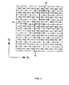
- Fig. 1 illustrates a system for generating a screened reproduction of an image constructed and operative in accordance with a preferred embodiment of the present invention.
- the system preferably comprises a color separation scanner 10, such as a Scitex Smart Scanner, manufactured and sold by Scitex Corporation Ltd. of Herzlia, Israel, which is adapted to provide a digital color separation output of a color original.
- a color separation scanner 10 such as a Scitex Smart Scanner, manufactured and sold by Scitex Corporation Ltd. of Herzlia, Israel, which is adapted to provide a digital color separation output of a color original.
- the digital output of scanner 10 is normally stored on a image data disc 12 or any other suitable storage medium, which is accessible by a CPU 14, such as an Intel 80386.
- a CPU 14 such as an Intel 80386.
- Interfacing with the CPU 14 is an interactive workstation 16, such as a Scitex Prisma, manufactured and sold by Scitex Corporation Ltd. of Herzlia, Israel.
- CPU 14 interfaces with screen dot generation circuitry 18, which in turn provides a control output to laser beam control circuitry 24 in a laser plotter 26, such as a Raystar, manufactured and sold by Scitex Corporation Ltd. of Herzlia, Israel.
- Laser plotter 26 produces halftone film color separations 28 which are employed in a conventional process color printing press 30, to produce process color prints.
- Fig. 2 illustrates a typical halftone color separation which is stored on disc 12.
- Fig. 3 illustrates in enlarged detail, a small area 32 indicated on Fig. 2. It is noted that the gray level over area 32 varies thereacross.
- the halftone color separation in general and the small area 32 in particular are hereinafter termed the input image and are divided into a first multiplicity of pixels 34 which are arranged along coordinates I x and I y .
- Pixels 34 typically have a resolution of 100 - 400 pixels per inch along one of the coordinate axes of the input image.
- Each average gray level for a pixel 34 is represented digitally by an input density level. There are typically provided 256 different input density levels, 0 being the lightest and 255 being the blackest.
- Fig. 4 illustrates the input density values for the pixels 34 of Fig. 3.
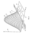
- Fig. 5 illustrates an output dot density threshold distribution 40 for a conventional dot which is used in process color printing.
- distribution 40 there is illustrated part of the input density map of Fig. 4, corresponding to a region there identified by reference numeral 42. It is noted that region 42 includes different density values for different input pixels 34.
- the output dot density threshold distribution 40 is a three dimensional representation of a screen dot arrangement, including a two dimensional space 44 corresponding to the spatial dimensions of the image and a one dimensional value 46 corresponding to the dot density threshold value at each spatial location thereon.
- Distribution 40 defines a plurality of sections 48 at a selected angle a in the two dimensional space, corresponding to a screening angle, here 90 degrees, for example.
- the sections 48 are at a section-to-section spacing 50 corresponding to the line to line writing resolution of a plotter, typically 800 - 5000 lines per inch, each section defining threshold values for locations along a line 52 in the two dimensional space.
- a collection of points such as those indicated on distribution 40, illustrate values in the three dimensional space which are stored to define the distribution.
- functions which define, inter alia, the collection of points may be stored to define the distribution. It will thus be appreciated that in accordance with a preferred embodiment of the present invention and in contrast to the prior art, the screen dot thresholds are stored either as analog functions or as discrete values in three dimensional space representing such functions.
- the stored functions or points are used to calculate suitable sections 48 represented by points 54 thereon, corresponding to a selected resolution, mesh (screen dots per unit length) and screen angle. This calculation may involve extrapolation or interpolation as appropriate and is carried out in CPU 14, typically off line.
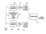
- a screen memory 60 the points 54 are supplied to a screen memory 60, and the input density values of pixels 34 are supplied to a picture memory 62.
- Screen memory 60 and picture memory 62 are typically controlled by a read/write and timing control unit 61 described in more detail in Fig. 8.
- memories 60 and 62 are supplied via respective digital to analog converters 64 and 66 to respective low pass filters 68 and 70. It is noted that under certain circumstances, low pass filter 70 may be omitted.
- low pass filter 68 is adapted to extrapolate and interpolate the points 54 stored in memory 60 so as to provide an accurate reproduction of the dot density threshold.
- the inclusion of low pass filter 70 depends on the quality of the input image.
- the outputs of low pass filters 68 and 70 are supplied to a comparator 72, which provides an output indication to expose control circuitry 24, indicating when the laser plotter 26 is to write. It is noted that there may also be provided various additional control functions, such as intensity control, to enhance the operation of the laser plotter 26.
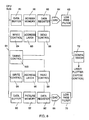
- read/write and timing control unit 61 comprises data buffers 81 and 90, data registers 83 and 92, write control units 84 and 94, address latches 86 and 96 and read control units 88 and 98 for controlling screen memory 60 and picture memory 62, respectively.
- a timing control unit 100 controls the timing of the signals sent to the digital to analog converters 64 and 66.
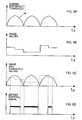
- the analog output of converter 64 for an example multiplicity of screen dots stored in screen memory 60 is shown in Fig. 9A and the analog output of converter 66 for an example plurality of input density values stored in picture memory 62 is shown in Fig. 9B.
- Fig. 9C illustrates the operation of comparator 72 in comparing the two signals shown in Figs. 9A and 9B, where the signal of Fig. 9B is shown as a dotted line.
- Fig. 9D illustrates the resultant signal produced by the comparator 72 and used to drive expose control circuitry 24.
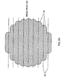
- Fig. 6A illustrates the construction of an output screen dot for a portion 80 of the image illustrated in Figs. 3 and 4.
- the input density values for the pixels 34 are indicated within each pixel and it is seen that they are all uniform.
- the laser plotter 26 defines a plurality of parallel lines 82, having a spacing 50, and whose beginning and end are determined by the output of comparator 72.
- the screen dot is a composite of such lines.
- the dot will have a generally symmetrical shape, as illustrated.
- each written line has infinite resolution along its length, because the on/off control inputs to the laser plotter are arrived at by comparison of two generally continuous analog signals.
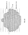
- Fig. 6B illustrates the construction of an output dot for portion 42 of the image illustrated in Figs. 3 and 4.
- the input density values for the pixels 34 are indicated within each pixel in Fig. 4 and it is seen that they differ from each other.
- the length of the lines 82 along each portion of the dot is a function of the input density value for the pixel 34 over which such lines lie.
- the dot lines 82 correspond to a relatively small dot area and where the input density value is high, such as 150, the dot lines 82 correspond to a relatively large dot area.
- An output dot which overlies pixels 34 having different input density values is thus asymmetric in a manner generally corresponding to the asymmetry of the input density values of the pixels 34 represented by the output dot.
Abstract
Description
- The present invention relates to screened image reproduction and more particularly to a method and apparatus for electronically generating a screened reproduction of an image.
- Electronic screening for image reproduction is well known in the art. According to a well known technique described in U.S. Patent 4,456,924 of the present assignee, for each screened dot, a multiplicity of coordinates of a laser plotter are translated into screen-cell coordinates. A corresponding cell memory is preloaded by threshold values, defining a cell memory matrix. Input digitized scanned density values of an image, such as a color separation, are compared with the threshold values, cell by cell. The results provide a on/off control input for a laser plotter.
- U.S. Patent 4,149,183 describes an electronic halftone generator wherein a halftone signal is generated by pulse width modulating or comparing the scanned or video signal with a periodic analog signal having two frequencies and phases to create a dot pattern output which is a function of the frequency and phase of the two combined modulating signals. The halftone reproduction generated has variable dot configurations that are controllable to enable both rotation of the dot pattern and geometric modifications of the dot pattern.
- The present invention seeks to provide an improved technique for generating a screened reproduction of an image.
- There is thus provided in accordance with a preferred embodiment of the present invention a technique for generating a screened reproduction of an image comprising the steps of:
providing a representation of an original having input density values representing the grey levels of various locations of the original for a given color separation,
defining a desired screen dot arrangement for the image,
writing screen dots in a line by line fashion, wherein each screen dot is made up of a plurality of lines whose length and location determines the dot configuration and whose length and location is determined by an analog operation employing the input density values of the original and the desired screen dot arrangement. - In accordance with a preferred embodiment of the present invention, each written line has infinite resolution along its length.
- Further in accordance with a preferred embodiment of the invention, the analog operation comprises an analog comparison of the input density values with threshold values defined by the desired screen dot arrangement.
- Additionally in accordance with an embodiment of the present invention, the step of writing screen dots includes the following steps:
storing the input density values of the original at a first spatial resolution and
storing the threshold values of the desired screen dot arrangement at a second spatial resolution different from the first resolution. - In accordance with a preferred embodiment of the invention, the second resolution corresponds to the line to line spatial resolution of a plotter used for writing the screen dots.
- Further in accordance with an embodiment of the invention, the step of storing the threshold values of the desired screen dot for a given line includes digitally storing the values at a third sampling resolution, which may be different from said first and second resolutions.
- Additionally in accordance with an embodiment of the invention, the step of writing screen dots includes the following steps:
prior to plotting, defining a three dimensional representation of a screen dot arrangement, including a two dimensional space corresponding to the spatial dimensions of the image and a one dimensional value corresponding to the dot threshold value at each spatial location thereon, and a plurality of sections at a selected angle in the two dimensional space, corresponding to a screening angle, and a section-to-section spacing corresponding to the line to line writing resolution of a plotter, each section defining threshold values for locations along a line in the two dimensional space and
thereafter comparing in an analog manner the input density values along the line with the threshold values of the coresponding section to determine the length and location of each written line produced by the plotter. - There is also provided in accordance with a preferred embodiment of the invention apparatus for generating a screened reproduction of an image comprising:
apparatus for providing a representation of an original having input density values representing the grey levels of various locations of the original for a given color separation,
apparatus for defining a desired screen dot arrangement for the image, and
apparatus for writing screen dots in a line by line fashion, wherein each screen dot is made up of a plurality of lines whose length and location determines the dot configuration and whose length and location is determined by an analog operation employing the input density values of the original and the desired screen dot arrangement. - Preferably the apparatus for writing screen dots includes:
apparatus for storing the input density values of the original at a first spatial resolution, and
apparatus for storing the threshold values of the desired screen dot arrangement at a second spatial resolution different from the first resolution. - In accordance with an embodiment of the invention the apparatus for storing the threshold values of the desired screen dot for a given line includes means for digitally storing the values at a third sampling resolution, which may be different from the first and second resolutions.
- In accordance with a preferred embodiment of the present invention, the apparatus for writing screen dots includes:
apparatus for defining, prior to plotting, a three dimensional representation of a screen dot arrangement, including a two dimensional space corresponding to the spatial dimensions of the image and a one dimensional value corresponding to the dot threshold value at each spatial location thereon, and a plurality of sections at a selected angle in the two dimension space, corresponding to a screening angle, and a section-to-section spacing corresponding to the line to line writing resolution of a plotter, each section defining threshold values for locations along a line in the two dimensional space, and
apparatus for thereafter comparing in an analog manner the input density values along the line with the threshold values of the coresponding section to determine the length and location of each written line produced by the plotter. - The present invention will be more fully understood and appreciated from the following detailed description, taken in conjunction with the drawings in which:
- Fig. 1 is a simplified block diagram illustration of a process color printing system constructed and operative in accordance with a preferred embodiment of the present invention;
- Fig. 2 is an illustration of one color separation of a typical color original;
- Fig. 3 is an enlarged illustration of a small portion of the halftone color separation of Fig. 2;
- Fig. 4 is an illustration of pixel-by-pixel input density values for the small portion of the color separation of Fig. 2;
- Fig. 5 is a more detailed illustration of the configuration of screen dots in three dimensional space superimposed on part of the illustration of Fig. 4;
- Fig. 6A is an even more detailed illustration of a line by line written screen dot produced in accordance with a preferred embodiment of the invention for a uniform input density;
- Fig. 6B is an even more detailed illustration of a line by line written screen dot produced in accordance with a preferred embodiment of the invention for a non-uniform input density;
- Fig. 7 is a simplified block diagram illustration of apparatus for screen dot generation operative in accordance with a preferred embodiment of the invention;
- Fig. 8 is a more detailed simplified block diagram of the apparatus for screen dot generation of Fig. 7; and
- Figs. 9A - 9D are simplified timing diagrams illustrating the operation of the circuitry of Fig. 8.
- Reference is now made to Fig. 1, which illustrates a system for generating a screened reproduction of an image constructed and operative in accordance with a preferred embodiment of the present invention. The system preferably comprises a
color separation scanner 10, such as a Scitex Smart Scanner, manufactured and sold by Scitex Corporation Ltd. of Herzlia, Israel, which is adapted to provide a digital color separation output of a color original. - The digital output of
scanner 10 is normally stored on aimage data disc 12 or any other suitable storage medium, which is accessible by aCPU 14, such as an Intel 80386. Interfacing with theCPU 14 is aninteractive workstation 16, such as a Scitex Prisma, manufactured and sold by Scitex Corporation Ltd. of Herzlia, Israel. -
CPU 14 interfaces with screendot generation circuitry 18, which in turn provides a control output to laserbeam control circuitry 24 in alaser plotter 26, such as a Raystar, manufactured and sold by Scitex Corporation Ltd. of Herzlia, Israel. -
Laser plotter 26 produces halftonefilm color separations 28 which are employed in a conventional processcolor printing press 30, to produce process color prints. - Reference is now made to Figs. 2 and 3. Fig. 2 illustrates a typical halftone color separation which is stored on
disc 12. Fig. 3 illustrates in enlarged detail, asmall area 32 indicated on Fig. 2. It is noted that the gray level overarea 32 varies thereacross. - The halftone color separation in general and the
small area 32 in particular are hereinafter termed the input image and are divided into a first multiplicity ofpixels 34 which are arranged along coordinates Ix and Iy. Pixels 34 typically have a resolution of 100 - 400 pixels per inch along one of the coordinate axes of the input image. - Each average gray level for a
pixel 34 is represented digitally by an input density level. There are typically provided 256 different input density levels, 0 being the lightest and 255 being the blackest. Fig. 4 illustrates the input density values for thepixels 34 of Fig. 3. - Fig. 5 illustrates an output dot
density threshold distribution 40 for a conventional dot which is used in process color printing. Alongsidedistribution 40 there is illustrated part of the input density map of Fig. 4, corresponding to a region there identified byreference numeral 42. It is noted thatregion 42 includes different density values fordifferent input pixels 34. - The output dot
density threshold distribution 40 is a three dimensional representation of a screen dot arrangement, including a twodimensional space 44 corresponding to the spatial dimensions of the image and a onedimensional value 46 corresponding to the dot density threshold value at each spatial location thereon.Distribution 40 defines a plurality ofsections 48 at a selected angle a in the two dimensional space, corresponding to a screening angle, here 90 degrees, for example. Thesections 48 are at a section-to-section spacing 50 corresponding to the line to line writing resolution of a plotter, typically 800 - 5000 lines per inch, each section defining threshold values for locations along aline 52 in the two dimensional space. - A collection of points, such as those indicated on
distribution 40, illustrate values in the three dimensional space which are stored to define the distribution. Alternatively functions which define, inter alia, the collection of points may be stored to define the distribution. It will thus be appreciated that in accordance with a preferred embodiment of the present invention and in contrast to the prior art, the screen dot thresholds are stored either as analog functions or as discrete values in three dimensional space representing such functions. - The stored functions or points are used to calculate
suitable sections 48 represented bypoints 54 thereon, corresponding to a selected resolution, mesh (screen dots per unit length) and screen angle. This calculation may involve extrapolation or interpolation as appropriate and is carried out inCPU 14, typically off line. - Referring now additionally to Fig. 7, it will be understood that the
points 54 are supplied to ascreen memory 60, and the input density values ofpixels 34 are supplied to apicture memory 62.Screen memory 60 andpicture memory 62 are typically controlled by a read/write andtiming control unit 61 described in more detail in Fig. 8. - The contents of
memories analog converters low pass filter 70 may be omitted. - It will be appreciated that the
low pass filter 68 is adapted to extrapolate and interpolate thepoints 54 stored inmemory 60 so as to provide an accurate reproduction of the dot density threshold. The inclusion oflow pass filter 70 depends on the quality of the input image. - The outputs of low pass filters 68 and 70 are supplied to a
comparator 72, which provides an output indication to exposecontrol circuitry 24, indicating when thelaser plotter 26 is to write. It is noted that there may also be provided various additional control functions, such as intensity control, to enhance the operation of thelaser plotter 26. - Reference is now made to Figs. 8 and 9A - 9D which respectively are a more detailed illustration of the circuitry of Fig. 7 and a timing diagram therefor. As can be seen from Fig. 8, read/write and
timing control unit 61 comprises data buffers 81 and 90, data registers 83 and 92, writecontrol units control units screen memory 60 andpicture memory 62, respectively. Atiming control unit 100 controls the timing of the signals sent to the digital toanalog converters - The analog output of
converter 64 for an example multiplicity of screen dots stored inscreen memory 60 is shown in Fig. 9A and the analog output ofconverter 66 for an example plurality of input density values stored inpicture memory 62 is shown in Fig. 9B. - Fig. 9C illustrates the operation of
comparator 72 in comparing the two signals shown in Figs. 9A and 9B, where the signal of Fig. 9B is shown as a dotted line. Fig. 9D illustrates the resultant signal produced by thecomparator 72 and used to driveexpose control circuitry 24. - Reference is now made to Fig. 6A, which illustrates the construction of an output screen dot for a
portion 80 of the image illustrated in Figs. 3 and 4. The input density values for thepixels 34 are indicated within each pixel and it is seen that they are all uniform. - The
laser plotter 26 defines a plurality ofparallel lines 82, having a spacing 50, and whose beginning and end are determined by the output ofcomparator 72. The screen dot is a composite of such lines. In a case wherein the input density values represented by the dot, i.e. in the twodimensional space 42 underlying thedensity threshold distribution 40 in Fig. 5, are uniform, the dot will have a generally symmetrical shape, as illustrated. - In accordance with a preferred embodiment of the present invention, each written line has infinite resolution along its length, because the on/off control inputs to the laser plotter are arrived at by comparison of two generally continuous analog signals.
- Reference is now made to Fig. 6B, which illustrates the construction of an output dot for
portion 42 of the image illustrated in Figs. 3 and 4. The input density values for thepixels 34 are indicated within each pixel in Fig. 4 and it is seen that they differ from each other. - It is appreciated from a consideration of Fig. 6B that the length of the
lines 82 along each portion of the dot is a function of the input density value for thepixel 34 over which such lines lie. Thus, where the input density value is relatively low, such as 100, thedot lines 82 correspond to a relatively small dot area and where the input density value is high, such as 150, thedot lines 82 correspond to a relatively large dot area. An output dot which overliespixels 34 having different input density values is thus asymmetric in a manner generally corresponding to the asymmetry of the input density values of thepixels 34 represented by the output dot. - It will be appreciated by persons skilled in the art that the present invention is not limited by what has been particularly shown and described hereinabove. Rather the scope of the present invention is defined only by the claims which follow:
Claims (14)
- A technique for generating a screened reproduction of an image comprising the steps of:
providing a representation of an original having input density values representing the grey levels of various locations of the original for a given color separation;
defining a desired screen dot arrangement for the image; and
writing screen dots in a line by line fashion, wherein each screen dot is made up of a plurality of lines whose length and location determines the dot configuration and whose length and location is determined by an analog operation employing the input density values of the original and the desired screen dot arrangement. - A technique according to claim 1 and wherein each of said plurality of lines has infinite resolution along its length.
- A technique according to claim 1 and wherein said analog operation comprises an analog comparison of the input density values with threshold values defined by the desired screen dot arrangement.
- A technique according to claim 1 and wherein said step of writing screen dots includes the following steps:
storing the input density values of the original at a first spatial resolution; and
storing the threshold values of the desired screen dot arrangement at a second spatial resolution different from the first resolution. - A technique according to claim 4 and wherein the second spatial resolution corresponds to the line to line spatial resolution of a plotter used for writing the screen dots.
- A technique according to claim 4 and wherein the step of storing the threshold values of the desired screen dot for a given line includes the step of digitally storing the values at a third sampling resolution, which may be different from said first and second resolutions.
- A technique according to claim 1 and wherein the step of writing screen dots includes the following steps:
prior to plotting, defining a three dimensional representation of a screen dot arrangement, including a two dimensional space corresponding to the spatial dimensions of the image and a one dimensional value corresponding to the dot threshold value at each spatial location thereon, and a plurality of sections at a selected angle in the two dimensional space, corresponding to a screening angle, and a section-to-section spacing corresponding to the line to line writing resolution of a plotter, each section defining threshold values for locations along a line in the two dimensional space; and
thereafter comparing in an analog manner the input density values along the line with the threshold values of the coresponding section to determine the length and location of each written line produced by the plotter. - Apparatus for generating a screened reproduction of an image comprising:
means for providing a representation of an original having input density values representing the grey levels of various locations of the original for a given color separation;
means for defining a desired screen dot arrangement for the image; and
means for writing screen dots in a line by line fashion, wherein each screen dot is made up of a plurality of lines whose length and location determines the dot configuration and whose length and location is determined by an analog operation employing the input density values of the original and the desired screen dot arrangement. - Apparatus according to claim 8 and wherein each of said plurality of lines has infinite resolution along its length.
- Apparatus according to claim 8 and wherein said analog operation comprises an analog comparison of the input density values with threshold values defined by the desired screen dot arrangement.
- Apparatus according to claim 8 and wherein said means for of writing screen dots includes:
means for storing the input density values of the original at a first spatial resolution; and
means for storing the threshold values of the desired screen dot arrangement at a second spatial resolution different from the first resolution. - Apparatus according to claim 11 and wherein the second resolution corresponds to the line to line spatial resolution of a plotter used for writing the screen dots.
- Apparatus according to claim 11 and wherein the means for storing the threshold values of the desired screen dot for a given line includes means for digitally storing the values at a third sampling resolution, which may be different from said first and second resolutions.
- Apparatus according to claim 8 and wherein the means for writing screen dots includes:
means for defining, prior to plotting, a three dimensional representation of a screen dot arrangement, including a two dimensional space corresponding to the spatial dimensions of the image and a one dimensional value corresponding to the dot threshold value at each spatial location thereon, and a plurality of sections at a selected angle in the two dimensional space, corresponding to a screening angle, and a section-to-section spacing corresponding to the line to line writing resolution of a plotter, each section defining threshold values for locations along a line in the two dimensional space; and
means for thereafter comparing in an analog manner the input density values along the line with the threshold values of the coresponding section to determine the length and location of each written line produced by the plotter.
Applications Claiming Priority (2)
| Application Number | Priority Date | Filing Date | Title |
|---|---|---|---|
| US524859 | 1983-08-19 | ||
| US07/524,859 US5079721A (en) | 1990-05-18 | 1990-05-18 | Apparatus for generating a screened reproduction of an image |
Publications (3)
| Publication Number | Publication Date |
|---|---|
| EP0457519A2 true EP0457519A2 (en) | 1991-11-21 |
| EP0457519A3 EP0457519A3 (en) | 1993-03-03 |
| EP0457519B1 EP0457519B1 (en) | 1997-06-25 |
Family
ID=24090945
Family Applications (1)
| Application Number | Title | Priority Date | Filing Date |
|---|---|---|---|
| EP91304244A Expired - Lifetime EP0457519B1 (en) | 1990-05-18 | 1991-05-10 | Apparatus for generating a screened reproduction of an image |
Country Status (8)
| Country | Link |
|---|---|
| US (1) | US5079721A (en) |
| EP (1) | EP0457519B1 (en) |
| JP (1) | JPH05336352A (en) |
| AT (1) | ATE154864T1 (en) |
| CA (1) | CA2042766A1 (en) |
| DE (1) | DE69126639T2 (en) |
| HK (1) | HK1005200A1 (en) |
| IL (1) | IL98113A (en) |
Families Citing this family (9)
| Publication number | Priority date | Publication date | Assignee | Title |
|---|---|---|---|---|
| GB9002475D0 (en) * | 1990-02-05 | 1990-04-04 | Crosfield Electronics Ltd | Electronic brush generation |
| JPH077624A (en) * | 1991-09-09 | 1995-01-10 | Mitsubishi Paper Mills Ltd | Dot picture recording method |
| US5473733A (en) * | 1992-03-25 | 1995-12-05 | Scitex Corporation Ltd. | Technique for generating image reproduction |
| US5526143A (en) * | 1992-09-16 | 1996-06-11 | Scitex Corporation Ltd. | Apparatus and technique for generating a screened reproduction of an image |
| IL105530A (en) * | 1993-04-27 | 1996-08-04 | Scitex Corp Ltd | Apparatus and method for generating a screened reproduction of an image |
| IL106514A (en) * | 1993-07-28 | 1997-08-14 | Scitex Corp Ltd | Apparatus and method for screening images for reproduction |
| US5519792A (en) * | 1994-03-02 | 1996-05-21 | Scitex Corporation Ltd. | Method and apparatus for generating a screened reproduction of an image by digital interpolation |
| US5689623A (en) * | 1995-03-27 | 1997-11-18 | Optronics International Corporation | Spread spectrum digital screening |
| IL122902A0 (en) * | 1998-01-12 | 1998-08-16 | Scitex Corp Ltd | Method and apparatus for generating a screened reproduction of an image |
Citations (8)
| Publication number | Priority date | Publication date | Assignee | Title |
|---|---|---|---|---|
| US3916096A (en) * | 1973-02-13 | 1975-10-28 | Int Publishing Corp Ltd | Electronic screening |
| US4040094A (en) * | 1973-02-13 | 1977-08-02 | International Publishing Corporation Ltd. | Electronic screening |
| US4533941A (en) * | 1983-01-14 | 1985-08-06 | Coulter Systems Corporation | Method and apparatus for half-tone reproduction of a varying tone original image |
| GB2157119A (en) * | 1984-04-06 | 1985-10-16 | Dainippon Screen Mfg | Halftone dot generation in image reproduction |
| EP0141869B1 (en) * | 1983-11-14 | 1987-09-16 | DR.-ING. RUDOLF HELL GmbH | Method and apparatus for manufacturing screened printing forms |
| US4825298A (en) * | 1987-05-26 | 1989-04-25 | Dainippon Screen Mfg. Co., Ltd. | Halftone dot-generator and generating method |
| US4918622A (en) * | 1988-11-16 | 1990-04-17 | Eastman Kodak Company | Electronic graphic arts screener |
| US4924301A (en) * | 1988-11-08 | 1990-05-08 | Seecolor Corporation | Apparatus and methods for digital halftoning |
Family Cites Families (2)
| Publication number | Priority date | Publication date | Assignee | Title |
|---|---|---|---|---|
| US4149183A (en) * | 1976-05-21 | 1979-04-10 | Xerox Corporation | Electronic halftone generator |
| US4456924A (en) * | 1980-04-14 | 1984-06-26 | Scitex Corporation Ltd. | Screened image reproduction |
-
1990
- 1990-05-18 US US07/524,859 patent/US5079721A/en not_active Expired - Fee Related
-
1991
- 1991-05-10 AT AT91304244T patent/ATE154864T1/en not_active IP Right Cessation
- 1991-05-10 DE DE69126639T patent/DE69126639T2/en not_active Expired - Fee Related
- 1991-05-10 EP EP91304244A patent/EP0457519B1/en not_active Expired - Lifetime
- 1991-05-12 IL IL9811391A patent/IL98113A/en active IP Right Grant
- 1991-05-16 CA CA002042766A patent/CA2042766A1/en not_active Abandoned
- 1991-05-17 JP JP3141239A patent/JPH05336352A/en active Pending
-
1998
- 1998-05-19 HK HK98104332A patent/HK1005200A1/en not_active IP Right Cessation
Patent Citations (8)
| Publication number | Priority date | Publication date | Assignee | Title |
|---|---|---|---|---|
| US3916096A (en) * | 1973-02-13 | 1975-10-28 | Int Publishing Corp Ltd | Electronic screening |
| US4040094A (en) * | 1973-02-13 | 1977-08-02 | International Publishing Corporation Ltd. | Electronic screening |
| US4533941A (en) * | 1983-01-14 | 1985-08-06 | Coulter Systems Corporation | Method and apparatus for half-tone reproduction of a varying tone original image |
| EP0141869B1 (en) * | 1983-11-14 | 1987-09-16 | DR.-ING. RUDOLF HELL GmbH | Method and apparatus for manufacturing screened printing forms |
| GB2157119A (en) * | 1984-04-06 | 1985-10-16 | Dainippon Screen Mfg | Halftone dot generation in image reproduction |
| US4825298A (en) * | 1987-05-26 | 1989-04-25 | Dainippon Screen Mfg. Co., Ltd. | Halftone dot-generator and generating method |
| US4924301A (en) * | 1988-11-08 | 1990-05-08 | Seecolor Corporation | Apparatus and methods for digital halftoning |
| US4918622A (en) * | 1988-11-16 | 1990-04-17 | Eastman Kodak Company | Electronic graphic arts screener |
Also Published As
| Publication number | Publication date |
|---|---|
| ATE154864T1 (en) | 1997-07-15 |
| IL98113A0 (en) | 1992-06-21 |
| IL98113A (en) | 1998-09-24 |
| HK1005200A1 (en) | 1998-12-24 |
| EP0457519A3 (en) | 1993-03-03 |
| DE69126639D1 (en) | 1997-07-31 |
| US5079721A (en) | 1992-01-07 |
| JPH05336352A (en) | 1993-12-17 |
| CA2042766A1 (en) | 1991-11-19 |
| DE69126639T2 (en) | 1997-10-23 |
| EP0457519B1 (en) | 1997-06-25 |
Similar Documents
| Publication | Publication Date | Title |
|---|---|---|
| EP0262801B1 (en) | Method or system for processing image data | |
| US5553171A (en) | Apparatus and method for arbitrary binary resolution conversion | |
| US5111194A (en) | Artificial halftone processing apparatus | |
| US5313309A (en) | Method and apparatus for printing halftones with a gray level printer with contour suppression and/or minimization of moire patterns | |
| EP0457519B1 (en) | Apparatus for generating a screened reproduction of an image | |
| JPH0683356B2 (en) | Image information recording device | |
| US5150225A (en) | Apparatus for generating a screened reproduction of an image | |
| JP2898061B2 (en) | Printing control method and apparatus and printing apparatus | |
| EP0016299A1 (en) | System for and method of reproducing an image | |
| JP4335394B2 (en) | Method and apparatus for rotating a highly addressable binary image | |
| US5227895A (en) | Method and apparatus for image reproduction | |
| EP0342845A1 (en) | Producing half-tone images | |
| JPH07123262A (en) | Method and device for reproducing image on screen | |
| US5299020A (en) | Method and apparatus for generating a screened reproduction of an image using stored dot portions | |
| EP0723362B1 (en) | Colour image forming apparatus | |
| US5519792A (en) | Method and apparatus for generating a screened reproduction of an image by digital interpolation | |
| US5508828A (en) | Apparatus and method for generating a screened reproduction of an image employing a non-periodic screen function | |
| EP0588566B1 (en) | Apparatus and technique for generating a screened reproduction of an image | |
| GB2121658A (en) | Mapping ram for a modulated display | |
| US5600448A (en) | Apparatus and method for generating a screened reproduction of an image | |
| EP0667705A1 (en) | Method and apparatus for generating a screened reproduction of an image | |
| US6049395A (en) | Method and system for achieving enhanced gray levels in a screen cell array | |
| JPH0698154A (en) | Dot recorder | |
| JPH07195746A (en) | Extra-high sensitivity printing system | |
| CA2128994A1 (en) | Variable resolution processing in a hyperacuity printer |
Legal Events
| Date | Code | Title | Description |
|---|---|---|---|
| PUAI | Public reference made under article 153(3) epc to a published international application that has entered the european phase |
Free format text: ORIGINAL CODE: 0009012 |
|
| AK | Designated contracting states |
Kind code of ref document: A2 Designated state(s): AT BE CH DE DK ES FR GB GR IT LI LU NL SE |
|
| 17P | Request for examination filed |
Effective date: 19921028 |
|
| PUAL | Search report despatched |
Free format text: ORIGINAL CODE: 0009013 |
|
| AK | Designated contracting states |
Kind code of ref document: A3 Designated state(s): AT BE CH DE DK ES FR GB GR IT LI LU NL SE |
|
| 17Q | First examination report despatched |
Effective date: 19950522 |
|
| GRAG | Despatch of communication of intention to grant |
Free format text: ORIGINAL CODE: EPIDOS AGRA |
|
| GRAH | Despatch of communication of intention to grant a patent |
Free format text: ORIGINAL CODE: EPIDOS IGRA |
|
| GRAH | Despatch of communication of intention to grant a patent |
Free format text: ORIGINAL CODE: EPIDOS IGRA |
|
| GRAA | (expected) grant |
Free format text: ORIGINAL CODE: 0009210 |
|
| AK | Designated contracting states |
Kind code of ref document: B1 Designated state(s): AT BE CH DE DK ES FR GB GR IT LI LU NL SE |
|
| PG25 | Lapsed in a contracting state [announced via postgrant information from national office to epo] |
Ref country code: IT Free format text: LAPSE BECAUSE OF FAILURE TO SUBMIT A TRANSLATION OF THE DESCRIPTION OR TO PAY THE FEE WITHIN THE PRE;WARNING: LAPSES OF ITALIAN PATENTS WITH EFFECTIVE DATE BEFORE 2007 MAY HAVE OCCURRED AT ANY TIME BEFORE 2007. THE CORRECT EFFECTIVE DATE MAY BE DIFFERENT FROM THE ONE RECORDED.SCRIBED TIME-LIMIT Effective date: 19970625 Ref country code: LI Free format text: LAPSE BECAUSE OF FAILURE TO SUBMIT A TRANSLATION OF THE DESCRIPTION OR TO PAY THE FEE WITHIN THE PRESCRIBED TIME-LIMIT Effective date: 19970625 Ref country code: ES Free format text: THE PATENT HAS BEEN ANNULLED BY A DECISION OF A NATIONAL AUTHORITY Effective date: 19970625 Ref country code: NL Free format text: LAPSE BECAUSE OF FAILURE TO SUBMIT A TRANSLATION OF THE DESCRIPTION OR TO PAY THE FEE WITHIN THE PRESCRIBED TIME-LIMIT Effective date: 19970625 Ref country code: CH Free format text: LAPSE BECAUSE OF FAILURE TO SUBMIT A TRANSLATION OF THE DESCRIPTION OR TO PAY THE FEE WITHIN THE PRESCRIBED TIME-LIMIT Effective date: 19970625 Ref country code: DK Effective date: 19970625 Ref country code: FR Effective date: 19970625 Ref country code: AT Effective date: 19970625 Ref country code: GR Free format text: LAPSE BECAUSE OF FAILURE TO SUBMIT A TRANSLATION OF THE DESCRIPTION OR TO PAY THE FEE WITHIN THE PRESCRIBED TIME-LIMIT Effective date: 19970625 |
|
| REF | Corresponds to: |
Ref document number: 154864 Country of ref document: AT Date of ref document: 19970715 Kind code of ref document: T |
|
| REG | Reference to a national code |
Ref country code: CH Ref legal event code: EP |
|
| REF | Corresponds to: |
Ref document number: 69126639 Country of ref document: DE Date of ref document: 19970731 |
|
| PG25 | Lapsed in a contracting state [announced via postgrant information from national office to epo] |
Ref country code: SE Effective date: 19970925 |
|
| EN | Fr: translation not filed | ||
| NLV1 | Nl: lapsed or annulled due to failure to fulfill the requirements of art. 29p and 29m of the patents act | ||
| REG | Reference to a national code |
Ref country code: CH Ref legal event code: PL |
|
| PLBE | No opposition filed within time limit |
Free format text: ORIGINAL CODE: 0009261 |
|
| STAA | Information on the status of an ep patent application or granted ep patent |
Free format text: STATUS: NO OPPOSITION FILED WITHIN TIME LIMIT |
|
| PG25 | Lapsed in a contracting state [announced via postgrant information from national office to epo] |
Ref country code: LU Free format text: LAPSE BECAUSE OF NON-PAYMENT OF DUE FEES Effective date: 19980510 |
|
| 26N | No opposition filed | ||
| PGFP | Annual fee paid to national office [announced via postgrant information from national office to epo] |
Ref country code: GB Payment date: 20000410 Year of fee payment: 10 |
|
| PGFP | Annual fee paid to national office [announced via postgrant information from national office to epo] |
Ref country code: DE Payment date: 20000422 Year of fee payment: 10 |
|
| PGFP | Annual fee paid to national office [announced via postgrant information from national office to epo] |
Ref country code: BE Payment date: 20000428 Year of fee payment: 10 |
|
| PG25 | Lapsed in a contracting state [announced via postgrant information from national office to epo] |
Ref country code: GB Free format text: LAPSE BECAUSE OF NON-PAYMENT OF DUE FEES Effective date: 20010510 |
|
| PG25 | Lapsed in a contracting state [announced via postgrant information from national office to epo] |
Ref country code: BE Free format text: LAPSE BECAUSE OF NON-PAYMENT OF DUE FEES Effective date: 20010531 |
|
| BERE | Be: lapsed |
Owner name: SCITEX CORP. LTD Effective date: 20010531 |
|
| GBPC | Gb: european patent ceased through non-payment of renewal fee |
Effective date: 20010510 |
|
| PG25 | Lapsed in a contracting state [announced via postgrant information from national office to epo] |
Ref country code: DE Free format text: LAPSE BECAUSE OF NON-PAYMENT OF DUE FEES Effective date: 20020301 |