EP0457940A1 - Activating circuit - Google Patents
Activating circuit Download PDFInfo
- Publication number
- EP0457940A1 EP0457940A1 EP90109653A EP90109653A EP0457940A1 EP 0457940 A1 EP0457940 A1 EP 0457940A1 EP 90109653 A EP90109653 A EP 90109653A EP 90109653 A EP90109653 A EP 90109653A EP 0457940 A1 EP0457940 A1 EP 0457940A1
- Authority
- EP
- European Patent Office
- Prior art keywords
- electronic device
- code
- module
- activating circuit
- activating
- Prior art date
- Legal status (The legal status is an assumption and is not a legal conclusion. Google has not performed a legal analysis and makes no representation as to the accuracy of the status listed.)
- Granted
Links
Images

Classifications
-
- G—PHYSICS
- G06—COMPUTING; CALCULATING OR COUNTING
- G06F—ELECTRIC DIGITAL DATA PROCESSING
- G06F8/00—Arrangements for software engineering
- G06F8/60—Software deployment
- G06F8/65—Updates
-
- G—PHYSICS
- G05—CONTROLLING; REGULATING
- G05B—CONTROL OR REGULATING SYSTEMS IN GENERAL; FUNCTIONAL ELEMENTS OF SUCH SYSTEMS; MONITORING OR TESTING ARRANGEMENTS FOR SUCH SYSTEMS OR ELEMENTS
- G05B19/00—Programme-control systems
- G05B19/02—Programme-control systems electric
- G05B19/04—Programme control other than numerical control, i.e. in sequence controllers or logic controllers
- G05B19/042—Programme control other than numerical control, i.e. in sequence controllers or logic controllers using digital processors
- G05B19/0426—Programming the control sequence
-
- G—PHYSICS
- G06—COMPUTING; CALCULATING OR COUNTING
- G06F—ELECTRIC DIGITAL DATA PROCESSING
- G06F21/00—Security arrangements for protecting computers, components thereof, programs or data against unauthorised activity
- G06F21/50—Monitoring users, programs or devices to maintain the integrity of platforms, e.g. of processors, firmware or operating systems
- G06F21/52—Monitoring users, programs or devices to maintain the integrity of platforms, e.g. of processors, firmware or operating systems during program execution, e.g. stack integrity ; Preventing unwanted data erasure; Buffer overflow
-
- G—PHYSICS
- G06—COMPUTING; CALCULATING OR COUNTING
- G06F—ELECTRIC DIGITAL DATA PROCESSING
- G06F21/00—Security arrangements for protecting computers, components thereof, programs or data against unauthorised activity
- G06F21/50—Monitoring users, programs or devices to maintain the integrity of platforms, e.g. of processors, firmware or operating systems
- G06F21/55—Detecting local intrusion or implementing counter-measures
- G06F21/56—Computer malware detection or handling, e.g. anti-virus arrangements
- G06F21/567—Computer malware detection or handling, e.g. anti-virus arrangements using dedicated hardware
-
- G—PHYSICS
- G05—CONTROLLING; REGULATING
- G05B—CONTROL OR REGULATING SYSTEMS IN GENERAL; FUNCTIONAL ELEMENTS OF SUCH SYSTEMS; MONITORING OR TESTING ARRANGEMENTS FOR SUCH SYSTEMS OR ELEMENTS
- G05B2219/00—Program-control systems
- G05B2219/20—Pc systems
- G05B2219/23—Pc programming
- G05B2219/23269—Program provides for communication protocol with device, equipment
-
- G—PHYSICS
- G05—CONTROLLING; REGULATING
- G05B—CONTROL OR REGULATING SYSTEMS IN GENERAL; FUNCTIONAL ELEMENTS OF SUCH SYSTEMS; MONITORING OR TESTING ARRANGEMENTS FOR SUCH SYSTEMS OR ELEMENTS
- G05B2219/00—Program-control systems
- G05B2219/20—Pc systems
- G05B2219/23—Pc programming
- G05B2219/23306—Load program from host, remote load, non volatile card to volatile, ram
-
- G—PHYSICS
- G05—CONTROLLING; REGULATING
- G05B—CONTROL OR REGULATING SYSTEMS IN GENERAL; FUNCTIONAL ELEMENTS OF SUCH SYSTEMS; MONITORING OR TESTING ARRANGEMENTS FOR SUCH SYSTEMS OR ELEMENTS
- G05B2219/00—Program-control systems
- G05B2219/20—Pc systems
- G05B2219/23—Pc programming
- G05B2219/23335—History, log of program modifications
-
- G—PHYSICS
- G05—CONTROLLING; REGULATING
- G05B—CONTROL OR REGULATING SYSTEMS IN GENERAL; FUNCTIONAL ELEMENTS OF SUCH SYSTEMS; MONITORING OR TESTING ARRANGEMENTS FOR SUCH SYSTEMS OR ELEMENTS
- G05B2219/00—Program-control systems
- G05B2219/20—Pc systems
- G05B2219/23—Pc programming
- G05B2219/23387—Trackball
-
- G—PHYSICS
- G05—CONTROLLING; REGULATING
- G05B—CONTROL OR REGULATING SYSTEMS IN GENERAL; FUNCTIONAL ELEMENTS OF SUCH SYSTEMS; MONITORING OR TESTING ARRANGEMENTS FOR SUCH SYSTEMS OR ELEMENTS
- G05B2219/00—Program-control systems
- G05B2219/20—Pc systems
- G05B2219/23—Pc programming
- G05B2219/23427—Selection out of several programs, parameters
-
- G—PHYSICS
- G05—CONTROLLING; REGULATING
- G05B—CONTROL OR REGULATING SYSTEMS IN GENERAL; FUNCTIONAL ELEMENTS OF SUCH SYSTEMS; MONITORING OR TESTING ARRANGEMENTS FOR SUCH SYSTEMS OR ELEMENTS
- G05B2219/00—Program-control systems
- G05B2219/20—Pc systems
- G05B2219/23—Pc programming
- G05B2219/23458—Remote controller pluggable, attachable to pc
-
- G—PHYSICS
- G05—CONTROLLING; REGULATING
- G05B—CONTROL OR REGULATING SYSTEMS IN GENERAL; FUNCTIONAL ELEMENTS OF SUCH SYSTEMS; MONITORING OR TESTING ARRANGEMENTS FOR SUCH SYSTEMS OR ELEMENTS
- G05B2219/00—Program-control systems
- G05B2219/20—Pc systems
- G05B2219/24—Pc safety
- G05B2219/24167—Encryption, password, user access privileges
-
- G—PHYSICS
- G05—CONTROLLING; REGULATING
- G05B—CONTROL OR REGULATING SYSTEMS IN GENERAL; FUNCTIONAL ELEMENTS OF SUCH SYSTEMS; MONITORING OR TESTING ARRANGEMENTS FOR SUCH SYSTEMS OR ELEMENTS
- G05B2219/00—Program-control systems
- G05B2219/20—Pc systems
- G05B2219/25—Pc structure of the system
- G05B2219/25092—Customized control features, configuration
-
- G—PHYSICS
- G05—CONTROLLING; REGULATING
- G05B—CONTROL OR REGULATING SYSTEMS IN GENERAL; FUNCTIONAL ELEMENTS OF SUCH SYSTEMS; MONITORING OR TESTING ARRANGEMENTS FOR SUCH SYSTEMS OR ELEMENTS
- G05B2219/00—Program-control systems
- G05B2219/20—Pc systems
- G05B2219/25—Pc structure of the system
- G05B2219/25175—Modem, codec coder decoder
-
- G—PHYSICS
- G05—CONTROLLING; REGULATING
- G05B—CONTROL OR REGULATING SYSTEMS IN GENERAL; FUNCTIONAL ELEMENTS OF SUCH SYSTEMS; MONITORING OR TESTING ARRANGEMENTS FOR SUCH SYSTEMS OR ELEMENTS
- G05B2219/00—Program-control systems
- G05B2219/20—Pc systems
- G05B2219/25—Pc structure of the system
- G05B2219/25192—Infrared
-
- G—PHYSICS
- G06—COMPUTING; CALCULATING OR COUNTING
- G06F—ELECTRIC DIGITAL DATA PROCESSING
- G06F2221/00—Indexing scheme relating to security arrangements for protecting computers, components thereof, programs or data against unauthorised activity
- G06F2221/21—Indexing scheme relating to G06F21/00 and subgroups addressing additional information or applications relating to security arrangements for protecting computers, components thereof, programs or data against unauthorised activity
- G06F2221/2153—Using hardware token as a secondary aspect
Definitions
- This invention relates to an activating circuit for an electronic device, said electronic device containing a processor and a memory and operating at least partially under program control.
- a multiplicity of electronic devices such as measuring devices, medical monitors or test devices, perform their functions nowadays under control of a microprocessor.
- the measurement pickups e.g. the test probe and the input amplifiers of an oscillograph or of a data bus analyzer, or the electrodes and the preamplifiers of a medical monitor - still consist of analog electronics
- more complex functions are performed by the microprocessor.
- Such functions include the guidance of the user through menus, windows or other techniques, complex mathematical or statistical operations, the presentation of certain measurement results (e.g. special graphics or the like), software filters (i.e.
- the microprocessor further controls the communication between certain components, e.g. PC boards or integrated circuits, of a system and the interfacing capabilities of the device (most devices of state of the art technology have the capability to communicate over standardized digital interfaces).
- Another reason for a software update may be that new features have been added to the existing program.
- new feature could include the support of a new interface, or the capability of the device to communicate with the user in another language.
- Such new feature may, of course, include free software updates as well as features which are sold as an option to the existing device (e.g. support of an additional pick-up).
- test software for all and every tests, in particular very special tests, in the standard software of the electronic device. Therefore, from time to time it is necessary to load special or extensive test programs in such devices.
- an activating circuit comprising:
- the activating circuit may be a separate, small module for connection with the electronic device as will be discussed later. Still there are also a multiplicity of other choices; for example, the activating circuit may also be or comprise a personal computer.
- the activating device contains a processor, typically a microprocessor with low power consumption.
- This processor has access to a non-volatile memory like a ROM (read-only-memory) or an EEROM (electrically erasable read-only-memory); preferably, the memory is integrated in the processor (many customary micro-processors, the so-called “one-chip-microprocessors", offer this feature).
- the activating circuit is further set up for connection to the electronic device, preferably via a cable; still there are also other solutions like wireless transmission, as will also be discussed later.
- the program contained in the non-volatile memory consists of at least two modules.
- the first of these modules sets up a communication with the electronic device. This may be a "hand-shake" procedure in asynchronous transmission format.
- the activating circuit transmits a start code to the electronic device, and further communication between the activating circuit and the electronic device is then performed according to a predefined protocol.
- synchronous transmission or other transmission methods are also suitable.
- control is transferred to a second module set up to transmit data and/or code to the electronic device.
- Said second module is actually provided for transmission of the data or the code which adds additional functionality to the device.
- said data may comprise new programs to be executed by the electronic device's processor.
- the new programs or parts of a new program, or new subroutines for existing programs
- the activating circuit just as data of any other kind, i.e. they are "downloaded" to the electronic device byte by byte.
- the receiving electronic device handles these data as program modules, i.e. stores them in the non-volatile program memory of its processor.
- the electronic device's processor executes these programs.
- the receiving electronic device treats the received data as programs or program modules; for example, the transmitted data may be identified by some special code as a program, or the communication may be set up in a way that only data representing a program can be transmitted.
- Another possibility of adding additional functionality to the electronic device is to activate existing programs or program modules. That is, the program memory of the electronic device's processor already contains the necessary software to perform certain functions upon delivery to a customer, but these programs or program modules cannot be accessed, i.e. are not active. Upon transmission of an activating code, the programs or program modules are unlocked and can now be executed by the electronic device's processor. This is an easy way of adding new functions to the electronic device; as only the activating code has to be transmitted, the communication between the activating circuit and the electronic device is very short and easy to implement.
- An activating circuit of the kind described above may be used to install additional features in an electronic device - such as a measuring instrument - in a very easy and cost-effective manner.
- One of the major advantages is that there is no need for a personal visit of a service engineer. This is particularly important for medical technology; the present invention offers for the first time a solution to activate additional features in a medical monitor without a service engineer's personal visit.
- the activating device is quite cheap to manufacture, particularly if a one-chip-microprocessor is used; instead, the activating device may also be a personal computer or the like which can be used to activate a multiplicity of electronic devices (which is an even cheaper solution).
- the activating circuit may, depending on each application, be used to transmit program code or an activating code; the purpose may be to add additional functions, special tests and the like.
- the activating circuit is characterized in that
- the first module compares an identification code received from the electronic device with an identification code stored in the erasable, non-volatile memory. If no such identification code is stored there, then the received identification code is stored in the memory. On the other hand, if an identification code is found in memory, it is compared to the received code, and the second module is only activated (i.e. data and/or code is only transmitted) if the identification codes are equal. If they are not equal, operation stops.
- the activating circuit can only be used to activate one electronic device provided that all electronic devices comprise different identification codes. If the activating circuit has once been connected with an electronic device, it has stored the identification code of this device and therefore can only be used in conjunction with this device in the future. It will not communicate with any other electronic device with a different identification code. It is understood that in such case the activating device's non-volatile memory has to be an erasable memory as the identification code has to be written into the memory the first time such code is received.
- the described embodiment offers the opportunity to sell and/or distribute an activating device which is suited to activate one electronic device only. Therefore, for every electronic device to be activated, a separate activating device has to be purchased.
- the activating device may be a small box containing a one-chip-microprocessor sold together with an operating guide. The customer is not able to use the activating circuit to activate more than one electronic device or to copy the program contained in the activating circuit.
- a service board may be used as replacement which transmits a special service identification code to the activating circuit.
- the activating circuit Once the activating circuit has received and stored such service identification code, it can be used in conjunction with all electronic devices containing a replacement board. Therefore, it is ensured that even in case of hardware malfunction the exchanged memories contain the same activated functions as were contained in the board which became defective.
- the activating device may be used in conjunction with only one electronic device.
- the identification code is used as a "key word" for the encoding algorithm. It is understood that, in this case, the activating circuit has to store the first received identification code, too, and to encode the transmitted information in dependency of such stored identification code.
- the electronic device is only capable of decoding the transmitted information if it contains the same identification code as stored in the activating circuit. According to this solution, the activating circuit may also be used in conjunction with only one electronic device because the others have different identification codes and therefore cannot decode received information.
- the first module is set up to receive a status code from the electronic device, to compare said status code with a stored update code and to transfer control to the second module only if said status code is in a predefined relation to said update code.
- the status code may e.g. represent a revision number or the date when the programs were released.
- the activating circuit is contained in a housing and connected with the electronic device via a cable and a connector.
- the activating circuit may be sold as a separate part only suited to activate one electronic device.
- the connection is made via a two-leaped serial interface cable. It is advantageous to use a microprocessor, preferably of the one-chip type with integrated non-volatile, erasable memory in this case as this reduces the number of components and therefore the costs.
- the activating circuit comprises a personal computer, and connection is made over telephone lines.
- connection is made over telephone lines. This is a very clever way of updating the electronic devices; a simple telephone connection has to be made between the electronic device and the personal computer in a factory, and the activating code or program may be downloaded over the telephone line.
- This solution requires no extra hardware, and the personal computer may be used to activate any electronic device even in remote distances.
- a further preferred solution provides an integrated microprocessor which constitutes the activating device.
- One-chip-microprocessors with integrated memory, even small ones with only four pins, are available on the market.
- Such microprocessor is inserted in a socket in the electronic device and transmits the necessary code to activate the wanted feature. It is particularly advantageous if the socket is placed behind a small door (which is normally closed) of the electronic device. In this case - as there is no need to open whole electronic device -, the microprocessor may be inserted by the customer which makes installation considerably cheaper.
- this processor is preferably of the low power consumption type. It is even possible that the processor receives the energy necessary for operation from the received data pulses.
- Fig. 1 depicts a medical monitor generally outlined as 1.
- the monitor consists of a box 2 and a display 3.
- Box 2 contains the necessary hardware like preamplifiers and analog signal processing circuits, the digital components, at least one microprocessor and the circuitry necessary to operate this processor, particularly certain memory circuits.
- the details of the front-end connection, in particular the transducers and their connection to box 2, are not shown in Fig. 1.
- Display 3 is used to present the results of the various measurements.
- ECG Electrocardiogram
- a blood pressure waveform 4b are depicted in Fig. 1.
- Display 3 further comprises several keys provided for user interaction. Some of these keys are labelled as 5a to 5d in Fig. 1. It is understood that an actual monitor provides more than the four keys shown in Fig. 1.
- Operation of medical monitor 1 is controlled by its internal processor.
- This processor performs a variety of functions, e.g. wave form filtering and digital signal processing, setting of alarm limits and generating an alarm when such limit is exceeded, lead selection if an ECG is displayed, communication with a recorder or a remote station and so on.
- Medical monitor 1 further comprises a jack 6, the function of which will be explained below.
- Fig. 1 further shows an activating circuit, here in form of a box 7.
- Box 7 contains a one-chip-microprocessor and the necessary peripheral hardware to control this processor as well as a serial interface. Said interface is connected with a cable 8 which ends in a connector 9.
- Box 7 is preferably used to add additional functionality to the programs contained in medical monitor 1, i.e. to provide new programs to this monitor.
- Box 7, cable 8 and connector 9 are separately sold in form of an "update kit" containing these components as well as an instruction sheet.
- the customer needs simply to connect box 7 with medical monitor 1, i.e. to put connector 9 in jack 6 as depicted by arrow 10.
- the memory provided with the microprocessor contained in box 7 comprises at least two modules, the first establishing a communication with medical monitor 1 and the second transmitting program code to said monitor. Once the first module has established the communication between the two devices, it transfers control to the second module which downloads the additional program code to medical monitor 1.
- the processor of monitor 1 is now able to execute the new program code, i.e. to establish the new functions provided by the downloaded programs.
- box 7 cannot only be used to download new programs, but also to activate programs which were already contained, but "hidden” in the software of medical monitor 1. Further, instead of adding new functionality, the downloaded programs or activating codes may be used to install or start special test sequences. Last not least, box 7 may also be used to exchange software containing a bug.
- the first module contained in box 7 may further comprise certain controlling functions ensuring that box 7 can only be used with one medical monitor. The operation of such controlling sequences will be explained by means of Fig. 6.
- FIG. 2 Another environment is depicted in Fig. 2.
- Medical monitor 1' is equipped with an antenna 11, and box 7' is also equipped with another antenna 12.
- communication between the medical monitor and the activating circuit as well as program/code download is performed using wireless transmission with electromagnetic waves.
- the other components of the medical monitor and the box may be similar as in the environment of Fig. 1. It is understood that wireless transmission may also be performed using infrared light or the like.
- Fig. 3 shows a further environment in which the activating circuit comprises a personal computer 13.
- the personal computer consists of computer box 14, display 15, keyboard 16 and other common components such as disc drives, a mouse etc. (not shown in Fig. 3).
- Personal computer 13 as well as medical monitor 1'' contain modems. Communication between the two devices is set up from the modem of monitor 1'' to a telephone 17, a telephone connection 18 and a second telephone 19 to the modem of personal computer 13 and vice versa.
- the environment depicted in Fig. 3 is especially suited if a program needs updating, i.e. if a software bug has been detected and the program has to be exchanged with a new revision in which these errors have been corrected.
- the environment of Fig. 3 allows to load the revised program on a multiplicity of monitors without the need to send a service engineer to every customer in possession of a monitor.
- Personal computer 13 is located in the manufacturer's building and may be used to update all monitors already distributed even if they are located in very remote places.
- Fig. 4 depicts a hardware box 2'' corresponding to hardware box 2 of medical monitor 1 in Fig. 1.
- cover 20 of this box is drawn in its open position.
- the hardware box contains a multiplicity of printed circuit boards 21a to 21e.
- Board 21a comprises an integrated circuit socket 22 which operates as connection means to the medical monitor.
- the activating circuit consists of a very small one-chip-microprocessor 23 with four pins (one for the supply voltage, one for ground, one for transmission and one for receive operation).
- Microprocessor 23 is delivered as an option to the medical monitor and is able to transmit program or activating codes according to the principles described herein.
- Socket 22 is normally hidden behind a small door 2''a. In order to install microprocessor 23, door 2''a has to be opened, and microprocessor 23 has to be inserted into socket 22. As box 2'' has not to be opened completely for this purpose, installation can be performed by the customer without the danger of causing electrical malfunction, particularly if socket 22 is appropriately isolated.
- Fig. 6 is a flow chart explaining the basic operating mode of the processor contained in the activating circuit.
- Two modules 24 and 25 perform data exchange between the activating circuit and the electronic device.
- module I Upon startup (reference number 26), module I initiates the communication with the electronic device (reference number 27).
- the next step is that the activating circuit receives the status code from the electronic device (28).
- This status code represents the status of the programs contained in the electronic device, either as a date code or as a revision number.
- the purpose of the status code is to ensure that programs or activating codes are only downloaded if the electronic device has not yet received the updated programs from another activating circuit.
- the activating circuit is prepared to communicate with one electronic device only because otherwise it may happen that a program is downloaded to an electronic device which already contains the downloaded programs - i.e. the transmission is useless -, and the activating circuit cannot be used in conjunction with another electronic device thereafter.
- step 29 the received status code is compared with the update code contained in the activating circuit, and in step 30 a decision is made whether an update is necessary in the light of the foregoing comparison. For example, if the status code and the update code contain the same date or revision number, this means that the electronic device's memory already contains the program which is to be downloaded, and therefore operation stops (reference number 31).
- step 32 i.e. the activating circuit receives an identification code from the electronic device.
- the identification code is a code unique for each electronic device, for example its serial number.
- step 33 A decision is then made (step 33) whether this is the first identification code ever received by the activating circuit. If the answer is "yes”, then this identification code is stored (step 34). If the answer is "no", the processor in the activating circuit checks whether the received identification code and the stored identification code are equal (step 35). In case they are not equal, this means that the activating circuit has already been used in conjunction with another electronic device and therefore cannot be used together with the present one. In this case, operation stops (step 36).
- control is transferred to module II which handles the transmission and data exchange between the activating circuit and the electronic device (step 37). This transmission is performed in known manner, i.e. using a handshake procedure.
- operation stops step 38.
Abstract
Description
- This invention relates to an activating circuit for an electronic device, said electronic device containing a processor and a memory and operating at least partially under program control.
- A multiplicity of electronic devices, such as measuring devices, medical monitors or test devices, perform their functions nowadays under control of a microprocessor. Although the measurement pickups - e.g. the test probe and the input amplifiers of an oscillograph or of a data bus analyzer, or the electrodes and the preamplifiers of a medical monitor - still consist of analog electronics, more complex functions are performed by the microprocessor. Such functions include the guidance of the user through menus, windows or other techniques, complex mathematical or statistical operations, the presentation of certain measurement results (e.g. special graphics or the like), software filters (i.e. software processing of data converted from analog to digital format), control of certain hardware components such as the amplification of an amplifier stage, setting the bandwidth of a hardware filter, control of an analog-to-digital converter, and the like. The microprocessor further controls the communication between certain components, e.g. PC boards or integrated circuits, of a system and the interfacing capabilities of the device (most devices of state of the art technology have the capability to communicate over standardized digital interfaces).
- These examples illustrate that a processor controlling an electronic device provides multiple complex functions. Therefore, the programs necessary for the processor are also very extensive and complex.
- However, implementation of such extensive software functions has caused new tasks and problems. For example, it is well-known in the art that an extensive program package is seldom completely free of software errors (so-called "bugs"). Although most software manufacturers try to test their programs under as many as possible and practically occurring conditions, it is simply impossible to test all combinations, external events and the like, particularly conditions which occur very seldom. Therefore, every complex program needs service; whenever one of these bugs has been detected, it has to be identified and corrected ("fixed"). The corrected program has then to be installed instead of the older version. This is the reason why most software suppliers, e.g. suppliers of operating systems, provide so-called "updates" to their programs. In the updated version, the bugs detected up to a certain point in time have been fixed.
- Another reason for a software update may be that new features have been added to the existing program. For example, such new feature could include the support of a new interface, or the capability of the device to communicate with the user in another language. Such new feature may, of course, include free software updates as well as features which are sold as an option to the existing device (e.g. support of an additional pick-up).
- Another case where additional program functionality is required is when an extensive test of the electronic device is to be carried out. Customary monitors and measuring instruments contain some test programs, e.g. a self-test of the memory and the input/output ports which is carried out when power is turned on. However, it is not possible or at least not economical to provide test software for all and every tests, in particular very special tests, in the standard software of the electronic device. Therefore, from time to time it is necessary to load special or extensive test programs in such devices.
- In the field of large and medium-sized computers, these problems are solved in two different ways:
- 1. In many cases, e.g. if the operating system needs update, the new or revised programs are implemented by a service technician. The technician carries the new programs to the customer using magnetic media (such as discs or tapes), puts them in a disc drive or a magnetic tape unit and loads the programs into the computer. This is a feasible solution for larger computers as the costs for the personal visit of the service technician are neglectable compared to the value of the whole computer. Further, computer software of this size needs service from time to time anyway, so that a regular service may be combined with the installation of additional or updated software.
- 2. If the revised, updated or additional programs belong to a less critical environment of the computer (i.e. programs which are not part of or related to the operating system such as application programs), then the programs may also be sent to the customer using magnetic media, and the customer may be asked to install these programs himself.
- Unfortunately, these solutions are not suitable or at least not cost-effective for measuring instruments, small computers and the like. The major reason therefore is that the expenses for a service technician's visit are not acceptable compared to the cost of the overall system. Further, the exchange of programs is often quite complicated from a technical standpoint. The reason therefore is that, in most of these devices, the programs are stored as so-called "firmware", i.e. the software is stored in read-only memory chips (ROMs). Therefore, any software change requires that the electronic device is disassembled and that certain memory chips (or even complete printed circuit boards) are exchanged. Even in cases where the device comprises a disc drive or a magnetic tape unit, part of the software (in particular, the basic loading and input/output routines) is stored in ROMs.
- On the other hand, as exchanging the ROMs requires disassembly of the device, such exchange can only be performed by a qualified service technician and cannot be left to the customer. Therefore, in regard of the extensive expenses, software updates of the kind described here have seldom been performed.
- The situation is even more critical in case of medical devices. In all such devices, it is absolutely unacceptable to have a software update made by the customer as an erroneous operation implies serious danger for the patient. For example, even a minor error could cause distortion of an alarm limit so that the medical device does not initiate an alarm when the patient is in clinically critical condition. This could even lead to the death of a patient. It is needless to say that this cannot be tolerated from a clinical standpoint. As a consequence, software updates incorporating new features have seldom been performed; in case that a software update has been necessary due to detected errors (bugs), such caused enormous costs for the manufacturing company and/or the customer.
- It is therefore a major object of the present invention to provide a solution which allows to implement new features or to update the programs in an electronic device, or to run extended test programs, which is technically easy to implement, cost-effective, easy to handle and usually does not require the visit of a service technician.
- According to the present invention, this is solved by an activating circuit comprising:
- a processor,
- a non-volatile memory,
- connection means for connecting the activating device with the electronic device and
- a program stored in said non-volatile memory, said program containing:
- a first module setting up a communication with the electronic device,
- a second module set up to transmit data and/or code to said electronic device.
- The activating circuit may be a separate, small module for connection with the electronic device as will be discussed later. Still there are also a multiplicity of other choices; for example, the activating circuit may also be or comprise a personal computer.
- The activating device contains a processor, typically a microprocessor with low power consumption. This processor has access to a non-volatile memory like a ROM (read-only-memory) or an EEROM (electrically erasable read-only-memory); preferably, the memory is integrated in the processor (many customary micro-processors, the so-called "one-chip-microprocessors", offer this feature).
- The activating circuit is further set up for connection to the electronic device, preferably via a cable; still there are also other solutions like wireless transmission, as will also be discussed later.
- The program contained in the non-volatile memory consists of at least two modules. The first of these modules sets up a communication with the electronic device. This may be a "hand-shake" procedure in asynchronous transmission format. Typically, the activating circuit transmits a start code to the electronic device, and further communication between the activating circuit and the electronic device is then performed according to a predefined protocol. On the other hand, synchronous transmission or other transmission methods are also suitable.
- Once the communication between the activating circuit and the electronic device is established, control is transferred to a second module set up to transmit data and/or code to the electronic device. Said second module is actually provided for transmission of the data or the code which adds additional functionality to the device.
- There are several possibilities of providing new functions to the processor of the electronic device. First, said data may comprise new programs to be executed by the electronic device's processor. In this case, the new programs (or parts of a new program, or new subroutines for existing programs) are handled by the activating circuit just as data of any other kind, i.e. they are "downloaded" to the electronic device byte by byte. However, the receiving electronic device handles these data as program modules, i.e. stores them in the non-volatile program memory of its processor. During operation, the electronic device's processor executes these programs. There are several ways to ensure that the receiving electronic device treats the received data as programs or program modules; for example, the transmitted data may be identified by some special code as a program, or the communication may be set up in a way that only data representing a program can be transmitted.
- Another possibility of adding additional functionality to the electronic device is to activate existing programs or program modules. That is, the program memory of the electronic device's processor already contains the necessary software to perform certain functions upon delivery to a customer, but these programs or program modules cannot be accessed, i.e. are not active. Upon transmission of an activating code, the programs or program modules are unlocked and can now be executed by the electronic device's processor. This is an easy way of adding new functions to the electronic device; as only the activating code has to be transmitted, the communication between the activating circuit and the electronic device is very short and easy to implement.
- An activating circuit of the kind described above may be used to install additional features in an electronic device - such as a measuring instrument - in a very easy and cost-effective manner. One of the major advantages is that there is no need for a personal visit of a service engineer. This is particularly important for medical technology; the present invention offers for the first time a solution to activate additional features in a medical monitor without a service engineer's personal visit. Further, the activating device is quite cheap to manufacture, particularly if a one-chip-microprocessor is used; instead, the activating device may also be a personal computer or the like which can be used to activate a multiplicity of electronic devices (which is an even cheaper solution). The activating circuit may, depending on each application, be used to transmit program code or an activating code; the purpose may be to add additional functions, special tests and the like.
- In a preferred embodiment, the activating circuit is characterized in that
- the first module is set up to receive an identification code from the electronic device,
- the activating circuit contains an erasable memory,
- the first module is set up to store the identification code in the erasable memory the first time it receives such identification code, and
- the first module is further set up to accept only the stored identification code and to prevent the second module from transmitting data and/or code to the electronic device if the identification codes are not equal.
- In this embodiment, the first module compares an identification code received from the electronic device with an identification code stored in the erasable, non-volatile memory. If no such identification code is stored there, then the received identification code is stored in the memory. On the other hand, if an identification code is found in memory, it is compared to the received code, and the second module is only activated (i.e. data and/or code is only transmitted) if the identification codes are equal. If they are not equal, operation stops.
- Therefore, the activating circuit can only be used to activate one electronic device provided that all electronic devices comprise different identification codes. If the activating circuit has once been connected with an electronic device, it has stored the identification code of this device and therefore can only be used in conjunction with this device in the future. It will not communicate with any other electronic device with a different identification code. It is understood that in such case the activating device's non-volatile memory has to be an erasable memory as the identification code has to be written into the memory the first time such code is received.
- The described embodiment offers the opportunity to sell and/or distribute an activating device which is suited to activate one electronic device only. Therefore, for every electronic device to be activated, a separate activating device has to be purchased. For example, the activating device may be a small box containing a one-chip-microprocessor sold together with an operating guide. The customer is not able to use the activating circuit to activate more than one electronic device or to copy the program contained in the activating circuit.
- In case a memory or a memory board in the electronic device becomes defective, a service board may be used as replacement which transmits a special service identification code to the activating circuit. Once the activating circuit has received and stored such service identification code, it can be used in conjunction with all electronic devices containing a replacement board. Therefore, it is ensured that even in case of hardware malfunction the exchanged memories contain the same activated functions as were contained in the board which became defective.
- Another possibility to ensure that the activating device may be used in conjunction with only one electronic device is to encode the transmitted data in dependency of a certain identification code. The identification code is used as a "key word" for the encoding algorithm. It is understood that, in this case, the activating circuit has to store the first received identification code, too, and to encode the transmitted information in dependency of such stored identification code. The electronic device is only capable of decoding the transmitted information if it contains the same identification code as stored in the activating circuit. According to this solution, the activating circuit may also be used in conjunction with only one electronic device because the others have different identification codes and therefore cannot decode received information.
- In another advantageous embodiment, the first module is set up to receive a status code from the electronic device, to compare said status code with a stored update code and to transfer control to the second module only if said status code is in a predefined relation to said update code. The status code may e.g. represent a revision number or the date when the programs were released. In this embodiment, it is impossible that an identification code is stored in the activating circuit - i.e. the activating circuit is disabled for further use with other electronic devices - if the electronic device already containes the activating codes or programs contained in the activating circuit. In other words: If the electronic device already contains the information to be transmitted from the activating circuit, the activating circuit is not "blocked" and can therefore be used to update another electronic device.
- As already mentioned, there is a variety of solutions to connect the activating circuit and the electronic device. In a customary solution, the activating circuit is contained in a housing and connected with the electronic device via a cable and a connector. According to this solution, the activating circuit may be sold as a separate part only suited to activate one electronic device. Preferably, the connection is made via a two-leaped serial interface cable. It is advantageous to use a microprocessor, preferably of the one-chip type with integrated non-volatile, erasable memory in this case as this reduces the number of components and therefore the costs.
- Still there are a multiplicity of other solutions for connection of the activating circuit with the electronic device. For example, wireless transmission with electromagnetic waves or infrared light may be used. In a further preferred embodiment, the activating circuit comprises a personal computer, and connection is made over telephone lines. This is a very clever way of updating the electronic devices; a simple telephone connection has to be made between the electronic device and the personal computer in a factory, and the activating code or program may be downloaded over the telephone line. This solution requires no extra hardware, and the personal computer may be used to activate any electronic device even in remote distances.
- A further preferred solution provides an integrated microprocessor which constitutes the activating device. One-chip-microprocessors with integrated memory, even small ones with only four pins, are available on the market. Such microprocessor is inserted in a socket in the electronic device and transmits the necessary code to activate the wanted feature. It is particularly advantageous if the socket is placed behind a small door (which is normally closed) of the electronic device. In this case - as there is no need to open whole electronic device -, the microprocessor may be inserted by the customer which makes installation considerably cheaper.
- In case a one-chip-microprocessor is used, this processor is preferably of the low power consumption type. It is even possible that the processor receives the energy necessary for operation from the received data pulses.
- The invention will now be described by means of a non-limiting example and with reference to the accompanying drawings in which:
- Fig. 1
- depicts a first embodiment of the invention, the activating circuit being contained in a box and prepared for connection by means of a cable,
- Fig. 2
- depicts a second example with wireless transmission,
- Fig. 3
- depicts a third embodiment in which the connection is made via telephone lines,
- Fig. 4
- depicts a fourth embodiment in which the activating circuit comprises a one-chip-microprocessor,
- Fig. 5
- depicts detail V of Fig. 4 and
- Fig. 6
- is a flow chart of the basic operation of an activating circuit.
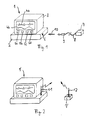
- Fig. 1 depicts a medical monitor generally outlined as 1. The monitor consists of a
box 2 and adisplay 3.Box 2 contains the necessary hardware like preamplifiers and analog signal processing circuits, the digital components, at least one microprocessor and the circuitry necessary to operate this processor, particularly certain memory circuits. The details of the front-end connection, in particular the transducers and their connection tobox 2, are not shown in Fig. 1. -
Display 3 is used to present the results of the various measurements. For the purpose of illustration, an ECG (Electrocardiogram)wave 4a and ablood pressure waveform 4b are depicted in Fig. 1. -
Display 3 further comprises several keys provided for user interaction. Some of these keys are labelled as 5a to 5d in Fig. 1. It is understood that an actual monitor provides more than the four keys shown in Fig. 1. - Operation of
medical monitor 1 is controlled by its internal processor. This processor performs a variety of functions, e.g. wave form filtering and digital signal processing, setting of alarm limits and generating an alarm when such limit is exceeded, lead selection if an ECG is displayed, communication with a recorder or a remote station and so on. -
Medical monitor 1 further comprises a jack 6, the function of which will be explained below. - Due to the multiplicity of program-controlled functions and the large amount and the complexity of the software provided for the operation of the processor or the processors controlling
medical monitor 1, the need arises to change or update the programs contained in the memories ofmedical monitor 1 from time to time. Such may e.g. be the case if software containing a programming error ("bug") is to be exchanged, if new programs necessary to operate a new medical parameter or a new kind of data processing has to be added (or, if already present, has to be activated), or if special tests have to be performed. - Fig. 1 further shows an activating circuit, here in form of a box 7. Box 7 contains a one-chip-microprocessor and the necessary peripheral hardware to control this processor as well as a serial interface. Said interface is connected with a cable 8 which ends in a connector 9.
- Box 7 is preferably used to add additional functionality to the programs contained in
medical monitor 1, i.e. to provide new programs to this monitor. Box 7, cable 8 and connector 9 are separately sold in form of an "update kit" containing these components as well as an instruction sheet. - The customer needs simply to connect box 7 with
medical monitor 1, i.e. to put connector 9 in jack 6 as depicted byarrow 10. The memory provided with the microprocessor contained in box 7 comprises at least two modules, the first establishing a communication withmedical monitor 1 and the second transmitting program code to said monitor. Once the first module has established the communication between the two devices, it transfers control to the second module which downloads the additional program code tomedical monitor 1. The processor ofmonitor 1 is now able to execute the new program code, i.e. to establish the new functions provided by the downloaded programs. - It is understood that box 7 cannot only be used to download new programs, but also to activate programs which were already contained, but "hidden" in the software of
medical monitor 1. Further, instead of adding new functionality, the downloaded programs or activating codes may be used to install or start special test sequences. Last not least, box 7 may also be used to exchange software containing a bug. - The first module contained in box 7 may further comprise certain controlling functions ensuring that box 7 can only be used with one medical monitor. The operation of such controlling sequences will be explained by means of Fig. 6.
- Another environment is depicted in Fig. 2. Medical monitor 1' is equipped with an
antenna 11, and box 7' is also equipped with anotherantenna 12. In this example, communication between the medical monitor and the activating circuit as well as program/code download is performed using wireless transmission with electromagnetic waves. The other components of the medical monitor and the box may be similar as in the environment of Fig. 1. It is understood that wireless transmission may also be performed using infrared light or the like. - Fig. 3 shows a further environment in which the activating circuit comprises a
personal computer 13. The personal computer consists ofcomputer box 14,display 15,keyboard 16 and other common components such as disc drives, a mouse etc. (not shown in Fig. 3). -
Personal computer 13 as well as medical monitor 1'' contain modems. Communication between the two devices is set up from the modem of monitor 1'' to atelephone 17, atelephone connection 18 and asecond telephone 19 to the modem ofpersonal computer 13 and vice versa. - The environment depicted in Fig. 3 is especially suited if a program needs updating, i.e. if a software bug has been detected and the program has to be exchanged with a new revision in which these errors have been corrected. The environment of Fig. 3 allows to load the revised program on a multiplicity of monitors without the need to send a service engineer to every customer in possession of a monitor.
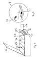
Personal computer 13 is located in the manufacturer's building and may be used to update all monitors already distributed even if they are located in very remote places. - Fig. 4 depicts a hardware box 2'' corresponding to
hardware box 2 ofmedical monitor 1 in Fig. 1. For the purpose of illustration, cover 20 of this box is drawn in its open position. The hardware box contains a multiplicity of printedcircuit boards 21a to 21e. - Detail V of this figure is drawn in larger size in Fig. 5.
Board 21a comprises anintegrated circuit socket 22 which operates as connection means to the medical monitor. The activating circuit consists of a very small one-chip-microprocessor 23 with four pins (one for the supply voltage, one for ground, one for transmission and one for receive operation).Microprocessor 23 is delivered as an option to the medical monitor and is able to transmit program or activating codes according to the principles described herein.Socket 22 is normally hidden behind a small door 2''a. In order to installmicroprocessor 23, door 2''a has to be opened, andmicroprocessor 23 has to be inserted intosocket 22. As box 2'' has not to be opened completely for this purpose, installation can be performed by the customer without the danger of causing electrical malfunction, particularly ifsocket 22 is appropriately isolated. - It is understood that the environment of Figs. 4 and 5 is particularly useful if new functionality is to be added, especially if certain programs are already "hidden" in the monitor and can be activated by an activating code transmitted by
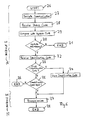
microprocessor 23. - Fig. 6 is a flow chart explaining the basic operating mode of the processor contained in the activating circuit. Two
modules - In step 29, the received status code is compared with the update code contained in the activating circuit, and in step 30 a decision is made whether an update is necessary in the light of the foregoing comparison. For example, if the status code and the update code contain the same date or revision number, this means that the electronic device's memory already contains the program which is to be downloaded, and therefore operation stops (reference number 31).
- If it is decided that the programs in the electronic device need to be updated, operation continues with
step 32, i.e. the activating circuit receives an identification code from the electronic device. The identification code is a code unique for each electronic device, for example its serial number. - A decision is then made (step 33) whether this is the first identification code ever received by the activating circuit. If the answer is "yes", then this identification code is stored (step 34). If the answer is "no", the processor in the activating circuit checks whether the received identification code and the stored identification code are equal (step 35). In case they are not equal, this means that the activating circuit has already been used in conjunction with another electronic device and therefore cannot be used together with the present one. In this case, operation stops (step 36).
- It has to be emphasized that usually, if the identification codes are equal, this means that the electronic device has already received the new programs and that therefore, as the status code and the update code comply with each other, operation stops already at
step 31. However, it may happen that a defective memory in the electronic device has been exchanged and that therefore a new download procedure may be necessary. - In case the activating circuit has received the first identification code or in case that the identification codes are equal, control is transferred to module II which handles the transmission and data exchange between the activating circuit and the electronic device (step 37). This transmission is performed in known manner, i.e. using a handshake procedure. When all program, test or activating codes have been transferred to the electronic device, operation stops (step 38).
Claims (13)
- Activating circuit (7,7',13,23) for an electronic device (1,1',1",2"), said electronic device (1,1',1",2") containing a processor and a memory and operating at least partially under program control and, said activating circuit (7,7',13,23) comprises:(1.1) a processor,(1.2) a nonvolatile, erasable memory,(1.3) connections means (10,11,12,17-19,22) for connecting said activating circuit (7,7',13,23) with said electronic device (1,1',1",2"),(1.4) a program stored in said nonvolatile, erasable memory, said program containing:characterized in that(1.4.1) a first module (24) setting up a communication with said electronic device (1,1',1",2"),(1.4.2) a second module (25) set up to transmit data and/or code to said electronic device (1,1',1",2").(1.5) said first module (24) is set up to receive an identification code (32) from said electronic device (1,1',1",2"),(1.6) said first module (24) is set up to store said identification code (34) in said nonvolatile, erasable memory the first time it receives such identification code, and(1.7) said first module (24) is further set up to accept only the stored identification code and to prevent said second module (25) from transmitting data and/or code to said electronic device if the identification codes are not equal.
- Activating circuit (7,7',13,23) for an electronic device (1,1',1",2"), said electronic device (1,1',1",2") containing a processor and a memory and operating at least partially under program control, said activating circuit (7,7',13,23) comprising:(2.1) a processor,(2.2) a nonvolatile, erasable memory,(2.3) connections means (10,11,12,17-19,22) for connecting said activating circuit (7,7',13,23) with said electronic device (1,1',1",2"),(2.4) a program stored in said nonvolatile, erasable memory, said program containing:characterized in that(2.4.1) a first module (24) setting up a communication with said electronic device (1,1',1",2"),(2.4.2) a second module (25) set up to transmit data and/or code to said electronic device (1,1',1",2").(2.5) said first module (24) is set up to receive an identification code (32) from said electronic device (1,1',1",2"),(2.6) said first module (24) is set up to store said identification code (34) in said nonvolatile, erasable memory the first time it receives such identification code,(2.7) said second module (25) is set up to encode the transmitted data and/or code in dependency of the identification code stored by said first module (24) in said nonvolatile, erasable memory.
- Activating circuit according to claim 1 or 2, characterized in that said second module is set up to transmit program code to said electronic device (1,1',1",2").
- Activating circuit according to claim 1 or 2, characterized in that said second module is set up to transmit an activating code to said electronic device (1,1',1",2").
- Activating circuit according to claim 1 or 2, characterized in that said second module is set up to transmit a test code or program to said electronic device (1,1',1",2").
- Activating circuit according to at least one of claims 1 to 5, characterized in that said first module (24) is set up to receive a status code (28) from said electronic device (1,1',1",2"), to compare said status code with a stored update code (30) and to transfer control to said second module (25) only if said status code is in a predefined relation to said update code.
- Activating circuit according to claim 6, characterized in that said first module (24) transfers control to said second module (25) only when said status code indicates a lower revision number or an earlier date than said update code.
- Activating circuit according to at least one of the preceding claims, characterized in that said activating circuit (7,7') is contained in a housing and that said connection means comprises a cable (8).
- Activating circuit according to claim 8, characterized in that said activating circuit (7,7') comprises a microprocessor, preferably of the 1-chip type with integrated nonvolatile, erasable memory.
- Activating circuit according to at least one of claims 1-7, characterized in that said activating circuit comprises a computer (13), preferably a personal computer, and that said connection means comprises a telephone or a wireless transmitter.
- Activating circuit according to at least one of claims 1-7, characterized in that said activating device comprises an integrated microprocessor (23) and that said connection means comprises a multiplicity of pins of said integrated microprocessor (23) for insertion in a socket (22) in said electronic device (2").
- Method for activating or adding new capabilities to an electronic device (1,1',1",2") operating at least partially under program control, wherein an activating circuit (7,7',13,23) is connected with the electronic device (1,1',1",2") and said activating circuit (7,7',13,23) sets up a communication with and transmits data and/or code to said electronic device (1,1',1'',2''), characterized in that said activating circuit (7,7',13,23) receives an identification code from the electronic device (1,1',1",2") and(12.1) stores said received identification code in an erasable memory the first time it receives such identification code,(12.2) otherwise compares the received identification code with the stored identification code and transmits data and/or code only if said identification codes are equal.
- Method according to claim 12, characterized in that said activating circuit (7,7',13,23) receives a status code from said electronic device (1,1',1",2") and transmits data and/or code only if said status code indicates a lower revision number or an earlier date than an update code stored in said activating circuit (7,7',13,23).
Priority Applications (4)
| Application Number | Priority Date | Filing Date | Title |
|---|---|---|---|
| DE69024638T DE69024638T2 (en) | 1990-05-21 | 1990-05-21 | Activation circuit |
| EP90109653A EP0457940B1 (en) | 1990-05-21 | 1990-05-21 | Activating circuit |
| US07/668,086 US5371692A (en) | 1990-05-21 | 1991-03-12 | Activating circuit for modifying or adding a new program to an electronic device |
| JP14568091A JPH0689169A (en) | 1990-05-21 | 1991-05-21 | Activating circuit and method for activating or adding new capability |
Applications Claiming Priority (1)
| Application Number | Priority Date | Filing Date | Title |
|---|---|---|---|
| EP90109653A EP0457940B1 (en) | 1990-05-21 | 1990-05-21 | Activating circuit |
Publications (2)
| Publication Number | Publication Date |
|---|---|
| EP0457940A1 true EP0457940A1 (en) | 1991-11-27 |
| EP0457940B1 EP0457940B1 (en) | 1996-01-03 |
Family
ID=8204012
Family Applications (1)
| Application Number | Title | Priority Date | Filing Date |
|---|---|---|---|
| EP90109653A Expired - Lifetime EP0457940B1 (en) | 1990-05-21 | 1990-05-21 | Activating circuit |
Country Status (4)
| Country | Link |
|---|---|
| US (1) | US5371692A (en) |
| EP (1) | EP0457940B1 (en) |
| JP (1) | JPH0689169A (en) |
| DE (1) | DE69024638T2 (en) |
Cited By (18)
| Publication number | Priority date | Publication date | Assignee | Title |
|---|---|---|---|---|
| FR2693007A1 (en) * | 1992-06-26 | 1993-12-31 | Ela Medical Sa | Method for automatically installing a microprocessor system and corresponding system |
| EP0618531A1 (en) * | 1993-03-31 | 1994-10-05 | Siemens Aktiengesellschaft | Method and arrangement for loading and reloading control programs of a processor |
| WO1995021411A1 (en) * | 1994-02-07 | 1995-08-10 | Euro Cp S.A.R.L. | Electronic structure comprising a multi-application component; methods and coding key for its implementation |
| EP0762335A2 (en) * | 1995-09-08 | 1997-03-12 | Francotyp-Postalia Aktiengesellschaft & Co. | Method for changing data charged in memory cells of an electronic franking machine |
| GB2310298A (en) * | 1996-02-15 | 1997-08-20 | Motorola Israel Ltd | Updating operating systems of remote computers by radio link |
| EP0809201A2 (en) * | 1996-05-22 | 1997-11-26 | Fujitsu Limited | Information processing system and recording media |
| WO1998040812A1 (en) * | 1997-03-13 | 1998-09-17 | Gemplus S.C.A. | Method for monitoring the secure segmentation of applications loaded in a multi-application terminal and terminal implementing same |
| EP0905590A2 (en) * | 1997-09-25 | 1999-03-31 | Matsushita Electric Industrial Co., Ltd. | Controlled device, controller, information control center, initialization-allowing communication system, and communication control system and medium |
| WO1999045458A2 (en) * | 1998-03-04 | 1999-09-10 | BODENSEEWERK GERäTETECHNIK GMBH | Method and device for reading programmes into a processor-controlled device |
| WO1999045455A1 (en) * | 1998-03-06 | 1999-09-10 | Tv Objects Limited, L.L.C. | Data and access protection system for computers |
| EP1001321A2 (en) * | 1998-10-24 | 2000-05-17 | E.G.O. Elektro-Gerätebau GmbH | Control of an electrical device |
| EP1006420A1 (en) * | 1998-12-02 | 2000-06-07 | BOTTERO S.p.A. | Glassware molding machine with a machine operating data access level identification system |
| GB2344445A (en) * | 1998-12-04 | 2000-06-07 | Pittway Corp | Communication |
| WO2001034222A2 (en) | 1999-11-09 | 2001-05-17 | Fresenius Medical Care Deutschland Gmbh | Software update for a medical fluid management device |
| EP1336378A1 (en) * | 2000-11-01 | 2003-08-20 | Kabushiki Kaisha Toshiba | Ultrasonic diagnostic device, method for expanding function on ultrasonic diagnosis, and method for providing expanded function on ultrasonic diagnosis |
| GB2412983A (en) * | 2004-04-07 | 2005-10-12 | Siemens Med Solutions Health | A system for managing the usage of a device |
| FR2878043A1 (en) * | 2004-11-12 | 2006-05-19 | Briot Internat Sa | Information e.g. mounts and optical glass size templates catalogue information, loading system for automated machine, has module to store information to be loaded in machine, where module and machine include complementary connection units |
| EP1818819A1 (en) | 2006-01-17 | 2007-08-15 | B. Braun Medizintechnologie GmbH | Method for organising the software of a fluid management system |
Families Citing this family (58)
| Publication number | Priority date | Publication date | Assignee | Title |
|---|---|---|---|---|
| US5841991A (en) * | 1992-11-18 | 1998-11-24 | Canon Information Systems, Inc. | In an Interactive network board, a method and apparatus for storing a media access control address in a remotely alterable memory |
| US5483658A (en) * | 1993-02-26 | 1996-01-09 | Grube; Gary W. | Detection of unauthorized use of software applications in processing devices |
| US5625690A (en) * | 1993-11-15 | 1997-04-29 | Lucent Technologies Inc. | Software pay per use system |
| US5802274A (en) * | 1994-05-04 | 1998-09-01 | International Business Machines Corporation | Cartridge manufacturing system for game programs |
| FR2727219B1 (en) * | 1994-11-18 | 1997-01-10 | Hutchinson | TIMER, MACHINE COMPRISING SUCH TIMER AND METHOD OF USING SAME |
| US6529590B1 (en) * | 1994-11-23 | 2003-03-04 | Coltec Industries, Inc. | Systems and methods for remotely controlling a machine |
| IT1271796B (en) * | 1994-12-23 | 1997-06-09 | Lomar S R L | CONTROL EQUIPMENT OF AT LEAST ONE ACTUATOR OPERATIVELY CONNECTED TO A FLEXIBLE PROGRAMMING STATION |
| US5619250A (en) * | 1995-02-19 | 1997-04-08 | Microware Systems Corporation | Operating system for interactive television system set top box utilizing dynamic system upgrades |
| US5699275A (en) * | 1995-04-12 | 1997-12-16 | Highwaymaster Communications, Inc. | System and method for remote patching of operating code located in a mobile unit |
| US6671563B1 (en) * | 1995-05-15 | 2003-12-30 | Alaris Medical Systems, Inc. | System and method for collecting data and managing patient care |
| US5996004A (en) * | 1996-01-02 | 1999-11-30 | Bp Microsystems, Inc. | Concurrent programming apparatus and method for electronic devices |
| US5603323A (en) * | 1996-02-27 | 1997-02-18 | Advanced Technology Laboratories, Inc. | Medical ultrasonic diagnostic system with upgradeable transducer probes and other features |
| US5892902A (en) * | 1996-09-05 | 1999-04-06 | Clark; Paul C. | Intelligent token protected system with network authentication |
| US6173400B1 (en) * | 1998-07-31 | 2001-01-09 | Sun Microsystems, Inc. | Methods and systems for establishing a shared secret using an authentication token |
| US6554798B1 (en) † | 1998-08-18 | 2003-04-29 | Medtronic Minimed, Inc. | External infusion device with remote programming, bolus estimator and/or vibration alarm capabilities |
| US6141584A (en) | 1998-09-30 | 2000-10-31 | Agilent Technologies, Inc. | Defibrillator with wireless communications |
| US6546360B1 (en) * | 1998-10-30 | 2003-04-08 | Trimble Navigation Limited | Device servicing system and method |
| US7096282B1 (en) * | 1999-07-30 | 2006-08-22 | Smiths Medical Pm, Inc. | Memory option card having predetermined number of activation/deactivation codes for selectively activating and deactivating option functions for a medical device |
| US20030095648A1 (en) * | 1999-10-05 | 2003-05-22 | Lifecor, Inc. | Fault-tolerant remote reprogramming for a patient-worn medical device |
| US6442433B1 (en) * | 1999-10-26 | 2002-08-27 | Medtronic, Inc. | Apparatus and method for remote troubleshooting, maintenance and upgrade of implantable device systems |
| US6327501B1 (en) | 1999-11-02 | 2001-12-04 | Pacesetter, Inc. | System and method for determining safety alert conditions for implantable medical devices |
| US7060031B2 (en) * | 1999-12-17 | 2006-06-13 | Medtronic, Inc. | Method and apparatus for remotely programming implantable medical devices |
| US20060189854A1 (en) * | 1999-12-17 | 2006-08-24 | Medtronic, Inc. | Method and apparatus for remotely programming implantable medical devices |
| US7860583B2 (en) | 2004-08-25 | 2010-12-28 | Carefusion 303, Inc. | System and method for dynamically adjusting patient therapy |
| NZ522631A (en) | 2000-05-18 | 2004-07-30 | Alaris Medical Inc | Distributed remote asset and medication management drug delivery system |
| US9069887B2 (en) | 2000-05-18 | 2015-06-30 | Carefusion 303, Inc. | Patient-specific medication management system |
| US10353856B2 (en) | 2011-03-17 | 2019-07-16 | Carefusion 303, Inc. | Scalable communication system |
| US10062457B2 (en) | 2012-07-26 | 2018-08-28 | Carefusion 303, Inc. | Predictive notifications for adverse patient events |
| US9741001B2 (en) | 2000-05-18 | 2017-08-22 | Carefusion 303, Inc. | Predictive medication safety |
| US9427520B2 (en) | 2005-02-11 | 2016-08-30 | Carefusion 303, Inc. | Management of pending medication orders |
| US11087873B2 (en) | 2000-05-18 | 2021-08-10 | Carefusion 303, Inc. | Context-aware healthcare notification system |
| US6782345B1 (en) * | 2000-10-03 | 2004-08-24 | Xerox Corporation | Systems and methods for diagnosing electronic systems |
| US7243853B1 (en) * | 2001-12-04 | 2007-07-17 | Visa U.S.A. Inc. | Method and system for facilitating memory and application management on a secured token |
| US7810729B2 (en) * | 2009-06-10 | 2010-10-12 | Rem Holdings 3, Llc | Card reader device for a cell phone and method of use |
| US6785820B1 (en) * | 2002-04-02 | 2004-08-31 | Networks Associates Technology, Inc. | System, method and computer program product for conditionally updating a security program |
| DE10240584A1 (en) | 2002-08-28 | 2004-03-11 | Pilz Gmbh & Co. | Safety control system for fault protected operation of critical process such as occurs in machine system operation |
| US20040139021A1 (en) | 2002-10-07 | 2004-07-15 | Visa International Service Association | Method and system for facilitating data access and management on a secure token |
| DE10251523A1 (en) * | 2002-11-04 | 2004-05-19 | Siemens Ag | System and method for providing data and services for devices, and device that uses the data and services provided |
| JP5255770B2 (en) | 2003-12-05 | 2013-08-07 | ケアフュージョン 303、インコーポレイテッド | System and method for network monitoring of multiple medical devices |
| EP1947535A1 (en) * | 2007-01-17 | 2008-07-23 | Siemens Aktiengesellschaft | Monitoring the programming of an automation device |
| US8369944B2 (en) | 2007-06-06 | 2013-02-05 | Zoll Medical Corporation | Wearable defibrillator with audio input/output |
| EP2396756A4 (en) | 2009-02-10 | 2012-07-25 | 4361423 Canada Inc | Apparatus and method for commercial transactions using a communication device |
| US7896248B2 (en) | 2009-06-10 | 2011-03-01 | Rem Holdings 3, Llc | Card reader device and method of use |
| US20110078596A1 (en) * | 2009-09-30 | 2011-03-31 | Nellcor Puritan Bennett Llc | Protocol Analyzer System And Method For Medical Monitoring Module |
| US8489167B2 (en) * | 2009-09-30 | 2013-07-16 | Covidien Lp | Evaluation kit for medical monitoring module system and method |
| US8565847B2 (en) * | 2009-09-30 | 2013-10-22 | Covidien Lp | Evaluation board for a medical monitoring module system and method |
| WO2012135062A1 (en) | 2011-03-25 | 2012-10-04 | Zoll Medical Corporation | Selection of optimal channel for rate determination |
| US8600486B2 (en) | 2011-03-25 | 2013-12-03 | Zoll Medical Corporation | Method of detecting signal clipping in a wearable ambulatory medical device |
| US10430554B2 (en) | 2013-05-23 | 2019-10-01 | Carefusion 303, Inc. | Medication preparation queue |
| US11182728B2 (en) | 2013-01-30 | 2021-11-23 | Carefusion 303, Inc. | Medication workflow management |
| BR112015019758B1 (en) | 2013-03-13 | 2022-07-05 | Carefusion 303, Inc | SYSTEM AND METHOD FOR USE WITH MEDICAL DEVICE TO REDUCE MEDICATION ERRORS AND MACHINE-READABLE STORAGE MEDIA |
| EP4195119A1 (en) | 2013-03-13 | 2023-06-14 | Carefusion 303 Inc. | Predictive medication safety |
| US10272010B2 (en) | 2015-03-20 | 2019-04-30 | Zoll Medical Corporation | Systems and methods for testing a medical device |
| US11709747B2 (en) | 2016-01-08 | 2023-07-25 | Zoll Medical Corporation | Patient assurance system and method |
| US20170277517A1 (en) * | 2016-03-22 | 2017-09-28 | M2Communication Inc. | Method Of Updating Program Code And Electronic Device Using The Same |
| US10674911B2 (en) | 2016-03-30 | 2020-06-09 | Zoll Medical Corporation | Systems and methods of integrating ambulatory medical devices |
| US10426342B2 (en) | 2016-03-31 | 2019-10-01 | Zoll Medical Corporation | Remote access for ambulatory medical device |
| US11213691B2 (en) | 2017-02-27 | 2022-01-04 | Zoll Medical Corporation | Ambulatory medical device interaction |
Citations (5)
| Publication number | Priority date | Publication date | Assignee | Title |
|---|---|---|---|---|
| US3984637A (en) * | 1974-11-29 | 1976-10-05 | The Singer Company | Computer terminal security system |
| DE3417143A1 (en) * | 1983-05-09 | 1984-11-15 | Romox Inc | DEVICE AND METHOD FOR PROGRAMMING MEMORY CASSETTES |
| WO1985002310A1 (en) * | 1983-11-14 | 1985-05-23 | Softnet, Incorporated | Software distribution system |
| EP0217351A2 (en) * | 1985-09-30 | 1987-04-08 | Kabushiki Kaisha Toshiba | Communication control apparatus |
| EP0338290A2 (en) * | 1988-04-20 | 1989-10-25 | Siemens Aktiengesellschaft | Method for loading an operating command sequence necessary for operating a microprocessor-controlled electrical device |
Family Cites Families (8)
| Publication number | Priority date | Publication date | Assignee | Title |
|---|---|---|---|---|
| US4353064A (en) * | 1981-01-14 | 1982-10-05 | Honeywell Inc. | Battery operated access control card |
| US4573046A (en) * | 1983-11-01 | 1986-02-25 | Universal Photonics, Inc. | Watch apparatus and method for a universal electronic locking system |
| US4829296A (en) * | 1986-04-30 | 1989-05-09 | Carey S. Clark | Electronic lock system |
| FR2606530A1 (en) * | 1986-11-07 | 1988-05-13 | Eurotechnique Sa | INTEGRATED CIRCUIT FOR MEMORIZING AND PROCESSING CONFIDENTIALLY INFORMATION WITH AN ANTI-FRAUD DEVICE |
| US5109221A (en) * | 1987-05-21 | 1992-04-28 | Trw Inc. | Remote control system for door locks |
| US4839628A (en) * | 1988-01-11 | 1989-06-13 | Motorola, Inc. | Paging receiver having selectively protected regions of memory |
| US5012234A (en) * | 1989-05-04 | 1991-04-30 | Motorola, Inc. | User activated memory programming authorization in a selective call receiver |
| US5099516A (en) * | 1989-06-12 | 1992-03-24 | Dell Corporate Services Corporation | Digital computer code word identification system |
-
1990
- 1990-05-21 DE DE69024638T patent/DE69024638T2/en not_active Expired - Fee Related
- 1990-05-21 EP EP90109653A patent/EP0457940B1/en not_active Expired - Lifetime
-
1991
- 1991-03-12 US US07/668,086 patent/US5371692A/en not_active Expired - Fee Related
- 1991-05-21 JP JP14568091A patent/JPH0689169A/en active Pending
Patent Citations (5)
| Publication number | Priority date | Publication date | Assignee | Title |
|---|---|---|---|---|
| US3984637A (en) * | 1974-11-29 | 1976-10-05 | The Singer Company | Computer terminal security system |
| DE3417143A1 (en) * | 1983-05-09 | 1984-11-15 | Romox Inc | DEVICE AND METHOD FOR PROGRAMMING MEMORY CASSETTES |
| WO1985002310A1 (en) * | 1983-11-14 | 1985-05-23 | Softnet, Incorporated | Software distribution system |
| EP0217351A2 (en) * | 1985-09-30 | 1987-04-08 | Kabushiki Kaisha Toshiba | Communication control apparatus |
| EP0338290A2 (en) * | 1988-04-20 | 1989-10-25 | Siemens Aktiengesellschaft | Method for loading an operating command sequence necessary for operating a microprocessor-controlled electrical device |
Cited By (34)
| Publication number | Priority date | Publication date | Assignee | Title |
|---|---|---|---|---|
| EP0578530A1 (en) * | 1992-06-26 | 1994-01-12 | Ela Medical | Method for automatic initialisation of a microprocessor system and corresponding system |
| FR2693007A1 (en) * | 1992-06-26 | 1993-12-31 | Ela Medical Sa | Method for automatically installing a microprocessor system and corresponding system |
| EP0618531A1 (en) * | 1993-03-31 | 1994-10-05 | Siemens Aktiengesellschaft | Method and arrangement for loading and reloading control programs of a processor |
| WO1995021411A1 (en) * | 1994-02-07 | 1995-08-10 | Euro Cp S.A.R.L. | Electronic structure comprising a multi-application component; methods and coding key for its implementation |
| FR2716017A1 (en) * | 1994-02-07 | 1995-08-11 | Euro Cp Sarl | Multi-application electronic structure, and methods for its implementation. |
| EP0762335A3 (en) * | 1995-09-08 | 2000-01-12 | Francotyp-Postalia Aktiengesellschaft & Co. | Method for changing data charged in memory cells of an electronic franking machine |
| EP0762335A2 (en) * | 1995-09-08 | 1997-03-12 | Francotyp-Postalia Aktiengesellschaft & Co. | Method for changing data charged in memory cells of an electronic franking machine |
| GB2310298A (en) * | 1996-02-15 | 1997-08-20 | Motorola Israel Ltd | Updating operating systems of remote computers by radio link |
| EP0809201A3 (en) * | 1996-05-22 | 2000-05-03 | Fujitsu Limited | Information processing system and recording media |
| US6317878B1 (en) | 1996-05-22 | 2001-11-13 | Fujitsu Limited | Information processing system and recording media |
| EP0809201A2 (en) * | 1996-05-22 | 1997-11-26 | Fujitsu Limited | Information processing system and recording media |
| FR2760865A1 (en) * | 1997-03-13 | 1998-09-18 | Gemplus Card Int | METHOD FOR CONTROLLING THE SEALING OF APPLICATIONS CHARGED IN A MULTI-APPLICATION TERMINAL AND TERMINAL FOR THE IMPLEMENTATION |
| WO1998040812A1 (en) * | 1997-03-13 | 1998-09-17 | Gemplus S.C.A. | Method for monitoring the secure segmentation of applications loaded in a multi-application terminal and terminal implementing same |
| EP0905590A2 (en) * | 1997-09-25 | 1999-03-31 | Matsushita Electric Industrial Co., Ltd. | Controlled device, controller, information control center, initialization-allowing communication system, and communication control system and medium |
| US7043571B2 (en) | 1997-09-25 | 2006-05-09 | Matsushita Electric Industrial Co., Ltd. | Controlled device, controller, information control center, initialization-allowing communication system, and communication control system and medium |
| US6584364B1 (en) | 1997-09-25 | 2003-06-24 | Matsushita Electric Industrial Co., Ltd. | Controlled device, controller, information control center, initialization-allowing communication system, and communication control system and medium |
| EP0905590A3 (en) * | 1997-09-25 | 2000-12-13 | Matsushita Electric Industrial Co., Ltd. | Controlled device, controller, information control center, initialization-allowing communication system, and communication control system and medium |
| WO1999045458A2 (en) * | 1998-03-04 | 1999-09-10 | BODENSEEWERK GERäTETECHNIK GMBH | Method and device for reading programmes into a processor-controlled device |
| WO1999045458A3 (en) * | 1998-03-04 | 1999-11-11 | Bodenseewerk Geraetetech | Method and device for reading programmes into a processor-controlled device |
| WO1999045455A1 (en) * | 1998-03-06 | 1999-09-10 | Tv Objects Limited, L.L.C. | Data and access protection system for computers |
| EP1001321A2 (en) * | 1998-10-24 | 2000-05-17 | E.G.O. Elektro-Gerätebau GmbH | Control of an electrical device |
| EP1001321A3 (en) * | 1998-10-24 | 2003-05-14 | E.G.O. Elektro-Gerätebau GmbH | Control of an electrical device |
| EP1006420A1 (en) * | 1998-12-02 | 2000-06-07 | BOTTERO S.p.A. | Glassware molding machine with a machine operating data access level identification system |
| US6366215B1 (en) | 1998-12-04 | 2002-04-02 | Pittway Corporation | Communications systems and methods |
| GB2344445B (en) * | 1998-12-04 | 2002-06-19 | Pittway Corp | Communications systems and methods |
| GB2344445A (en) * | 1998-12-04 | 2000-06-07 | Pittway Corp | Communication |
| WO2001034222A2 (en) | 1999-11-09 | 2001-05-17 | Fresenius Medical Care Deutschland Gmbh | Software update for a medical fluid management device |
| EP1336378A4 (en) * | 2000-11-01 | 2004-12-01 | Toshiba Kk | Ultrasonic diagnostic device, method for expanding function on ultrasonic diagnosis, and method for providing expanded function on ultrasonic diagnosis |
| EP1336378A1 (en) * | 2000-11-01 | 2003-08-20 | Kabushiki Kaisha Toshiba | Ultrasonic diagnostic device, method for expanding function on ultrasonic diagnosis, and method for providing expanded function on ultrasonic diagnosis |
| US7060032B2 (en) | 2000-11-01 | 2006-06-13 | Kabushiki Kaisha Toshiba | Ultrasonic diagnostic device, function extending method related to ultrasonic diagnosis, and method of providing extension function related to ultrasonic diagnosis |
| GB2412983A (en) * | 2004-04-07 | 2005-10-12 | Siemens Med Solutions Health | A system for managing the usage of a device |
| FR2878043A1 (en) * | 2004-11-12 | 2006-05-19 | Briot Internat Sa | Information e.g. mounts and optical glass size templates catalogue information, loading system for automated machine, has module to store information to be loaded in machine, where module and machine include complementary connection units |
| EP1818819A1 (en) | 2006-01-17 | 2007-08-15 | B. Braun Medizintechnologie GmbH | Method for organising the software of a fluid management system |
| US8219982B2 (en) | 2006-01-17 | 2012-07-10 | B. Braun Medizintechnologie Gmbh | Method for organizing the software of a fluid management system |
Also Published As
| Publication number | Publication date |
|---|---|
| EP0457940B1 (en) | 1996-01-03 |
| JPH0689169A (en) | 1994-03-29 |
| US5371692A (en) | 1994-12-06 |
| DE69024638D1 (en) | 1996-02-15 |
| DE69024638T2 (en) | 1996-05-15 |
Similar Documents
| Publication | Publication Date | Title |
|---|---|---|
| EP0457940B1 (en) | Activating circuit | |
| US5918194A (en) | Integrated modular measurement system having configurable firmware architecture and modular mechanical parts | |
| US5357519A (en) | Diagnostic system | |
| US6892216B2 (en) | Common platform for use in automotive services | |
| US5821405A (en) | Modular water quality apparatus and method | |
| US20080098380A1 (en) | System, method, and device for updating programmable electronic equipment with a transport device from a deployment server via the internet or other communication medium | |
| JPS61188638A (en) | Apparatus and method for testing electronic system | |
| JPS6335228A (en) | System for operating detachable ram package for medical monitor of outpatient | |
| US6931525B2 (en) | Method for switching between boot devices in information processing unit | |
| US5557741A (en) | Test apparatus and method for a computer parallel port | |
| US5588114A (en) | Method and apparatus for passive loopback testing of software-controllable parallel ports | |
| JP2011258219A (en) | Computing device | |
| WO1996002034A1 (en) | Updating firmware | |
| US6904484B1 (en) | Low pin count (LPC) firmware hub recovery | |
| US6499122B1 (en) | Adjustable voltage boundary scan adapter for emulation and test | |
| US6094720A (en) | Computer system having automatic power on and initialization for in-box configuration | |
| JPH0673122B2 (en) | Programmable connector device | |
| US7801714B2 (en) | Flight simulator adapted for a family of aircraft | |
| US5845114A (en) | PC card initialization for microprocessor based devices | |
| EP0785508A2 (en) | Method of controlling data writing into on-board microcomputer | |
| KR940002477B1 (en) | Versatile control system utilizing a microcontroller | |
| US6832339B1 (en) | Methods and apparatus for programming a solid-state meter | |
| EP1285280B1 (en) | Solid-state single-phase meter and methods and apparatus for programming such meter | |
| CN111367538A (en) | Electronic device for updating on-board data without starting up | |
| KR100235632B1 (en) | Rom bios data correction method |
Legal Events
| Date | Code | Title | Description |
|---|---|---|---|
| PUAI | Public reference made under article 153(3) epc to a published international application that has entered the european phase |
Free format text: ORIGINAL CODE: 0009012 |
|
| 17P | Request for examination filed |
Effective date: 19901224 |
|
| AK | Designated contracting states |
Kind code of ref document: A1 Designated state(s): BE DE DK FR GB IT NL SE |
|
| 17Q | First examination report despatched |
Effective date: 19940811 |
|
| GRAA | (expected) grant |
Free format text: ORIGINAL CODE: 0009210 |
|
| RIN1 | Information on inventor provided before grant (corrected) |
Inventor name: DRAEGER, JUERGEN Inventor name: PARET, GUENTER |
|
| AK | Designated contracting states |
Kind code of ref document: B1 Designated state(s): BE DE DK FR GB IT NL SE |
|
| PG25 | Lapsed in a contracting state [announced via postgrant information from national office to epo] |
Ref country code: IT Free format text: LAPSE BECAUSE OF FAILURE TO SUBMIT A TRANSLATION OF THE DESCRIPTION OR TO PAY THE FEE WITHIN THE PRESCRIBED TIME-LIMIT;WARNING: LAPSES OF ITALIAN PATENTS WITH EFFECTIVE DATE BEFORE 2007 MAY HAVE OCCURRED AT ANY TIME BEFORE 2007. THE CORRECT EFFECTIVE DATE MAY BE DIFFERENT FROM THE ONE RECORDED. Effective date: 19960103 Ref country code: NL Free format text: LAPSE BECAUSE OF FAILURE TO SUBMIT A TRANSLATION OF THE DESCRIPTION OR TO PAY THE FEE WITHIN THE PRESCRIBED TIME-LIMIT Effective date: 19960103 Ref country code: DK Effective date: 19960103 Ref country code: BE Effective date: 19960103 |
|
| REF | Corresponds to: |
Ref document number: 69024638 Country of ref document: DE Date of ref document: 19960215 |
|
| ET | Fr: translation filed | ||
| PG25 | Lapsed in a contracting state [announced via postgrant information from national office to epo] |
Ref country code: SE Effective date: 19960403 |
|
| NLV1 | Nl: lapsed or annulled due to failure to fulfill the requirements of art. 29p and 29m of the patents act | ||
| PLBE | No opposition filed within time limit |
Free format text: ORIGINAL CODE: 0009261 |
|
| STAA | Information on the status of an ep patent application or granted ep patent |
Free format text: STATUS: NO OPPOSITION FILED WITHIN TIME LIMIT |
|
| 26N | No opposition filed | ||
| PGFP | Annual fee paid to national office [announced via postgrant information from national office to epo] |
Ref country code: FR Payment date: 19980420 Year of fee payment: 9 |
|
| PGFP | Annual fee paid to national office [announced via postgrant information from national office to epo] |
Ref country code: DE Payment date: 19980421 Year of fee payment: 9 |
|
| PGFP | Annual fee paid to national office [announced via postgrant information from national office to epo] |
Ref country code: GB Payment date: 19980427 Year of fee payment: 9 |
|
| PG25 | Lapsed in a contracting state [announced via postgrant information from national office to epo] |
Ref country code: GB Free format text: LAPSE BECAUSE OF NON-PAYMENT OF DUE FEES Effective date: 19990521 |
|
| GBPC | Gb: european patent ceased through non-payment of renewal fee |
Effective date: 19990521 |
|
| PG25 | Lapsed in a contracting state [announced via postgrant information from national office to epo] |
Ref country code: FR Free format text: LAPSE BECAUSE OF NON-PAYMENT OF DUE FEES Effective date: 20000131 |
|
| PG25 | Lapsed in a contracting state [announced via postgrant information from national office to epo] |
Ref country code: DE Free format text: LAPSE BECAUSE OF NON-PAYMENT OF DUE FEES Effective date: 20000301 |
|
| REG | Reference to a national code |
Ref country code: FR Ref legal event code: ST |