EP0458513B1 - LCD touch screen - Google Patents
LCD touch screen Download PDFInfo
- Publication number
- EP0458513B1 EP0458513B1 EP91304329A EP91304329A EP0458513B1 EP 0458513 B1 EP0458513 B1 EP 0458513B1 EP 91304329 A EP91304329 A EP 91304329A EP 91304329 A EP91304329 A EP 91304329A EP 0458513 B1 EP0458513 B1 EP 0458513B1
- Authority
- EP
- European Patent Office
- Prior art keywords
- light
- touch screen
- detecting means
- light detecting
- viewing surface
- Prior art date
- Legal status (The legal status is an assumption and is not a legal conclusion. Google has not performed a legal analysis and makes no representation as to the accuracy of the status listed.)
- Expired - Lifetime
Links
Images
Classifications
-
- G—PHYSICS
- G06—COMPUTING; CALCULATING OR COUNTING
- G06F—ELECTRIC DIGITAL DATA PROCESSING
- G06F3/00—Input arrangements for transferring data to be processed into a form capable of being handled by the computer; Output arrangements for transferring data from processing unit to output unit, e.g. interface arrangements
- G06F3/01—Input arrangements or combined input and output arrangements for interaction between user and computer
- G06F3/03—Arrangements for converting the position or the displacement of a member into a coded form
- G06F3/041—Digitisers, e.g. for touch screens or touch pads, characterised by the transducing means
- G06F3/042—Digitisers, e.g. for touch screens or touch pads, characterised by the transducing means by opto-electronic means
- G06F3/0421—Digitisers, e.g. for touch screens or touch pads, characterised by the transducing means by opto-electronic means by interrupting or reflecting a light beam, e.g. optical touch-screen
-
- G—PHYSICS
- G02—OPTICS
- G02F—OPTICAL DEVICES OR ARRANGEMENTS FOR THE CONTROL OF LIGHT BY MODIFICATION OF THE OPTICAL PROPERTIES OF THE MEDIA OF THE ELEMENTS INVOLVED THEREIN; NON-LINEAR OPTICS; FREQUENCY-CHANGING OF LIGHT; OPTICAL LOGIC ELEMENTS; OPTICAL ANALOGUE/DIGITAL CONVERTERS
- G02F1/00—Devices or arrangements for the control of the intensity, colour, phase, polarisation or direction of light arriving from an independent light source, e.g. switching, gating or modulating; Non-linear optics
- G02F1/01—Devices or arrangements for the control of the intensity, colour, phase, polarisation or direction of light arriving from an independent light source, e.g. switching, gating or modulating; Non-linear optics for the control of the intensity, phase, polarisation or colour
- G02F1/13—Devices or arrangements for the control of the intensity, colour, phase, polarisation or direction of light arriving from an independent light source, e.g. switching, gating or modulating; Non-linear optics for the control of the intensity, phase, polarisation or colour based on liquid crystals, e.g. single liquid crystal display cells
- G02F1/133—Constructional arrangements; Operation of liquid crystal cells; Circuit arrangements
- G02F1/1333—Constructional arrangements; Manufacturing methods
- G02F1/13338—Input devices, e.g. touch panels
Definitions
- This invention relates to optically-based touch sensitive screens, and more particularly to such screens for use with liquid crystal displays (LCDs).
- LCDs liquid crystal displays
- Touch sensitive screens are devices that typically mount over a display such as a CRT. With a touch screen, a user can select from options displayed on the display's viewing surface by touching the surface adjacent to the desired option, or, in some designs, touching the option directly. Common techniques employed in these devices for detecting the location of a touch include mechanical buttons, crossed beams of infrared light, acoustic surface waves, capacitance sensing, and resistive membranes.
- U.S. Pat. No. 4,484,179 discloses an optically-based touch screen comprising a flexible clear membrane supported above a glass screen whose edges are fitted with photodiodes.
- a touch When the membrane is flexed into contact with the screen by a touch, light which previously would have passed through the membrane and glass screen is trapped between the screen surfaces by total internal reflection. This trapped light travels to the edge of the glass screen where it is detected by the photodiodes which produce a corresponding output signal.
- the touch position is determined by coordinating the position of the CRT raster beam with the timing of the output signals from the several photodiodes.
- U.S. Pat. No. 4,782,328 relies on reflection of ambient light from the actual touch source, such as a finger or pointer, into a pair of photosensors mounted at corners of the touch screen. By measuring the intensity of the reflected light received by each photosensor, a computer can calculate the location of the touch source with reference to the screen.
- Touch screens that have a transparent surface which mounts between the user and the display's viewing surface have several drawbacks.
- the transparent surface may cause multiple reflections on the viewing surface, produce glare and reduce the contrast ratio between displayed segments and the display background.
- the partially reflective back surface preferably constitutes a transreflective film.
- the light detecting means may be any type of device such as a light dependent resistor (LDR) , phototransistor, photodiode, solar cell or photocell which is capable of sensing such a change in ambient light filtered through a transflector on an LCD.
- LDR light dependent resistor
- the touch screen may also include a threshold adjustment means, if desired, to distinguish between a touch shadow and other causes of a change in ambient light at the viewing surface.
- a threshold adjustment means may adjust the threshold level of transmitted light that the light detecting means must detect to indicate a touching of the viewing surface.
- signaling means may be connected to the light detecting means.
- the signaling means produces a signal in response to a detection of a change in transmitted light caused by a touching of the viewing surface.
- the signal indicates the location of the touch.
- An example of such signaling means is a keyboard interface.
- the touch screen may be integrated with the LCD, such as by having the LCD display "keys" on its viewing surface on top of separate light detecting means that correspond to the displayed keys.
- means are provided for controlling the LCD to indicate where the viewing surface must be touched for the light detecting means to detect the touch.
- An example of such means is a central processing unit that controls the LCD and responds to the light detecting means.
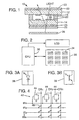
- FIG. 1 is a cross sectional view of a liquid crystal display touch screen according to the invention.
- FIG. 2 is a block diagram of one embodiment of light detecting means employed in the invention and an associated central processing unit.
- FIGS. 3A and 3B are other possible embodiments of the light detecting means.
- FIG. 4 is a diagram of a keyboard interface for signaling a detection by the light detecting means of a touch.
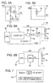
- FIGS. 5A and 5B are two embodiments of light detecting switches that may be used in the keyboard interface of FIG. 4.
- FIGS. 6A and 6B are two embodiments of means for adjusting the detection threshold of the light detecting means.
- FIG. 7 is a top view of a liquid crystal display showing locations of "keys" that must be touched for the light detecting means to detect the touch.
- FIG. 1 is a cross sectional view of an LCD touch screen 10 according to the invention.
- Parallel upper glass sheet 12 and a lower glass sheet 14 are separated by spacers 16.
- Sandwiched between the glass sheets is a thin layer of liquid crystal material 18.
- the inner surface of each piece of glass 12, 14 is coated with a transparent, conductive layer 20 of metal oxide.
- Affixed to the outer surface of upper glass sheet 12 is an upper polarizer 22 which comprises the display's viewing surface 23.
- Affixed to the outer surface of glass sheet 14 is a lower polarizer 24.
- Forming the back surface of the liquid crystal display is a transflector 26 adjacent to the lower polarizer 24.
- a transflector as defined herein, transmits some of the light striking its surface and reflects some light.
- transflector is transflective film available from Nitto Electric Industrial Co., Ltd of Osaka, Japan.
- Adjacent to transflector 26 is a light detecting means such as an array 28 of light dependent resistors (LDRs) whose resistance varies with the intensity of light detected.
- LDRs light dependent resistors
- the resistance increases as the light intensity decreases, such as occurs when a shadow is cast on the viewing surface 23.
- such means are employed for detecting a change in the light transmitted through transflector 26 caused by a touching of viewing surface 23.
- the two polarizers 22 and 24 are rotated 90 degrees from each other so normally no light would pass through both polarizers.
- the crystals of the intervening liquid crystal material when not under the influence of an electric field, rotate the polarization of light passing through them by 90 degrees.
- the polarized light that passes through upper polarizer 22 is rotated by liquid crystal material 18 so that it also passes through the lower polarizer 24.
- the passed light then strikes transflector 26, which reflects some of the light back through the display and transmits some of the light onto light detecting array 28, as indicated by the dashed lines in FIG. 1. From the viewing surface 23, the liquid crystal display in this state appears to have a silver color.
- FIG. 2 shows array 28 connected to a control means such as a central processing unit (CPU) 32, which also controls the display of the LCD via material 18 and layers 20.
- Array 28 is shown as a set of LDRs 34 for illustration, but it will be understood by those skilled in the art that the light detecting means is not so limited.
- the light detecting means may be any type of device such as a light dependent resistor, phototransistor, photodiode, solar cell or photocell which is capable of sensing such a change in ambient light filtered through a transflector on an LCD.
- FIGS. 3A and 3B illustrate two such alternative devices, a photodiode 36 and phototransistor 38.
- signaling means For communicating a detected touch to the CPU 32 or another device, signaling means may be provided.
- signaling means in the form of a keyboard interface produces a signal in response to a shadow from a touch of the viewing surface 23. This signal also indicates the location of touch on the viewing surface.
- FIG. 4 shows one example of such signaling means in the form of a conventional keyboard interface 42 into which light detecting array 28 has been integrated.
- the interface 42 comprises a matrix of cross-conductive lines coupled together at several intersections by separate light dependent switches 44 and at other intersections by mechanical switches 46.
- Lines OR1-ORn are lines from output registers of CPU 32 and line IR1-IRn are lines to input registers of the CPU.
- switches 46 and switches 44 represent keys.
- the switches 46 are conventional keys such as appear on a computer or calculator keyboard and the switches 44 underlie displayed "keys" formed by dots and segments in the liquid crystal display.
- Switch 44 may be of several designs, such as shown in FIGS. 5A and 5B.
- FIG. 4 is shown with the switch design of FIG. 5A.
- an LDR 34 forms a voltage divider with a resistor 48 from an OR line to ground.
- a transistor Q1 has its emitter connected to the OR line and its base connected to the node between the two resistors 34 and 48.
- the collector of Q1 is connected to an IR line.
- LDR 34 When not covered, LDR 34 has low resistance and transistor Q1 is off, the voltage at the base being about equal to the voltage at the emitter. With Q1 off, the collector is pulled to ground through a third resistor 50 and produces a logic low signal regardless of the voltage on the OR line.
- FIG. 5B shows an alternative design, in which the LDR 34 is connected directly between the OR line and the IR line. This design, however, produces a signal inversion on the IR line. If the OR line is high and LDR 34 is covered, the IR line is driven low because of the voltage drop across the LDR. If the LDR is not covered, indicating no touch, the IR line is pulled high. As discussed below, the signal on the IR line must thus be inverted before being read by the input registers of the CPU 32.
- each displayed key may be actuated by touching the viewing surface to cast a shadow over the underlying switch 44.
- the interface 42 is scanned by the CPU 32 by strobing output register lines OR1-ORn individually with high logic signals. If an LDR 34 within a switch 44 is covered by a touch, the output of the switch will be high. Input register lines IR1-IRn are then each examined by the CPU for a logic high signal indicating a touch opposite a switch 44 or a press of a switch 46.
- IRT line for IRTouch
- the signal inversion and pull down resistor of the line would likely be done outside the interface 42 and within an integrated circuit before being read by the CPU.
- Non-strobed OR lines should be allowed to float to prevent voltage interactions on IRT.
- the intensity of the ambient light passing through surface 23 may change for reasons other than the touching of the surface.
- ambient light indoors may vary from the light outdoors, especially on sunny days, or a non-touching portion of a finger may cast a shadow over another portion of array 28. It may be desirable, therefore, to distinguish between lighter shadows from these sources and darker shadows from an actual touch of surface 23.
- One approach for distinguishing changes in light levels is a threshold adjustment means. Such means can adjust the threshold level of transmitted light that must be detected by the LDRs 34 to indicate a touching of the viewing surface 23.
- FIGS. 6A and 6B Several techniques for adjusting the threshold are shown in FIGS. 6A and 6B.
- an LDR 34 in array 28 is shown connected to a comparator 60.
- the comparator compares a voltage Vrc measured between LDR 34 and a capacitor 64 against a reference voltage Vref.
- the output of comparator 60 is inverted and applied to an AND gate 66 whose other inputs include an OR line 68 and a clock line 70.
- an RC circuit is formed with LDR 34 and capacitor 64 to ground.
- gate 66 produces pulses that are counted by a counter 72 until Vrc exceeds Vref.
- the output of the counter is then read by CPU 32.
- the pulse count obtained during the strobe is a measure of the light intensity hitting LDR 34: the lower the intensity (caused by a darker shadow), the greater the resistance and the higher the count.
- the CPU 32 may then compare the count against other counts obtained from adjacent LDRs as well as a reference count to determine if and where the surface 23 has been touched. Any variation in sensitivity of the separate LDRs may be taken into account by the CPU 32 in reviewing the counts versus a reference count. If the LDRs 34 within the array 28 uniformly show a change in light intensity, the CPU may judge this to be a change in ambient light and adjust Vref or the reference count appropriately.
- FIG. 6B shows an alternative embodiment of a threshold adjustment means which is simpler in design.
- the voltage Vd between LDR 34 and a resistor 74 to ground is applied as the analog input to an analog-to-digital converter (ADC) 76.
- ADC analog-to-digital converter
- Vd is converted by the ADC into a digital value that may be compared against reference digital values to determine if and where the surface 23 has been touched.
- the reference values may be adjusted if the LDRs 34 across array 28 uniformly show a change in detected light intensity.
- the threshold adjustment means may be inserted between the CPU 32 and the OR and IR lines shown in FIG. 4. To reduce cost, one or more adjustment means may be switched among the different LDRs as they are strobed. Refinements are also possible. If the LCD is part of a device that is stored in a case that may be open and closed, the adjustment means may further be designed to distinguish between a change in light intensity caused by a touch or case closure. One technique could be to compare values received from the various LDRs to see if the entire array appears to be covered at one time. If so, the device may be shut off since it can no longer be viewed. This technique could also be applied to detect a total lack of ambient light, as caused by shutting off the lights in a room.
- CPU 32 is programmed to indicate where the viewing surface 23 must be touched for the underlying LDRs 34 to detect the touch.
- An example of keys displayed at the viewing surface is shown in FIG. 7. These keys may also be "soft" keys, in that their functions can be redefined by the device incorporating the touch screen 10. Labels associated with each displayed key, such as GO and STOP in FIG. 7, would change to reflect the present function.
Description
- This invention relates to optically-based touch sensitive screens, and more particularly to such screens for use with liquid crystal displays (LCDs).
- Touch sensitive screens ("touch screens") are devices that typically mount over a display such as a CRT. With a touch screen, a user can select from options displayed on the display's viewing surface by touching the surface adjacent to the desired option, or, in some designs, touching the option directly. Common techniques employed in these devices for detecting the location of a touch include mechanical buttons, crossed beams of infrared light, acoustic surface waves, capacitance sensing, and resistive membranes.
- For example, U.S. Pat. No. 4,484,179 discloses an optically-based touch screen comprising a flexible clear membrane supported above a glass screen whose edges are fitted with photodiodes. When the membrane is flexed into contact with the screen by a touch, light which previously would have passed through the membrane and glass screen is trapped between the screen surfaces by total internal reflection. This trapped light travels to the edge of the glass screen where it is detected by the photodiodes which produce a corresponding output signal. The touch position is determined by coordinating the position of the CRT raster beam with the timing of the output signals from the several photodiodes.
- U.S. Pat. No. 4,782,328, on the other hand, relies on reflection of ambient light from the actual touch source, such as a finger or pointer, into a pair of photosensors mounted at corners of the touch screen. By measuring the intensity of the reflected light received by each photosensor, a computer can calculate the location of the touch source with reference to the screen.
- Touch screens that have a transparent surface which mounts between the user and the display's viewing surface have several drawbacks. The transparent surface may cause multiple reflections on the viewing surface, produce glare and reduce the contrast ratio between displayed segments and the display background. These problems are greatest with LCDs that rely solely on absorption of ambient light to differentiate displayed dots or segments from a reflective background. Without additional lighting, the quality of an LCD image viewed through such an intervening surface is considerably reduced.
- An example of such a touch screen is found in EP-A-0 165 548, the additional transparent surface being provided by a protection glass plate. In this arrangement, the position of a user's finger is detected by the shadow cast on a photodetector array disposed beneath a liquid crystal device.
- It would therefore be desirable to provide an improved LCD touch screen, and in particular a touch screen that responds to changes in ambient light entering the LCD caused by a user touching the LCD's viewing surface.
- It would further be desirable to provide an LCD touch screen that is not positioned between the user and the display's viewing surface.
- In accordance with the present invention, there is provided a touch screen as defined by
claim 1. - The partially reflective back surface preferably constitutes a transreflective film.
- Touching casts a distinct shadow over a portion of the viewing surface and thereby limits the amount of light transmitted through a portion of the partially reflective back surface. The light detecting means may be any type of device such as a light dependent resistor (LDR) , phototransistor, photodiode, solar cell or photocell which is capable of sensing such a change in ambient light filtered through a transflector on an LCD.
- The touch screen may also include a threshold adjustment means, if desired, to distinguish between a touch shadow and other causes of a change in ambient light at the viewing surface. Such means may adjust the threshold level of transmitted light that the light detecting means must detect to indicate a touching of the viewing surface.
- For use with the touch screen, signaling means may be connected to the light detecting means. The signaling means produces a signal in response to a detection of a change in transmitted light caused by a touching of the viewing surface. The signal indicates the location of the touch. An example of such signaling means is a keyboard interface.
- The touch screen may be integrated with the LCD, such as by having the LCD display "keys" on its viewing surface on top of separate light detecting means that correspond to the displayed keys. For this integration, means are provided for controlling the LCD to indicate where the viewing surface must be touched for the light detecting means to detect the touch. An example of such means is a central processing unit that controls the LCD and responds to the light detecting means.
- The foregoing and other objects, features and advantages of the invention will become more apparent from the following detailed description which refers to the accompanying drawings.
- FIG. 1 is a cross sectional view of a liquid crystal display touch screen according to the invention.
- FIG. 2 is a block diagram of one embodiment of light detecting means employed in the invention and an associated central processing unit.
- FIGS. 3A and 3B are other possible embodiments of the light detecting means.
- FIG. 4 is a diagram of a keyboard interface for signaling a detection by the light detecting means of a touch.
- FIGS. 5A and 5B are two embodiments of light detecting switches that may be used in the keyboard interface of FIG. 4.
- FIGS. 6A and 6B are two embodiments of means for adjusting the detection threshold of the light detecting means.
- FIG. 7 is a top view of a liquid crystal display showing locations of "keys" that must be touched for the light detecting means to detect the touch.
- FIG. 1 is a cross sectional view of an
LCD touch screen 10 according to the invention. Parallelupper glass sheet 12 and alower glass sheet 14 are separated byspacers 16. Sandwiched between the glass sheets is a thin layer ofliquid crystal material 18. The inner surface of each piece ofglass conductive layer 20 of metal oxide. Affixed to the outer surface ofupper glass sheet 12 is anupper polarizer 22 which comprises the display'sviewing surface 23. Affixed to the outer surface ofglass sheet 14 is alower polarizer 24. Forming the back surface of the liquid crystal display is atransflector 26 adjacent to thelower polarizer 24. A transflector, as defined herein, transmits some of the light striking its surface and reflects some light. One example of a transflector is transflective film available from Nitto Electric Industrial Co., Ltd of Osaka, Japan. Adjacent totransflector 26 is a light detecting means such as anarray 28 of light dependent resistors (LDRs) whose resistance varies with the intensity of light detected. In the present embodiment, the resistance increases as the light intensity decreases, such as occurs when a shadow is cast on theviewing surface 23. As more fully set forth below, such means are employed for detecting a change in the light transmitted throughtransflector 26 caused by a touching ofviewing surface 23. - The two
polarizers liquid crystal material 18, when not under the influence of an electric field, rotate the polarization of light passing through them by 90 degrees. Thus, the polarized light that passes throughupper polarizer 22 is rotated byliquid crystal material 18 so that it also passes through thelower polarizer 24. The passed light then strikestransflector 26, which reflects some of the light back through the display and transmits some of the light ontolight detecting array 28, as indicated by the dashed lines in FIG. 1. From theviewing surface 23, the liquid crystal display in this state appears to have a silver color. - When an electric field is applied to
liquid crystal material 18, its crystals are aligned and the polarization of light passing through them is not affected. The light striking thelower polarizer 24 is then absorbed and, from theviewing surface 23, the display appears black instead of silver. The electric field is applied tomaterial 18 through the opposinglayers 20 of metal oxide, which are etched to form the individual dots and segments of the liquid crystal display. Etched metal oxide layers 20 are illustrated in FIG. 1. - FIG. 2 shows
array 28 connected to a control means such as a central processing unit (CPU) 32, which also controls the display of the LCD viamaterial 18 and layers 20.Array 28 is shown as a set ofLDRs 34 for illustration, but it will be understood by those skilled in the art that the light detecting means is not so limited. The light detecting means may be any type of device such as a light dependent resistor, phototransistor, photodiode, solar cell or photocell which is capable of sensing such a change in ambient light filtered through a transflector on an LCD. FIGS. 3A and 3B illustrate two such alternative devices, aphotodiode 36 andphototransistor 38. When a finger or other object touches theviewing surface 23, it casts a shadow on the surface and thereby limits the light transmitted through thetransflector 26 toarray 28. This change in transmitted light affects the resistance of one ormore LDRs 34. These LDRs communicate this change to theCPU 32 as a touching of thesurface 23. - For communicating a detected touch to the
CPU 32 or another device, signaling means may be provided. In the present embodiment signaling means in the form of a keyboard interface produces a signal in response to a shadow from a touch of theviewing surface 23. This signal also indicates the location of touch on the viewing surface. FIG. 4 shows one example of such signaling means in the form of aconventional keyboard interface 42 into which light detectingarray 28 has been integrated. Theinterface 42 comprises a matrix of cross-conductive lines coupled together at several intersections by separate lightdependent switches 44 and at other intersections bymechanical switches 46. Lines OR1-ORn are lines from output registers ofCPU 32 and line IR1-IRn are lines to input registers of the CPU. In the context of a keyboard, switches 46 and switches 44 represent keys. Theswitches 46 are conventional keys such as appear on a computer or calculator keyboard and theswitches 44 underlie displayed "keys" formed by dots and segments in the liquid crystal display. -
Switch 44 may be of several designs, such as shown in FIGS. 5A and 5B. FIG. 4 is shown with the switch design of FIG. 5A. In FIG. 5A, anLDR 34 forms a voltage divider with aresistor 48 from an OR line to ground. A transistor Q1 has its emitter connected to the OR line and its base connected to the node between the tworesistors LDR 34 has low resistance and transistor Q1 is off, the voltage at the base being about equal to the voltage at the emitter. With Q1 off, the collector is pulled to ground through athird resistor 50 and produces a logic low signal regardless of the voltage on the OR line. If theLDR 34 is covered, however, its resistance increases and the voltage at the base of Q1 rises as the relative values of resistances in the voltage divider change. If a high logic signal is applied concurrently to the OR line as during the normal strobing of the keyboard, Q1 will then conduct and the collector will produce a high logic signal. FIG. 5B shows an alternative design, in which theLDR 34 is connected directly between the OR line and the IR line. This design, however, produces a signal inversion on the IR line. If the OR line is high andLDR 34 is covered, the IR line is driven low because of the voltage drop across the LDR. If the LDR is not covered, indicating no touch, the IR line is pulled high. As discussed below, the signal on the IR line must thus be inverted before being read by the input registers of theCPU 32. - Referring again to FIG. 4, each displayed key may be actuated by touching the viewing surface to cast a shadow over the
underlying switch 44. To determine if aswitch 44 has detected a touch or if aswitch 46 has been pressed, theinterface 42 is scanned by theCPU 32 by strobing output register lines OR1-ORn individually with high logic signals. If anLDR 34 within aswitch 44 is covered by a touch, the output of the switch will be high. Input register lines IR1-IRn are then each examined by the CPU for a logic high signal indicating a touch opposite aswitch 44 or a press of aswitch 46. - If the switch embodiment of FIG. 5B is preferred, then a separate special IRT line (for IRTouch) should be used for the
switches 44. The signal inversion and pull down resistor of the line would likely be done outside theinterface 42 and within an integrated circuit before being read by the CPU. Non-strobed OR lines should be allowed to float to prevent voltage interactions on IRT. - The intensity of the ambient light passing through
surface 23 may change for reasons other than the touching of the surface. For example, ambient light indoors may vary from the light outdoors, especially on sunny days, or a non-touching portion of a finger may cast a shadow over another portion ofarray 28. It may be desirable, therefore, to distinguish between lighter shadows from these sources and darker shadows from an actual touch ofsurface 23. One approach for distinguishing changes in light levels is a threshold adjustment means. Such means can adjust the threshold level of transmitted light that must be detected by theLDRs 34 to indicate a touching of theviewing surface 23. - Several techniques for adjusting the threshold are shown in FIGS. 6A and 6B. In FIG. 6A, an
LDR 34 inarray 28 is shown connected to acomparator 60. The comparator compares a voltage Vrc measured betweenLDR 34 and a capacitor 64 against a reference voltage Vref. The output ofcomparator 60 is inverted and applied to an ANDgate 66 whose other inputs include an ORline 68 and aclock line 70. When the OR line is strobed high, an RC circuit is formed withLDR 34 and capacitor 64 to ground. As Vrc rises,gate 66 produces pulses that are counted by acounter 72 until Vrc exceeds Vref. The output of the counter is then read byCPU 32. The pulse count obtained during the strobe is a measure of the light intensity hitting LDR 34: the lower the intensity (caused by a darker shadow), the greater the resistance and the higher the count. TheCPU 32 may then compare the count against other counts obtained from adjacent LDRs as well as a reference count to determine if and where thesurface 23 has been touched. Any variation in sensitivity of the separate LDRs may be taken into account by theCPU 32 in reviewing the counts versus a reference count. If theLDRs 34 within thearray 28 uniformly show a change in light intensity, the CPU may judge this to be a change in ambient light and adjust Vref or the reference count appropriately. - FIG. 6B shows an alternative embodiment of a threshold adjustment means which is simpler in design. The voltage Vd between
LDR 34 and aresistor 74 to ground is applied as the analog input to an analog-to-digital converter (ADC) 76. When the OR line is strobed high, Vd is converted by the ADC into a digital value that may be compared against reference digital values to determine if and where thesurface 23 has been touched. As in the first embodiment, the reference values may be adjusted if the LDRs 34 acrossarray 28 uniformly show a change in detected light intensity. - The threshold adjustment means may be inserted between the
CPU 32 and the OR and IR lines shown in FIG. 4. To reduce cost, one or more adjustment means may be switched among the different LDRs as they are strobed. Refinements are also possible. If the LCD is part of a device that is stored in a case that may be open and closed, the adjustment means may further be designed to distinguish between a change in light intensity caused by a touch or case closure. One technique could be to compare values received from the various LDRs to see if the entire array appears to be covered at one time. If so, the device may be shut off since it can no longer be viewed. This technique could also be applied to detect a total lack of ambient light, as caused by shutting off the lights in a room. - To use the
touch screen 10,CPU 32 is programmed to indicate where theviewing surface 23 must be touched for theunderlying LDRs 34 to detect the touch. An example of keys displayed at the viewing surface is shown in FIG. 7. These keys may also be "soft" keys, in that their functions can be redefined by the device incorporating thetouch screen 10. Labels associated with each displayed key, such as GO and STOP in FIG. 7, would change to reflect the present function. - I have illustrated and described the principles of the invention in several embodiments. These embodiments are but examples, and it should be apparent to those skilled in the art that the invention can be modified in arrangement and detail within the scope of the claims.
Claims (14)
- A touch screen (10) comprising:a liquid crystal display having a viewing surface (23) through which light passes into and out of the display and a partially reflective back surface (26) for reflecting some of the light back through the display and for transmitting some of the light, the substance through which the light travels between the viewing surface (23) and liquid crystal material being substantially solid throughout, the arrangement being such that, in normal use, a user places a finger on the viewing surface (23);the touch screen further comprising:light detecting means (28) for detecting a change in the light transmitted through the back surface caused by a user so touching the viewing surface (23); andthreshold adjusting means (60-76) for adjusting the threshold level of transmitted light that the light detecting means (28) must detect to indicate a touching of the viewing surface.
- The touch screen of claim 1 in which the light detecting means (28) comprises a light dependent resistor (34) whose resistance varies with the intensity of the light detected.
- The touch screen of claim 1 in which the light detecting means (28) comprises a phototransistor (38).
- The touch screen of claim 1 in which the light detecting means (28) comprises a photodiode (36).
- The touch screen of any preceding claim in which the threshold adjustment means comprises a comparator (60) for comparing output of the light detecting means (28) against an adjustable reference level.
- The touch screen of any one of claims 1 to 4 in which the threshold adjustment means comprises an analog-to-digital converter (76) for comparing output of the light detecting means (28) against an adjustable reference level.
- The touch screen of any preceding claim including signalling means (42) coupled to the light detecting means (28) for producing a signal in response to a detection of a change in transmitted light caused by a touching of the viewing surface (23), the signal produced indicating the location of the touch.
- The touch screen of claim 7 in which the signalling means comprises a keyboard interface (42) having a matrix of conductive lines coupled together at intersections by separate light detecting means (34, 44), each light detecting means being a key that may be actuated by touching the viewing surface at a location that limits the light transmitted to the light detecting means.
- The touch screen of any one of claims 1 to 6 in which the light detecting means (28) comprises a plurality of separate light detecting devices.
- The touch screen of claim 9, further comprising: a keyboard interface (42) comprising a conductive line connected to each separate light detecting means, each such means being a key that may be actuated by touching the viewing surface at a location that limits the light transmitted to the light detecting means sufficiently for the means to change the logic state of a signal on the connected line.
- The touch screen of claim 10 in which the light detecting means comprises light dependent switches (44) and the keyboard interface (42) includes a matrix of conductive lines coupled together at intersections by separate light dependent switches.
- The touch screen of claim 11 in which the keyboard interface includes lines connected to switches (46) other than light detecting switches.
- The touch screen of any preceding claim including means (32) for controlling the liquid crystal display to indicate where the viewing surface must be touched for the light detecting means (28) to detect the touch.
- The touch screen of any preceding claim, wherein said light detecting means (28) are located adjacent to the partially reflective back surface of the liquid crystal display.
Applications Claiming Priority (2)
| Application Number | Priority Date | Filing Date | Title |
|---|---|---|---|
| US529099 | 1990-05-25 | ||
| US07/529,099 US5105186A (en) | 1990-05-25 | 1990-05-25 | Lcd touch screen |
Publications (2)
| Publication Number | Publication Date |
|---|---|
| EP0458513A1 EP0458513A1 (en) | 1991-11-27 |
| EP0458513B1 true EP0458513B1 (en) | 1997-11-05 |
Family
ID=24108519
Family Applications (1)
| Application Number | Title | Priority Date | Filing Date |
|---|---|---|---|
| EP91304329A Expired - Lifetime EP0458513B1 (en) | 1990-05-25 | 1991-05-14 | LCD touch screen |
Country Status (6)
| Country | Link |
|---|---|
| US (1) | US5105186A (en) |
| EP (1) | EP0458513B1 (en) |
| JP (1) | JP3385038B2 (en) |
| CA (1) | CA2038598C (en) |
| DE (1) | DE69128106T2 (en) |
| SG (1) | SG47749A1 (en) |
Families Citing this family (185)
| Publication number | Priority date | Publication date | Assignee | Title |
|---|---|---|---|---|
| US5355149A (en) * | 1992-05-27 | 1994-10-11 | Spacelabs Medical, Inc. | Scanning system for touch screen keyboards |
| US5577848A (en) * | 1992-08-24 | 1996-11-26 | Bowen; James H. | Light controlled touch pad for cursor and selection control on a computer display |
| US5605406A (en) * | 1992-08-24 | 1997-02-25 | Bowen; James H. | Computer input devices with light activated switches and light emitter protection |
| US5378069A (en) * | 1992-08-24 | 1995-01-03 | Product Engineering & Mfg., Inc. | Environmentally safe touch typing keyboard |
| JP2774424B2 (en) * | 1992-12-07 | 1998-07-09 | シャープ株式会社 | Image input integrated display device |
| US5424756A (en) * | 1993-05-14 | 1995-06-13 | Ho; Yung-Lung | Track pad cursor positioning device and method |
| US5564974A (en) * | 1994-09-06 | 1996-10-15 | Cummins-Allison Corp. | Coin sorting system with touch screen device |
| US5573457A (en) * | 1995-03-07 | 1996-11-12 | Cummins-Allison Corp. | Coin Wrapping system with touch screen device |
| US5943655A (en) * | 1995-06-06 | 1999-08-24 | Cummins-Allison Corp. | Cash settlement machine |
| DE19720925B4 (en) * | 1996-05-29 | 2004-08-26 | Nawotec Gmbh | Device for entering information by means of an object approaching the device |
| US5786801A (en) * | 1996-09-06 | 1998-07-28 | Sony Corporation | Back light control apparatus and method for a flat display system |
| US5936615A (en) * | 1996-09-12 | 1999-08-10 | Digital Equipment Corporation | Image-based touchscreen |
| US6061177A (en) * | 1996-12-19 | 2000-05-09 | Fujimoto; Kenneth Noboru | Integrated computer display and graphical input apparatus and method |
| US6039645A (en) | 1997-06-24 | 2000-03-21 | Cummins-Allison Corp. | Software loading system for a coin sorter |
| GB9722766D0 (en) | 1997-10-28 | 1997-12-24 | British Telecomm | Portable computers |
| US7663607B2 (en) | 2004-05-06 | 2010-02-16 | Apple Inc. | Multipoint touchscreen |
| US6052132A (en) * | 1998-02-06 | 2000-04-18 | Digital Equipment Corporation | Technique for providing a computer generated face having coordinated eye and head movement |
| US6400830B1 (en) | 1998-02-06 | 2002-06-04 | Compaq Computer Corporation | Technique for tracking objects through a series of images |
| US6043827A (en) * | 1998-02-06 | 2000-03-28 | Digital Equipment Corporation | Technique for acknowledging multiple objects using a computer generated face |
| US6556708B1 (en) | 1998-02-06 | 2003-04-29 | Compaq Computer Corporation | Technique for classifying objects within an image |
| US6434271B1 (en) | 1998-02-06 | 2002-08-13 | Compaq Computer Corporation | Technique for locating objects within an image |
| US6240197B1 (en) | 1998-02-06 | 2001-05-29 | Compaq Computer Corporation | Technique for disambiguating proximate objects within an image |
| US6184858B1 (en) | 1998-02-06 | 2001-02-06 | Compaq Computer Corporation | Technique for updating a background image |
| US6141434A (en) * | 1998-02-06 | 2000-10-31 | Christian; Andrew Dean | Technique for processing images |
| US6421462B1 (en) | 1998-02-06 | 2002-07-16 | Compaq Computer Corporation | Technique for differencing an image |
| US6249292B1 (en) | 1998-05-04 | 2001-06-19 | Compaq Computer Corporation | Technique for controlling a presentation of a computer generated object having a plurality of movable components |
| US6163822A (en) * | 1998-05-04 | 2000-12-19 | Compaq Computer Corporation | Technique for controlling and processing a section of an interactive presentation simultaneously with detecting stimulus event in manner that overrides process |
| DE19831978A1 (en) * | 1998-07-16 | 2000-02-03 | Micronas Intermetall Gmbh | Sensor circuit |
| DE19856007A1 (en) * | 1998-12-04 | 2000-06-21 | Bayer Ag | Display device with touch sensor |
| DE19856008C2 (en) * | 1998-12-04 | 2002-01-03 | Bayer Ag | touch sensor |
| US6864882B2 (en) | 2000-05-24 | 2005-03-08 | Next Holdings Limited | Protected touch panel display system |
| US6690363B2 (en) | 2000-06-19 | 2004-02-10 | Next Holdings Limited | Touch panel display system |
| US6803906B1 (en) | 2000-07-05 | 2004-10-12 | Smart Technologies, Inc. | Passive touch system and method of detecting user input |
| JP4485087B2 (en) * | 2001-03-01 | 2010-06-16 | 株式会社半導体エネルギー研究所 | Operation method of semiconductor device |
| DE10145248C1 (en) * | 2001-09-13 | 2003-03-20 | Krohne Messtechnik Kg | Data transmission method |
| US20030098856A1 (en) * | 2001-11-28 | 2003-05-29 | Zili Li | Selective ambient light attenuating device and associated emissive display |
| US7034799B2 (en) * | 2001-12-14 | 2006-04-25 | Samsung Electronics Co., Ltd. | Backlighting device for dual liquid crystal display and folder-type mobile phone therewith |
| AU2002336341A1 (en) * | 2002-02-20 | 2003-09-09 | Planar Systems, Inc. | Light sensitive display |
| US7053967B2 (en) | 2002-05-23 | 2006-05-30 | Planar Systems, Inc. | Light sensitive display |
| US7009663B2 (en) * | 2003-12-17 | 2006-03-07 | Planar Systems, Inc. | Integrated optical light sensitive active matrix liquid crystal display |
| US7023503B2 (en) * | 2002-02-20 | 2006-04-04 | Planar Systems, Inc. | Image sensor with photosensitive thin film transistors |
| WO2003075207A2 (en) * | 2002-03-01 | 2003-09-12 | Planar Systems, Inc. | Reflection resistant touch screens |
| US6726106B1 (en) * | 2002-04-02 | 2004-04-27 | Good Technology, Inc. | Power management and device illumination mechanisms for a personal digital assistant |
| CA2391745C (en) | 2002-06-25 | 2012-08-14 | Albert Mark David | Touch screen display using ultra-thin glass laminate |
| US7586654B2 (en) * | 2002-10-11 | 2009-09-08 | Hewlett-Packard Development Company, L.P. | System and method of adding messages to a scanned image |
| US7190416B2 (en) | 2002-10-18 | 2007-03-13 | Nitto Denko Corporation | Liquid crystal display with touch panel having internal front polarizer |
| WO2004040229A2 (en) * | 2002-10-29 | 2004-05-13 | Beamhit, Llc | Target system and method for ascertaining target impact locations of a projectile |
| US6954197B2 (en) * | 2002-11-15 | 2005-10-11 | Smart Technologies Inc. | Size/scale and orientation determination of a pointer in a camera-based touch system |
| US7219241B2 (en) * | 2002-11-30 | 2007-05-15 | Intel Corporation | Method for managing virtual and actual performance states of logical processors in a multithreaded processor using system management mode |
| US7629967B2 (en) | 2003-02-14 | 2009-12-08 | Next Holdings Limited | Touch screen signal processing |
| US8456447B2 (en) | 2003-02-14 | 2013-06-04 | Next Holdings Limited | Touch screen signal processing |
| US8508508B2 (en) * | 2003-02-14 | 2013-08-13 | Next Holdings Limited | Touch screen signal processing with single-point calibration |
| US20080084374A1 (en) * | 2003-02-20 | 2008-04-10 | Planar Systems, Inc. | Light sensitive display |
| US20080048995A1 (en) * | 2003-02-20 | 2008-02-28 | Planar Systems, Inc. | Light sensitive display |
| US7532206B2 (en) * | 2003-03-11 | 2009-05-12 | Smart Technologies Ulc | System and method for differentiating between pointers used to contact touch surface |
| US6861788B2 (en) * | 2003-06-03 | 2005-03-01 | Motorola, Inc. | Switchable display/mirror method and apparatus |
| US7432893B2 (en) * | 2003-06-14 | 2008-10-07 | Massachusetts Institute Of Technology | Input device based on frustrated total internal reflection |
| US7411575B2 (en) * | 2003-09-16 | 2008-08-12 | Smart Technologies Ulc | Gesture recognition method and touch system incorporating the same |
| WO2005029394A2 (en) * | 2003-09-22 | 2005-03-31 | Koninklijke Philips Electronics N.V. | Light guide touch screen |
| US7274356B2 (en) * | 2003-10-09 | 2007-09-25 | Smart Technologies Inc. | Apparatus for determining the location of a pointer within a region of interest |
| US20050134749A1 (en) * | 2003-12-19 | 2005-06-23 | Adiel Abileah | Reflection resistant display |
| US7355593B2 (en) | 2004-01-02 | 2008-04-08 | Smart Technologies, Inc. | Pointer tracking across multiple overlapping coordinate input sub-regions defining a generally contiguous input region |
| US20050219200A1 (en) * | 2004-03-31 | 2005-10-06 | Weng Chien-Sen | Fingerprint sensing pixel with a larger aperture |
| US7773139B2 (en) * | 2004-04-16 | 2010-08-10 | Apple Inc. | Image sensor with photosensitive thin film transistors |
| US7460110B2 (en) | 2004-04-29 | 2008-12-02 | Smart Technologies Ulc | Dual mode touch system |
| US7538759B2 (en) | 2004-05-07 | 2009-05-26 | Next Holdings Limited | Touch panel display system with illumination and detection provided from a single edge |
| US8120596B2 (en) * | 2004-05-21 | 2012-02-21 | Smart Technologies Ulc | Tiled touch system |
| US7719523B2 (en) | 2004-08-06 | 2010-05-18 | Touchtable, Inc. | Bounding box gesture recognition on a touch detecting interactive display |
| US7728821B2 (en) * | 2004-08-06 | 2010-06-01 | Touchtable, Inc. | Touch detecting interactive display |
| US7724242B2 (en) | 2004-08-06 | 2010-05-25 | Touchtable, Inc. | Touch driven method and apparatus to integrate and display multiple image layers forming alternate depictions of same subject matter |
| KR101018751B1 (en) * | 2004-09-24 | 2011-03-04 | 삼성전자주식회사 | Display device and driving method thereof |
| KR100566569B1 (en) * | 2004-10-22 | 2006-03-31 | 엠텍비젼 주식회사 | Portable terminal having inputting means using image sensor and inputting method thereof |
| US7213745B2 (en) * | 2005-06-22 | 2007-05-08 | De La Rue International Limited | Financial transactions processing system including customer display screen |
| EP1758062A3 (en) | 2005-08-23 | 2007-10-03 | De La Rue International Limited | Flexible, multi-mode financial transactions processing systems and methods |
| JP2007094158A (en) * | 2005-09-29 | 2007-04-12 | Toshiba Matsushita Display Technology Co Ltd | Liquid crystal display device |
| US20070109239A1 (en) | 2005-11-14 | 2007-05-17 | Den Boer Willem | Integrated light sensitive liquid crystal display |
| US8725845B2 (en) * | 2006-03-16 | 2014-05-13 | Exceptional Innovation Llc | Automation control system having a configuration tool |
| US7587464B2 (en) * | 2006-03-16 | 2009-09-08 | Exceptional Innovation, Llc | Device automation using networked device control having a web services for devices stack |
| US7496627B2 (en) * | 2006-03-16 | 2009-02-24 | Exceptional Innovation, Llc | Automation control system having digital logging |
| US8209398B2 (en) * | 2006-03-16 | 2012-06-26 | Exceptional Innovation Llc | Internet protocol based media streaming solution |
| US7966083B2 (en) * | 2006-03-16 | 2011-06-21 | Exceptional Innovation Llc | Automation control system having device scripting |
| US8001219B2 (en) * | 2006-03-16 | 2011-08-16 | Exceptional Innovation, Llc | User control interface for convergence and automation system |
| US8155142B2 (en) * | 2006-03-16 | 2012-04-10 | Exceptional Innovation Llc | Network based digital access point device |
| US7509402B2 (en) * | 2006-03-16 | 2009-03-24 | Exceptional Innovation, Llc | Automation control system having a configuration tool and two-way ethernet communication for web service messaging, discovery, description, and eventing that is controllable with a touch-screen display |
| WO2007126781A2 (en) * | 2006-03-27 | 2007-11-08 | Exceptional Innovation Llc | Set top box for convergence and automation system |
| WO2007124453A2 (en) * | 2006-04-20 | 2007-11-01 | Exceptional Innovation Llc | Touch screen for convergence and automation system |
| US7667968B2 (en) * | 2006-05-19 | 2010-02-23 | Exceptional Innovation, Llc | Air-cooling system configuration for touch screen |
| KR101529840B1 (en) | 2006-06-09 | 2015-06-17 | 애플 인크. | Touch screen liquid crystal display |
| US8552989B2 (en) | 2006-06-09 | 2013-10-08 | Apple Inc. | Integrated display and touch screen |
| CN104965621B (en) | 2006-06-09 | 2018-06-12 | 苹果公司 | Touch screen LCD and its operating method |
| US20070283832A1 (en) * | 2006-06-09 | 2007-12-13 | Apple Computer, Inc. | Imprint circuit patterning |
| US8203540B2 (en) * | 2006-09-05 | 2012-06-19 | Honeywell International Inc. | LCD panel with integral touchscreen |
| US7843516B2 (en) * | 2006-09-05 | 2010-11-30 | Honeywell International Inc. | LCD touchscreen panel with scanning backlight |
| US20080055495A1 (en) * | 2006-09-05 | 2008-03-06 | Honeywell International Inc. | LCD panel with synchronized integral touchscreen |
| CN100410749C (en) * | 2006-09-14 | 2008-08-13 | 友达光电股份有限公司 | Light sensed touch controlled type liquid crystal display |
| JP4567028B2 (en) * | 2006-09-26 | 2010-10-20 | エルジー ディスプレイ カンパニー リミテッド | Liquid crystal display device having multi-touch sensing function and driving method thereof |
| US7679610B2 (en) * | 2006-09-28 | 2010-03-16 | Honeywell International Inc. | LCD touchscreen panel with external optical path |
| US8022941B2 (en) * | 2006-10-12 | 2011-09-20 | Disney Enterprises, Inc. | Multi-user touch screen |
| US7969426B2 (en) * | 2006-10-31 | 2011-06-28 | Hewlett-Packard Development Company, L.P. | Light sensitive display interface for computing devices |
| WO2008073658A2 (en) * | 2006-11-09 | 2008-06-19 | Exceptional Innovation, Llc. | Portable device for convergence and automation solution |
| EP2088499A4 (en) * | 2006-11-30 | 2011-11-30 | Sega Corp | Position inputting apparatus |
| US9442607B2 (en) * | 2006-12-04 | 2016-09-13 | Smart Technologies Inc. | Interactive input system and method |
| US8493330B2 (en) | 2007-01-03 | 2013-07-23 | Apple Inc. | Individual channel phase delay scheme |
| US7812827B2 (en) * | 2007-01-03 | 2010-10-12 | Apple Inc. | Simultaneous sensing arrangement |
| US9710095B2 (en) | 2007-01-05 | 2017-07-18 | Apple Inc. | Touch screen stack-ups |
| US7844915B2 (en) | 2007-01-07 | 2010-11-30 | Apple Inc. | Application programming interfaces for scrolling operations |
| US8115753B2 (en) | 2007-04-11 | 2012-02-14 | Next Holdings Limited | Touch screen system with hover and click input methods |
| US20080303783A1 (en) * | 2007-06-07 | 2008-12-11 | Weibezahn Karl S | Touchless detection display |
| US8493331B2 (en) | 2007-06-13 | 2013-07-23 | Apple Inc. | Touch detection using multiple simultaneous frequencies |
| US8094137B2 (en) * | 2007-07-23 | 2012-01-10 | Smart Technologies Ulc | System and method of detecting contact on a display |
| AU2008280952A1 (en) * | 2007-08-30 | 2009-03-19 | Next Holdings Ltd | Low profile touch panel systems |
| CN101802760B (en) | 2007-08-30 | 2013-03-20 | 奈克斯特控股有限公司 | Optical touch screen with improved illumination |
| CN101465958A (en) * | 2007-12-17 | 2009-06-24 | 鸿富锦精密工业(深圳)有限公司 | Menu management system and method |
| US8405636B2 (en) | 2008-01-07 | 2013-03-26 | Next Holdings Limited | Optical position sensing system and optical position sensor assembly |
| TWI405167B (en) * | 2008-03-07 | 2013-08-11 | Dynascan Technology Corp | A method for attenuating compensation of liquid crystal display with LED backlight and the display |
| CN101539806B (en) * | 2008-03-21 | 2012-10-17 | 鸿富锦精密工业(深圳)有限公司 | Electronic equipment and keyboard thereof |
| US20090278816A1 (en) * | 2008-05-06 | 2009-11-12 | Next Holdings Limited | Systems and Methods For Resolving Multitouch Scenarios Using Software Filters |
| US20090278795A1 (en) * | 2008-05-09 | 2009-11-12 | Smart Technologies Ulc | Interactive Input System And Illumination Assembly Therefor |
| US8902193B2 (en) | 2008-05-09 | 2014-12-02 | Smart Technologies Ulc | Interactive input system and bezel therefor |
| CN101593067B (en) * | 2008-05-30 | 2012-06-20 | 鸿富锦精密工业(深圳)有限公司 | Screen controlled by adopting optical signals |
| US8508495B2 (en) | 2008-07-03 | 2013-08-13 | Apple Inc. | Display with dual-function capacitive elements |
| US9606663B2 (en) | 2008-09-10 | 2017-03-28 | Apple Inc. | Multiple stimulation phase determination |
| US8592697B2 (en) | 2008-09-10 | 2013-11-26 | Apple Inc. | Single-chip multi-stimulus sensor controller |
| US9348451B2 (en) | 2008-09-10 | 2016-05-24 | Apple Inc. | Channel scan architecture for multiple stimulus multi-touch sensor panels |
| US8368654B2 (en) * | 2008-09-30 | 2013-02-05 | Apple Inc. | Integrated touch sensor and solar assembly |
| US9323410B2 (en) * | 2008-10-13 | 2016-04-26 | Sony Ericsson Mobile Communications Ab | User input displays for mobile devices |
| US8339378B2 (en) * | 2008-11-05 | 2012-12-25 | Smart Technologies Ulc | Interactive input system with multi-angle reflector |
| US20100123665A1 (en) * | 2008-11-14 | 2010-05-20 | Jorgen Birkler | Displays for Mobile Devices that Detect User Inputs Using Touch and Tracking of User Input Objects |
| US8144295B2 (en) * | 2008-11-18 | 2012-03-27 | Apple Inc. | Common bus design for a TFT-LCD display |
| US8749496B2 (en) * | 2008-12-05 | 2014-06-10 | Apple Inc. | Integrated touch panel for a TFT display |
| SE533704C2 (en) | 2008-12-05 | 2010-12-07 | Flatfrog Lab Ab | Touch sensitive apparatus and method for operating the same |
| US20100155575A1 (en) * | 2008-12-19 | 2010-06-24 | Sony Ericsson Mobile Communications Ab | Arrangement and method in an electronic device for detecting a user input to a key |
| US20100225588A1 (en) * | 2009-01-21 | 2010-09-09 | Next Holdings Limited | Methods And Systems For Optical Detection Of Gestures |
| US8217913B2 (en) | 2009-02-02 | 2012-07-10 | Apple Inc. | Integrated touch screen |
| US7995041B2 (en) * | 2009-02-02 | 2011-08-09 | Apple Inc. | Integrated touch screen |
| US20100229090A1 (en) * | 2009-03-05 | 2010-09-09 | Next Holdings Limited | Systems and Methods for Interacting With Touch Displays Using Single-Touch and Multi-Touch Gestures |
| SE534244C2 (en) * | 2009-09-02 | 2011-06-14 | Flatfrog Lab Ab | Touch sensitive system and method for functional control thereof |
| CA2778154A1 (en) * | 2009-10-19 | 2011-04-28 | Flatfrog Laboratories Ab | Determining touch data for one or more objects on a touch surface |
| TWI395008B (en) * | 2009-10-22 | 2013-05-01 | Au Optronics Corp | Touch panel and touch display device |
| US20110095989A1 (en) * | 2009-10-23 | 2011-04-28 | Smart Technologies Ulc | Interactive input system and bezel therefor |
| TWI409534B (en) * | 2009-10-28 | 2013-09-21 | Shenzhen Laibao Hi Tech Co Ltd | A touch screen having a reflection and a passing effect, and a method of manufacturing the same |
| JP5525798B2 (en) * | 2009-11-20 | 2014-06-18 | 株式会社ニューフレアテクノロジー | Charged particle beam drawing apparatus and method for correcting charging effect thereof |
| US8436837B2 (en) * | 2010-02-25 | 2013-05-07 | Hewlett-Packard Development Company, L.P. | Stylus input system |
| US8514190B2 (en) | 2010-10-06 | 2013-08-20 | Sony Corporation | Displays for electronic devices that detect and respond to the contour and/or height profile of user input objects |
| EP2458466B1 (en) * | 2010-11-30 | 2020-02-26 | Industrial Development of Automotivo Components, IDACO corp | Automatic supervision and control system |
| US9310923B2 (en) | 2010-12-03 | 2016-04-12 | Apple Inc. | Input device for touch sensitive devices |
| US8804056B2 (en) * | 2010-12-22 | 2014-08-12 | Apple Inc. | Integrated touch screens |
| US8928635B2 (en) | 2011-06-22 | 2015-01-06 | Apple Inc. | Active stylus |
| US9329703B2 (en) | 2011-06-22 | 2016-05-03 | Apple Inc. | Intelligent stylus |
| US8638320B2 (en) | 2011-06-22 | 2014-01-28 | Apple Inc. | Stylus orientation detection |
| US10168835B2 (en) | 2012-05-23 | 2019-01-01 | Flatfrog Laboratories Ab | Spatial resolution in touch displays |
| US9395583B2 (en) | 2012-06-06 | 2016-07-19 | Apple Inc. | Column spacer design for a display incorporating a third metal layer |
| US9176604B2 (en) | 2012-07-27 | 2015-11-03 | Apple Inc. | Stylus device |
| US9557845B2 (en) | 2012-07-27 | 2017-01-31 | Apple Inc. | Input device for and method of communication with capacitive devices through frequency variation |
| US9652090B2 (en) | 2012-07-27 | 2017-05-16 | Apple Inc. | Device for digital communication through capacitive coupling |
| CN103902194A (en) * | 2012-12-28 | 2014-07-02 | 鸿富锦精密工业(武汉)有限公司 | Electronic device and control method for allowing screen image of electronic device to rotate |
| US9336723B2 (en) | 2013-02-13 | 2016-05-10 | Apple Inc. | In-cell touch for LED |
| US10048775B2 (en) | 2013-03-14 | 2018-08-14 | Apple Inc. | Stylus detection and demodulation |
| WO2014168567A1 (en) | 2013-04-11 | 2014-10-16 | Flatfrog Laboratories Ab | Tomographic processing for touch detection |
| US9874978B2 (en) | 2013-07-12 | 2018-01-23 | Flatfrog Laboratories Ab | Partial detect mode |
| US9939935B2 (en) | 2013-07-31 | 2018-04-10 | Apple Inc. | Scan engine for touch controller architecture |
| KR101984443B1 (en) | 2013-12-13 | 2019-05-30 | 애플 인크. | Integrated touch and display architectures for self-capacitive touch sensors |
| WO2015108479A1 (en) | 2014-01-16 | 2015-07-23 | Flatfrog Laboratories Ab | Light coupling in tir-based optical touch systems |
| US10126882B2 (en) | 2014-01-16 | 2018-11-13 | Flatfrog Laboratories Ab | TIR-based optical touch systems of projection-type |
| WO2015160377A1 (en) | 2014-04-16 | 2015-10-22 | Wrostix Technologies Llc | Structure for pixelated self-capacitance |
| WO2015175013A1 (en) | 2014-05-16 | 2015-11-19 | Wrostix Technologies Llc | Structure for integrated touch screen |
| US9367188B2 (en) | 2014-05-23 | 2016-06-14 | Apple Inc. | RC matching in a touch screen |
| WO2015183334A1 (en) | 2014-05-28 | 2015-12-03 | Pylemta Management Llc | Narrow border touch screen |
| EP3161594A4 (en) | 2014-06-27 | 2018-01-17 | FlatFrog Laboratories AB | Detection of surface contamination |
| US10061450B2 (en) | 2014-12-04 | 2018-08-28 | Apple Inc. | Coarse scan and targeted active mode scan for touch |
| WO2016122385A1 (en) | 2015-01-28 | 2016-08-04 | Flatfrog Laboratories Ab | Dynamic touch quarantine frames |
| US10318074B2 (en) | 2015-01-30 | 2019-06-11 | Flatfrog Laboratories Ab | Touch-sensing OLED display with tilted emitters |
| US10496227B2 (en) | 2015-02-09 | 2019-12-03 | Flatfrog Laboratories Ab | Optical touch system comprising means for projecting and detecting light beams above and inside a transmissive panel |
| EP3265855A4 (en) | 2015-03-02 | 2018-10-31 | FlatFrog Laboratories AB | Optical component for light coupling |
| WO2017099657A1 (en) | 2015-12-09 | 2017-06-15 | Flatfrog Laboratories Ab | Improved stylus identification |
| US10474277B2 (en) | 2016-05-31 | 2019-11-12 | Apple Inc. | Position-based stylus communication |
| WO2018096430A1 (en) | 2016-11-24 | 2018-05-31 | Flatfrog Laboratories Ab | Automatic optimisation of touch signal |
| EP4152132A1 (en) | 2016-12-07 | 2023-03-22 | FlatFrog Laboratories AB | An improved touch device |
| US10963104B2 (en) | 2017-02-06 | 2021-03-30 | Flatfrog Laboratories Ab | Optical coupling in touch-sensing systems |
| US10606414B2 (en) | 2017-03-22 | 2020-03-31 | Flatfrog Laboratories Ab | Eraser for touch displays |
| CN110663015A (en) | 2017-03-28 | 2020-01-07 | 平蛙实验室股份公司 | Touch sensitive device and method for assembly |
| CN111052058B (en) | 2017-09-01 | 2023-10-20 | 平蛙实验室股份公司 | Improved optical component |
| US11567610B2 (en) | 2018-03-05 | 2023-01-31 | Flatfrog Laboratories Ab | Detection line broadening |
| WO2020153890A1 (en) | 2019-01-25 | 2020-07-30 | Flatfrog Laboratories Ab | A videoconferencing terminal and method of operating the same |
| WO2021162602A1 (en) | 2020-02-10 | 2021-08-19 | Flatfrog Laboratories Ab | Improved touch-sensing apparatus |
Family Cites Families (8)
| Publication number | Priority date | Publication date | Assignee | Title |
|---|---|---|---|---|
| GB1435265A (en) * | 1974-10-01 | 1976-05-12 | Ibm | Touch keyboard |
| US4484179A (en) * | 1980-04-16 | 1984-11-20 | At&T Bell Laboratories | Touch position sensitive surface |
| US4723836A (en) * | 1983-10-26 | 1988-02-09 | Sharp Kabushiki Kaisha | Handwritten character input device |
| US4671671A (en) * | 1984-06-18 | 1987-06-09 | Casio Computer Co., Ltd. | Small electronic apparatus with optical input device |
| US4707689A (en) * | 1985-03-25 | 1987-11-17 | AT&T Information Systems Inc. American Telephone & Telegraph Company | Adaptive thresholding scheme for optically-based touch screens |
| US4782328A (en) * | 1986-10-02 | 1988-11-01 | Product Development Services, Incorporated | Ambient-light-responsive touch screen data input method and system |
| US4916308A (en) * | 1988-10-17 | 1990-04-10 | Tektronix, Inc. | Integrated liquid crystal display and optical touch panel |
| US4977315A (en) * | 1989-10-06 | 1990-12-11 | Summagraphics Corporation | Liquid crystal position determining system and wand device |
-
1990
- 1990-05-25 US US07/529,099 patent/US5105186A/en not_active Expired - Lifetime
-
1991
- 1991-03-19 CA CA002038598A patent/CA2038598C/en not_active Expired - Fee Related
- 1991-05-14 SG SG1996004195A patent/SG47749A1/en unknown
- 1991-05-14 DE DE69128106T patent/DE69128106T2/en not_active Expired - Lifetime
- 1991-05-14 EP EP91304329A patent/EP0458513B1/en not_active Expired - Lifetime
- 1991-05-24 JP JP14992691A patent/JP3385038B2/en not_active Expired - Lifetime
Also Published As
| Publication number | Publication date |
|---|---|
| CA2038598C (en) | 2002-01-08 |
| DE69128106D1 (en) | 1997-12-11 |
| JPH04232524A (en) | 1992-08-20 |
| SG47749A1 (en) | 1998-04-17 |
| US5105186A (en) | 1992-04-14 |
| DE69128106T2 (en) | 1998-02-26 |
| EP0458513A1 (en) | 1991-11-27 |
| CA2038598A1 (en) | 1991-11-26 |
| JP3385038B2 (en) | 2003-03-10 |
Similar Documents
| Publication | Publication Date | Title |
|---|---|---|
| EP0458513B1 (en) | LCD touch screen | |
| US11073926B2 (en) | Light sensitive display | |
| US9971456B2 (en) | Light sensitive display with switchable detection modes for detecting a fingerprint | |
| US8570449B2 (en) | Light sensitive display with pressure sensor | |
| US7852417B2 (en) | Light sensitive display | |
| EP3200183A1 (en) | Integrated light sensitive liquid-crystal display | |
| US20080048995A1 (en) | Light sensitive display | |
| US20170205937A1 (en) | Force Touch Display Device and Force Touch Control Method | |
| WO2003071345A1 (en) | Light sensitive display |
Legal Events
| Date | Code | Title | Description |
|---|---|---|---|
| PUAI | Public reference made under article 153(3) epc to a published international application that has entered the european phase |
Free format text: ORIGINAL CODE: 0009012 |
|
| AK | Designated contracting states |
Kind code of ref document: A1 Designated state(s): DE FR GB IT |
|
| 17P | Request for examination filed |
Effective date: 19920318 |
|
| 17Q | First examination report despatched |
Effective date: 19950216 |
|
| GRAG | Despatch of communication of intention to grant |
Free format text: ORIGINAL CODE: EPIDOS AGRA |
|
| GRAH | Despatch of communication of intention to grant a patent |
Free format text: ORIGINAL CODE: EPIDOS IGRA |
|
| GRAH | Despatch of communication of intention to grant a patent |
Free format text: ORIGINAL CODE: EPIDOS IGRA |
|
| GRAA | (expected) grant |
Free format text: ORIGINAL CODE: 0009210 |
|
| AK | Designated contracting states |
Kind code of ref document: B1 Designated state(s): DE FR GB IT |
|
| REF | Corresponds to: |
Ref document number: 69128106 Country of ref document: DE Date of ref document: 19971211 |
|
| ITF | It: translation for a ep patent filed |
Owner name: SOCIETA' ITALIANA BREVETTI S.P.A. |
|
| ET | Fr: translation filed | ||
| PLBE | No opposition filed within time limit |
Free format text: ORIGINAL CODE: 0009261 |
|
| STAA | Information on the status of an ep patent application or granted ep patent |
Free format text: STATUS: NO OPPOSITION FILED WITHIN TIME LIMIT |
|
| 26N | No opposition filed | ||
| REG | Reference to a national code |
Ref country code: GB Ref legal event code: 732E |
|
| REG | Reference to a national code |
Ref country code: FR Ref legal event code: TP |
|
| REG | Reference to a national code |
Ref country code: GB Ref legal event code: IF02 |
|
| PGFP | Annual fee paid to national office [announced via postgrant information from national office to epo] |
Ref country code: IT Payment date: 20060531 Year of fee payment: 16 |
|
| PG25 | Lapsed in a contracting state [announced via postgrant information from national office to epo] |
Ref country code: IT Free format text: LAPSE BECAUSE OF NON-PAYMENT OF DUE FEES Effective date: 20070514 |
|
| PGFP | Annual fee paid to national office [announced via postgrant information from national office to epo] |
Ref country code: FR Payment date: 20100601 Year of fee payment: 20 |
|
| PGFP | Annual fee paid to national office [announced via postgrant information from national office to epo] |
Ref country code: DE Payment date: 20100527 Year of fee payment: 20 |
|
| PGFP | Annual fee paid to national office [announced via postgrant information from national office to epo] |
Ref country code: GB Payment date: 20100401 Year of fee payment: 20 |
|
| REG | Reference to a national code |
Ref country code: DE Ref legal event code: R071 Ref document number: 69128106 Country of ref document: DE |
|
| REG | Reference to a national code |
Ref country code: GB Ref legal event code: PE20 Expiry date: 20110513 |
|
| PG25 | Lapsed in a contracting state [announced via postgrant information from national office to epo] |
Ref country code: GB Free format text: LAPSE BECAUSE OF EXPIRATION OF PROTECTION Effective date: 20110513 |
|
| PG25 | Lapsed in a contracting state [announced via postgrant information from national office to epo] |
Ref country code: DE Free format text: LAPSE BECAUSE OF EXPIRATION OF PROTECTION Effective date: 20110514 |