EP0459093A2 - Capillary inoculator and assembly for inoculating multiple test sites and method of inoculating test sites therewith. - Google Patents
Capillary inoculator and assembly for inoculating multiple test sites and method of inoculating test sites therewith. Download PDFInfo
- Publication number
- EP0459093A2 EP0459093A2 EP91103353A EP91103353A EP0459093A2 EP 0459093 A2 EP0459093 A2 EP 0459093A2 EP 91103353 A EP91103353 A EP 91103353A EP 91103353 A EP91103353 A EP 91103353A EP 0459093 A2 EP0459093 A2 EP 0459093A2
- Authority
- EP
- European Patent Office
- Prior art keywords
- capillaries
- inoculator
- liquid
- test sites
- test
- Prior art date
- Legal status (The legal status is an assumption and is not a legal conclusion. Google has not performed a legal analysis and makes no representation as to the accuracy of the status listed.)
- Granted
Links
Images


Classifications
-
- B—PERFORMING OPERATIONS; TRANSPORTING
- B01—PHYSICAL OR CHEMICAL PROCESSES OR APPARATUS IN GENERAL
- B01L—CHEMICAL OR PHYSICAL LABORATORY APPARATUS FOR GENERAL USE
- B01L3/00—Containers or dishes for laboratory use, e.g. laboratory glassware; Droppers
- B01L3/50—Containers for the purpose of retaining a material to be analysed, e.g. test tubes
- B01L3/502—Containers for the purpose of retaining a material to be analysed, e.g. test tubes with fluid transport, e.g. in multi-compartment structures
- B01L3/5027—Containers for the purpose of retaining a material to be analysed, e.g. test tubes with fluid transport, e.g. in multi-compartment structures by integrated microfluidic structures, i.e. dimensions of channels and chambers are such that surface tension forces are important, e.g. lab-on-a-chip
-
- B—PERFORMING OPERATIONS; TRANSPORTING
- B01—PHYSICAL OR CHEMICAL PROCESSES OR APPARATUS IN GENERAL
- B01L—CHEMICAL OR PHYSICAL LABORATORY APPARATUS FOR GENERAL USE
- B01L2200/00—Solutions for specific problems relating to chemical or physical laboratory apparatus
- B01L2200/06—Fluid handling related problems
- B01L2200/0689—Sealing
-
- B—PERFORMING OPERATIONS; TRANSPORTING
- B01—PHYSICAL OR CHEMICAL PROCESSES OR APPARATUS IN GENERAL
- B01L—CHEMICAL OR PHYSICAL LABORATORY APPARATUS FOR GENERAL USE
- B01L2300/00—Additional constructional details
- B01L2300/06—Auxiliary integrated devices, integrated components
- B01L2300/069—Absorbents; Gels to retain a fluid
-
- B—PERFORMING OPERATIONS; TRANSPORTING
- B01—PHYSICAL OR CHEMICAL PROCESSES OR APPARATUS IN GENERAL
- B01L—CHEMICAL OR PHYSICAL LABORATORY APPARATUS FOR GENERAL USE
- B01L2300/00—Additional constructional details
- B01L2300/08—Geometry, shape and general structure
- B01L2300/0809—Geometry, shape and general structure rectangular shaped
- B01L2300/0816—Cards, e.g. flat sample carriers usually with flow in two horizontal directions
-
- B—PERFORMING OPERATIONS; TRANSPORTING
- B01—PHYSICAL OR CHEMICAL PROCESSES OR APPARATUS IN GENERAL
- B01L—CHEMICAL OR PHYSICAL LABORATORY APPARATUS FOR GENERAL USE
- B01L2300/00—Additional constructional details
- B01L2300/08—Geometry, shape and general structure
- B01L2300/0861—Configuration of multiple channels and/or chambers in a single devices
- B01L2300/0864—Configuration of multiple channels and/or chambers in a single devices comprising only one inlet and multiple receiving wells, e.g. for separation, splitting
-
- B—PERFORMING OPERATIONS; TRANSPORTING
- B01—PHYSICAL OR CHEMICAL PROCESSES OR APPARATUS IN GENERAL
- B01L—CHEMICAL OR PHYSICAL LABORATORY APPARATUS FOR GENERAL USE
- B01L2300/00—Additional constructional details
- B01L2300/08—Geometry, shape and general structure
- B01L2300/0887—Laminated structure
-
- B—PERFORMING OPERATIONS; TRANSPORTING
- B01—PHYSICAL OR CHEMICAL PROCESSES OR APPARATUS IN GENERAL
- B01L—CHEMICAL OR PHYSICAL LABORATORY APPARATUS FOR GENERAL USE
- B01L2400/00—Moving or stopping fluids
- B01L2400/04—Moving fluids with specific forces or mechanical means
- B01L2400/0403—Moving fluids with specific forces or mechanical means specific forces
- B01L2400/0406—Moving fluids with specific forces or mechanical means specific forces capillary forces
Definitions
- the present invention relates generally to an inoculator for inoculating test sites with small volumes of a liquid or suspension.
- the inoculator may be used to divide a liquid sample into small, discrete volumes and dispense these volumes.
- a multiple-channel pipette assembly including multiple tips can be employed to reduce the number of procedures necessary to inoculate all of the sites, but tip contamination would still be a concern and the positioning of the tips is more difficult.
- Single and multiple-channel pipettes are generally not used for depositing very small liquid samples in the 3-5 microliter range due to poor repeatability.
- a second group of devices used to deposit small and usually equal volumes of a liquid sample are devices generally known as Steers Replicators.
- Such replicators include a hand-held body including an array of pins protruding downwardly from the body and arrayed as required for the intended inoculation procedure.
- Each pin has a blunt, concave or slotted tip.
- the tips of the pins contact the liquid sample, the bottom surfaces thereof each retain a specific volume of liquid due to surface tension. These tips are then moved into contact with the test sites which are inoculated as the liquid is transferred thereto.
- the actual amounts of liquid transferred to the test sites are dependent upon the materials from which the pins are made, the liquid surface tension, the materials present at the test sites, and evaporation to room air.
- Replicators of this type may also tend to entrap air as the geometries of the tips often do not allow the air to escape as the liquid adheres thereto.
- the liquid sample to be transferred by the replicator must first be poured into a flat tray so that the pins can be dipped therein. The tray must then be carefully disposed of without spilling.
- the replicators are most commonly made from stainless steel and are therefore not disposable. They accordingly must be sterilized once the test sites have been inoculated.
- U.S. Patent No. 4,808,316 This device includes a substantially rigid, planar frame, a plurality of test wells, a filling manifold in fluid communication with the test wells, and a venting manifold in fluid communication with the test wells.
- the test wells each contain an appropriate reagent which is reactive with a fluid sample deposited therein. The fluid sample is supplied to the test wells by a gravity feed through the filling manifold.
- test wells Vacuum filling techniques for filling test wells within cards are disclosed in U.S. Patent Nos. 3,957,583, 4,018,652, 4,116,775, 4,207,394, and 4,318,994.
- Each of the test wells contains some combination of culture medium, antibiotic, and indicator reagents.
- Microorganism suspensions are drawn into the test wells by evacuating most of the air from the cavities. Then the liquid is drawn in when ambient pressure is restored. Light transmission readings of the test wells are made through the thickness of the panel.
- the supports may be made from alpha cellulose, pH neutralized glass fiber, or other such absorbent materials.
- the supports may be secured to a carrier such as a card or other surface support, or positioned within test wells formed within a tray. In either instance, it is important to inoculate each support site with a precise volume of analyte so that the test is accurate and repeatable site-to-site and test-to-test.
- An inoculator in accordance with the present invention comprises a carrier including a base and side walls which define a reservoir, and a plurality of capillaries extending through the base of said carrier and in fluid communication with the reservoir.
- Each of the capillaries is preferably formed as a bore within and extending through the base.
- the base of the carrier preferably includes a plurality of projections through which the capillaries respectively extend.
- the projections are preferably formed with tapered ends such as the conical ends normally used for the delivery end of a pipette to provide superior liquid retention within the capillaries while facilitating liquid transfer to the test sites.
- the use of projections allows the capillaries to be filled by immersing them in a reservoir. If filling is to be accomplished in such a manner, the carrier need not include a reservoir formed as an integral part thereof.
- An absorbent trap is preferably provided adjacent to the reservoir, if incorporated with the carrier, for absorbing excess liquid.
- an inoculating assembly which comprises a carrier including a plurality of capillaries extending therethrough and a test device positioned adjacent to the carrier, the device including test sites in registry with the respective capillaries.
- Each of the test sites preferably includes an absorbent support which is capable of drawing liquid from the respective capillaries by wicking action.
- a compressible member is preferably mounted between the carrier and device for separating the ends of the capillaries from the test sites prior to initiating the inoculation procedure. Pressure exerted upon the carrier urges the ends of the capillaries into contact with the test sites, thereby causing the transfer of liquid thereto.
- the carrier preferably includes a plurality of projections through which each capillary extends. Each projection is preferably formed with a tapered end which is positioned in opposing relation to one of the test sites.
- a method in accordance with the present invention includes the steps of providing a carrier including a plurality of capillaries extending therethrough, providing a liquid within each of the capillaries, aligning the capillaries with a plurality of test sites, and causing the liquid within each of the capillaries to be transferred to the respective test sites.
- Such liquid transferral is preferably accomplished by moving the carrier towards the test device until the capillaries contact the respective test sites.
- Each test site is preferably provided with an absorbent substrate which draws the liquid from each capillary via wicking action.
- the method includes the steps of contacting the capillaries with a liquid and substantially completely filling each of the capillaries.
- the capillaires are partially or entirely filled via capillary action.
- the assembly includes an inoculator 12 and a test device which may be in the form of a panel 14 which is matched to the inoculator.
- a compressible member such as a foam gasket 16 is positioned between the inoculator 12 and test panel 14, and separates them by an appropriate distance when the gasket is in the "relaxed" position.
- the inoculator includes a generally trough-shaped carrier 18 which is preferably of integral construction and molded from a polymeric material such as transparent polystyrene resin. It is important that the resin be of high purity and that no silicone release agents are used in the molding process. This is necessary to provide an inoculator having clean surfaces of controlled hydrophobicity, the importance of which shall be explained below.
- the carrier 18 has a base 20 including a substantially flat upper surface 22, peripheral side walls 24 projecting from the upper surface 22, and two rows of capillaries 26.
- the base and side walls define a reservoir or trough.
- Each of the capillaries extends through the base and includes an upper opening adjoining the upper surface 22 of the carrier base and in fluid communication with the reservoir. Filling of the capillaries is facilitated if they are substantially tangent to the side walls 24.
- Two rows of projections 28 extend from the lower surface of the carrier base 20.
- Each projection includes a tapered end 30 adjoining the bottom opening of each capillary.
- These tapered ends of the projections which with the carrier base 20 and projections define the walls of the respective capillaries 26, are useful in maintaining liquid within the capillaries. While flat-bottomed projections or even no projections could be employed, liquid would be encouraged to run through the capillaries and form hanging drops on the respective flat, bottom surfaces.
- the preferred tapered ends require the liquid to run back up each bevelled edge, something which is not likely to occur.
- a second advantage of the tapered projection ends is that they increase the likelihood of the capillaries properly contacting test sites with which they may be brought into engagement, a process described in greater detail below. It is important that the bottom surfaces of the tips of the projections not be significantly more wettable than the inner walls of the capillaries as the inoculum may run through the capillaries, thereby potentially contaminating the work area or the test sites.
- the capillaries in a single inoculator may have the same or different volumes ranging between about one to twenty-five microliters each.
- the inoculator 12 shown in Figs. 1-5 is designed to inoculate sixty-four disk-shaped supports 32 with equal volumes of a liquid or suspension. (The terms liquid and suspension are used interchangeably herein).
- the supports may be in the form of absorbent disks, hydrophilic membranes, or other substrates depending upon the tests which are to be conducted. Microwells may also be inoculated with liquid from the respective capillaries.
- Each capillary includes tapered interior walls 34 tapering from about a 0.055" (0.140 cm) diameter at the upper surface 22 of the carrier base to about a 0.040" (0.102 cm) diameter at the open end of each projection 28.
- the length of each capillary is about 0.12" (0.30 cm), and the volume thereof is accordingly about 3.5 microliters.
- the capillaries of the inoculator 12 used in accordance with the preferred embodiment of the invention are provided with such tapered, preferably conical interior walls 34 to facilitate the process of molding the inoculator.
- a long, thin core pin on the scale of the capillary cannot be pulled out of the molded part without damage thereto and erosion of the pin unless it has a draft angle.
- a capillary which is larger at the top than at the bottom will reliably hold a greater volume of liquid than one which is of uniform diameter.
- the range of acceptable capillary diameters depends on the material properties of the capillaries and the liquid held therein, the acceleration range over which the capillaries are expected to retain the liquid by surface forces, the method by which the inoculator is filled with liquid, and the method used for removing liquid from the inoculator.
- the liquid is removed from each capillary 26 by wicking into a small absorbent support containing the reagents with which the liquid is to react. Using this removal process, the minimum diameter of the bottom of the capillary must be a few times larger than the effective pore size of the absorbent support. For a particular support as described below, this would permit a minimum diameter of 0.001 inch (0.00254 cm).
- Such a small diameter is, however, very difficult to mold and would unduly slow the desired removal of the liquid.
- the liquid might, in other applications, be removed by applying pressurized air or other pressurized gas to the top of the capillaries, or by deliberate acceleration of the liquid-filled device. With these removal methods there are no definite lower limits to the capillary diameter except the limits imposed by the method of manufacture of the device and the required speed of liquid removal.
- each capillary 26 The maximum diameter of the bottom of each capillary 26 is determined by the need to retain the liquid in the capillary during the accelerations associated with any desired or likely motions of the inoculator 12 between the time the capillaries 26 are filled and the time the removal of the liquid is desired. The resulting inertial forces must be overcome by the surface tension forces at the surface of the liquid.
- an aqueous liquid containing a low concentration of wetting agent is held in polystyrene capillaries, each of which has a length a few times (i.e. 2-4) its average diameter. Manual manipulation of the filled device is required to expel the liquid.
- the practical upper limit of the diameter of each capillary is about 0.1 inch (0.254 cm).
- the maximum diameter of the top, or liquid entrance end, of the capillaries is limited by the volumetric accuracy desired when the capillaries are filled by flowing a liquid across them, which is the preferred filling method employed for the inoculator disclosed herein. If the diameter becomes too large, volumetric accuracy suffers due to the variation in the liquid surface shapes left as the flowing liquid breaks away from that liquid which is retained in the particular capillary.
- the capillaries may, if desired, be filled from the bottom by capillary rise.
- the projections are immersed in a liquid for a sufficient time to allow the capillaries to completely fill.
- the capillaries are preferably simultaneously filled.
- the maximum diameter of the top (and all other portions of each capillary) is imposed by the requirement that the surface tension of the liquid, its contact angle with the material of the capillary, and the diameter ensure that each capillary is filled to the top. Volumetric accuracy is thereby provided.
- the inoculator 12 includes a carrier designed as a long, narrow trough having an elongate center ridge 36 which separates the two rows of capillaries 26. (The ridge 36 should be omitted if it causes difficulty in filling the capillaries).
- a fill area 38 which is devoid of capillaries is provided at one end of the carrier.
- the fill area 38 includes an inclined upper surface 40 which adjoins the upper surface 22 of the carrier base 20 at one end and adjoins the peripheral side walls 24 at three surfaces thereof. Liquid deposited on the upper surface 40 of the fill area accordingly tends to move toward the upper surface 22 of the carrier base 20 which includes the upper openings of the capillaries 26.
- An excess inoculum trap 42 is integrally formed with the carrier base 20 in offset relation to the remainder of the reservoir.
- a second ridge 44 including an inclined surface 46 adjoining the main reservoir portion separates this reservoir portion from the trap 42.
- a sponge 48 or other absorbent material is positioned within the trap. Any absorbent material may be employed in the trap as long as it does not release any dust or fiber debris into the capillary area and it is not affected by the inoculum.
- a pair of laterally extending flanges 50 project from each side of the carrier base 20.
- One of the flanges includes a relatively large area 52 which may be used for gripping the inoculator and/or applying an identification label thereto.
- a plurality of feet 54 project downwardly from the bottom surface of the carrier 18. The feet serve to raise the capillary tips out of contact with the work surface and to act as locators to align the inoculator with the test panel if it is attached to a panel as described later.
- a transparent cover tape 56 made from adhesive-backed clear MYLAR or any other liquid-impervious material is secured to the upper edges of the peripheral wall 24 of the carrier 18. The tape covers all portions of the carrier with the exception of the fill area 38.
- the structure and configuration of the device to be inoculated by the inoculator 12 according to the invention depends upon the particular application of the device. Several such devices are disclosed in commonly assigned U.S. Application Serial Number 209,677 filed June 20, 1988 and entitled “Device For Enhancing Fluorescence And Kinetics And Methods Of Using The Device", which is incorporated by reference herein.
- the test panel 14 as shown in the figures is molded from polypropylene or other suitable polymeric material. As shown in Figs. 1 and 4, it includes a substantially flat, rectangular body 58 including an elongate ridge 60 which has a flat upper surface 62. Sixty-four cylindrical test wells 64, each having an upper opening adjoining the upper surface 62 of the elongate ridge 60 and a lower opening adjoining the bottom surface 66 of the test panel, are provided. Each well has a larger diameter than the diameter of the projections 28 extending from the inoculator. The depth of the wells 64 is less than the length of these projections. Optional position reference notches 68 are provided in the longitudinal edge of the test panel nearest the wells, each notch being aligned with one of the respective wells. A panel data label 70 may be applied to the upper surface of the panel.
- a transparent, liquid-impermeable adhesive tape 72 is secured to the bottom surface 66 of the test panel 14.
- the tape may be an acrylic, adhesive-backed strip of clear MYLAR or other suitable polymeric material. As shown in Fig. 4, the tape 72 is secured to the bottom surface 66 of the test panel 14.
- the tape 72 provides an adhesive bottom for each of the cylindrical wells 64.
- the disks or membranes 32 are secured, respectively, to the adhesive bottoms of the cylindrical wells 64, and comprise the test sites at which test data is obtained.
- a notch 72 is provided within one of the ends of the test panel 14 for receiving one of the feet 54 extending from the inoculator 12.
- Two openings 74 are formed near the opposite end of the test panel 14 for receiving the other two feet 54 of the inoculator.
- the test panel itself may include a plurality of feet 76 for facilitating the handling thereof, positioning it within a test instrument, and protecting the transparent tape 72.
- a vent channel 78 extends between the end of the elongate ridge 60 and an edge of the test panel.
- the disk-shaped supports 32 within each cylindrical test well 64 are preferably made from an absorbent material such as alpha cellulose or pH neutralized glass fiber. Alpha cellulose in the form of cotton lint paper is particularly preferred.
- the thickness of the disks should be sufficient to carry an effective amount of reagent for reaction with the particular liquid inoculant. In general, a thickness of from 0.2mm to 2.0mm has been found suitable where the supports have been pieces of filter paper. In such cases, a solution of test reagent is absorbed by the supports and dried prior to their receiving the liquid inoculum from the inoculator 12. A support thickness of 0.5mm to 0.9mm is generally preferred for such analyses.
- the shape of the support within each test well 64 is not critical.
- the thickness thereof, in cooperation with the surface area, determines the volume of liquid required to completely wet each support.
- the void volume of each support is preferably between about one microliter and twenty-five microliters.
- the liquid inoculum is introduced into the reservoir of the carrier 18 by pouring or pipetting it into the fill area 38.
- a desirable feature of the invention is that the sample volume introduced to the inoculator can vary over a wide range, e.g. 300-1000 microliters, with no effect upon the accuracy of the volumes deposited upon the test sites.
- the liquid inoculum deposited within the carrier generally will not have a sufficient volume to cover all of the capillaries simultaneously upon introduction. Due to the hydrophobic surfaces which define the reservoir, the liquid inoculant tends to form a rolling mass covering only about one quarter of the capillaries. Additional liquid is not necessary, however, thereby avoiding the wasting of inoculum.
- the operator tilts the inoculator 12 slightly towards the trap end to move this mass of liquid sequentially over the top ends of the capillaries, filling each as it is covered. Filling takes place partially by gravity flow, but primarily through capillary action.
- the dual trough defined by the side walls 24 and elongate ridge 36 is narrow enough that each capillary must be filled as the liquid passes over it. If no ridge is employed, the distance between the side walls should be sufficiently small such that the liquid engages each capillary.
- the liquid deposited within the capillary inoculator 12 should preferably contain a visible dye to provide confirmation that all capillaries are completely filled.
- the capillary cavities are relatively long and narrow. A small amount of dye is accordingly easily discernible; a partially filled capillary will be visibly lighter in color.
- the need for using a dye may be obviated. Instead of looking for a relatively dark column of liquid to verify that each capillary is filled, the bore of the capillary would appear to vanish when it is filled.
- the inoculator 12 is preferably, though not essentially, mounted to the test panel 14 prior to filling.
- the foam gasket 16 or other resilient separating means between the inoculator and test panel should be stiff enough to prevent contact between the projections 28 and the disk-shaped supports 32 during normal handling.
- the capillaries themselves should be of appropriate size and configuration that no liquid is jarred loose during normal handling, including turning the inoculator on end or upside down.
- Liquid transfer from the inoculator 12 to the test sites within the test panel 14 is preferably machine initiated.
- a self-aligning plate (not shown) is pressed down on top of the inoculator, forcing the tips of the capillaries into contact with the supports 32, as shown in Fig. 5.
- the liquid quickly and substantially simultaneously wicks out of the capillaries upon such contact if the supports are sufficiently absorbent. While the same procedure could be accomplished manually, it is important for many applications that instrument readings be taken immediately after inoculation. Repeatable tests could not be consistently performed through manually initiated inoculation. As discussed above, inoculation could also be accomplished through the use of gas pressure above the capillaries or by sudden acceleration of the inoculator.
- the appropriate tests may be conducted subsequent to inoculation. Reactions between the inoculum and substrate may in some cases be visually observed. Since the liquid does not readily evaporate from the capillaries, it is not critical that inoculation of the test sites be accomplished immediately after filling.
- the foam gasket 16 protects the capillary tips from any air flow while the cover tape 56 protects the upper openings of the capillaries. Evaporation is accordingly minimized.
- Instrument readings are taken with the inoculator in the position shown in Fig. 4.
- the inoculator may be removed from the test panel and discarded.
- the sponge 48 or other absorbent material placed within the inoculator may include a reagent dried thereon.
- a reagent dried thereon.
- a visible color change or fluorescent reaction may be used to indicate a positive result.
- the procedure may be used for tests which require a relatively large volume, but not a precise volume which is in contrast to the tests conducted at the test sites within the test panel 14 which require small, precise samples.
- the inoculator 12 and the method of inoculation described above provide a number of significant advantages where small, precise quantities of liquid inoculum must be deposited upon test sites. Since no pressure or suction is required for inoculum transfer, errors associated with the compressibility of air are avoided.
- the filling of the inoculator in a single pipetting step or pour operation does not require high position or volume accuracy.
- the inoculum is divided into a number of precise volumes in a single operation. The individual volumes of inoculum are isolated from each other, thereby precluding cross-contamination when the inoculum is transferred to the test sites.
- inoculator Excess inoculum is trapped within the inoculator, thereby preventing spillage, accidental contact, and errors in the amount of inoculum transferred to each test site.
- the inoculator allows one to visibly determine whether the capillaries have been correctly filled, and insures that evaporation does not significantly affect the liquid within the capillaries in the normal period between capillary filling and inoculation. Liquid is retained within the capillaries regardless of the orientation of the inoculator.
- FIG. 6-7 An alternative embodiment of the invention is shown in Figs. 6-7.
- the assembly 10' shown therein is generally the same in structure and function as that shown in Figs. 1-5, but is preferred for handling relatively small volumes of liquid.
- the assembly includes an elongated inoculator 12' and a test device 14' matched thereto.
- the inoculator 12' may be engaged to the test device 14' by means of conventional interlocking snaps (not shown) formed integrally within the respective components.
- a pair of resilient buttons 16' positioned between the inoculator 12' and test device 14' on opposite ends of the assembly 10' maintain the inoculator 12' in the raised position shown in Fig. 6. Only one of the buttons is shown in Fig. 6.
- buttons 16' in place of a foam gasket 16 allows air to move through the assembly.
- the inoculator 12' is accordingly formed with wall members 17' which fit within a substantially oval groove 19' surrounding the test wells 64' within the test device 14'.
- the relative positions of these wall members 17' and the outer walls 21' of the test wells 64' impede the flow of air across the bottoms of the capillaires 26', thereby reducing the evaportion which would otherwise occur.
- the inoculator 12' includes a carrier 18' including a flat upper surface 22' and peripheral side walls 24' projecting from the flat upper surface.
- the capillaries 26' are substantially tangent to the side walls to facilitate the entry of liquid. No ridge is provided between the rows of capillaries.
- a flange 52' similar in structure and function to the flange 52 of the embodiment shown in Figs. 1-5 is also provided.
- the test device 14' is similar in structure to the above-referenced embodiment with certain exceptions as noted above.
- the disk-shaped supports 32' are adhered to the bottom surface of the test device itself rather than to the tape 72 disclosed above.
- Filling of the inoculator 12' and inoculation of the test sites is accomplished in substantially the same manner discussed above with respect to the first-described inoculator 12.
- the inoculator 12' is filled while in the position shown in Fig. 6, while inoculation takes place when it is moved to the position shown in Fig. 7. Substantially all of the liquid within each capillary 26' is dispensed as the projections 28' contact the absorbent test sites.
Abstract
Description
- The present invention relates generally to an inoculator for inoculating test sites with small volumes of a liquid or suspension. The inoculator may be used to divide a liquid sample into small, discrete volumes and dispense these volumes.
- Many laboratory procedures in the fields of microbiology and chemistry require the division of a liquid sample into small portions of known, and usually equal volumes. The most commonly used method for dividing and depositing such samples is referred to as single-channel pipetting. In this method, the liquid sample is drawn into a disposable tube or pipette and dispensed as a single volume or in smaller, usually equal increments. The technician must position the tip of the pipette over each test site and dispense an appropriate amount of the sample into or upon it. Care must be taken to insure the tip does not contact the test site materials as it may become contaminated. In addition, the volume of liquid in the pipette may be lost if this occurs.
- Inoculation of multiple test sites can be a tedious operation when using a single channel pipette. A multiple-channel pipette assembly including multiple tips can be employed to reduce the number of procedures necessary to inoculate all of the sites, but tip contamination would still be a concern and the positioning of the tips is more difficult. Single and multiple-channel pipettes are generally not used for depositing very small liquid samples in the 3-5 microliter range due to poor repeatability.
- A second group of devices used to deposit small and usually equal volumes of a liquid sample are devices generally known as Steers Replicators. Such replicators include a hand-held body including an array of pins protruding downwardly from the body and arrayed as required for the intended inoculation procedure. Each pin has a blunt, concave or slotted tip. When the tips of the pins contact the liquid sample, the bottom surfaces thereof each retain a specific volume of liquid due to surface tension. These tips are then moved into contact with the test sites which are inoculated as the liquid is transferred thereto. The actual amounts of liquid transferred to the test sites are dependent upon the materials from which the pins are made, the liquid surface tension, the materials present at the test sites, and evaporation to room air. Replicators of this type may also tend to entrap air as the geometries of the tips often do not allow the air to escape as the liquid adheres thereto. In addition to being rather cumbersome and providing only fair accuracy, the liquid sample to be transferred by the replicator must first be poured into a flat tray so that the pins can be dipped therein. The tray must then be carefully disposed of without spilling. The replicators are most commonly made from stainless steel and are therefore not disposable. They accordingly must be sterilized once the test sites have been inoculated.
- Various disposable inoculation devices have been proposed for inoculating test sites which contain various substrates used for identifying microorganisms. One such device is disclosed in U.S. Patent No. 4,808,316. This device includes a substantially rigid, planar frame, a plurality of test wells, a filling manifold in fluid communication with the test wells, and a venting manifold in fluid communication with the test wells. The test wells each contain an appropriate reagent which is reactive with a fluid sample deposited therein. The fluid sample is supplied to the test wells by a gravity feed through the filling manifold.
- Vacuum filling techniques for filling test wells within cards are disclosed in U.S. Patent Nos. 3,957,583, 4,018,652, 4,116,775, 4,207,394, and 4,318,994. Each of the test wells contains some combination of culture medium, antibiotic, and indicator reagents. Microorganism suspensions are drawn into the test wells by evacuating most of the air from the cavities. Then the liquid is drawn in when ambient pressure is restored. Light transmission readings of the test wells are made through the thickness of the panel.
- One of the problems encountered in running medical tests is that the quantity of specimen is frequently small. There is accordingly a need for miniaturized systems for delivering small volumes of specimen to a test panel.
- One such system has recently been developed which involves the use of a plurality of disk-shaped or other shaped supports having a dried reagent deposited thereon. The supports may be made from alpha cellulose, pH neutralized glass fiber, or other such absorbent materials. The supports may be secured to a carrier such as a card or other surface support, or positioned within test wells formed within a tray. In either instance, it is important to inoculate each support site with a precise volume of analyte so that the test is accurate and repeatable site-to-site and test-to-test.
- An inoculator in accordance with the present invention comprises a carrier including a base and side walls which define a reservoir, and a plurality of capillaries extending through the base of said carrier and in fluid communication with the reservoir. Each of the capillaries is preferably formed as a bore within and extending through the base.
- The base of the carrier preferably includes a plurality of projections through which the capillaries respectively extend. The projections are preferably formed with tapered ends such as the conical ends normally used for the delivery end of a pipette to provide superior liquid retention within the capillaries while facilitating liquid transfer to the test sites. The use of projections allows the capillaries to be filled by immersing them in a reservoir. If filling is to be accomplished in such a manner, the carrier need not include a reservoir formed as an integral part thereof. An absorbent trap is preferably provided adjacent to the reservoir, if incorporated with the carrier, for absorbing excess liquid.
- Finally, an inoculating assembly is provided by the present invention which comprises a carrier including a plurality of capillaries extending therethrough and a test device positioned adjacent to the carrier, the device including test sites in registry with the respective capillaries. Each of the test sites preferably includes an absorbent support which is capable of drawing liquid from the respective capillaries by wicking action. A compressible member is preferably mounted between the carrier and device for separating the ends of the capillaries from the test sites prior to initiating the inoculation procedure. Pressure exerted upon the carrier urges the ends of the capillaries into contact with the test sites, thereby causing the transfer of liquid thereto. The carrier preferably includes a plurality of projections through which each capillary extends. Each projection is preferably formed with a tapered end which is positioned in opposing relation to one of the test sites.
- A method in accordance with the present invention includes the steps of providing a carrier including a plurality of capillaries extending therethrough, providing a liquid within each of the capillaries, aligning the capillaries with a plurality of test sites, and causing the liquid within each of the capillaries to be transferred to the respective test sites. Such liquid transferral is preferably accomplished by moving the carrier towards the test device until the capillaries contact the respective test sites. Each test site is preferably provided with an absorbent substrate which draws the liquid from each capillary via wicking action.
- A method is also provided for filling an inoculator of the type including a carrier and a plurality of capillaries extending through the carrier, thereby providing a plurality of discrete liquid samples. The method includes the steps of contacting the capillaries with a liquid and substantially completely filling each of the capillaries. The capillaires are partially or entirely filled via capillary action. By completely filling the capillaries in such a manner, whether by capillary action or a combination of gravity feed and capillary action, the volume of liquid entering each capillary is precisely controlled.
-
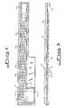
- Fig. 1 is an exploded, isometric view of an inoculator and test panel assembly according to the invention;
- Fig. 2 is a top plan view of the inoculator shown in Fig. 1;
- Fig. 3 is a side elevation view of the inoculator shown in Figs. 1 and 2;
- Fig. 4 is a sectional view of the inoculator test panel assembly in a first position with respect to each other;
- Fig. 5 is a sectional view of the inoculator/test panel assembly in a second position with respect to each other;
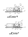
- Fig. 6 is a sectional view of an alternative embodiment of an inoculator according to the invention positioned above a test panel; and
- Fig. 7 is a sectional view thereof showing the inoculator engaging the test panel.
- An
assembly 10 for inoculating test sites with accurately reproducible, and optionally equal volumes of a suspension or other liquid sample is provided by the invention. The assembly includes aninoculator 12 and a test device which may be in the form of apanel 14 which is matched to the inoculator. A compressible member such as afoam gasket 16 is positioned between the inoculator 12 andtest panel 14, and separates them by an appropriate distance when the gasket is in the "relaxed" position. - The inoculator includes a generally trough-shaped
carrier 18 which is preferably of integral construction and molded from a polymeric material such as transparent polystyrene resin. It is important that the resin be of high purity and that no silicone release agents are used in the molding process. This is necessary to provide an inoculator having clean surfaces of controlled hydrophobicity, the importance of which shall be explained below. - The
carrier 18 has a base 20 including a substantially flatupper surface 22,peripheral side walls 24 projecting from theupper surface 22, and two rows ofcapillaries 26. The base and side walls define a reservoir or trough. Each of the capillaries extends through the base and includes an upper opening adjoining theupper surface 22 of the carrier base and in fluid communication with the reservoir. Filling of the capillaries is facilitated if they are substantially tangent to theside walls 24. - Two rows of
projections 28 extend from the lower surface of thecarrier base 20. Each projection includes atapered end 30 adjoining the bottom opening of each capillary. These tapered ends of the projections, which with thecarrier base 20 and projections define the walls of therespective capillaries 26, are useful in maintaining liquid within the capillaries. While flat-bottomed projections or even no projections could be employed, liquid would be encouraged to run through the capillaries and form hanging drops on the respective flat, bottom surfaces. The preferred tapered ends require the liquid to run back up each bevelled edge, something which is not likely to occur. A second advantage of the tapered projection ends is that they increase the likelihood of the capillaries properly contacting test sites with which they may be brought into engagement, a process described in greater detail below. It is important that the bottom surfaces of the tips of the projections not be significantly more wettable than the inner walls of the capillaries as the inoculum may run through the capillaries, thereby potentially contaminating the work area or the test sites. - The capillaries in a single inoculator may have the same or different volumes ranging between about one to twenty-five microliters each. The
inoculator 12 shown in Figs. 1-5 is designed to inoculate sixty-four disk-shapedsupports 32 with equal volumes of a liquid or suspension. (The terms liquid and suspension are used interchangeably herein). The supports may be in the form of absorbent disks, hydrophilic membranes, or other substrates depending upon the tests which are to be conducted. Microwells may also be inoculated with liquid from the respective capillaries. Each capillary includes taperedinterior walls 34 tapering from about a 0.055" (0.140 cm) diameter at theupper surface 22 of the carrier base to about a 0.040" (0.102 cm) diameter at the open end of eachprojection 28. The length of each capillary is about 0.12" (0.30 cm), and the volume thereof is accordingly about 3.5 microliters. - The capillaries of the
inoculator 12 used in accordance with the preferred embodiment of the invention are provided with such tapered, preferably conicalinterior walls 34 to facilitate the process of molding the inoculator. A long, thin core pin on the scale of the capillary cannot be pulled out of the molded part without damage thereto and erosion of the pin unless it has a draft angle. Although it is not required in theinoculator 12 shown and described herein, a capillary which is larger at the top than at the bottom will reliably hold a greater volume of liquid than one which is of uniform diameter. The range of acceptable capillary diameters depends on the material properties of the capillaries and the liquid held therein, the acceleration range over which the capillaries are expected to retain the liquid by surface forces, the method by which the inoculator is filled with liquid, and the method used for removing liquid from the inoculator. In the preferred embodiment of the invention, the liquid is removed from each capillary 26 by wicking into a small absorbent support containing the reagents with which the liquid is to react. Using this removal process, the minimum diameter of the bottom of the capillary must be a few times larger than the effective pore size of the absorbent support. For a particular support as described below, this would permit a minimum diameter of 0.001 inch (0.00254 cm). Such a small diameter is, however, very difficult to mold and would unduly slow the desired removal of the liquid. The liquid might, in other applications, be removed by applying pressurized air or other pressurized gas to the top of the capillaries, or by deliberate acceleration of the liquid-filled device. With these removal methods there are no definite lower limits to the capillary diameter except the limits imposed by the method of manufacture of the device and the required speed of liquid removal. - The maximum diameter of the bottom of each capillary 26 is determined by the need to retain the liquid in the capillary during the accelerations associated with any desired or likely motions of the
inoculator 12 between the time thecapillaries 26 are filled and the time the removal of the liquid is desired. The resulting inertial forces must be overcome by the surface tension forces at the surface of the liquid. In the preferred embodiment of the invention, an aqueous liquid containing a low concentration of wetting agent is held in polystyrene capillaries, each of which has a length a few times (i.e. 2-4) its average diameter. Manual manipulation of the filled device is required to expel the liquid. The practical upper limit of the diameter of each capillary is about 0.1 inch (0.254 cm). With more gentle motion of the inoculator, a more wettable capillary material, and a liquid of higher surface tension, a larger diameter could be used. These maximum diameters depend also on the length of the capillary and the direction and magnitude of the acceleration. The force of gravity is generally the minimum force which must be resisted. - The maximum diameter of the top, or liquid entrance end, of the capillaries is limited by the volumetric accuracy desired when the capillaries are filled by flowing a liquid across them, which is the preferred filling method employed for the inoculator disclosed herein. If the diameter becomes too large, volumetric accuracy suffers due to the variation in the liquid surface shapes left as the flowing liquid breaks away from that liquid which is retained in the particular capillary.
- The capillaries may, if desired, be filled from the bottom by capillary rise. The projections are immersed in a liquid for a sufficient time to allow the capillaries to completely fill. The capillaries are preferably simultaneously filled. In this case, the maximum diameter of the top (and all other portions of each capillary) is imposed by the requirement that the surface tension of the liquid, its contact angle with the material of the capillary, and the diameter ensure that each capillary is filled to the top. Volumetric accuracy is thereby provided.
- A transparent polystyrene carrier as employed herein, used in conjunction with microbiological suspensions for inoculating absorbent supports, functions successfully where each capillary has a volume between three and ten microliters. Using different materials and/or design parameters, capillary volumes ranging from 1-25 microliters could be employed. Generally speaking, the capillaries are designed so that the volume of liquid retained by each is the same upon filling and remains the same for up to ten minutes before transfer without accidental release or significant evaporation. Using the parameters described above, these objects can be successfully attained.
- Referring to Figs. 1, 2 and 4, the
inoculator 12 includes a carrier designed as a long, narrow trough having anelongate center ridge 36 which separates the two rows ofcapillaries 26. (Theridge 36 should be omitted if it causes difficulty in filling the capillaries). Afill area 38 which is devoid of capillaries is provided at one end of the carrier. Thefill area 38 includes an inclinedupper surface 40 which adjoins theupper surface 22 of thecarrier base 20 at one end and adjoins theperipheral side walls 24 at three surfaces thereof. Liquid deposited on theupper surface 40 of the fill area accordingly tends to move toward theupper surface 22 of thecarrier base 20 which includes the upper openings of thecapillaries 26. - An
excess inoculum trap 42 is integrally formed with thecarrier base 20 in offset relation to the remainder of the reservoir. Asecond ridge 44 including aninclined surface 46 adjoining the main reservoir portion separates this reservoir portion from thetrap 42. Asponge 48 or other absorbent material is positioned within the trap. Any absorbent material may be employed in the trap as long as it does not release any dust or fiber debris into the capillary area and it is not affected by the inoculum. - A pair of laterally extending
flanges 50 project from each side of thecarrier base 20. One of the flanges includes a relativelylarge area 52 which may be used for gripping the inoculator and/or applying an identification label thereto. - A plurality of
feet 54 project downwardly from the bottom surface of thecarrier 18. The feet serve to raise the capillary tips out of contact with the work surface and to act as locators to align the inoculator with the test panel if it is attached to a panel as described later. - A
transparent cover tape 56 made from adhesive-backed clear MYLAR or any other liquid-impervious material is secured to the upper edges of theperipheral wall 24 of thecarrier 18. The tape covers all portions of the carrier with the exception of thefill area 38. - The structure and configuration of the device to be inoculated by the
inoculator 12 according to the invention depends upon the particular application of the device. Several such devices are disclosed in commonly assigned U.S. Application Serial Number 209,677 filed June 20, 1988 and entitled "Device For Enhancing Fluorescence And Kinetics And Methods Of Using The Device", which is incorporated by reference herein. - The
test panel 14 as shown in the figures is molded from polypropylene or other suitable polymeric material. As shown in Figs. 1 and 4, it includes a substantially flat,rectangular body 58 including anelongate ridge 60 which has a flatupper surface 62. Sixty-fourcylindrical test wells 64, each having an upper opening adjoining theupper surface 62 of theelongate ridge 60 and a lower opening adjoining thebottom surface 66 of the test panel, are provided. Each well has a larger diameter than the diameter of theprojections 28 extending from the inoculator. The depth of thewells 64 is less than the length of these projections. Optionalposition reference notches 68 are provided in the longitudinal edge of the test panel nearest the wells, each notch being aligned with one of the respective wells. Apanel data label 70 may be applied to the upper surface of the panel. - A transparent, liquid-
impermeable adhesive tape 72 is secured to thebottom surface 66 of thetest panel 14. The tape may be an acrylic, adhesive-backed strip of clear MYLAR or other suitable polymeric material. As shown in Fig. 4, thetape 72 is secured to thebottom surface 66 of thetest panel 14. Thetape 72 provides an adhesive bottom for each of thecylindrical wells 64. The disks ormembranes 32 are secured, respectively, to the adhesive bottoms of thecylindrical wells 64, and comprise the test sites at which test data is obtained. - A
notch 72 is provided within one of the ends of thetest panel 14 for receiving one of thefeet 54 extending from theinoculator 12. Twoopenings 74 are formed near the opposite end of thetest panel 14 for receiving the other twofeet 54 of the inoculator. The test panel itself may include a plurality offeet 76 for facilitating the handling thereof, positioning it within a test instrument, and protecting thetransparent tape 72. Avent channel 78 extends between the end of theelongate ridge 60 and an edge of the test panel. - The disk-shaped
supports 32 within each cylindrical test well 64 are preferably made from an absorbent material such as alpha cellulose or pH neutralized glass fiber. Alpha cellulose in the form of cotton lint paper is particularly preferred. The thickness of the disks should be sufficient to carry an effective amount of reagent for reaction with the particular liquid inoculant. In general, a thickness of from 0.2mm to 2.0mm has been found suitable where the supports have been pieces of filter paper. In such cases, a solution of test reagent is absorbed by the supports and dried prior to their receiving the liquid inoculum from theinoculator 12. A support thickness of 0.5mm to 0.9mm is generally preferred for such analyses. - The shape of the support within each test well 64 is not critical. The thickness thereof, in cooperation with the surface area, determines the volume of liquid required to completely wet each support. The void volume of each support is preferably between about one microliter and twenty-five microliters.
- In operation, the liquid inoculum is introduced into the reservoir of the
carrier 18 by pouring or pipetting it into thefill area 38. A desirable feature of the invention is that the sample volume introduced to the inoculator can vary over a wide range, e.g. 300-1000 microliters, with no effect upon the accuracy of the volumes deposited upon the test sites. - The liquid inoculum deposited within the carrier generally will not have a sufficient volume to cover all of the capillaries simultaneously upon introduction. Due to the hydrophobic surfaces which define the reservoir, the liquid inoculant tends to form a rolling mass covering only about one quarter of the capillaries. Additional liquid is not necessary, however, thereby avoiding the wasting of inoculum. After depositing the total volume of liquid inoculum in the
fill area 38, the operator tilts theinoculator 12 slightly towards the trap end to move this mass of liquid sequentially over the top ends of the capillaries, filling each as it is covered. Filling takes place partially by gravity flow, but primarily through capillary action. The dual trough defined by theside walls 24 andelongate ridge 36 is narrow enough that each capillary must be filled as the liquid passes over it. If no ridge is employed, the distance between the side walls should be sufficiently small such that the liquid engages each capillary. Once all of the capillaries are filled and the excess liquid is situated at the trap end, the inoculator is tilted about its longitudinal axis towards thetrap 42 itself by 30-40° to flow the liquid over theridge 44 and into thetrap sponge 48. The hydrophobic surfaces of the carrier retain essentially no liquid in the channels above the capillaries. Thecover tape 56 helps prevent spillage. - The liquid deposited within the
capillary inoculator 12 should preferably contain a visible dye to provide confirmation that all capillaries are completely filled. When viewed from the top of thecarrier 18, the capillary cavities are relatively long and narrow. A small amount of dye is accordingly easily discernible; a partially filled capillary will be visibly lighter in color. - Alternatively, by selecting a liquid having the same refractive index as the plastic from which the capillaries are made, the need for using a dye may be obviated. Instead of looking for a relatively dark column of liquid to verify that each capillary is filled, the bore of the capillary would appear to vanish when it is filled.
- The
inoculator 12 is preferably, though not essentially, mounted to thetest panel 14 prior to filling. Thefoam gasket 16 or other resilient separating means between the inoculator and test panel should be stiff enough to prevent contact between theprojections 28 and the disk-shapedsupports 32 during normal handling. In addition, the capillaries themselves should be of appropriate size and configuration that no liquid is jarred loose during normal handling, including turning the inoculator on end or upside down. - Liquid transfer from the
inoculator 12 to the test sites within thetest panel 14 is preferably machine initiated. A self-aligning plate (not shown) is pressed down on top of the inoculator, forcing the tips of the capillaries into contact with thesupports 32, as shown in Fig. 5. The liquid quickly and substantially simultaneously wicks out of the capillaries upon such contact if the supports are sufficiently absorbent. While the same procedure could be accomplished manually, it is important for many applications that instrument readings be taken immediately after inoculation. Repeatable tests could not be consistently performed through manually initiated inoculation. As discussed above, inoculation could also be accomplished through the use of gas pressure above the capillaries or by sudden acceleration of the inoculator. - Depending upon what reactive substrate is incorporated within each
support 32, the appropriate tests may be conducted subsequent to inoculation. Reactions between the inoculum and substrate may in some cases be visually observed. Since the liquid does not readily evaporate from the capillaries, it is not critical that inoculation of the test sites be accomplished immediately after filling. Thefoam gasket 16 protects the capillary tips from any air flow while thecover tape 56 protects the upper openings of the capillaries. Evaporation is accordingly minimized. - Instrument readings are taken with the inoculator in the position shown in Fig. 4. Alternatively, the inoculator may be removed from the test panel and discarded.
- If desired, the
sponge 48 or other absorbent material placed within the inoculator may include a reagent dried thereon. When excess inoculum is run off into the trap, a large volume of analyte is brought into contact with the reagent. A visible color change or fluorescent reaction may be used to indicate a positive result. The procedure may be used for tests which require a relatively large volume, but not a precise volume which is in contrast to the tests conducted at the test sites within thetest panel 14 which require small, precise samples. - The
inoculator 12 and the method of inoculation described above provide a number of significant advantages where small, precise quantities of liquid inoculum must be deposited upon test sites. Since no pressure or suction is required for inoculum transfer, errors associated with the compressibility of air are avoided. The filling of the inoculator in a single pipetting step or pour operation does not require high position or volume accuracy. The inoculum is divided into a number of precise volumes in a single operation. The individual volumes of inoculum are isolated from each other, thereby precluding cross-contamination when the inoculum is transferred to the test sites. Excess inoculum is trapped within the inoculator, thereby preventing spillage, accidental contact, and errors in the amount of inoculum transferred to each test site. By using the inoculator in the described manner, good accuracy and repeatability can be obtained even when simultaneously inoculating test sites with volumes of five microliters or less. The inoculator allows one to visibly determine whether the capillaries have been correctly filled, and insures that evaporation does not significantly affect the liquid within the capillaries in the normal period between capillary filling and inoculation. Liquid is retained within the capillaries regardless of the orientation of the inoculator. - An alternative embodiment of the invention is shown in Figs. 6-7. The assembly 10' shown therein is generally the same in structure and function as that shown in Figs. 1-5, but is preferred for handling relatively small volumes of liquid.
- The assembly includes an elongated inoculator 12' and a test device 14' matched thereto. The inoculator 12' may be engaged to the test device 14' by means of conventional interlocking snaps (not shown) formed integrally within the respective components. A pair of resilient buttons 16' positioned between the inoculator 12' and test device 14' on opposite ends of the assembly 10' maintain the inoculator 12' in the raised position shown in Fig. 6. Only one of the buttons is shown in Fig. 6.
- The use of the buttons 16' in place of a
foam gasket 16 allows air to move through the assembly. In order to minimize evaporation losses, the inoculator 12' is accordingly formed with wall members 17' which fit within a substantially oval groove 19' surrounding the test wells 64' within the test device 14'. The relative positions of these wall members 17' and the outer walls 21' of the test wells 64' impede the flow of air across the bottoms of the capillaires 26', thereby reducing the evaportion which would otherwise occur. - The inoculator 12' includes a carrier 18' including a flat upper surface 22' and peripheral side walls 24' projecting from the flat upper surface. The capillaries 26' are substantially tangent to the side walls to facilitate the entry of liquid. No ridge is provided between the rows of capillaries. A flange 52' similar in structure and function to the
flange 52 of the embodiment shown in Figs. 1-5 is also provided. - The test device 14' is similar in structure to the above-referenced embodiment with certain exceptions as noted above. In addition, the disk-shaped supports 32' are adhered to the bottom surface of the test device itself rather than to the
tape 72 disclosed above. Filling of the inoculator 12' and inoculation of the test sites is accomplished in substantially the same manner discussed above with respect to the first-describedinoculator 12. The inoculator 12' is filled while in the position shown in Fig. 6, while inoculation takes place when it is moved to the position shown in Fig. 7. Substantially all of the liquid within each capillary 26' is dispensed as the projections 28' contact the absorbent test sites. - Although illustrative embodiments of the present invention have been described herein with reference to the accompanying drawings, it is to be understood that the invention is not limited to those precise embodiments, and that various other changes and modifications may be effected therein by one skilled in the art without departing from the scope or spirit of the invention.
Claims (12)
- A capillary inoculator for dividing a liquid inoculant into a plurality of volumes and inoculating a plurality of test sites, comprising:
a carrier including a base, side walls projecting upwardly from said base and optionally, a cover secured to said side walls of said carrier, said base and side walls defining a reservoir; and
a plurality of capillaries in fluid communication with said reservoir and extending, respectively, through said base, each of said capillaries capable of retaining a liquid inoculant therein subject to at least the force of gravity by means of surface tension and adhesion. - A capillary inoculator as defined in Claim 1 wherein said base and said side walls define an elongate reservoir including a pair of opposing ends, an overflow trap, and which includes a means for separating said reservoir from said overflow trap.
- A capillary inoculator for inoculating a plurality of test sites, comprising:
a carrier;
a plurality of projections extending from said carrier; and
a plurality of capillaries extending through said projections, each of said capillaries capable of retaining a liquid inoculant therein subject to at least the force of gravity by means of surface tension and adhesion, and each of said capillaries including a pair of open ends so that they may be filled by capillary action. - A capillary inoculator as defined in Claim 3 wherein each of said projections includes a tapered bottom end.
- An assembly for simultaneously inoculating a plurality of discrete test sites, comprising;
an inoculator including a carrier and a plurality of capillaries extending through said carrier, each of said capillaries being capable of retaining a liquid inoculant therein by surface tension and adhesion sufficient to overcome at least the force of gravity, each of said capillaries including a discharge end; and
a device arranged in adjoining relation to said inoculator for receiving liquid inoculant from said inoculator, said device including a plurality of discrete test sites, each of said discharge ends of said capillaries being in registry, respectively, with said test sites. - An assembly as defined in Claim 5 including a compressible member positioned between said inoculator and said device, said discharge ends of said capillaries being positioned such that they respectively contact said test sites when said inoculator is moved a selected distance towards said device, said compressible member being compressed when said inoculator has been moved said selected distance towards said device.
- An assembly as defined in Claim 5 wherein said carrier defines a reservoir in fluid communication with said capillaries.
- An assembly as defined in Claim 5 wherein said test sites are defined by a plurality of test wells within said device, and which optionally includes a plurality of absorbent supports positioned, respectively, within said test wells.
- A method of simultaneously inoculating a plurality of test sites with a liquid inoculum comprising the steps of:
providing an inoculator including a carrier having a plurality of capillaries extending therethrough, each of said capillaries including a discharge end;
providing a liquid inoculum within each of said capillaries, said liquid inoculum being retained within each of said capillaries by surface tension and adhesion sufficient to overcome the force of gravity;
providing a test device including a plurality of test sites, optionally containing an absorbent support therein;
aligning said capillaries with said respective test sites; and
causing said liquid inoculum within each of said capillaries to be transferred to said respective test sites. - A method as defined in Claim 9 including the steps of providing a compressible member between said inoculator and said test device, and urging said inoculator towards said test device, thereby compressing said compressible member and causing said discharge ends of said capillaries to contact said respective test sites.
- A method of providing a plurality of discrete liquid samples having small, precise volumes, comprising:
providing a liquid within said reservoir; and
causing said liquid to contact each of said capillaries for a sufficient length of time to substantially completely fill said capillaries by capillary action or a combination of gravity and capillary action. - A method of providing a plurality of discrete liquid samples having small precise volumes, comprising:
providing a carrier including a plurality of projections extending therefrom and a plurality of capillaries extending, respectively, through said projections; and
immersing said projections within a liquid for a sufficient time for said capillaries to substantially completely fill with said liquid by capillary action.
Applications Claiming Priority (2)
| Application Number | Priority Date | Filing Date | Title |
|---|---|---|---|
| US52980290A | 1990-05-29 | 1990-05-29 | |
| US529802 | 1990-05-29 |
Publications (3)
| Publication Number | Publication Date |
|---|---|
| EP0459093A2 true EP0459093A2 (en) | 1991-12-04 |
| EP0459093A3 EP0459093A3 (en) | 1992-12-02 |
| EP0459093B1 EP0459093B1 (en) | 1996-05-22 |
Family
ID=24111290
Family Applications (1)
| Application Number | Title | Priority Date | Filing Date |
|---|---|---|---|
| EP91103353A Expired - Lifetime EP0459093B1 (en) | 1990-05-29 | 1991-03-22 | Capillary inoculator and assembly for inoculating multiple test sites and method of inoculating test sites therewith. |
Country Status (11)
| Country | Link |
|---|---|
| EP (1) | EP0459093B1 (en) |
| JP (1) | JPH0867B2 (en) |
| AT (1) | ATE138412T1 (en) |
| AU (1) | AU646242B2 (en) |
| CA (1) | CA2040920C (en) |
| DE (1) | DE69119647T2 (en) |
| FI (1) | FI101324B1 (en) |
| IE (1) | IE75386B1 (en) |
| MY (1) | MY109607A (en) |
| NO (1) | NO911083L (en) |
| NZ (1) | NZ237521A (en) |
Cited By (11)
| Publication number | Priority date | Publication date | Assignee | Title |
|---|---|---|---|---|
| EP0635710A2 (en) * | 1993-07-21 | 1995-01-25 | Johnson & Johnson Clinical Diagnostics, Inc. | Method and apparatus for surface area liquid transfer |
| EP0635712A2 (en) * | 1993-07-21 | 1995-01-25 | Johnson & Johnson Clinical Diagnostics, Inc. | Method of pretreating diagnostic test elements |
| EP0795600A1 (en) * | 1994-12-22 | 1997-09-17 | Showa Yakuhin Kako Co., Ltd. | Device for chemical and microbiological tests |
| WO1998028441A1 (en) * | 1996-12-23 | 1998-07-02 | bioMérieux Vitek, Inc. | Air matrix material for chemical reactions |
| WO1999022017A2 (en) * | 1997-10-27 | 1999-05-06 | Idexx Laboratories, Inc. | Device and methods for determination of analyte in a solution |
| WO2000042430A1 (en) * | 1999-01-15 | 2000-07-20 | Medtox Scientific, Inc. | Lateral flow test strip |
| WO2000053721A1 (en) * | 1999-03-09 | 2000-09-14 | 3M Innovative Properties Company | Disc assay device with inoculation pad and methods of use |
| EP1153285A1 (en) * | 1999-01-21 | 2001-11-14 | Caliper Technologies Corporation | Method and apparatus for continuous liquid flow in microscale channels using pressure injection, wicking, and electrokinetic injection |
| US6391578B2 (en) | 1997-04-09 | 2002-05-21 | 3M Innovative Properties Company | Method and devices for partitioning biological sample liquids into microvolumes |
| US6696286B1 (en) | 1997-04-09 | 2004-02-24 | 3M Innovative Properties Company | Method and devices for detecting and enumerating microorganisms |
| WO2004081530A2 (en) * | 2003-03-10 | 2004-09-23 | The Johns Hopkins University | Method and apparatus for environmental monitoring and bioprospecting |
Families Citing this family (3)
| Publication number | Priority date | Publication date | Assignee | Title |
|---|---|---|---|---|
| US5955352A (en) * | 1994-12-22 | 1999-09-21 | Showa Yakuhin Kako Co., Ltd. | Instruments for chemical and microbiological tests |
| JP4566509B2 (en) * | 2001-12-28 | 2010-10-20 | 株式会社エンプラス | Plastic plate and plastic plate assembly |
| JP5698900B2 (en) * | 2009-03-19 | 2015-04-08 | テルモ株式会社 | Cell culture transfer device |
Citations (3)
| Publication number | Priority date | Publication date | Assignee | Title |
|---|---|---|---|---|
| GB1552128A (en) * | 1975-06-28 | 1979-09-05 | Square D Co | Computer based control systems including a protection circuit |
| GB1572596A (en) * | 1976-12-06 | 1980-07-30 | Opto Electronic Displays Ltd | Apparatus and method for innoculation |
| US4699884A (en) * | 1984-02-29 | 1987-10-13 | Gerhard Noss | Process and apparatus for the simultaneous application of a multiplicity of liquid samples to an object stage |
-
1991
- 1991-03-11 AU AU72803/91A patent/AU646242B2/en not_active Ceased
- 1991-03-13 MY MYPI91000406A patent/MY109607A/en unknown
- 1991-03-19 NO NO91911083A patent/NO911083L/en unknown
- 1991-03-20 IE IE93191A patent/IE75386B1/en not_active IP Right Cessation
- 1991-03-20 NZ NZ237521A patent/NZ237521A/en unknown
- 1991-03-22 DE DE69119647T patent/DE69119647T2/en not_active Expired - Fee Related
- 1991-03-22 EP EP91103353A patent/EP0459093B1/en not_active Expired - Lifetime
- 1991-03-22 AT AT91103353T patent/ATE138412T1/en not_active IP Right Cessation
- 1991-04-22 CA CA002040920A patent/CA2040920C/en not_active Expired - Fee Related
- 1991-05-28 FI FI912558A patent/FI101324B1/en active IP Right Grant
- 1991-05-29 JP JP3125812A patent/JPH0867B2/en not_active Expired - Lifetime
Patent Citations (3)
| Publication number | Priority date | Publication date | Assignee | Title |
|---|---|---|---|---|
| GB1552128A (en) * | 1975-06-28 | 1979-09-05 | Square D Co | Computer based control systems including a protection circuit |
| GB1572596A (en) * | 1976-12-06 | 1980-07-30 | Opto Electronic Displays Ltd | Apparatus and method for innoculation |
| US4699884A (en) * | 1984-02-29 | 1987-10-13 | Gerhard Noss | Process and apparatus for the simultaneous application of a multiplicity of liquid samples to an object stage |
Cited By (26)
| Publication number | Priority date | Publication date | Assignee | Title |
|---|---|---|---|---|
| EP0635712A2 (en) * | 1993-07-21 | 1995-01-25 | Johnson & Johnson Clinical Diagnostics, Inc. | Method of pretreating diagnostic test elements |
| EP0635712A3 (en) * | 1993-07-21 | 1995-04-19 | Eastman Kodak Co | Method of pretreating diagnostic test elements. |
| EP0635710A3 (en) * | 1993-07-21 | 1995-04-19 | Eastman Kodak Co | Method and apparatus for surface area liquid transfer. |
| US5895761A (en) * | 1993-07-21 | 1999-04-20 | Clinical Diagnostic Systems, Inc. | Surface area liquid transfer method and related apparatus |
| EP0635710A2 (en) * | 1993-07-21 | 1995-01-25 | Johnson & Johnson Clinical Diagnostics, Inc. | Method and apparatus for surface area liquid transfer |
| EP0795600A1 (en) * | 1994-12-22 | 1997-09-17 | Showa Yakuhin Kako Co., Ltd. | Device for chemical and microbiological tests |
| US6103503A (en) * | 1996-12-23 | 2000-08-15 | Bio Merieux, Inc. | Method and apparatus for carrying out nucleic acid amplification reactions within a porous absorbent material |
| WO1998028441A1 (en) * | 1996-12-23 | 1998-07-02 | bioMérieux Vitek, Inc. | Air matrix material for chemical reactions |
| US6696286B1 (en) | 1997-04-09 | 2004-02-24 | 3M Innovative Properties Company | Method and devices for detecting and enumerating microorganisms |
| US6391578B2 (en) | 1997-04-09 | 2002-05-21 | 3M Innovative Properties Company | Method and devices for partitioning biological sample liquids into microvolumes |
| WO1999022017A3 (en) * | 1997-10-27 | 1999-08-05 | Idexx Lab Inc | Device and methods for determination of analyte in a solution |
| WO1999021655A1 (en) * | 1997-10-27 | 1999-05-06 | Idexx Laboratories, Inc. | Device and methods for determination of analyte in a solution |
| WO1999022017A2 (en) * | 1997-10-27 | 1999-05-06 | Idexx Laboratories, Inc. | Device and methods for determination of analyte in a solution |
| US6190878B1 (en) * | 1997-10-27 | 2001-02-20 | Idexx Laboratories, Inc. | Device and methods for determination of analyte in a solution |
| AU736154B2 (en) * | 1997-10-27 | 2001-07-26 | Idexx Laboratories, Inc. | Device and methods for determination of analyte in a solution |
| US6268209B1 (en) | 1997-10-27 | 2001-07-31 | Idexx Laboratories, Inc. | Device and method for determination of analyte in a solution |
| WO2000042430A1 (en) * | 1999-01-15 | 2000-07-20 | Medtox Scientific, Inc. | Lateral flow test strip |
| US6566051B1 (en) | 1999-01-15 | 2003-05-20 | Medtox Scientific, Inc. | Lateral flow test strip |
| EP1153285A1 (en) * | 1999-01-21 | 2001-11-14 | Caliper Technologies Corporation | Method and apparatus for continuous liquid flow in microscale channels using pressure injection, wicking, and electrokinetic injection |
| EP1153285A4 (en) * | 1999-01-21 | 2002-07-31 | Caliper Techn Corp | Method and apparatus for continuous liquid flow in microscale channels using pressure injection, wicking, and electrokinetic injection |
| US6291202B1 (en) | 1999-03-09 | 2001-09-18 | 3M Innovative Properties Company | Disc assay device with inoculation pad and methods of use |
| US6174699B1 (en) | 1999-03-09 | 2001-01-16 | 3M Innovative Properties Company | Disc assay device with inoculation pad and methods of use |
| AU764361B2 (en) * | 1999-03-09 | 2003-08-14 | 3M Innovative Properties Company | Disc assay device with inoculation pad and methods of use |
| WO2000053721A1 (en) * | 1999-03-09 | 2000-09-14 | 3M Innovative Properties Company | Disc assay device with inoculation pad and methods of use |
| WO2004081530A2 (en) * | 2003-03-10 | 2004-09-23 | The Johns Hopkins University | Method and apparatus for environmental monitoring and bioprospecting |
| WO2004081530A3 (en) * | 2003-03-10 | 2005-01-27 | Univ Johns Hopkins | Method and apparatus for environmental monitoring and bioprospecting |
Also Published As
| Publication number | Publication date |
|---|---|
| EP0459093B1 (en) | 1996-05-22 |
| JPH0867B2 (en) | 1996-01-10 |
| CA2040920A1 (en) | 1991-11-30 |
| JPH04228062A (en) | 1992-08-18 |
| EP0459093A3 (en) | 1992-12-02 |
| FI912558A (en) | 1991-11-30 |
| IE910931A1 (en) | 1991-12-04 |
| DE69119647T2 (en) | 1996-12-05 |
| NO911083L (en) | 1991-12-02 |
| AU646242B2 (en) | 1994-02-17 |
| NO911083D0 (en) | 1991-03-19 |
| IE75386B1 (en) | 1997-09-10 |
| MY109607A (en) | 1997-03-31 |
| CA2040920C (en) | 1995-05-23 |
| FI101324B (en) | 1998-05-29 |
| AU7280391A (en) | 1991-12-05 |
| ATE138412T1 (en) | 1996-06-15 |
| FI912558A0 (en) | 1991-05-28 |
| FI101324B1 (en) | 1998-05-29 |
| NZ237521A (en) | 1994-03-25 |
| DE69119647D1 (en) | 1996-06-27 |
Similar Documents
| Publication | Publication Date | Title |
|---|---|---|
| US5100620A (en) | Capillary tube/gap reagent format | |
| EP0459093B1 (en) | Capillary inoculator and assembly for inoculating multiple test sites and method of inoculating test sites therewith. | |
| US4308028A (en) | Device and method for the chemical testing and microscopic examination of liquid specimens | |
| US4501496A (en) | Specimen slide for analysis of liquid specimens | |
| US6566051B1 (en) | Lateral flow test strip | |
| EP1377831B1 (en) | Multiple analyte assaying device with a multiple sample introduction system | |
| US5338666A (en) | Method for distributing a liquid sample into a multiple aliquot device | |
| US4790640A (en) | Laboratory slide | |
| US4589421A (en) | Sampling device | |
| JP2003139772A (en) | Instrument for measuring concentration in specimen, manufacturing method therefor, and method for using the same | |
| US5091153A (en) | Chemical analysis test device | |
| EP1886177B1 (en) | Counting, viability assessment, analysis and manipulation chamber | |
| AU2358299A (en) | Process for the production of analytical devices | |
| JPH04232855A (en) | Self-measuring-type fluid analyzing tool | |
| US20190381499A1 (en) | Blood metering device with desiccant and support for storage media and inlay with flange | |
| US5173433A (en) | Method for chemical analysis | |
| EP2994761B1 (en) | Imaging cartridge, pipette, and method of use for direct sputum smear microscopy | |
| AU703875B2 (en) | Device for optical analysis of specimens | |
| US20040184965A1 (en) | Testing cup | |
| US6555386B1 (en) | Apparatus for collecting a liquid sample | |
| US20050053519A1 (en) | Delta cup | |
| EP2094388A1 (en) | A well plate for holding a sample during analysis and a method for preparing a sample for analysis | |
| US5401467A (en) | Whole blood metering cup | |
| GB2051359A (en) | A sample or reagent container for automatic analysis apparatus | |
| JP2023162456A (en) | Liquid sampling tool, method for manufacturing the same, and test kit |
Legal Events
| Date | Code | Title | Description |
|---|---|---|---|
| PUAI | Public reference made under article 153(3) epc to a published international application that has entered the european phase |
Free format text: ORIGINAL CODE: 0009012 |
|
| AK | Designated contracting states |
Kind code of ref document: A2 Designated state(s): AT BE CH DE DK ES FR GB GR IT LI LU NL SE |
|
| PUAL | Search report despatched |
Free format text: ORIGINAL CODE: 0009013 |
|
| AK | Designated contracting states |
Kind code of ref document: A3 Designated state(s): AT BE CH DE DK ES FR GB GR IT LI LU NL SE |
|
| 17P | Request for examination filed |
Effective date: 19930210 |
|
| 17Q | First examination report despatched |
Effective date: 19941229 |
|
| GRAH | Despatch of communication of intention to grant a patent |
Free format text: ORIGINAL CODE: EPIDOS IGRA |
|
| GRAA | (expected) grant |
Free format text: ORIGINAL CODE: 0009210 |
|
| AK | Designated contracting states |
Kind code of ref document: B1 Designated state(s): AT BE CH DE DK ES FR GB GR IT LI LU NL SE |
|
| PG25 | Lapsed in a contracting state [announced via postgrant information from national office to epo] |
Ref country code: NL Free format text: LAPSE BECAUSE OF FAILURE TO SUBMIT A TRANSLATION OF THE DESCRIPTION OR TO PAY THE FEE WITHIN THE PRESCRIBED TIME-LIMIT Effective date: 19960522 Ref country code: LI Effective date: 19960522 Ref country code: GR Free format text: LAPSE BECAUSE OF FAILURE TO SUBMIT A TRANSLATION OF THE DESCRIPTION OR TO PAY THE FEE WITHIN THE PRESCRIBED TIME-LIMIT Effective date: 19960522 Ref country code: ES Free format text: THE PATENT HAS BEEN ANNULLED BY A DECISION OF A NATIONAL AUTHORITY Effective date: 19960522 Ref country code: DK Effective date: 19960522 Ref country code: CH Effective date: 19960522 Ref country code: BE Effective date: 19960522 Ref country code: AT Effective date: 19960522 |
|
| REF | Corresponds to: |
Ref document number: 138412 Country of ref document: AT Date of ref document: 19960615 Kind code of ref document: T |
|
| REF | Corresponds to: |
Ref document number: 69119647 Country of ref document: DE Date of ref document: 19960627 |
|
| ET | Fr: translation filed | ||
| ITF | It: translation for a ep patent filed |
Owner name: ING. C. GREGORJ S.P.A. |
|
| PG25 | Lapsed in a contracting state [announced via postgrant information from national office to epo] |
Ref country code: SE Effective date: 19960822 |
|
| NLV1 | Nl: lapsed or annulled due to failure to fulfill the requirements of art. 29p and 29m of the patents act | ||
| REG | Reference to a national code |
Ref country code: CH Ref legal event code: PL |
|
| PG25 | Lapsed in a contracting state [announced via postgrant information from national office to epo] |
Ref country code: LU Free format text: LAPSE BECAUSE OF NON-PAYMENT OF DUE FEES Effective date: 19970331 |
|
| PLBE | No opposition filed within time limit |
Free format text: ORIGINAL CODE: 0009261 |
|
| STAA | Information on the status of an ep patent application or granted ep patent |
Free format text: STATUS: NO OPPOSITION FILED WITHIN TIME LIMIT |
|
| 26N | No opposition filed | ||
| PGFP | Annual fee paid to national office [announced via postgrant information from national office to epo] |
Ref country code: DE Payment date: 19991231 Year of fee payment: 10 |
|
| PGFP | Annual fee paid to national office [announced via postgrant information from national office to epo] |
Ref country code: FR Payment date: 20000310 Year of fee payment: 10 |
|
| PGFP | Annual fee paid to national office [announced via postgrant information from national office to epo] |
Ref country code: GB Payment date: 20000322 Year of fee payment: 10 |
|
| PG25 | Lapsed in a contracting state [announced via postgrant information from national office to epo] |
Ref country code: GB Free format text: LAPSE BECAUSE OF NON-PAYMENT OF DUE FEES Effective date: 20010322 |
|
| GBPC | Gb: european patent ceased through non-payment of renewal fee |
Effective date: 20010322 |
|
| PG25 | Lapsed in a contracting state [announced via postgrant information from national office to epo] |
Ref country code: FR Free format text: LAPSE BECAUSE OF NON-PAYMENT OF DUE FEES Effective date: 20011130 |
|
| REG | Reference to a national code |
Ref country code: FR Ref legal event code: ST |
|
| PG25 | Lapsed in a contracting state [announced via postgrant information from national office to epo] |
Ref country code: DE Free format text: LAPSE BECAUSE OF NON-PAYMENT OF DUE FEES Effective date: 20020101 |
|
| PG25 | Lapsed in a contracting state [announced via postgrant information from national office to epo] |
Ref country code: IT Free format text: LAPSE BECAUSE OF NON-PAYMENT OF DUE FEES;WARNING: LAPSES OF ITALIAN PATENTS WITH EFFECTIVE DATE BEFORE 2007 MAY HAVE OCCURRED AT ANY TIME BEFORE 2007. THE CORRECT EFFECTIVE DATE MAY BE DIFFERENT FROM THE ONE RECORDED. Effective date: 20050322 |