EP0460946A2 - Toy Facsimile - Google Patents
Toy Facsimile Download PDFInfo
- Publication number
- EP0460946A2 EP0460946A2 EP91305103A EP91305103A EP0460946A2 EP 0460946 A2 EP0460946 A2 EP 0460946A2 EP 91305103 A EP91305103 A EP 91305103A EP 91305103 A EP91305103 A EP 91305103A EP 0460946 A2 EP0460946 A2 EP 0460946A2
- Authority
- EP
- European Patent Office
- Prior art keywords
- case
- recording paper
- shaft
- speaker
- transfer roll
- Prior art date
- Legal status (The legal status is an assumption and is not a legal conclusion. Google has not performed a legal analysis and makes no representation as to the accuracy of the status listed.)
- Granted
Links
Images


Classifications
-
- A—HUMAN NECESSITIES
- A63—SPORTS; GAMES; AMUSEMENTS
- A63H—TOYS, e.g. TOPS, DOLLS, HOOPS OR BUILDING BLOCKS
- A63H33/00—Other toys
- A63H33/30—Imitations of miscellaneous apparatus not otherwise provided for, e.g. telephones, weighing-machines, cash-registers
Definitions
- the present invention relates to a toy which makes it possible to enjoy playing at the operation of a facsimile apparatus.
- Fig. 1 is a perspective view of the external appearance
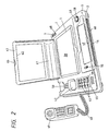
- Fig. 2 is a perspective view showing a state wherein a model handset is removed and a cover is opened
- Fig. 3 is an enlarged cross-section through the embodiment
- Fig. 4 is a plan view of the interior of a case main body
- Fig. 5 is a bottom plan view of the interior of a case cover body
- Fig. 6 is a plan view illustrating the construction of a paper transfer mechanism
- Fig. 7 is a side view illustrating the construction of the paper transfer mechanism.
- Numeral 1 denotes a case imitating the external appearance of a facsimile apparatus and molded from plastics, and comprising a case main body 2 and a case cover body 3.
- a pair of bearings 4, 4 spaced apart right and left are provided, and a take-up shaft 6 whereon recording paper 5 is rolled round is laid rotatably and removably on these bearings 4, 4, a spool 7 for rotating the take-up shaft 6 manually is joined removably to one end of the take-up shaft 6.
- a battery box 10 In the center inside the case main body 2, a battery box 10 is provided, having an opening 9 closable by a cover plate 8 provided in the base of the case main body 2.
- Two dry batteries 11, 11 are housed with the like poles thereof located on opposite sides.
- a paper transfer mechanism 14 comprising transfer rolls 13, 12 which hold, from above and below respectively, a fore-end part of recording paper 5 so drawn out from the take-up shaft 6 as to be inclined slightly downward, and on an upper side of a low front end wall 15 of the case main body 2, there is provided a delivery port 16 for delivering outside the case 1 the recording paper 5 transferred by the paper transfer mechanism 14.
- a ground plate 17 inclined gently so that it is in contact with a lower side of the recording paper 5 is provided.
- a guide plate 19 extends from the front end of said ground plate 17 to the delivery port 16 and is in contact with the lower side of the recording paper 5 and is inclined steeply so as to guide the recording paper 5 to the delivery port 16.
- the guide plate 19 has a cut part 18 formed so that part of the recording paper 15 may be held between the transfer rolls 12, 13, The front edge of said guide plate 19 is fixed to the case main body 2 by screws 20.
- the construction of the paper transfer mechanism 14 is such that a small-sized motor 22 and a rubber transfer roll 12 which is disposed to that it rotates in contact with the lower side of and in the direction of transfer of the recording paper 5 are provided inside a mechanism frame 21.
- the paper transfer mechanism 14 comprises the mechanism frame 21 which is provided with an electric motor 22 mounted on a shaft 23 and a rubber transfer roll 12 mounted on a shaft 31, the two shafts 23 and 31 being parallel and extending outside the mechanism frame 21.
- the paper transfer mechanism further comprises two additional shafts 26, 29 mounted in the mechanism frame and parallel to the motor shaft 23 and to the shaft 31.
- a first pinion gear 24 is fixed to one end of shaft 23 outside the mechanism frame 21, and a second pinion gear 25 is mounted on shaft 26 outside said mechanism frame to that it engages the first pinion gear 24.
- a third pinion gear 27 is mounted on shaft 26 inside the mechanism frame, and said third pinion gear engages a fourth pinion gear 28 mounted on shaft 29.
- a fifth pinion gear 30 is mounted on shaft 29, co-axial with gear 28, and this engages a sixth pinion gear 32 mounted on the shaft 31 of the rubber transfer roll 12.
- the rotation of the motor 22 is transmitted to the transfer roll 12 by the gears 24, 25, 27, 28, 30, 32, the speed of the rotation being reduced thereby.
- the transfer roll 13 comprises a plastic roll, which rotates in contact with the upper side of the recording paper 5 with the rotation of the transfer roll 12, disposed above and parallel to the transfer roll 12.
- the support shaft 31 of the transfer roll 12 is inserted through elongate holes 33 and 34 bored in the opposite side walls of the mechanism frame 21, while a spring 36 pressuring the support shaft 31 so that the shaft pushes up the transfer roll 12 to a position whereat it it always in contact with the transfer roll 13 and simultaneously pushes down the gear 32 to a position whereat it is always in contact with the pinion gear 30, is provided for suspension at one end 35 of the support shaft 31.
- the case cover body 3 is provided with: an opening 37 through which the take-up shaft 6 of the recording paper 5 may be carried in or out; an opening 39 cut in accordance with the width of a surface 38 of the recording paper 5 transferred onto the ground plate 17; a handset seat 42 whereon a model handset 41 connected to the lateral side of the case main body 2 by a spiral cord 40 is placed; an operation panel unit 45 which supports a push button group 43 comprising ten push buttons representing numerals 0 to 9 in imitation of push buttons of a push-button telephone set and a separate push button 44; an accommodation chamber 46 for accommodating writing materials and the like; a cover 47 for this accommodation chamber 46; and a hole 48 cut so that a part of the outer circumference of the spool 7 projects therethrough.
- a hole 59 is cut in the case cover body to that a push button 58 for operating a motor switch 57 connected between the dry batteries 11, 11 and the motor 22 by lead wires 56 inside the case main body 2 projects therethrough.
- a saw-toothed edge 60 for cutting the recording paper 5 is fixed to that part of the front end of the case cover body 3 which faces the exit of the delivery port 16.
- the case cover body 3 is put on the case main body 2 and fixed integrally to the case main body 2 by driving screws through several joining holes 66 provided in the case main body 2 into corresponding joining holes 67 provided in the case cover body 3.
- a cover 63 having a cover part 61 with which the opening 37 is covered and a window frame part 62 surrounding the surface 38 of the recording paper 5 to expose a prescribed area thereof on the cut opening 39 is provided on the case cover body 3.
- a part 64 is provided at the rear end of said cover 63 and is fitted pivotally to the rear end of the case cover body 3 so that the cover can be opened and closed, while a grip part 65 is provided at a front end of the cover 63.
- the power switch 55 is turned ON and a character, a picture or the like is written or drawn on the surface 38 of the recording paper 5 exposed within the window frame part 62 of the cover 63.
- the copy thus prepared is handled at if it were set in the facsimile apparatus at an original copy to be transmitted, and the push buttons of the push button group 43 are pushed in imitation of an operation of calling up the facsimile number of the person to whom the transmission made, or the push button group 43 is operated, with the model handset 41 picked up from the handset seat 42 and held to the ear, in imitation of making a telephone call.
- the cover 63 When the recording paper is used up by repeating the operations described above, the cover 63 is opened, the spool 7 is removed from the end of the take-up shaft 6, the take-up shaft 6 is taken out, fresh recording paper 5 is rolled round thereon or the shaft is replaced by another take-up shaft 6 whereon fresh recording paper 5 has already been rolled, and thereafter the take-up shaft is laid between the bearings, 4, 4 as before.
- the take-up shaft is in position, one end of the recording paper 5 is pulled out, passed between the transfer rollst 12 and 13 and then inserted into the delivery port 16. If the recording paper 5 is found to be slack, the take-up shaft 6 is rotated in the direction of taking up the recording paper 5 by the spool 7, so as to correct the slack. After these operations are completed, the cover 63 is closed and the apparatus is again ready for use.
Abstract
Description
- The present invention relates to a toy which makes it possible to enjoy playing at the operation of a facsimile apparatus.
- Toys which make it possible to play at the operation of facsimile apparatuses have not been seen heretofore.
- It is an object of the present invention to provide an interesting toy facsimile apparatus which provides such effects as enable children to enjoy playing at the operation of a facsimile apparatus and to learn the function and usage of an actual facsimile apparatus through playing.
- The above object and features of the present invention will be understood by considering the following description together with the attached drawings which illustrate an embodiment thereof.
- In the drawings, which illustrate an embodiment of the present invention, Fig. 1 is a perspective view of the external appearance, Fig. 2 is a perspective view showing a state wherein a model handset is removed and a cover is opened, Fig. 3 is an enlarged cross-section through the embodiment, Fig. 4 is a plan view of the interior of a case main body, Fig. 5 is a bottom plan view of the interior of a case cover body, Fig. 6 is a plan view illustrating the construction of a paper transfer mechanism, and Fig. 7 is a side view illustrating the construction of the paper transfer mechanism.
- An embodiment of the present invention will be described hereunder with reference to the drawings. Numeral 1 denotes a case imitating the external appearance of a facsimile apparatus and molded from plastics, and comprising a case
main body 2 and acase cover body 3. At a rear part inside the case main body 2 a pair ofbearings up shaft 6 whereonrecording paper 5 is rolled round is laid rotatably and removably on thesebearings spool 7 for rotating the take-up shaft 6 manually is joined removably to one end of the take-up shaft 6. In the center inside the casemain body 2, abattery box 10 is provided, having an opening 9 closable by acover plate 8 provided in the base of the casemain body 2. Twodry batteries main body 2, there is provided apaper transfer mechanism 14 comprisingtransfer rolls recording paper 5 so drawn out from the take-up shaft 6 as to be inclined slightly downward, and on an upper side of a lowfront end wall 15 of the casemain body 2, there is provided adelivery port 16 for delivering outside the case 1 therecording paper 5 transferred by thepaper transfer mechanism 14. Between the take-up shaft 6 and thepaper transfer mechanism 14 and on an upper side of the casemain body 2, aground plate 17 inclined gently so that it is in contact with a lower side of therecording paper 5 is provided. Aguide plate 19 extends from the front end of saidground plate 17 to thedelivery port 16 and is in contact with the lower side of therecording paper 5 and is inclined steeply so as to guide therecording paper 5 to thedelivery port 16. Theguide plate 19 has acut part 18 formed so that part of therecording paper 15 may be held between thetransfer rolls guide plate 19 is fixed to the casemain body 2 byscrews 20. - The construction of the
paper transfer mechanism 14 is such that a small-sized motor 22 and arubber transfer roll 12 which is disposed to that it rotates in contact with the lower side of and in the direction of transfer of therecording paper 5 are provided inside amechanism frame 21. - The
paper transfer mechanism 14 comprises themechanism frame 21 which is provided with anelectric motor 22 mounted on ashaft 23 and arubber transfer roll 12 mounted on ashaft 31, the twoshafts mechanism frame 21. The paper transfer mechanism further comprises twoadditional shafts motor shaft 23 and to theshaft 31. Afirst pinion gear 24 is fixed to one end ofshaft 23 outside themechanism frame 21, and asecond pinion gear 25 is mounted onshaft 26 outside said mechanism frame to that it engages thefirst pinion gear 24. Athird pinion gear 27 is mounted onshaft 26 inside the mechanism frame, and said third pinion gear engages afourth pinion gear 28 mounted onshaft 29. Afifth pinion gear 30 is mounted onshaft 29, co-axial withgear 28, and this engages asixth pinion gear 32 mounted on theshaft 31 of therubber transfer roll 12. - The rotation of the
motor 22 is transmitted to thetransfer roll 12 by thegears transfer roll 13 comprises a plastic roll, which rotates in contact with the upper side of therecording paper 5 with the rotation of thetransfer roll 12, disposed above and parallel to thetransfer roll 12. - In the
paper transfer mechanism 14, thesupport shaft 31 of thetransfer roll 12 is inserted throughelongate holes mechanism frame 21, while aspring 36 pressuring thesupport shaft 31 so that the shaft pushes up thetransfer roll 12 to a position whereat it it always in contact with thetransfer roll 13 and simultaneously pushes down thegear 32 to a position whereat it is always in contact with thepinion gear 30, is provided for suspension at oneend 35 of thesupport shaft 31. - The
case cover body 3 is provided with: anopening 37 through which the take-up shaft 6 of therecording paper 5 may be carried in or out; anopening 39 cut in accordance with the width of asurface 38 of therecording paper 5 transferred onto theground plate 17; ahandset seat 42 whereon amodel handset 41 connected to the lateral side of the casemain body 2 by aspiral cord 40 is placed; anoperation panel unit 45 which supports apush button group 43 comprising ten pushbuttons representing numerals 0 to 9 in imitation of push buttons of a push-button telephone set and aseparate push button 44; anaccommodation chamber 46 for accommodating writing materials and the like; acover 47 for thisaccommodation chamber 46; and ahole 48 cut so that a part of the outer circumference of thespool 7 projects therethrough. Inside thecase cover body 3 are provided:bearings 49 bearing thetransfer roll 13 rotatably; a small loud-speaker 51 disposed adjacent and underneath a small-hole group 50 bored in thehandset seat 42; anIC circuit 53 which is disposed opposite to theoperation panel unit 45, which is electrically connected to the small-speaker 51 bylead wires 52, which stores tones of the musical scale of do, re, mi, and others and a sound similar to that of a telephone ring and transmits a signal corresponding to an appropriate one of said tones to thespeaker 51 in response to the operation of a push button of thepush button group 43 or thepush button 44; and apower switch 55 connected between saidIC circuit 53 and thedry batteries lead wires 54. Ahole 59 is cut in the case cover body to that apush button 58 for operating amotor switch 57 connected between thedry batteries motor 22 bylead wires 56 inside the casemain body 2 projects therethrough. A saw-toothed edge 60 for cutting therecording paper 5 is fixed to that part of the front end of thecase cover body 3 which faces the exit of thedelivery port 16. - The
case cover body 3 is put on the casemain body 2 and fixed integrally to the casemain body 2 by driving screws through several joiningholes 66 provided in the casemain body 2 intocorresponding joining holes 67 provided in thecase cover body 3. - A
cover 63 having acover part 61 with which theopening 37 is covered and awindow frame part 62 surrounding thesurface 38 of therecording paper 5 to expose a prescribed area thereof on thecut opening 39 is provided on thecase cover body 3. Apart 64 is provided at the rear end of saidcover 63 and is fitted pivotally to the rear end of thecase cover body 3 so that the cover can be opened and closed, while agrip part 65 is provided at a front end of thecover 63. - Next, one example of the operation of the toy facsimile having the above construction will be described. First the
power switch 55 is turned ON and a character, a picture or the like is written or drawn on thesurface 38 of therecording paper 5 exposed within thewindow frame part 62 of thecover 63. When the writing or drawing is finished, the copy thus prepared is handled at if it were set in the facsimile apparatus at an original copy to be transmitted, and the push buttons of thepush button group 43 are pushed in imitation of an operation of calling up the facsimile number of the person to whom the transmission made, or thepush button group 43 is operated, with themodel handset 41 picked up from thehandset seat 42 and held to the ear, in imitation of making a telephone call. When a push button of thepush button group 43 representing a numeral "1" is pushed during the above-stated operation, a signal corresponding to a tone "do", from the seven-tone musical scale of do, re, mi and others, stored in theIC circuit 53 is transmitted to thespeaker 51 and the tone "do" is emitted from thespeaker 51. When a push button representing a numeral "2" is pushed, a signal corresponding to a tone "re" out of said scale is transmitted to thespeaker 51 and the tone "re" is emitted from thespeaker 51. In this way, ten tones comprising seven tone of "do" to "te" and three subsequent tones of "do" to "mi" one octave higher than the preceding ones are emitted from thespeaker 51 when the push buttons up to the one representing a numeral "0" are pushed sequentially. Furthermore, when thepush button 44 is pushed, a signal of a sound similar to that of a bell of a telephone, which is stored in theIC circuit 53, is transmitted to thespeaker 51 and the sound similar to that of the bell of the telephone is emitted from thespeaker 51. When themotor switch 57 is operated to be ON after the above-described operations of the push buttons are completed, themotor 22 rotates. The rotation thereof is transmitted to thetransfer rolls paper 5 outside the case 1 via thedelivery port 16. When the aforesaid original copy to be transmitted is sent out, the rotation of themotor 22 is stopped by operating themotor switch 57 to be OFF, and said original copy is cut off by theedge 60. Then, thepower switch 55 is turned OFF and thus a series of operations imitating the operation of a facsimile apparatus is completed. - When the recording paper is used up by repeating the operations described above, the
cover 63 is opened, thespool 7 is removed from the end of the take-up shaft 6, the take-up shaft 6 is taken out,fresh recording paper 5 is rolled round thereon or the shaft is replaced by another take-upshaft 6 whereonfresh recording paper 5 has already been rolled, and thereafter the take-up shaft is laid between the bearings, 4, 4 as before. When the take-up shaft is in position, one end of therecording paper 5 is pulled out, passed between the transfer rollst 12 and 13 and then inserted into thedelivery port 16. If therecording paper 5 is found to be slack, the take-up shaft 6 is rotated in the direction of taking up therecording paper 5 by thespool 7, so as to correct the slack. After these operations are completed, thecover 63 is closed and the apparatus is again ready for use.
Claims (2)
- A toy facsimile apparatus comprising:- a case (1) moulded in imitation of the external appearance of a facsimile apparatus; a take-up shaft (6) rotatably disposed at a rear part of said case (1) and inside said case; an upper transfer roll (13) and a lower transfer roll (12) disposed at a front part of said case (1) and inside said case; recording paper (5) rolled around said take-up shaft (6) and extending to the front part of said case (1) and passing between the upper transfer roll (13) and the lower transfer roll (12); a delivery port (16) provided at a front end part of said case; means (60) provided at the exit from the delivery port (16) for cutting a portion from the recording paper (5);
a window frame (39) disposed over an upper surface of said recording paper (5) and exposing a prescribed area thereof; a handset seat (42) provided on an upper side of said case; a telephone handset (41) removably located in said handset seat (42); and an operation panel unit (45) supporting a push button keypad (43) provided on the upper side of said case (1). - A toy facsimile apparatus according to claim 1 and further comprising, provided within said case (1):- a motor (22) drivably connected to said upper and lower transfer rolls (13,12); a loud-speaker (51) disposed opposite said handset seat (42); an IC circuit (53) electrically connected to said speaker (51) which stores signals corresponding to each tone of the seven-tone musical scale of "do", "re", "mi" etc., to the three subsequent tones "do" "re", and "mi" one octave higher than the preceding tones, to a sound similar to that of a telephone bell, to a voice and to other appropriate sounds and which transmits one or more of said signals to said loud-speaker (51) in accordance with the operation of said push buttons (43); and power supply means (11) electrically connected to said motor (22), to said speaker (51) and to said IC circuit (53).
Applications Claiming Priority (2)
| Application Number | Priority Date | Filing Date | Title |
|---|---|---|---|
| JP58851/90 | 1990-06-05 | ||
| JP1990058851U JPH0649359Y2 (en) | 1990-06-05 | 1990-06-05 | Facsimile toys |
Publications (3)
| Publication Number | Publication Date |
|---|---|
| EP0460946A2 true EP0460946A2 (en) | 1991-12-11 |
| EP0460946A3 EP0460946A3 (en) | 1994-08-03 |
| EP0460946B1 EP0460946B1 (en) | 1996-03-20 |
Family
ID=13096184
Family Applications (1)
| Application Number | Title | Priority Date | Filing Date |
|---|---|---|---|
| EP91305103A Expired - Lifetime EP0460946B1 (en) | 1990-06-05 | 1991-06-05 | Toy Facsimile |
Country Status (4)
| Country | Link |
|---|---|
| US (1) | US5183431A (en) |
| EP (1) | EP0460946B1 (en) |
| JP (1) | JPH0649359Y2 (en) |
| DE (1) | DE69118020T2 (en) |
Cited By (5)
| Publication number | Priority date | Publication date | Assignee | Title |
|---|---|---|---|---|
| US5312284A (en) * | 1993-02-05 | 1994-05-17 | Mattel, Inc. | Incrementally moved cylindrical lens display system for toy |
| US5495028A (en) * | 1993-07-05 | 1996-02-27 | Ausimont, S.P.A. | Perfluorodioxoles, the preparation process thereof, and homopolymers and copolymers obtained therefrom |
| US5597880A (en) * | 1995-01-04 | 1997-01-28 | Ausimont S.P.A. | Ethylene copolymers with tetrafluoroethylene and/or chlorotrifluorethylene having improved mechanical properties at high temperatures |
| US6066707A (en) * | 1995-01-04 | 2000-05-23 | Ausimont S.P.A. | Tetrafluoroethylene thermoprocessable copolymers |
| US7798885B2 (en) | 2004-08-04 | 2010-09-21 | Mattel, Inc. | Instant message toy phone |
Families Citing this family (15)
| Publication number | Priority date | Publication date | Assignee | Title |
|---|---|---|---|---|
| US5317422A (en) * | 1991-05-28 | 1994-05-31 | Matsushita Graphic Communication Systems, Inc. | Information communication apparatus |
| KR0122443B1 (en) * | 1993-09-28 | 1997-11-17 | 김광호 | Facsimile device for general paper |
| USD381328S (en) * | 1995-03-01 | 1997-07-22 | Hewlett-Packard Company | Facsimile machine |
| AU129920S (en) * | 1995-03-09 | 1997-05-12 | Sharp Kk | Facsimile machine |
| USD383742S (en) * | 1995-03-28 | 1997-09-16 | Sharp Kabushiki Kaisha | Facsimile machine |
| US6692328B1 (en) | 1997-03-25 | 2004-02-17 | Micron Technology, Inc. | Electronic toy using prerecorded messages |
| USD410915S (en) * | 1997-09-16 | 1999-06-15 | Kabushiki Kaisha Tec | Facsimile transceiver |
| USD416887S (en) * | 1998-09-18 | 1999-11-23 | Daewoo Telecom Ltd. | Facsimile |
| USD420998S (en) * | 1999-03-29 | 2000-02-22 | Hewlett-Packard Company | Combined printer copier scanner and facsimile |
| CA2277892A1 (en) | 1999-07-16 | 2001-01-16 | Wrebbit Inc. | Refillable colouring desk |
| USD434046S (en) * | 1999-11-12 | 2000-11-21 | Sharp Kabushiki Kaisha | Facsimile machine |
| USD452510S1 (en) | 2000-09-14 | 2001-12-25 | Canon Kabushiki Kaisha | Facsimile |
| USD491576S1 (en) | 2003-01-07 | 2004-06-15 | Brother Industries, Limited | Facsimile machine |
| US20100118327A1 (en) * | 2007-07-17 | 2010-05-13 | Christopher Keith Caspar | All-in-One Device with Integrated Monitor |
| USD671542S1 (en) | 2010-11-13 | 2012-11-27 | Lexmark International, Inc. | Imaging device |
Citations (4)
| Publication number | Priority date | Publication date | Assignee | Title |
|---|---|---|---|---|
| US4103452A (en) * | 1976-12-13 | 1978-08-01 | Wood Richard G | Child's telephone apparatus |
| US4253394A (en) * | 1978-06-13 | 1981-03-03 | Kabushiki Kaisha Tada Seisakusho | Printing apparatus |
| GB2172514A (en) * | 1985-03-13 | 1986-09-24 | Amador Gerardo Exevea | Toy camera |
| EP0201921A2 (en) * | 1985-05-15 | 1986-11-20 | Matsushita Electric Industrial Co., Ltd. | Fascimile apparatus |
Family Cites Families (4)
| Publication number | Priority date | Publication date | Assignee | Title |
|---|---|---|---|---|
| US4827085A (en) * | 1987-11-19 | 1989-05-02 | Ovonic Imaging Systems, Inc. | Voice and image teleconferencing system including paperless facsimile means |
| US4962526A (en) * | 1988-03-15 | 1990-10-09 | Nippon Telegraph | Image data transmission apparatus |
| US4914281A (en) * | 1988-08-23 | 1990-04-03 | Moneyfax, Inc. | Identification apparatus for operating secure equipment |
| JP2798937B2 (en) * | 1988-09-30 | 1998-09-17 | シャープ株式会社 | Facsimile machine |
-
1990
- 1990-06-05 JP JP1990058851U patent/JPH0649359Y2/en not_active Expired - Lifetime
-
1991
- 1991-05-08 US US07/697,636 patent/US5183431A/en not_active Expired - Fee Related
- 1991-06-05 EP EP91305103A patent/EP0460946B1/en not_active Expired - Lifetime
- 1991-06-05 DE DE69118020T patent/DE69118020T2/en not_active Expired - Fee Related
Patent Citations (4)
| Publication number | Priority date | Publication date | Assignee | Title |
|---|---|---|---|---|
| US4103452A (en) * | 1976-12-13 | 1978-08-01 | Wood Richard G | Child's telephone apparatus |
| US4253394A (en) * | 1978-06-13 | 1981-03-03 | Kabushiki Kaisha Tada Seisakusho | Printing apparatus |
| GB2172514A (en) * | 1985-03-13 | 1986-09-24 | Amador Gerardo Exevea | Toy camera |
| EP0201921A2 (en) * | 1985-05-15 | 1986-11-20 | Matsushita Electric Industrial Co., Ltd. | Fascimile apparatus |
Non-Patent Citations (1)
| Title |
|---|
| DESIGN ENGINEERING, vol.51, no.11, November 1980, WASECA, MINN. USA SCLATER 'electronic toys with sounds of music' * |
Cited By (8)
| Publication number | Priority date | Publication date | Assignee | Title |
|---|---|---|---|---|
| US5312284A (en) * | 1993-02-05 | 1994-05-17 | Mattel, Inc. | Incrementally moved cylindrical lens display system for toy |
| US5495028A (en) * | 1993-07-05 | 1996-02-27 | Ausimont, S.P.A. | Perfluorodioxoles, the preparation process thereof, and homopolymers and copolymers obtained therefrom |
| US5498682A (en) * | 1993-07-05 | 1996-03-12 | Ausimont, S.P.A. | Perfluorodioxoles, the preparation process thereof, and homopolymers and copolymers obtained therefrom |
| US5571932A (en) * | 1993-07-05 | 1996-11-05 | Ausimont S.P.A. | Perfluorodioxoles, the preparation process thereof, and homopolymers and copolymers obtained therefrom |
| US5646223A (en) * | 1993-07-05 | 1997-07-08 | Ausimont S.P.A. | Perfluorodioxoles, the preparation process thereof, and homopolymers and copolymers therefrom |
| US5597880A (en) * | 1995-01-04 | 1997-01-28 | Ausimont S.P.A. | Ethylene copolymers with tetrafluoroethylene and/or chlorotrifluorethylene having improved mechanical properties at high temperatures |
| US6066707A (en) * | 1995-01-04 | 2000-05-23 | Ausimont S.P.A. | Tetrafluoroethylene thermoprocessable copolymers |
| US7798885B2 (en) | 2004-08-04 | 2010-09-21 | Mattel, Inc. | Instant message toy phone |
Also Published As
| Publication number | Publication date |
|---|---|
| JPH0418599U (en) | 1992-02-17 |
| DE69118020D1 (en) | 1996-04-25 |
| EP0460946B1 (en) | 1996-03-20 |
| JPH0649359Y2 (en) | 1994-12-14 |
| US5183431A (en) | 1993-02-02 |
| DE69118020T2 (en) | 1996-09-19 |
| EP0460946A3 (en) | 1994-08-03 |
Similar Documents
| Publication | Publication Date | Title |
|---|---|---|
| EP0460946B1 (en) | Toy Facsimile | |
| EP1022039B1 (en) | Variable performance toys | |
| US6000987A (en) | Doll or the like with replaceable voice-activated speaking and recording mechanism | |
| JP2000511297A (en) | Synchronized combined audio and video entertainment and education system | |
| AU5954999A (en) | Teaching toy telephone | |
| US6394874B1 (en) | Apparatus and method of use for sound-generating finger puppet | |
| CN216793109U (en) | Click-to-read card belt | |
| CN114220302A (en) | Point reading machine for children learning | |
| JP3285827B2 (en) | House toys | |
| US6524157B1 (en) | Tape recorder and animal shaped child's toy combination | |
| JPH0636878Y2 (en) | Phone toys | |
| US5301956A (en) | Activity game apparatus | |
| CN216772612U (en) | Point reading machine for acquiring content on line | |
| US4712246A (en) | Puppet speaker | |
| CN217690321U (en) | Point reading machine | |
| JP3549112B2 (en) | Amusement apparatus, voice recorder produced by the same, and method of producing voice recorder | |
| CN217655610U (en) | Point reading machine convenient for replacing point reading content | |
| CN212435886U (en) | Sound box assembly capable of automatically advancing based on signal transmission | |
| GB2306120A (en) | Toy telephone | |
| CN216119529U (en) | Multifunctional intelligent electronic organ | |
| JPS5970096A (en) | Microphone device | |
| CN207371098U (en) | Toy Yaoyao horse | |
| KR920002086Y1 (en) | The telephone for toys | |
| JP3793789B2 (en) | Audio transmission system | |
| JP2001237916A (en) | Terminating machine for portable telephone, and external apparatus |
Legal Events
| Date | Code | Title | Description |
|---|---|---|---|
| PUAI | Public reference made under article 153(3) epc to a published international application that has entered the european phase |
Free format text: ORIGINAL CODE: 0009012 |
|
| AK | Designated contracting states |
Kind code of ref document: A2 Designated state(s): DE FR GB |
|
| 17P | Request for examination filed |
Effective date: 19920401 |
|
| PUAL | Search report despatched |
Free format text: ORIGINAL CODE: 0009013 |
|
| AK | Designated contracting states |
Kind code of ref document: A3 Designated state(s): DE FR GB |
|
| 17Q | First examination report despatched |
Effective date: 19950522 |
|
| GRAH | Despatch of communication of intention to grant a patent |
Free format text: ORIGINAL CODE: EPIDOS IGRA |
|
| GRAA | (expected) grant |
Free format text: ORIGINAL CODE: 0009210 |
|
| AK | Designated contracting states |
Kind code of ref document: B1 Designated state(s): DE FR GB |
|
| REF | Corresponds to: |
Ref document number: 69118020 Country of ref document: DE Date of ref document: 19960425 |
|
| ET | Fr: translation filed | ||
| PLBE | No opposition filed within time limit |
Free format text: ORIGINAL CODE: 0009261 |
|
| STAA | Information on the status of an ep patent application or granted ep patent |
Free format text: STATUS: NO OPPOSITION FILED WITHIN TIME LIMIT |
|
| 26N | No opposition filed | ||
| PGFP | Annual fee paid to national office [announced via postgrant information from national office to epo] |
Ref country code: GB Payment date: 20000531 Year of fee payment: 10 |
|
| PGFP | Annual fee paid to national office [announced via postgrant information from national office to epo] |
Ref country code: DE Payment date: 20000605 Year of fee payment: 10 |
|
| PGFP | Annual fee paid to national office [announced via postgrant information from national office to epo] |
Ref country code: FR Payment date: 20000612 Year of fee payment: 10 |
|
| PG25 | Lapsed in a contracting state [announced via postgrant information from national office to epo] |
Ref country code: GB Free format text: LAPSE BECAUSE OF NON-PAYMENT OF DUE FEES Effective date: 20010605 |
|
| GBPC | Gb: european patent ceased through non-payment of renewal fee |
Effective date: 20010605 |
|
| PG25 | Lapsed in a contracting state [announced via postgrant information from national office to epo] |
Ref country code: FR Free format text: LAPSE BECAUSE OF NON-PAYMENT OF DUE FEES Effective date: 20020228 |
|
| PG25 | Lapsed in a contracting state [announced via postgrant information from national office to epo] |
Ref country code: DE Free format text: LAPSE BECAUSE OF NON-PAYMENT OF DUE FEES Effective date: 20020403 |