EP0461571A2 - Combined radio apparatus, in particular combination of a cordless telephone and a paging receiver - Google Patents
Combined radio apparatus, in particular combination of a cordless telephone and a paging receiver Download PDFInfo
- Publication number
- EP0461571A2 EP0461571A2 EP91109436A EP91109436A EP0461571A2 EP 0461571 A2 EP0461571 A2 EP 0461571A2 EP 91109436 A EP91109436 A EP 91109436A EP 91109436 A EP91109436 A EP 91109436A EP 0461571 A2 EP0461571 A2 EP 0461571A2
- Authority
- EP
- European Patent Office
- Prior art keywords
- radio
- microprocessor
- combination according
- memory
- mixer
- Prior art date
- Legal status (The legal status is an assumption and is not a legal conclusion. Google has not performed a legal analysis and makes no representation as to the accuracy of the status listed.)
- Granted
Links
Images
Classifications
-
- H—ELECTRICITY
- H04—ELECTRIC COMMUNICATION TECHNIQUE
- H04W—WIRELESS COMMUNICATION NETWORKS
- H04W88/00—Devices specially adapted for wireless communication networks, e.g. terminals, base stations or access point devices
- H04W88/02—Terminal devices
-
- H—ELECTRICITY
- H04—ELECTRIC COMMUNICATION TECHNIQUE
- H04B—TRANSMISSION
- H04B1/00—Details of transmission systems, not covered by a single one of groups H04B3/00 - H04B13/00; Details of transmission systems not characterised by the medium used for transmission
- H04B1/38—Transceivers, i.e. devices in which transmitter and receiver form a structural unit and in which at least one part is used for functions of transmitting and receiving
- H04B1/3805—Transceivers, i.e. devices in which transmitter and receiver form a structural unit and in which at least one part is used for functions of transmitting and receiving with built-in auxiliary receivers
-
- H—ELECTRICITY
- H04—ELECTRIC COMMUNICATION TECHNIQUE
- H04M—TELEPHONIC COMMUNICATION
- H04M1/00—Substation equipment, e.g. for use by subscribers
- H04M1/72—Mobile telephones; Cordless telephones, i.e. devices for establishing wireless links to base stations without route selection
- H04M1/724—User interfaces specially adapted for cordless or mobile telephones
- H04M1/72403—User interfaces specially adapted for cordless or mobile telephones with means for local support of applications that increase the functionality
-
- H—ELECTRICITY
- H04—ELECTRIC COMMUNICATION TECHNIQUE
- H04M—TELEPHONIC COMMUNICATION
- H04M1/00—Substation equipment, e.g. for use by subscribers
- H04M1/57—Arrangements for indicating or recording the number of the calling subscriber at the called subscriber's set
Definitions
- the invention relates to a radio device combination according to the preamble of patent claim 1.
- cordless telephones cordless telephones
- the information transmission between a base station and the associated mobile station of the cordless telephone set takes place via a pair of radio transmission channels.
- the base station is connected to the telecommunications network by means of a junction box, so that the user can, for example, access the public telephone network.
- the range of motion of the user is extended to a radius of up to 200 m to the respective connection (junction box).
- radio channels are currently available for information transmission, which are in the frequency range of 900 MHz. With the above-mentioned transmission range, there is little for the occupancy of the same radio channel by adjacent cordless telephones Document probability. If there is a connection request, a search run for a free radio transmission channel is started by a transmitter search device arranged in the receiver of the mobile station and base station and the pair of radio transmission channels is occupied. In order to ensure that the messages transmitted between the two stations of the cordless telephone set cannot be overheard by any other cordless telephone set, that the allocation of charges is ensured and that the assignment of the radio transmission channel pairs is unambiguous, each cordless telephone set is assigned an identifier which is derived from the subscriber's telephone number Telephone subscriber is independent.
- an incoming call recognized by the associated control device triggers the radio channel search on the outside line.
- the radio channel search is initiated in the mobile station by pressing the fork switch key.
- EP-B1-0 074 940 describes and explains the identification exchange carried out in this way.
- a radio transmission channel recognized as free is occupied, the transmitter is activated and the identifier is sent as a data telegram via the radio transmission channel.
- an acknowledgment telegram (ID) from the corresponding remote station is waited for. If the identifier (acknowledgment telegram) from the remote station is received, then this is compared with its own identifier by a device arranged in the respective stations. If there is a match, the control device connected to the device Connection switched through, the identification output set and the existing radio connection monitored.
- cordless telephones are in public telepoint services.
- the base stations are installed in public places such as large squares, train stations, airports, shopping centers, motorway service stations, etc.
- the owner of a suitable handset can reach the public telephone network within a few 100 meters of such a base station in order to conduct calls.
- Such a telepoint base station requires access to a database in order to check the authorization of the telepoint users, to charge the call charges incurred, etc. This access is usually likewise carried out via the public telephone network.
- the European paging service In order to improve the accessibility in the home or in the office, the European paging service was introduced, in which a pager can be reached via a maximum of four numbers.
- code signals are formed which are fed to the FM transmitter connected to the paging center for transmitting calls.
- the transmitted code signals are received and decoded by the pager. If the code set in the decoder matches the code received, an acoustic and an optical signal are generated. The meaning of the code signals must be agreed between the pager and the calling party.
- a paging service known as a city call is also known. With a city call, brief information is displayed as digits or text on the display device of the pager. City calls can transmit information in three call classes: Tone-only for tone pagers, which can receive four agreed signals, as with the European paging service; Numeric for numeric pagers to receive up to fifteen digits or special characters and Alphanumeric for alphanumeric pagers to receive text (strings of digits and letters) up to eighty characters.
- the city call service is broadcast in regional zones (so-called call zones), with the coverage area covering approximately the entire catchment area of a large city.
- the paging network consists of the Paging exchanges, the paging concentrators, the transmitters and the pagers.
- the paging exchange manages the subscriber data and controls the transmitters via which a call is to be broadcast. Access from the public, wireline telecommunications networks (via the switching center) to the paging network is possible with the same access code and only depends on the call class and the respective input device for the City Ruf information or value-added service messages.
- numeric pagers require multi-frequency dialing (DTMF)
- special accessories such as acoustically connectable DTMF transmitters are required for entering numbers and text from a simple telephone. If alphanumeric information is to be entered from a personal or home computer, it must be connected to an acoustic coupler or modern.
- the city call can also be used by the participants across borders, for example the paging service Alphapage in France, Teledrine in Italy and Europage in Great Britain. To do this, the City Ruf subscriber must log into an international European call zone.
- a European standard in accordance with "CCIR Radio Paging Code No. 1" (Pocsag code in accordance with the British Post Office Code Standardization Advisory Group) has been agreed for use in paging systems.
- the structure of the Poscag code (For example, described in EP-B1-0 118 153) and the structure of the code words (address and message code words) are adapted to the properties of the radio transmission channel.
- the transmitters emit the same message in synchronous mode.
- the duration of the time slots can be adjusted to adapt to the traffic requirements.
- the radio calls (messages) are sent a maximum of three times. In the case of repeated calls in a call zone, the call is only transmitted in the same time slot as when the call was first sent. New radio calls can be sent to the same radio pager before and between the repetitions.
- Each transmission of a radio call begins with a 576-bit preamble, which consists of continuous bit changes.
- the preamble enables simple synchronization in the decoder of the pager to the bit clock.
- the preamble is followed by data blocks (batches) which contain the synchronous word and 16 further code words.
- the structure of the data blocks (code word group) is selected such that two code words are always combined to form a frame and that each data block contains eight such frames.
- the synchronous code word in the pager is evaluated. All code words are 32 bits long.
- the frequencies f2 and f3 are used with a transmission rate of 1,200 baud instead of 512 baud at the frequency f1.
- the address and message code word consist of a 21-bit information field and 11 check bits.
- the first ten check bits are formed according to the rules of a CRC (cyclic redundancy check) method and the eleventh bit is a parity bit that is used to check the even parity of the entire code word.
- Address and message code word differ in the first bit.
- the first bit is followed by a further 18 bits which are assigned to the pager and two function bits which identify the call class (tone-only, numeric, alphanumeric). Since the three LSB bits of the address code word are not transmitted, but rather define the frame number in which the address code word is transmitted, the total number of addressable radio pagers is over two million.
- the number of all city call receivers is divided into eight groups. Each pager is assigned to one of these eight groups. Since the pager only evaluates address code words in the frame assigned to them, the pager can save electricity during the remaining seven frames of a data block turned off. In this way, not only is the pager's power consumption reduced, but the number of possible city call subscribers is increased eightfold.
- the paging exchange converts the dialed subscriber number into a corresponding code word and selects the corresponding call zone and frequency for message transmission.
- the message code words can be transmitted in each frame and immediately follow the assigned address code word.
- a message can include any number of message code words. If it is a longer message, the message code words continue in the next data block. The message is reformatted in the pager before it can be viewed. As a rule, two consecutive calls with messages are separated by at least one call of the tone-only call class or by a noise word.
- DE-PS 38 39 015 a cordless telephone is known, in which the handset of the cordless telephone also takes on the function of a radio paging receiver.
- the circuit consisting of microprocessor circuit, operating and display elements in the handset is used in order to format and display the message received by the handset.
- a suggestion as to how the combination of handset and pager can be realized is not to be found in the subject of DE-PS 38 39 015.
- the invention has for its object to develop a radio device combination, in particular from a handset and pager of the type mentioned in DE-PS 38 39 015 such that the circuitry required for multi-service capability is low.
- the radio device combination according to the invention has the advantage that only a single receiver device is required for access to different telecommunications services.
- modules of the receiver device not only is the circuitry required for multi-service capability low, but in a surprisingly simple manner, a mutual influence of the two receivers that possibly occurs in a two-receiver concept is reliably avoided.
- a high level of transmission security can be achieved in every phase of the transmission process in the mobile part, so that the prerequisite for a high level of evaluation reliability of the received messages is given by the microprocessor.
- the switching device is arranged between the first and second mixer, the first intermediate frequency can advantageously be selected to be the same as the reception frequency of the call receiver.
- the embodiment of the radio device combination according to claim 3 has the advantage that the two antennas can be optimally designed and dimensioned for the respective use. If the antenna is integrated in the housing of the radio device combination, the space available can be used by a ring antenna and the tapped antenna voltage can be increased in a simple manner.
- the first mixer can be switched as an amplifier, the circuit complexity can be further reduced, since in comparison to the embodiment according to claim 3 only one antenna is required in the handset.
- the embodiment according to claim 5, in which the microprocessor takes over the function of a transmitter search device and alternately scans the radio transmission channels for the presence of a connection request, has the advantage that energy-saving operation of the radio device combination is made possible.
- Modern subscriber devices in particular cordless telephones or radio devices, for example car telephones, generally have a dialing aid, in particular an automatic dialing device. If, according to the embodiment according to claim 5, the memory required for this is also used in order to store the data coming in via the call service, in particular telephone numbers, the user is offered a surprisingly simple manner of great ease of use. The Users can establish the connection to a calling subscriber in the usual way with the cordless telephone set while using the dialing aid.
- the embodiment of the radio device combination according to claim 7 has the advantage that the required storage capacity can be reduced for the messages transmitted via the paging system. It is only necessary to save a mark for the relevant phone numbers.
- Radio device combination according to claim 8 also shows the data assigned to a phone number on the display device, so the ease of use for the user is further increased. By automatically supplementing the number with the data available in the memory, the user can immediately recognize which conversation partner it will be.
- the keyboard is divided and for example, the control elements BE required for controlling the telepoint-capable handset or handset of a cordless telephone set are arranged below.
- the control elements B and B1 for controlling a display device AE (for displaying data received via the paging service) or for changing the configuration of a receiver device E (see FIG. 2) and a key T (for calling up phone numbers and stored in the memory SP / or data; see FIG. 2) are arranged above the display device AE of the handset MS.
- the application with a cordless telephone set combined with a radio paging receiver is assumed. It can also be used in other communication networks for switched connections, for example in a car phone system.
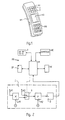
- Fig. 2 shows the block diagram of the handset MS with integrated radio pager.
- the messages received by the ready-to-receive mobile part MS for example messages transmitted via the paging system, are temporarily stored in the memory SP, decoded (microprocessor M) and displayed on the display device AE.
- the memory SP is, for example, a battery-backed RAM, a NOV-RAM (Nonvolatile Random Access Memory) or an EEPROM (Electrically Erasable Programmable Read Only Memory).
- the receiver device E consists of a first and second mixer M1, M2 and a demodulator D connected to the second mixer M2.
- a switching device S is arranged between the first and second mixer M1, M2.
- the two inputs of the switching device S are connected to two antennas A1, A2 and the output of the switching device S is connected to the input of the second mixer M2.
- the configuration of the receiver device E can be changed by the user (actuation of one of the operating elements B1) or automatically by the microprocessor M.
- the microprocessor M takes over the function of a transmitter search device and alternately scans all or some radio transmission channels of the cordless telephone set and the paging service for the presence of a connection request.
- a dialing aid W connected to the microprocessor M is arranged in the mobile part MS and stores the data and / or phone numbers coming from the calling subscriber or entered by the user in the memory SP.
- the phone numbers and / or data stored in the memory SP are called up and displayed on the display device AE connected to the dialing aid W and the microprocessor M.
- the dialing aid W controls the establishment of the connection to the calling subscriber on the basis of the number displayed.
- the dialing aid W automatically compares it Call numbers coming from the calling subscriber with the call numbers contained in the memory SP and only place the call numbers which have not yet been recognized as being available in free memory locations in the memory SP.
- the dialing aid W reads the data associated with this number from the memory SP in the case of matching numbers and displays them on the display device AE.
Abstract
Description
Die Erfindung betrifft eine Funkgerätekombination gemäß dem Oberbegriff des Patentanspruchs 1.The invention relates to a radio device combination according to the preamble of patent claim 1.
Um den Bewegungsbereich des Benutzer noch mehr zu erweitern, werden in verschiedenen Ländern zunehmend sogenannte schnurlose Telefonapparate (cordless telephone) eingesetzt. Die Informationsübertragung zwischen einer Basisstation und der zugehörigen Mobilstation des schnurlosen Telefonapparates erfolgt über ein Funkübertragungskanalpaar. Die Basisstation wird mittels einer Verbindungsdose an das Fernmeldenetz angeschlossen, so daß für den Benutzer beispielsweise der Zugang zum öffentlichen Fernsprechnetz möglich ist.So-called cordless telephones (cordless telephones) are increasingly being used in various countries to expand the user's range of motion. The information transmission between a base station and the associated mobile station of the cordless telephone set takes place via a pair of radio transmission channels. The base station is connected to the telecommunications network by means of a junction box, so that the user can, for example, access the public telephone network.
Dadurch, daß die Basisstation und die Mobilstation über einen Funkübertragungskanal miteinander in Verbindung stehen, ist der Bewegungsbereich des Benutzers auf einen Umkreis bis zu 200 m zum jeweiligen Anschluß (Verbindungsdose) erweitert.Because the base station and the mobile station are connected to one another via a radio transmission channel, the range of motion of the user is extended to a radius of up to 200 m to the respective connection (junction box).
In der Bundesrepubilk Deutschland stehen derzeit für die Informationsübertragung 80 Funkkanäle zur Verfügung, welche im Frequenzbereich von 900 MHz liegen. Mit der obengenannten Übertragungsreichweite ergibt sich für die Belegung des gleichen Funkkanals durch zueinander benachbarte schnurlose Telefonapparate eine geringe Belegwahrscheinlichkeit. Liegt ein Verbindungswunsch vor, so wird von einer im Empfänger von Mobilstation und Basisstation angeordneten Sendersuchlaufeinrichtung ein Suchlauf nach einem freien Funkübertragungskanal gestartet und das Funkübertragungskanalpaar belegt. Um sicherzustellen, daß die zwischen den beiden Stationen des schnurlosen Telefonapparates übertragenen Nachrichten von keinem anderen schnurlosen Telefonapparat mitgehört werden können, daß die Gebührenzuordnung sichergestellt ist und daß die Zuordnung der Funkübertragungskanalpaare eindeutig ist, ist jedem schnurlosen Telefonapparat eine Kennung zugeordnet, welche von der Fernsprechteilnehmernummer des Fernsprechteilnehmers unabhängig ist.In the Federal Republic of Germany 80 radio channels are currently available for information transmission, which are in the frequency range of 900 MHz. With the above-mentioned transmission range, there is little for the occupancy of the same radio channel by adjacent cordless telephones Document probability. If there is a connection request, a search run for a free radio transmission channel is started by a transmitter search device arranged in the receiver of the mobile station and base station and the pair of radio transmission channels is occupied. In order to ensure that the messages transmitted between the two stations of the cordless telephone set cannot be overheard by any other cordless telephone set, that the allocation of charges is ensured and that the assignment of the radio transmission channel pairs is unambiguous, each cordless telephone set is assigned an identifier which is derived from the subscriber's telephone number Telephone subscriber is independent.
Bei der Basisstation löst ein von der zugehörigen Steuereinrichtung erkannter ankommender Ruf auf der Amtsleitung die Funkkanalsuche aus. Durch Betätigen der Gabelumschalt-Taste wird in der Mobilstation die Funkkanalsuche eingeleitet. In der EP-B1-0 074 940 ist der dabei vorgenommene Kennungsaustausch näher beschrieben und erläutert. Ein als frei erkannter Funkübertragungskanal wird belegt, der Sender aktiviert und die Kennung als Datentelegramm über den Funkübertragungskanal gesendet. Nach dem Senden jeder Kennung wird auf ein Quittungstelegramm (Kennung) der entsprechenden Gegenstation gewartet. Wird die Kennung (Quittungstelegramm) der Gegenstation empfangen, so wird diese von einer in den jeweiligen Stationen angeordneten Einrichtung mit der eigenen Kennung verglichen. Bei Übereinstimmung wird von der mit der Einrichtung verbundenen Steuereinrichtung die
Verbindung durchgeschaltet, die Kennungsausgabe eingestellt und die bestehende Funkverbindung überwacht.At the base station, an incoming call recognized by the associated control device triggers the radio channel search on the outside line. The radio channel search is initiated in the mobile station by pressing the fork switch key. EP-B1-0 074 940 describes and explains the identification exchange carried out in this way. A radio transmission channel recognized as free is occupied, the transmitter is activated and the identifier is sent as a data telegram via the radio transmission channel. After each ID has been sent, an acknowledgment telegram (ID) from the corresponding remote station is waited for. If the identifier (acknowledgment telegram) from the remote station is received, then this is compared with its own identifier by a device arranged in the respective stations. If there is a match, the control device connected to the device
Connection switched through, the identification output set and the existing radio connection monitored.
Eine weitere Anwendung für schnurlose Telefonapparate ist bei öffentlichen Telepoint-Diensten gegeben. Beim Telepoint-Dienst sind die Basisstationen an öffentlichen Stellen, wie etwa an großen Plätzen, Bahnhöfen, Flughäfen, Einkaufszentren, Autobahnraststätten, usw. installiert. Der Besitzer eines geeigneten Handapparates (Mobilteil) kann im Umkreis von einigen 100 Metern einer solchen Basisstation an das öffentliche Fernsprechnetz gelangen, um Gespräche zu führen.Another application for cordless telephones is in public telepoint services. With the Telepoint service, the base stations are installed in public places such as large squares, train stations, airports, shopping centers, motorway service stations, etc. The owner of a suitable handset (handset) can reach the public telephone network within a few 100 meters of such a base station in order to conduct calls.
Eine solche Telepoint-Basisstation benötigt den Zugriff zu einer Datenbank, um die Berechtigung der Telepoint-Benutzer zu überprüfen, um die anfallenden Gesprächsgebühren zu verrechnen usw.. Dieser Zugriff erfolgt üblicherweise ebenfalls über das öffentliche Fernsprechnetz.Such a telepoint base station requires access to a database in order to check the authorization of the telepoint users, to charge the call charges incurred, etc. This access is usually likewise carried out via the public telephone network.
Anders als etwa bei einem Autotelefonsystem sollen beim Telepoint-Dienst ausschließlich das bestehende, meist analoge Fernsprechnetz und die Mobilteile der schnurlosen Telefonappparate weiter benutzt werden. Damit erhofft man sich Gesprächsgebühren, die nur unwesentlich über denjenigen eines normalen Telefons liegen. Aus diesem Grund erlauben die Telepoint-Konzepte lediglich abgehende Gespräche; anrufen kann man den Besitzer des Mobilteils beim Telepoint-Dienst nicht.In contrast to a car phone system, for example, only the existing, mostly analog telephone network and the handsets of the cordless telephone sets should be used in the telepoint service. One hopes for call charges that are only marginally higher than those of a normal telephone. For this reason, the telepoint concepts only allow outgoing calls; You cannot call the owner of the handset at the Telepoint service.
Um die Erreichbarkeit im häuslichen Bereich oder im Büro zu verbessern, wurde der europäische Funkrufdienst eingeführt, bei dem ein Funkrufempfänger über maximal vier Rufnummern erreichbar ist. In der Funkrufzentrale werden Codesignale gebildet, die dem mit der Funkrufzentrale verbundenen UKW-Sender zur Rufaussendung zugeführt werden. Die ausgesendeten Codesignale werden vom Funkrufempfänger empfangen und decodiert. Bei Übereinstimmung zwischen dem im Decoder eingestellten Code mit dem empfangenen Code werden ein akustisches und ein optisches Signal erzeugt. Die Bedeutung der Codesignale muß zwischen dem Funkrufteilnehmer und dem anrufenden Teilnehmer abgesprochen sein.In order to improve the accessibility in the home or in the office, the European paging service was introduced, in which a pager can be reached via a maximum of four numbers. In the paging center, code signals are formed which are fed to the FM transmitter connected to the paging center for transmitting calls. The transmitted code signals are received and decoded by the pager. If the code set in the decoder matches the code received, an acoustic and an optical signal are generated. The meaning of the code signals must be agreed between the pager and the calling party.
Weiterhin ist ein als City-Ruf bezeichneter Funkrufdienst bekannt. Beim City-Ruf werden kurze Informationen als Ziffern oder Texte auf der Anzeigeeinrichtung (Display) des Funkrufempfängers dargestellt. Die Informationsübermittlung ist beim City-Ruf in drei Rufklassen möglich: Nur-Ton für Ton-Funkrufempfänger, die entsprechend wie beim europäischen Funkrufdienst vier verabredete Signale empfangen können; Numeric für Numeric-Funkrufempfänger zum Empfang von bis zu fünfzehn Ziffern oder Sonderzeichen und Alphanumeric für Alphanumeric-Funkrufempfänger zum Empfangen von Text (Ziffern- und Buchstabenfolgen) bis zu achtzig Zeichen.A paging service known as a city call is also known. With a city call, brief information is displayed as digits or text on the display device of the pager. City calls can transmit information in three call classes: Tone-only for tone pagers, which can receive four agreed signals, as with the European paging service; Numeric for numeric pagers to receive up to fifteen digits or special characters and Alphanumeric for alphanumeric pagers to receive text (strings of digits and letters) up to eighty characters.
Der City-Rufdienst wird in regionalen Zonen (sog. Rufzonen) ausgestrahlt, wobei das Versorgungsgebiet in etwa den gesamten Einzugsbereich einer großen Stadt abdeckt.The city call service is broadcast in regional zones (so-called call zones), with the coverage area covering approximately the entire catchment area of a large city.
Das Funkrufnetz besteht aus den
Funkrufvermittlungsstellen, den Funkrufkonzentratoren, den Sendern und den Funkrufempfängern. Die Funkrufvermittlungsstelle verwaltet die Teilnehmerdaten und steuert die Sender, über welche ein Ruf ausgestrahlt werden soll. Der Zugang von den öffentlichen, drahtgebundenen Telekommunikationsnetzen (über die Vermittlungsstelle) zum Funkrufnetz ist unter gleicher Zugangskennzahl möglich und hängt nur von der Rufklasse und dem jeweiligen Eingabegerät für die City-Ruf-Informationen oder Mehrwertdienst-Nachrichten ab. Als Eingabegeräte dienen die in der Teilnehmerstelle installierten Endgeräte für die verschiedenen Postdienste, z.B. Fernsprechapparat, Telex-, Teletex- oder Btx-Endgerät. Da Numeric-Funkrufempfänger das Mehrfrequenz-Wählverfahren (MFV) erfordern, sind für eine Ziffern- und Texteingabe von einem einfachen Fernsprechapparat aus besondere Zusatzgeräte, z.B. akustisch ankoppelbare MFV-Geber, erforderlich. Soll von einem Personal- oder Home-Computer eine alphanumerische Information eingegeben werden, so ist dieser mit einem Akustikkoppler oder Modern zu verbinden.The paging network consists of the
Paging exchanges, the paging concentrators, the transmitters and the pagers. The paging exchange manages the subscriber data and controls the transmitters via which a call is to be broadcast. Access from the public, wireline telecommunications networks (via the switching center) to the paging network is possible with the same access code and only depends on the call class and the respective input device for the City Ruf information or value-added service messages. The terminal devices installed in the subscriber station for the various postal services, for example telephone, telex, teletex or BTX terminal, serve as input devices. Since numeric pagers require multi-frequency dialing (DTMF), special accessories such as acoustically connectable DTMF transmitters are required for entering numbers and text from a simple telephone. If alphanumeric information is to be entered from a personal or home computer, it must be connected to an acoustic coupler or modern.
Der City-Ruf kann von den Teilnehmern auch grenzüberschreitend genutzt werden, beispielsweise kann der Funkrufdienst Alphapage in Frankreich, Teledrine in Italien sowie Europage in Großbritannien genutzt werden. Hierzu muß sich der City-Ruf-Teilnehmer in eine internationale europäische Rufzone einbuchen. Für die Verwendung in Funkrufsystemen wurde ein europäischer Standard gemäß "CCIR Radio Paging Code No. 1" (Pocsag-Code gemäß British Post Office Code Standardistation Advisory Group) vereinbart. Die Struktur des Poscag-Codes
(beispielsweise in der EP-B1-0 118 153 beschrieben) und der Aufbau der Codewörter (Adreß- und Nachrichten-Codewörter) sind an die Eigenschaften des Funkübertragungskanals angepaßt.The city call can also be used by the participants across borders, for example the paging service Alphapage in France, Teledrine in Italy and Europage in Great Britain. To do this, the City Ruf subscriber must log into an international European call zone. A European standard in accordance with "CCIR Radio Paging Code No. 1" (Pocsag code in accordance with the British Post Office Code Standardization Advisory Group) has been agreed for use in paging systems. The structure of the Poscag code
(For example, described in EP-B1-0 118 153) and the structure of the code words (address and message code words) are adapted to the properties of the radio transmission channel.
Beim City-Ruf liegt das Frequenzband zwischen 450 und 470 MHz und zur funktechnischen Entkopplung benachbarter Rufzonen mit denselben Frequenzen (f1 = 465,97 MHz, f2 = 466,075 MHz und f3 = 466,23 MHz) werden die Nachrichten (Funkrufe) gemäß dem Zeitschlitzverfahren übertragen. Innerhalb einer Rufzone strahlen die Sender dieselbe Nachricht im Gleichwellenbetrieb ab. Die Dauer der Zeitschlitze ist zur Anpassung an die Verkehrsanforderungen einstellbar. Je nach gemessenem Verkehrswert werden die Funkrufe (Nachrichten) maximal dreimal gesendet. Bei Rufwiederholungen in einer Rufzone wird der Funkruf nur im selben Zeitschlitz wie bei der erstmaligen Aussendung des Funkrufs übertragen. Zum gleichen Funkrufempfänger können vor und zwischen den Rufwiederholungen neue Funkrufe gesendet werden.For city calls, the frequency band is between 450 and 470 MHz, and for radio decoupling of neighboring call zones with the same frequencies (f1 = 465.97 MHz, f2 = 466.075 MHz and f3 = 466.23 MHz), the messages (radio calls) are sent in accordance with the time slot procedure transfer. Within a call zone, the transmitters emit the same message in synchronous mode. The duration of the time slots can be adjusted to adapt to the traffic requirements. Depending on the measured market value, the radio calls (messages) are sent a maximum of three times. In the case of repeated calls in a call zone, the call is only transmitted in the same time slot as when the call was first sent. New radio calls can be sent to the same radio pager before and between the repetitions.
Jede Aussendung eines Funkrufs (Übertragungsabschnitt, Zeitschlitz) beginnt mit einer 576 Bit langen Präambel, die aus fortlaufenden Bitwechseln besteht. Die Präambel ermöglicht eine einfache Synchronisation im Decoder des Funkrufempfängers auf den Bittakt. An die Präambel schließen sich Datenblöcke (batches) an, die das Synchronwort und 16 weitere Codewörter enthalten. Die Struktur der Datenblöcke (Codewortgruppe) ist derart gewählt, daß immer zwei Codewörter zu einem Rahmen (frame) zusammengefaßt werden und daß jeder Datenblock acht solcher Rahmen enthält.Each transmission of a radio call (transmission section, time slot) begins with a 576-bit preamble, which consists of continuous bit changes. The preamble enables simple synchronization in the decoder of the pager to the bit clock. The preamble is followed by data blocks (batches) which contain the synchronous word and 16 further code words. The structure of the data blocks (code word group) is selected such that two code words are always combined to form a frame and that each data block contains eight such frames.
Zur Wortsynchronisation wird das Synchroncodewort im Funkrufempfänger ausgewertet. Alle Codewörter haben eine Länge von 32 Bit. Die Frequenzen f2 und f3 werden mit einer Übertragungsrate von 1.200 Baud anstelle von 512 Baud bei der Frequenz f1 genutzt.For word synchronization, the synchronous code word in the pager is evaluated. All code words are 32 bits long. The frequencies f2 and f3 are used with a transmission rate of 1,200 baud instead of 512 baud at the frequency f1.
Es können vier Typen von Codewörtern unterschieden werden, nämlich Synchron-, Adreß-, Nachrichten- und Füllcodewort. Adreß- und Nachrichtencodewort bestehen aus einem 21 Bit umfassenden Informationsfeld und 11 Prüfbits. Die ersten zehn Prüfbits werden nach den Regeln eines CRC-Verfahrens (cyclic redundancy check) gebildet und das elfte Bit ist ein Paritätsbit, das der Prüfung der geraden Parität des gesamten Codeworts dient. Adreß- und Nachrichtencodewort unterscheiden sich im ersten Bit. Im Adreßcodewort folgen nach dem ersten Bit weitere 18 Bits, welche dem Funkrufempfänger zugeordnet sind und zwei Funktionsbits, welche die Rufklasse (Nur-Ton, Numeric, Alphanumeric) kennzeichnen. Da die drei LSB-Bits des Adreß-Codeworts nicht übertragen werden, sondern die Rahmennummer definieren, in welchem das Adreß-Codewort übertragen wird, beträgt die Gesamtzahl der adressierbaren Funkrufempfänger über zwei Millionen.Four types of code words can be distinguished, namely synchronous, address, message and fill code words. The address and message code word consist of a 21-bit information field and 11 check bits. The first ten check bits are formed according to the rules of a CRC (cyclic redundancy check) method and the eleventh bit is a parity bit that is used to check the even parity of the entire code word. Address and message code word differ in the first bit. In the address code word, the first bit is followed by a further 18 bits which are assigned to the pager and two function bits which identify the call class (tone-only, numeric, alphanumeric). Since the three LSB bits of the address code word are not transmitted, but rather define the frame number in which the address code word is transmitted, the total number of addressable radio pagers is over two million.
Die Menge aller City-Rufempfänger ist in acht Gruppen aufgeteilt. Jeder Funkrufempfänger ist einer dieser acht Gruppen zugeordnet. Da der Funkrufempfänger nur Adreß-Codewörter in dem diesen zugeordneten Rahmen auswertet, kann zur Stromsparung der Funkrufempfänger während der übrigen sieben Rahmen eines Datenblocks ausgeschaltet werden. Auf diese Weise wird nicht nur der Stromverbrauch des Funkrufempfängers reduziert, sondern auch die Anzahl möglicher City-Ruf-Teilnehmer auf das Achtfache erhöht.The number of all city call receivers is divided into eight groups. Each pager is assigned to one of these eight groups. Since the pager only evaluates address code words in the frame assigned to them, the pager can save electricity during the remaining seven frames of a data block turned off. In this way, not only is the pager's power consumption reduced, but the number of possible city call subscribers is increased eightfold.
Bei einem Anruf setzt die Funkrufvermittlungsstelle (Rufzentrale) die gewählte Teilnehmernummer in ein entsprechendes Codewort um und wählt zur Nachrichtenübertragung die entsprechende Rufzone sowie die Frequenz aus. Die Nachrichten-Codewörter können in jedem Rahmen übertragen werden und folgen unmittelbar dem zugeordneten Adreß-Codewort. Eine Nachricht kann dabei eine beliebige Zahl von Nachrichten-Codewörter umfassen. Wenn es sich um eine längere Nachricht handelt, setzen sich die Nachrichten-Codewörter im nächsten Datenblock fort. Die Nachricht wird im Funkrufempfänger wieder formatiert, bevor diese angezeigt werden kann. In der Regel werden zwei aufeinander folgende Rufe mit Nachrichten durch mindestens einen Ruf der Rufklasse Nur-Ton oder durch ein Füllwort getrennt.When there is a call, the paging exchange (call center) converts the dialed subscriber number into a corresponding code word and selects the corresponding call zone and frequency for message transmission. The message code words can be transmitted in each frame and immediately follow the assigned address code word. A message can include any number of message code words. If it is a longer message, the message code words continue in the next data block. The message is reformatted in the pager before it can be viewed. As a rule, two consecutive calls with messages are separated by at least one call of the tone-only call class or by a noise word.
Schließlich ist aus der DE-PS 38 39 015 ein schnurloses Telefon bekannt, bei dem das Mobilteil des schnurlosen Telefons zusätzlich die Funktion eines Funkrufempfängers übernimmt. Hierzu wird die im Mobilteil vorhandene Schaltung aus Mikroprozessorschaltung, Bedienungs- und Anzeigeelementen mitbenutzt, um die vom Mobilteil empfangene Nachricht zu formatieren und anzuzeigen. Eine Anregung wie die Kombination aus Mobilteil und Funkrufempfänger realisiert werden kann, ist dem Gegenstand der DE-PS 38 39 015 nicht zu entnehmen.Finally, from DE-PS 38 39 015 a cordless telephone is known, in which the handset of the cordless telephone also takes on the function of a radio paging receiver. For this purpose, the circuit consisting of microprocessor circuit, operating and display elements in the handset is used in order to format and display the message received by the handset. A suggestion as to how the combination of handset and pager can be realized is not to be found in the subject of DE-PS 38 39 015.
Der Erfindung liegt die Aufgabe zugrunde, eine Funkgerätekombination, insbesondere aus Mobilteil und Funkrufempfänger der aus der DE-PS 38 39 015 genannten Art derart weiterzubilden, daß der für die Multidienstfähigkeit erforderliche Schaltungsaufwand gering ist.The invention has for its object to develop a radio device combination, in particular from a handset and pager of the type mentioned in DE-PS 38 39 015 such that the circuitry required for multi-service capability is low.
Diese Aufgabe wird bei einer gattungsgemäßen Funkgerätekombination durch die kennzeichnenden Merkmale des Patentanspruchs 1 gelöst.This object is achieved in a generic radio device combination by the characterizing features of claim 1.
Die erfindungsgemäße Funkgerätekombination weist den Vorteil auf, daß nur eine einzige Empfängereinrichtung für den Zugang zu verschiedenen Fernmeldediensten erforderlich ist. Durch die Mitbenutzung von Modulen der Empfängereinrichtung ist nicht nur der für die Multidienstfähigkeit erforderliche Schaltungsaufwand gering, sondern auf überraschend einfache Art und Weise wird eine bei einem Zweiempfängerkonzept möglicherweise auftretende gegenseitige Beeinflussung der beiden Empfänger zuverlässig vermieden. In jeder Phase des Übermittlungsvorgangs im Mobilteil ist eine hohe Übertragungssicherheit erreichbar, so daß die Voraussetzung für eine hohe Auswertesicherheit der empfangenen Nachrichten durch den Mikroprozessor gegeben ist.The radio device combination according to the invention has the advantage that only a single receiver device is required for access to different telecommunications services. By using modules of the receiver device, not only is the circuitry required for multi-service capability low, but in a surprisingly simple manner, a mutual influence of the two receivers that possibly occurs in a two-receiver concept is reliably avoided. A high level of transmission security can be achieved in every phase of the transmission process in the mobile part, so that the prerequisite for a high level of evaluation reliability of the received messages is given by the microprocessor.
Ist gemäß der Ausführungsform nach Patentanspruch 2 die Schalteinrichtung zwischen erstem und zweitem Mischer angeordnet, so kann in vorteilhafter Weise die erste Zwischenfrequenz gleich der Empfangsfrequenz des Rufempfängers gewählt werden.If, according to the embodiment according to
Die Ausführungsform der Funkgerätekombination gemäß Anspruch 3 weist den Vorteil auf, daß die beiden Antennen für die jeweilige Benutzung optimal gestaltet und dimensioniert werden können. Ist die Antenne im Gehäuse der Funkgerätekombination integriert, so kann durch eine Ringantenne der zur Verfügung stehende Raum ausgenutzt und auf einfache Art und Weise die abgreifbare Antennenspannung erhöht werden.The embodiment of the radio device combination according to claim 3 has the advantage that the two antennas can be optimally designed and dimensioned for the respective use. If the antenna is integrated in the housing of the radio device combination, the space available can be used by a ring antenna and the tapped antenna voltage can be increased in a simple manner.
Ist gemäß der Ausführungsform nach Patentanspruch 4 der erste Mischer als Verstärker schaltbar, so kann der Schaltungsaufwand weiter verringert werden, da im Vergleich zur Ausführungsform nach Patentanspruch 3 nur eine Antenne im Mobilteil erforderlich ist.If, according to the embodiment according to claim 4, the first mixer can be switched as an amplifier, the circuit complexity can be further reduced, since in comparison to the embodiment according to claim 3 only one antenna is required in the handset.
Die Ausführungsform nach Patentanspruch 5, bei der der Mikroprozessor die Funktion einer Sendersuchlaufeinrichtung übernimmt und abwechselnd die Funkübertragungskanäle auf das Vorliegen eines Verbindungswunsches abtastet, weist den Vorteil auf, daß ein stromsparender Betrieb der Funkgerätekombination ermöglicht wird.The embodiment according to claim 5, in which the microprocessor takes over the function of a transmitter search device and alternately scans the radio transmission channels for the presence of a connection request, has the advantage that energy-saving operation of the radio device combination is made possible.
Moderne Teilnehmereinrichtungen, insbesondere schnurlose Telefonapparate oder Funkgeräte, z.B. Autotelefon, weisen in der Regel eine Wählhilfe, insbesondere eine automatische Wähleinrichtung, auf. Wird gemäß der Ausführungsform nach Patentanspruch 5 der hierfür erforderliche Speicher mitbenutzt, um die über den Rufdienst kommenden Daten, insbesondere Rufnummern, zu speichern, so wird dem Benutzer auf überraschend einfache Art und Weise ein hoher Bedienkomfort geboten. Der Benutzer kann dabei in beim schnurlosen Telefonapparat gewohnter Weise unter Mitbenutzung der Wählhilfe die Verbindung zu einem anrufenden Teilnehmer herstellen.Modern subscriber devices, in particular cordless telephones or radio devices, for example car telephones, generally have a dialing aid, in particular an automatic dialing device. If, according to the embodiment according to claim 5, the memory required for this is also used in order to store the data coming in via the call service, in particular telephone numbers, the user is offered a surprisingly simple manner of great ease of use. The Users can establish the connection to a calling subscriber in the usual way with the cordless telephone set while using the dialing aid.
Die Ausführungsform der Funkgerätekombination nach Anspruch 7 weist den Vorteil auf, daß für die über das Funkrufsystem übermittelten Nachrichten, die erforderliche Speicherkapazität verringert werden kann. Es ist dabei lediglich die Speicherung einer Markierung für die betreffenden Rufnummern notwendig.The embodiment of the radio device combination according to claim 7 has the advantage that the required storage capacity can be reduced for the messages transmitted via the paging system. It is only necessary to save a mark for the relevant phone numbers.
Werden gemäß der Ausführungsform der
Funkgerätekombination nach Anspruch 8 auch die einer Rufnummer zugeordneten Daten an der Anzeigeeinrichtung dargestellt, so wird der Bedienkomfort für den Benutzer weiter erhöht. Durch die automatische Ergänzung der Rufnummer mit den im Speicher vorhandenen Daten kann der Benutzer sofort erkennen, um welchen Gesprächspartner es sich handeln wird.According to the embodiment of the
Radio device combination according to claim 8 also shows the data assigned to a phone number on the display device, so the ease of use for the user is further increased. By automatically supplementing the number with the data available in the memory, the user can immediately recognize which conversation partner it will be.
Die Erfindung wird im folgenden anhand einer in der Zeichnung dargestellten Ausführungsform näher beschrieben und erläutert.The invention is described and explained in more detail below with reference to an embodiment shown in the drawing.
Es zeigt:
- Fig. 1
- eine Ausführungsform der Benutzeroberfläche in Ansicht und
- Fig. 2
- das Blockschaltbild der in Fig. 1 dargestellten Ausführungsform.
- Fig. 1
- an embodiment of the user interface in view and
- Fig. 2
- the block diagram of the embodiment shown in Fig. 1.
Bei der in Fig. 1 dargestellten Ausführungsform der Benutzeroberfläche ist die Tastatur geteilt und beispielsweise die für die Steuerung des telepointfähigen Mobilteils oder Mobilteils eines schnurlosen Telefonapparats erforderlichen Bedienungselemente BE unterhalb angeordnet. Die Bedienungselemente B bzw. B1 zur Steuerung einer Anzeigeeinrichtung AE (für die Darstellung von über den Funkrufdienst empfangenen Daten) bzw. zur Änderung der Konfiguration einer Empfängereinrichtung E (siehe Fig. 2) und eine Taste T (zum Abruf im Speicher SP gespeicherter Rufnummern und/oder Daten; siehe Fig. 2) sind oberhalb der Anzeigeeinrichtung AE des Mobilteils MS angeordnet.In the embodiment of the user interface shown in FIG. 1, the keyboard is divided and for example, the control elements BE required for controlling the telepoint-capable handset or handset of a cordless telephone set are arranged below. The control elements B and B1 for controlling a display device AE (for displaying data received via the paging service) or for changing the configuration of a receiver device E (see FIG. 2) and a key T (for calling up phone numbers and stored in the memory SP / or data; see FIG. 2) are arranged above the display device AE of the handset MS.
Bei der nachfolgenden Erläuterung der erfindungsgemäßen Funkgerätekombination wird von der Anwendung bei einem schnurlosen Telefonapparat kombiniert mit einem Funkrufempfänger ausgegangen. Der Einsatz auch in anderen Nachrichtennetzen für vermittelte Verbindungen, beispielsweise bei einem Autotelefonsystem, ist ebenfalls möglich.In the following explanation of the radio device combination according to the invention, the application with a cordless telephone set combined with a radio paging receiver is assumed. It can also be used in other communication networks for switched connections, for example in a car phone system.
Fig. 2 zeigt das Blockschaltbild des Mobilteils MS mit integriertem Funkrufempfänger. Die vom empfangsbereiten Mobilteil MS empfangenen Nachrichten, beispielsweise über das Funkrufsystem übermittelte Nachrichten, werden im Speicher SP zwischengespeichert, decodiert (Mikroprozessor M) und an der Anzeigeeinrichtung AE angezeigt. Der Speicher SP ist beispielsweise ein batteriegestützes RAM, ein NOV-RAM (Nonvolatile Random Acces Memory) oder ein EEPROM (Electrically Erasable Programmable Read Only Memory).Fig. 2 shows the block diagram of the handset MS with integrated radio pager. The messages received by the ready-to-receive mobile part MS, for example messages transmitted via the paging system, are temporarily stored in the memory SP, decoded (microprocessor M) and displayed on the display device AE. The memory SP is, for example, a battery-backed RAM, a NOV-RAM (Nonvolatile Random Access Memory) or an EEPROM (Electrically Erasable Programmable Read Only Memory).
Die Empfängereinrichtung E besteht aus einem ersten und zweiten Mischer M1, M2 und einem mit dem zweiten Mischer M2 verbundenen Demodulator D. Bei der in Fig. 2 dargestellten Ausführungsform ist zwischen erstem und zweitem Mischer M1, M2 eine Schalteinrichtung S angeordnet. Die beiden Eingänge der Schalteinrichtung S sind mit zwei Antennen A1, A2 verbunden und der Ausgang der Schalteinrichtung S ist an dem Eingang des zweiten Mischers M2 angeschlossen.The receiver device E consists of a first and second mixer M1, M2 and a demodulator D connected to the second mixer M2. In the embodiment shown in FIG. 2, a switching device S is arranged between the first and second mixer M1, M2. The two inputs of the switching device S are connected to two antennas A1, A2 and the output of the switching device S is connected to the input of the second mixer M2.
Durch den Benutzer (Betätigung einer der Bedienelemente B1) oder automatisch durch den Mikroprozessor M ist die Konfiguration der Empfängereinrichtung E änderbar. In der automatischen Betriebsweise übernimmt der Mikroprozessor M die Funktion einer Sendersuchlaufeinrichtung und tastet abwechselnd alle oder einige Funkübertragungskanäle des schnurlosen Telefonapparats und des Funkrufdienstes auf das Vorliegen eines Verbindungswunsches ab.The configuration of the receiver device E can be changed by the user (actuation of one of the operating elements B1) or automatically by the microprocessor M. In the automatic mode of operation, the microprocessor M takes over the function of a transmitter search device and alternately scans all or some radio transmission channels of the cordless telephone set and the paging service for the presence of a connection request.
Schließlich ist im Mobilteil MS eine mit dem Mikroprozessor M verbundene Wählhilfe W angeordnet, welche die vom rufenden Teilnehmer kommenden oder vom Benutzer eingegebenen Daten und/oder Rufnummern im Speicher SP speichert. Durch Betätigen einer Taste T werden die im Speicher SP gespeicherten Rufnummern und/oder Daten abgerufen und an der mit der Wählhilfe W und dem Mikroprozessor M verbundenen Anzeigeeinrichtung AE dargestellt. Anhand der angezeigten Rufnummer steuert die Wählhilfe W den Verbindungsaufbau zum rufenden Teilnehmer. Zur besseren Ausnutzung des Speichers SP vergleicht die Wählhilfe W automatisch die vom rufenden Teilnehmer kommenden Rufnummern mit den im Speicher SP enthaltenen Rufnummern und legt nur die noch nicht als bereits vorhanden erkannten Rufnummern auf freie Speicherplätze des Speichers SP ab. Zur Erhöhung des Bedienungskomforts liest die Wählhilfe W - im Falle übereinstimmender Rufnummern - die dieser Rufnummer zugeordneten Daten aus dem Speicher SP aus und stellt diese an der Anzeigeeinrichtung AE dar.Finally, a dialing aid W connected to the microprocessor M is arranged in the mobile part MS and stores the data and / or phone numbers coming from the calling subscriber or entered by the user in the memory SP. By pressing a key T, the phone numbers and / or data stored in the memory SP are called up and displayed on the display device AE connected to the dialing aid W and the microprocessor M. The dialing aid W controls the establishment of the connection to the calling subscriber on the basis of the number displayed. To make better use of the memory SP, the dialing aid W automatically compares it Call numbers coming from the calling subscriber with the call numbers contained in the memory SP and only place the call numbers which have not yet been recognized as being available in free memory locations in the memory SP. To increase the ease of use, the dialing aid W reads the data associated with this number from the memory SP in the case of matching numbers and displays them on the display device AE.
Claims (8)
dadurch gekennzeichnet, daß die Empfängereinrichtung (E) aus einem ersten und zweiten Mischer (M1, M2) und einem mit dem zweiten Mischer (M2) verbundenen Demodulator (D) besteht und daß zwischen erstem und zweitem Mischer (M1, M2)) eine Schalteinrichtung (S) angeordnet ist.Radio equipment combination according to claim 1,
characterized in that the receiver device (E) consists of a first and second mixer (M1, M2) and a demodulator (D) connected to the second mixer (M2) and in that a switching device between the first and second mixer (M1, M2) (S) is arranged.
dadurch gekennzeichnet, daß das Mobilteil (MS) zwei Antennen (A1, A2) aufweist und daß die Schalteinrichtung (S), deren Ausgang an den zweiten Mischer (M2) angeschlossen ist, entweder mit dem ersten Mischer (M1) oder mit einer der beiden Antennen (A1, A2) verbunden ist.Radio device combination according to claim 1 or 2,
characterized in that the mobile part (MS) has two antennas (A1, A2) and that the switching device (S), the output of which is connected to the second mixer (M2), is either connected to the first mixer (M1) or to one of the two antennas (A1, A2).
dadurch gekennzeichnet, daß der erste Mischer (M1) als Verstärker schaltbar ist.Radio device combination according to claim 1 or 2,
characterized in that the first mixer (M1) can be switched as an amplifier.
dadurch gekennzeichnet, daß der Mikroprozessor (M) im Ruhezustand die Funktion einer Sendersuchlaufeinrichtung übernimmt und abwechselnd alle oder einige Funkübertragungskanäle des schnurlosen Telefonapparats und des Funkrufsystems auf das Vorliegen eines Verbindungswunsches abtastet.Radio equipment combination according to claim 1,
characterized in that the microprocessor (M) takes over the function of a station search device in the idle state and alternately scans all or some radio transmission channels of the cordless telephone set and the paging system for the presence of a connection request.
dadurch gekennzeichnet, daß im Mobilteil (MS) eine mit dem Mikroprozessor (M) verbundene Wählhilfe (W) angeordnet ist, welche die vom rufenden Teilnehmer kommenden oder vom Benutzer eingegebenen Daten oder Rufnummern in einem Speicher (SP) speichert, daß durch Betätigen einer Taste (T) die im Speicher (SP) gespeicherten Rufnummern und/oder Daten abgerufen und an einer mit der Wählhilfe (W) und dem Mikroprozessor (M) verbundenen Anzeigeeinrichtung (AE) dargestellt werden, und daß die Wählhilfe (W) den Verbindungsaufbau zum rufenden Teilnehmer steuert.Radio equipment combination according to claim 1,
characterized in that a dialing aid (W) connected to the microprocessor (M) is arranged in the handset (MS) and stores the data or call numbers coming from the calling subscriber or entered by the user in a memory (SP) by pressing a key (T) the numbers and / or data stored in the memory (SP) are retrieved and displayed on a display device (AE) connected to the dialing aid (W) and the microprocessor (M), and that the dialing aid (W) is used to establish the connection to the calling party Participant controls.
dadurch gekennzeichnet, daß die Wählhilfe (W) automatisch die vom rufenden Teilnehmer kommenden Rufnummern mit den im Speicher (SP) enthaltenen Rufnummern vergleicht und daß die Wählhilfe (W) nur die noch nicht als bereits vorhanden erkannten Rufnummern auf freie Speicherplätze des Speichers (SP) ablegt.Radio equipment combination according to claim 6,
characterized in that the dialing aid (W) automatically compares the call numbers coming from the calling subscriber with the call numbers contained in the memory (SP) and in that the dialing aid (W) only compares the call numbers which have not yet been recognized as being available to free memory locations of the memory (SP) discards.
dadurch gekennzeichnet, daß die Wählhilfe (W) im Falle übereinstimmender Rufnummern die dieser Rufnummer zugeordneten Daten aus dem Speicher (SP) ausliest und an der Anzeigeeinrichtung (AE) darstellt.Radio device combination according to claim 6 or 7,
characterized in that the dialing aid (W) reads the data assigned to this number from the memory (SP) in the case of matching numbers and displays them on the display device (AE).
Applications Claiming Priority (2)
| Application Number | Priority Date | Filing Date | Title |
|---|---|---|---|
| DE4019010A DE4019010A1 (en) | 1990-06-13 | 1990-06-13 | RADIO DEVICE COMBINATION, ESPECIALLY COMBINATION OF CORDLESS TELEPHONE DEVICE AND RADIO RECEIVER |
| DE4019010 | 1990-06-13 |
Publications (3)
| Publication Number | Publication Date |
|---|---|
| EP0461571A2 true EP0461571A2 (en) | 1991-12-18 |
| EP0461571A3 EP0461571A3 (en) | 1993-01-13 |
| EP0461571B1 EP0461571B1 (en) | 1997-01-02 |
Family
ID=6408380
Family Applications (1)
| Application Number | Title | Priority Date | Filing Date |
|---|---|---|---|
| EP91109436A Expired - Lifetime EP0461571B1 (en) | 1990-06-13 | 1991-06-08 | Combined radio apparatus, in particular combination of a cordless telephone and a paging receiver |
Country Status (4)
| Country | Link |
|---|---|
| EP (1) | EP0461571B1 (en) |
| AT (1) | ATE147215T1 (en) |
| DE (2) | DE4019010A1 (en) |
| DK (1) | DK0461571T3 (en) |
Cited By (3)
| Publication number | Priority date | Publication date | Assignee | Title |
|---|---|---|---|---|
| EP0458563A2 (en) * | 1990-05-21 | 1991-11-27 | Nokia Mobile Phones Ltd. | A multi-function telephone apparatus |
| EP0703719A1 (en) * | 1994-09-21 | 1996-03-27 | Philips Electronique Grand Public | On-board audio system |
| WO1997049192A1 (en) * | 1996-06-21 | 1997-12-24 | Fabio Agnetelli | Electronic apparatus for facilitating communications and meetings among two or more people, commercial transactions, job application/offer |
Families Citing this family (13)
| Publication number | Priority date | Publication date | Assignee | Title |
|---|---|---|---|---|
| DE4207205A1 (en) * | 1992-03-09 | 1993-09-16 | Votronic Entwicklung & Prod | Alternating transmitter for analog and/or digital signals - has base station and associated opposite station as transceiver units |
| DE9207008U1 (en) * | 1992-05-23 | 1993-09-23 | Emmerich Christoph Gmbh Co Kg | WIRELESS TELECOMMUNICATION TERMINAL |
| DE4307966C2 (en) * | 1993-03-12 | 2001-04-05 | Siemens Ag | Mobile radio system |
| DE4407059A1 (en) * | 1994-03-03 | 1995-09-14 | Axel Katerle | Mobile radio telephone usable as emergency telephone |
| EP0687117A3 (en) | 1994-06-06 | 1999-02-03 | Siemens Aktiengesellschaft | Radio-telephone system |
| DE19535612A1 (en) * | 1994-09-27 | 1996-03-28 | Dendorfer Claus | Mobile telephone with automatic call answering function |
| DE29504027U1 (en) * | 1995-03-09 | 1995-05-18 | Tamsit Vertriebsgesellschaft M | Electronic clock, in particular pocket or wristwatch |
| DE19527792B4 (en) * | 1995-07-19 | 2006-05-04 | Funkwerk Köpenick GmbH | Call forwarding to secondary call receiver |
| DE19743327A1 (en) * | 1997-09-30 | 1999-04-08 | Siemens Ag | Method of transmitting information to mobile part of cellular mobile radio system |
| DE19712230C2 (en) * | 1997-03-24 | 1999-07-29 | Harald Steinbrucker | Personal tracking device and tracking system |
| DE19806430A1 (en) * | 1998-02-17 | 1999-08-26 | Weinrich | Communications unit, e.g. for receiving RDS broadcast using car radio |
| DE19926069A1 (en) * | 1999-06-08 | 2000-12-21 | Susanne Porsche | Mobile phone |
| DE10331915A1 (en) * | 2003-07-15 | 2005-02-10 | Hirschmann Electronics Gmbh & Co. Kg | Hybrid receiver with adaptive intelligent algorithm |
Citations (5)
| Publication number | Priority date | Publication date | Assignee | Title |
|---|---|---|---|---|
| US4481382A (en) * | 1982-09-29 | 1984-11-06 | Villa Real Antony Euclid C | Programmable telephone system |
| US4644347A (en) * | 1983-08-10 | 1987-02-17 | Motorola, Inc. | Multiple frequency message system |
| US4747122A (en) * | 1986-10-27 | 1988-05-24 | Mobile Communications Corporation Of America | Mobile paging call back system and related method |
| US4849750A (en) * | 1987-10-20 | 1989-07-18 | Telefind Corp. | Paging receiver with dynamically programmable channel frequencies and functionality |
| EP0369123A2 (en) * | 1988-11-18 | 1990-05-23 | Robert Bosch Gmbh | Flexless telephone |
Family Cites Families (3)
| Publication number | Priority date | Publication date | Assignee | Title |
|---|---|---|---|---|
| AT391234B (en) * | 1981-09-08 | 1990-09-10 | Center Nachrichtentechnische A | WIRELESS TELEPHONE DEVICE |
| GB2136178A (en) * | 1983-02-25 | 1984-09-12 | Philips Electronic Associated | Pager decoding system |
| DE3433900A1 (en) * | 1984-09-14 | 1986-03-27 | Siemens AG, 1000 Berlin und 8000 München | Circuit arrangement for a data connection for mobile radio subscribers |
-
1990
- 1990-06-13 DE DE4019010A patent/DE4019010A1/en active Granted
-
1991
- 1991-06-08 AT AT91109436T patent/ATE147215T1/en not_active IP Right Cessation
- 1991-06-08 DE DE59108439T patent/DE59108439D1/en not_active Expired - Fee Related
- 1991-06-08 DK DK91109436.5T patent/DK0461571T3/en active
- 1991-06-08 EP EP91109436A patent/EP0461571B1/en not_active Expired - Lifetime
Patent Citations (5)
| Publication number | Priority date | Publication date | Assignee | Title |
|---|---|---|---|---|
| US4481382A (en) * | 1982-09-29 | 1984-11-06 | Villa Real Antony Euclid C | Programmable telephone system |
| US4644347A (en) * | 1983-08-10 | 1987-02-17 | Motorola, Inc. | Multiple frequency message system |
| US4747122A (en) * | 1986-10-27 | 1988-05-24 | Mobile Communications Corporation Of America | Mobile paging call back system and related method |
| US4849750A (en) * | 1987-10-20 | 1989-07-18 | Telefind Corp. | Paging receiver with dynamically programmable channel frequencies and functionality |
| EP0369123A2 (en) * | 1988-11-18 | 1990-05-23 | Robert Bosch Gmbh | Flexless telephone |
Cited By (4)
| Publication number | Priority date | Publication date | Assignee | Title |
|---|---|---|---|---|
| EP0458563A2 (en) * | 1990-05-21 | 1991-11-27 | Nokia Mobile Phones Ltd. | A multi-function telephone apparatus |
| EP0458563A3 (en) * | 1990-05-21 | 1992-10-21 | Nokia Mobile Phones Ltd. | A multi-function telephone apparatus |
| EP0703719A1 (en) * | 1994-09-21 | 1996-03-27 | Philips Electronique Grand Public | On-board audio system |
| WO1997049192A1 (en) * | 1996-06-21 | 1997-12-24 | Fabio Agnetelli | Electronic apparatus for facilitating communications and meetings among two or more people, commercial transactions, job application/offer |
Also Published As
| Publication number | Publication date |
|---|---|
| EP0461571A3 (en) | 1993-01-13 |
| DE4019010C2 (en) | 1992-10-22 |
| DK0461571T3 (en) | 1997-06-16 |
| DE4019010A1 (en) | 1992-01-02 |
| EP0461571B1 (en) | 1997-01-02 |
| DE59108439D1 (en) | 1997-02-13 |
| ATE147215T1 (en) | 1997-01-15 |
Similar Documents
| Publication | Publication Date | Title |
|---|---|---|
| EP0461571B1 (en) | Combined radio apparatus, in particular combination of a cordless telephone and a paging receiver | |
| DE19580642C2 (en) | Method for authorizing a base station and for authenticating a base station and an authorization device | |
| DE69824729T2 (en) | Lowest cost designated router | |
| EP0201126B1 (en) | Integrated services radio transmission system | |
| EP0461572B1 (en) | Multifunctional radio apparatus switching between different operation modes | |
| DE2462438A1 (en) | PROCEDURE FOR MAINTAINING A TELEPHONE CONNECTION BETWEEN FIXED AND MOBILE UNIT | |
| DE2727808A1 (en) | AUTOMATIC RADIO TELEPHONE SYSTEM | |
| DE4236778A1 (en) | Method for connecting transmitters / receivers of a cordless communication system to form a communication-capable unit | |
| EP0925697B1 (en) | Process for initiating emergency calls in cordless telecommunication systems, in particular dect/gap systems | |
| DE4240249C1 (en) | Switching device and method for a radio telephony system with the character of a local or branch exchange | |
| EP0544100B1 (en) | Method for enabling controlled listening-in to cordless telephone | |
| DE69820208T2 (en) | TDMA communication system and method | |
| DE2536452A1 (en) | Car radio telephone subscriber search system - enables calling subscriber to dial search code to examine memory of local exchange information units | |
| EP0444479B1 (en) | Method for a value-added service for a communication system with wired and/or wireless channels | |
| EP1018278B1 (en) | Dual mode mobile telephone | |
| DE2251602C2 (en) | Method for transmitting a digital data signal | |
| DE19745350C1 (en) | Mobile radio telephone for multi-mode operation and use of a relay station for such mobile radio telephones | |
| EP0422429B1 (en) | Cordless telephone with a channel scanning device located both in the mobile and the base stations and with a memory connected to the channel scanning device | |
| DE69634331T2 (en) | METHOD AND DEVICE FOR NOTIFYING THE MODE OF OPERATION OF A CORDLESS COMMUNICATION DEVICE TO A CORDLESS NETWORK | |
| DE69831038T2 (en) | Communication method in a cordless telephone system | |
| EP0729284A2 (en) | Mobile radio system with a base station comprising a monitoring device | |
| DE69733569T2 (en) | CONSTRUCTION OF A TELECOMMUNICATIONS CONNECTION | |
| EP0164312B1 (en) | Method for the remote programming of at least one station code in a radio station, and radio station for the application of the method | |
| EP1084558B1 (en) | Supplementary device for mobile radio devices for connecting with telecommunications networks | |
| DE4236777A1 (en) | Method for managing a plurality of mobile stations of a cordless communication system registered in a base station |
Legal Events
| Date | Code | Title | Description |
|---|---|---|---|
| PUAI | Public reference made under article 153(3) epc to a published international application that has entered the european phase |
Free format text: ORIGINAL CODE: 0009012 |
|
| AK | Designated contracting states |
Kind code of ref document: A2 Designated state(s): AT CH DE DK FR GB IT LI SE |
|
| PUAL | Search report despatched |
Free format text: ORIGINAL CODE: 0009013 |
|
| 17P | Request for examination filed |
Effective date: 19921024 |
|
| AK | Designated contracting states |
Kind code of ref document: A3 Designated state(s): AT CH DE DK FR GB IT LI SE |
|
| 17Q | First examination report despatched |
Effective date: 19950214 |
|
| RAP1 | Party data changed (applicant data changed or rights of an application transferred) |
Owner name: GRUNDIG E.M.V. ELEKTRO-MECHANISCHE VERSUCHSANSTALT |
|
| GRAG | Despatch of communication of intention to grant |
Free format text: ORIGINAL CODE: EPIDOS AGRA |
|
| GRAH | Despatch of communication of intention to grant a patent |
Free format text: ORIGINAL CODE: EPIDOS IGRA |
|
| GRAH | Despatch of communication of intention to grant a patent |
Free format text: ORIGINAL CODE: EPIDOS IGRA |
|
| GRAA | (expected) grant |
Free format text: ORIGINAL CODE: 0009210 |
|
| AK | Designated contracting states |
Kind code of ref document: B1 Designated state(s): AT CH DE DK FR GB IT LI SE |
|
| REF | Corresponds to: |
Ref document number: 147215 Country of ref document: AT Date of ref document: 19970115 Kind code of ref document: T |
|
| REG | Reference to a national code |
Ref country code: CH Ref legal event code: NV Representative=s name: BOVARD AG PATENTANWAELTE Ref country code: CH Ref legal event code: EP |
|
| GBT | Gb: translation of ep patent filed (gb section 77(6)(a)/1977) |
Effective date: 19970102 |
|
| REF | Corresponds to: |
Ref document number: 59108439 Country of ref document: DE Date of ref document: 19970213 |
|
| ET | Fr: translation filed | ||
| ITF | It: translation for a ep patent filed |
Owner name: 0403;07MIFSTUDIO JAUMANN |
|
| PG25 | Lapsed in a contracting state [announced via postgrant information from national office to epo] |
Ref country code: AT Free format text: LAPSE BECAUSE OF NON-PAYMENT OF DUE FEES Effective date: 19970608 |
|
| REG | Reference to a national code |
Ref country code: DK Ref legal event code: T3 |
|
| PLBE | No opposition filed within time limit |
Free format text: ORIGINAL CODE: 0009261 |
|
| STAA | Information on the status of an ep patent application or granted ep patent |
Free format text: STATUS: NO OPPOSITION FILED WITHIN TIME LIMIT |
|
| 26N | No opposition filed | ||
| REG | Reference to a national code |
Ref country code: FR Ref legal event code: TP |
|
| REG | Reference to a national code |
Ref country code: FR Ref legal event code: D6 |
|
| REG | Reference to a national code |
Ref country code: GB Ref legal event code: IF02 |
|
| REG | Reference to a national code |
Ref country code: CH Ref legal event code: PUE Owner name: GRUNDIG MULTIMEDIA B.V. Free format text: GRUNDIG E.M.V. ELEKTRO-MECHANISCHE VERSUCHSANSTALT MAX GRUNDIG GMBH & CO. KG#KURGARTENSTRASSE 37#D-90762 FUERTH (DE) -TRANSFER TO- GRUNDIG MULTIMEDIA B.V.#DE BOELELAAN 7 OFF. I 2 HG#1083HJ AMSTERDAM (NL) |
|
| REG | Reference to a national code |
Ref country code: GB Ref legal event code: 732E |
|
| REG | Reference to a national code |
Ref country code: FR Ref legal event code: TP |
|
| PGFP | Annual fee paid to national office [announced via postgrant information from national office to epo] |
Ref country code: DK Payment date: 20090620 Year of fee payment: 19 |
|
| PGFP | Annual fee paid to national office [announced via postgrant information from national office to epo] |
Ref country code: IT Payment date: 20090619 Year of fee payment: 19 |
|
| PGFP | Annual fee paid to national office [announced via postgrant information from national office to epo] |
Ref country code: CH Payment date: 20090623 Year of fee payment: 19 |
|
| PGFP | Annual fee paid to national office [announced via postgrant information from national office to epo] |
Ref country code: DE Payment date: 20090625 Year of fee payment: 19 Ref country code: SE Payment date: 20090713 Year of fee payment: 19 Ref country code: GB Payment date: 20090624 Year of fee payment: 19 |
|
| REG | Reference to a national code |
Ref country code: DK Ref legal event code: EBP Ref country code: CH Ref legal event code: PL |
|
| EUG | Se: european patent has lapsed | ||
| GBPC | Gb: european patent ceased through non-payment of renewal fee |
Effective date: 20100608 |
|
| REG | Reference to a national code |
Ref country code: FR Ref legal event code: ST Effective date: 20110228 |
|
| PG25 | Lapsed in a contracting state [announced via postgrant information from national office to epo] |
Ref country code: IT Free format text: LAPSE BECAUSE OF NON-PAYMENT OF DUE FEES Effective date: 20100608 |
|
| PG25 | Lapsed in a contracting state [announced via postgrant information from national office to epo] |
Ref country code: LI Free format text: LAPSE BECAUSE OF NON-PAYMENT OF DUE FEES Effective date: 20100630 Ref country code: CH Free format text: LAPSE BECAUSE OF NON-PAYMENT OF DUE FEES Effective date: 20100630 Ref country code: DE Free format text: LAPSE BECAUSE OF NON-PAYMENT OF DUE FEES Effective date: 20110101 |
|
| PG25 | Lapsed in a contracting state [announced via postgrant information from national office to epo] |
Ref country code: FR Free format text: LAPSE BECAUSE OF NON-PAYMENT OF DUE FEES Effective date: 20100630 |
|
| PG25 | Lapsed in a contracting state [announced via postgrant information from national office to epo] |
Ref country code: GB Free format text: LAPSE BECAUSE OF NON-PAYMENT OF DUE FEES Effective date: 20100608 |
|
| PG25 | Lapsed in a contracting state [announced via postgrant information from national office to epo] |
Ref country code: DK Free format text: LAPSE BECAUSE OF NON-PAYMENT OF DUE FEES Effective date: 20100630 |
|
| PG25 | Lapsed in a contracting state [announced via postgrant information from national office to epo] |
Ref country code: SE Free format text: LAPSE BECAUSE OF NON-PAYMENT OF DUE FEES Effective date: 20100609 |
|
| PGFP | Annual fee paid to national office [announced via postgrant information from national office to epo] |
Ref country code: FR Payment date: 20090619 Year of fee payment: 19 |