EP0465833A1 - Plastic can carrier and method of making - Google Patents
Plastic can carrier and method of making Download PDFInfo
- Publication number
- EP0465833A1 EP0465833A1 EP91109295A EP91109295A EP0465833A1 EP 0465833 A1 EP0465833 A1 EP 0465833A1 EP 91109295 A EP91109295 A EP 91109295A EP 91109295 A EP91109295 A EP 91109295A EP 0465833 A1 EP0465833 A1 EP 0465833A1
- Authority
- EP
- European Patent Office
- Prior art keywords
- layer
- film
- sheet
- web
- carrier
- Prior art date
- Legal status (The legal status is an assumption and is not a legal conclusion. Google has not performed a legal analysis and makes no representation as to the accuracy of the status listed.)
- Withdrawn
Links
Images

Classifications
-
- B—PERFORMING OPERATIONS; TRANSPORTING
- B65—CONVEYING; PACKING; STORING; HANDLING THIN OR FILAMENTARY MATERIAL
- B65D—CONTAINERS FOR STORAGE OR TRANSPORT OF ARTICLES OR MATERIALS, e.g. BAGS, BARRELS, BOTTLES, BOXES, CANS, CARTONS, CRATES, DRUMS, JARS, TANKS, HOPPERS, FORWARDING CONTAINERS; ACCESSORIES, CLOSURES, OR FITTINGS THEREFOR; PACKAGING ELEMENTS; PACKAGES
- B65D71/00—Bundles of articles held together by packaging elements for convenience of storage or transport, e.g. portable segregating carrier for plural receptacles such as beer cans or pop bottles; Bales of material
- B65D71/50—Bundles of articles held together by packaging elements for convenience of storage or transport, e.g. portable segregating carrier for plural receptacles such as beer cans or pop bottles; Bales of material comprising a plurality of articles held together only partially by packaging elements formed otherwise than by folding a blank
-
- B—PERFORMING OPERATIONS; TRANSPORTING
- B65—CONVEYING; PACKING; STORING; HANDLING THIN OR FILAMENTARY MATERIAL
- B65B—MACHINES, APPARATUS OR DEVICES FOR, OR METHODS OF, PACKAGING ARTICLES OR MATERIALS; UNPACKING
- B65B17/00—Other machines, apparatus, or methods for packaging articles or materials
- B65B17/02—Joining articles, e.g. cans, directly to each other for convenience of storage, transport, or handling
- B65B17/025—Joining articles, e.g. cans, directly to each other for convenience of storage, transport, or handling the articles being joined by a top carrier element
-
- Y—GENERAL TAGGING OF NEW TECHNOLOGICAL DEVELOPMENTS; GENERAL TAGGING OF CROSS-SECTIONAL TECHNOLOGIES SPANNING OVER SEVERAL SECTIONS OF THE IPC; TECHNICAL SUBJECTS COVERED BY FORMER USPC CROSS-REFERENCE ART COLLECTIONS [XRACs] AND DIGESTS
- Y10—TECHNICAL SUBJECTS COVERED BY FORMER USPC
- Y10T—TECHNICAL SUBJECTS COVERED BY FORMER US CLASSIFICATION
- Y10T428/00—Stock material or miscellaneous articles
- Y10T428/24—Structurally defined web or sheet [e.g., overall dimension, etc.]
- Y10T428/24273—Structurally defined web or sheet [e.g., overall dimension, etc.] including aperture
- Y10T428/24322—Composite web or sheet
- Y10T428/24331—Composite web or sheet including nonapertured component
Definitions
- This invention relates to container packages and particularly to carriers for container packages and the method of making such carriers.
- a carrier having an array of openings therein for receiving the upper ends of the cans and holding an array of cans to form a container package.
- Typical United States patents showing such a carrier are U.S. 3,874,502 and 4,219,117.
- Such a carrier comprises a series of bands or rings which are non-circular and is applied by lateral stretching by a machine which inserts fingers into the openings to stretch the openings to a generally circular configuration and then the carrier is forced onto the upper end of the cans through the neck below the chime or bead on the cans.
- the bands are folded downwardly along the peripheral surface of the necks of the cans.
- the resultant package comprised a plurality of array of the cans surrounded by the stretched plastic rings. In such a package, the upper ends of the cans are exposed.
- the package offers no area wherein the carrier can be provided with printing, advertising or other indicia.
- the cans can not be readily handled for returning the cans for salvage or reclaiming.
- a container package comprises an array of cans and a carrier.
- the carrier includes a sheet of stiff but flexible plastic material having a plurality of openings forming an array for receiving the ends of the cans and a film of plastic material coextensive with the sheet and bonded to the periphery of the sheet so that it is flat and taut on the sheet.
- the cans are inserted upwardly into the openings and retained by the carrier by flexing of the periphery of each opening upwardly against the chime or bead of each can. As the cans are inserted, the film is stretched taut over the upper ends of the cans.
- the film is stretched substantially flat and taut from one peripheral edge to an opposite peripheral edge.
- the carrier thus protects the cans from contaminants.
- the carrier supports the array of the cans so that the upper ends of the cans are in a single plane when the package is lifted through finger openings in the film and sheet.
- the film and sheet define a substantially flat planar upper surface. Indicia such as printing, advertising, logos artwork and other markings are provided on the film preferably on the entire surface of the film.
- the aforementioned patent describes a method of making carriers by first passing a plastic sheet through a rotary cutting die forming a strip with openings and then feeding the strip and a web of film from a roll between a heated roller that has longitudinal heated ribs that bond the film to a strip of carriers along the periphery.
- Transverse ribs comprise spaced ribs thereby defining separate carriers that can be severed.
- the transverse ribs comprise ribs of double widths so that when the carriers are subsequently cut from the web, a desired peripheral edge is provided.
- Roll includes arcuate bonding portions for bonding the portions from which tabs are to be formed.
- the web of carriers is then passed through a die cutting roll which includes cutting edges that trim the side edges, cutting portions that trim the corners, and cutting edges that simultaneously form the fingers tabs.
- the objectives of the present invention are to provide a carrier which can be made rapidly at high speeds without melting and burning through the film; which produces a proper bond of the film to the sheet strip; and which is produced by method that obviates the aforementioned problems.
- a carrier for a container package holding an array of cans each of which has an annular bead on the upper end thereof comprises a sheet of flexible plastic material having a plurality of openings forming an array for receiving the ends of the cans and at least one film of plastic material coextensive with the sheet and bonded to the periphery of the sheet.
- the sheet is made as a coextruded sheet comprising a first layer relatively thick and a second relatively thin layer adjacent the film.
- the second layer has a melting point lower than that of the first layer or the film and facilitates the bonding of the film to the sheet by heat.
- two layers of film are bonded to the sheet.
- the container package embodying the invention comprises a carrier 20 including a plurality or array of containers C, such as 12 cans, supported so the side wall W of the containers C are in adjacent abutting relation.
- the cans include an annular chime or bead B that is connected to the side wall W by a tapered neck portion N.
- the carrier 20 comprises a sheet 21 which is preferably made of relatively stiff flexible plastic of uniform thickness which is generally rectangular and has a plurality of openings 22 corresponding in number to the number of cans for the package, preferably twelve.
- the openings 22 have a cross sectional area slightly less then the diameter of the cans below the bead B. As shown, the openings 22 are circular.
- the carrier 20 further includes a relatively thin film 23 which is thinner then the sheet 21 and is coextensive with the sheet 21 and bonded about the periphery 24.
- the bonding at the periphery of the lines is preferably by heat.
- the carrier 20 further includes portions partially cut to form arcuate slots 25 in the film 23 and sheet 21 to define tabs 26 (Fig. 2), each of which comprises a layer of plastic from the carrier sheet 21 and a layer of plastic from the film 23.
- Tabs 26 are adapted to be bent downwardly to provide openings to receive the fingers of a hand in order to lift and carry the package, the openings being preferably spaced transversely of one another.
- Arcuate bonding lines 27 are provided about the periphery of the tabs the tabs 26 minimizing the likelihood of detachment of the film from the sheet at the tabs.
- the portions 22a of the periphery of the openings 22 are flexed upwardly about the beads B of the cans C and then flexed radially inwardly below the beads B.
- the periphery of the portion of the carriers surrounding the opening flexes only sufficiently to extend upwardly beneath the bead but preferably not such that it is stretched and engages and conforms to the neck N of the can C as occurs in conventional ring type can carriers.
- Such ring type carriers that are commercially used at the present time are shown in the aforementioned patents 3,874,502, 4,219,177 and 4,586,742.
- the film 23 is flexed about the upper ends of the cans so that the portion 23a of the film at the periphery is inclined upwardly and inwardly toward the tops of the peripheral cans and the remainder of the film between the peripheral edges in the longitudinal direction is taut and extends generally parallel to the sheet 21 or horizontally when the package is on a horizontal surface.
- the entire portion 23b overlying the cans is taut and extends horizontally.
- the film portions 23a at the periphery are also inclined upwardly and inwardly toward the tops of the cans and the portion 23b.
- the entire portion 23b of the film over the tops of the cans is taut and extends horizontally.
- the indicia 30, 31 and other markings 33 or background may be applied by printing on the outer surface of the film 23.
- the indicia may comprise an opaque color to the film or sheet.
- the film 23 is substantially uniformly stretched from one peripheral edge to the opposite peripheral edge.
- the indicia can be applied over the entire surface of the carrier without unsightly distortion of the indicia by the stretching of the film 23 during application.
- film 35 is transparent and the indicia 36 are provided on the underside of the film 35.
- this form is constructed like that shown in Figs. 1-6. This form has the advantage of protecting the indicia from scuffing when packages are handled or stacked on one another for shipping or display.
- the film comprised an outer transparent film layer 40 having indicia 43 on the underside of layer 40 and an inner film layer 41.
- the indicia 43 are formed on the inner surface of layer 40 or 41.
- An adhesive 42 may be provided to bond the two layers to one another to form a single film.
- the indicia are provided on the underside of the film, they are less subjected to abrasive action of the cans on another package during the application to the cans, normal handling, storage and stacking of one package on another.
- the indicia are provided between two layers of film, abrasive action of the printing ink with the upper ends of the cans in the package, which might mar the indicia, is obviated.
- the carrier 20c is similar to that shown in Fig. 8 except that the transparent layer 40a having indicia on the underside and film layer 41 a are not bonded by an adhesive to one another.
- the outer film layer 40a and the inner film layer 41 a can slide or move relative to one another minimizing any tendency to deform or mar the indicia 43a during application of the carrier to the cans.
- the sheet 21 comprises two coextruded layers, a relatively stiff flexible plastic layer 21 a of uniform thickness and a second layer 21 b coextruded with the first layer and being substantially thinner than the first layer and bonded to the film or films.
- the coextruded second layer 21 b has a melting point less than that of the first layer 21 a and less than that of the film or films which are bonded to the sheet 21.
- the first thick layer 21 a of plastic is substantially thicker than the second layer 21 b and the film or films bonded to the sheet are thicker than the second coextruded layer.
- the sheet comprises high density polyethylene as the first layer 21 a and ultra low density polyethylene as the coextruded layer 21 b and the film or films comprise an outer film or films having a total thickness of 2.5 mils.
- the outer layer having a thickness of 1.5 mils
- the inner layer having a thickness of 1 mil
- the coextruded layer 21 b having a thickness of at least 0.5 mil but preferably 0.75 mil while the sheet has a thickness of 13.5 mils. Satisfactory result from the standpoint of bonding of the films to the coextruded sheet are achieved with such a sheet.
- the first layer 21 a of the coextruded sheet has a thickness of 13.50 mil and comprises high density polyethylene having a melting point of 135°C, density of 0.960 and a melt index of 0.3, made by Allied Signal Inc., and sold under the designation Paxon AA60-003;
- the coextruded layer having a thickness of 0.75 mil comprises ultra low density polyethylene having a melting point of 105-110 F and a softening point of about 90 F, density of 0.905 and a melt index of 0.8, made by Dow Chemical Company and sold under the designation Attane 4003; an intermediate film having a thickness of 1 mil and comprising an ultra low density polyethylene having a melting point of 120° F, a density of 0.912 and a melt index of 3.3 and sold by Dow Chemical Company under the designation Attane 4004; and the top film layer comprises a linear low density polyethylene layer having a melting point of 128° F and a thickness of 1.5 mil, a density of 0.
- EVA ethylene glycol dimethacrylate copolymer
- EEA ethylene glycol dimethacrylate copolymer
- other low melting copolymers may be used as the coextruded layer.
- the carriers are preferably formed by first forming a strip S with openings 22 and feeding the strip S and a web of film F from a roll between a heated roller 45 that has longitudinal heated ribs 46 that bond the film to a strip of carriers along the periphery 24.
- Transverse ribs 47 comprise spaced ribs thereby defining separate carriers that can be severed.
- the transverse ribs 47 comprise ribs of double widths so that when the carriers are subsequently cut from the web, a desired peripheral edge 24 is provided.
- Roll 45 included arcuate bonding portions 48 for bonding the portions from which tabs 26 are to be formed.
- the web of carriers are then passed through a die cutting roll 49 which includes cutting edges 49a that trim the side edges, cutting portions 49b that trim the corners, and cutting edges 49c that simultaneously form the finer tabs 26.
- a carrier which can be made rapidly at high speeds without melting and burning through the film; which produces a proper bond of the film to the sheet strip; and which is produced by method that obviates the aforementioned problems.
Abstract
A carrier (20) for a container package holding an array of cans (C) each of which has an annular bead (B) on the upper end thereof comprising a sheet (21) of flexible plastic material having a plurality of openings (22) forming an array for receiving the ends of the cans and at least one film (23) of plastic material coextensive with the sheet and bonded to the periphery of the sheet. The sheet is made as a coextruded sheet comprising a first relatively thicker layer (21a) and a second relatively thin layer adjacent the film (21 b). The second layer has a melting point lower than that of the first layer or the film and facilitates the bonding of the film to the sheet by heat. In a modified form two layers of film are bonded to the sheet.
Description
- This invention relates to container packages and particularly to carriers for container packages and the method of making such carriers.
- In the handling and the packaging of cans, it is common to use a carrier having an array of openings therein for receiving the upper ends of the cans and holding an array of cans to form a container package. Typical United States patents showing such a carrier are U.S. 3,874,502 and 4,219,117.
- Such a carrier comprises a series of bands or rings which are non-circular and is applied by lateral stretching by a machine which inserts fingers into the openings to stretch the openings to a generally circular configuration and then the carrier is forced onto the upper end of the cans through the neck below the chime or bead on the cans. During the stretching and application, the bands are folded downwardly along the peripheral surface of the necks of the cans. The resultant package comprised a plurality of array of the cans surrounded by the stretched plastic rings. In such a package, the upper ends of the cans are exposed. The package offers no area wherein the carrier can be provided with printing, advertising or other indicia. Furthermore, once the cans are removed from the carrier, it is difficult if not impossible to reinsert the cans. Accordingly, the cans can not be readily handled for returning the cans for salvage or reclaiming.
- In United States Patent 4,911,290, having a common assignee with the present application, there is disclosed and claimed a container package comprises an array of cans and a carrier. The carrier includes a sheet of stiff but flexible plastic material having a plurality of openings forming an array for receiving the ends of the cans and a film of plastic material coextensive with the sheet and bonded to the periphery of the sheet so that it is flat and taut on the sheet. The cans are inserted upwardly into the openings and retained by the carrier by flexing of the periphery of each opening upwardly against the chime or bead of each can. As the cans are inserted, the film is stretched taut over the upper ends of the cans. The film is stretched substantially flat and taut from one peripheral edge to an opposite peripheral edge. The carrier thus protects the cans from contaminants. The carrier supports the array of the cans so that the upper ends of the cans are in a single plane when the package is lifted through finger openings in the film and sheet. The film and sheet define a substantially flat planar upper surface. Indicia such as printing, advertising, logos artwork and other markings are provided on the film preferably on the entire surface of the film.
- The aforementioned patent describes a method of making carriers by first passing a plastic sheet through a rotary cutting die forming a strip with openings and then feeding the strip and a web of film from a roll between a heated roller that has longitudinal heated ribs that bond the film to a strip of carriers along the periphery. Transverse ribs comprise spaced ribs thereby defining separate carriers that can be severed. The transverse ribs comprise ribs of double widths so that when the carriers are subsequently cut from the web, a desired peripheral edge is provided. Roll includes arcuate bonding portions for bonding the portions from which tabs are to be formed.
- The web of carriers is then passed through a die cutting roll which includes cutting edges that trim the side edges, cutting portions that trim the corners, and cutting edges that simultaneously form the fingers tabs.
- By this method, a roll of carriers is provided that can then be applied to successive arrays of cans.
- In utilizing such a method of making a strip of interconnected carriers, it has been found that the rate of production is limited. If the heated roller is rotated rapidly, insufficient bonding is provided between the film and the strip of sheet material. If the heated roller is rotated at a low speed, sufficient to provide proper bonding, the heat tends to melt and burn through the film so that a proper bonding is not achieved.
- Accordingly, among the objectives of the present invention are to provide a carrier which can be made rapidly at high speeds without melting and burning through the film; which produces a proper bond of the film to the sheet strip; and which is produced by method that obviates the aforementioned problems.
- In accordance with the invention, a carrier for a container package holding an array of cans each of which has an annular bead on the upper end thereof comprises a sheet of flexible plastic material having a plurality of openings forming an array for receiving the ends of the cans and at least one film of plastic material coextensive with the sheet and bonded to the periphery of the sheet. The sheet is made as a coextruded sheet comprising a first layer relatively thick and a second relatively thin layer adjacent the film. The second layer has a melting point lower than that of the first layer or the film and facilitates the bonding of the film to the sheet by heat. In a modified form two layers of film are bonded to the sheet.
-
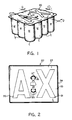
- Fig. 1 is a perspective view of a container package embodying the invention.
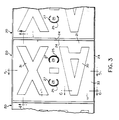
- Fig. 2 is a plan view of the carrier utilized in the package as shown in Fig. 1.
- Fig. 3 is a plan view of the portion of a roll of carriers utilized in the package.
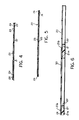
- Fig. 4 is a longitudinal sectional view taken along the line 4-4 in Fig. 3.
- Fig. 5 is a longitudinal sectional view through the package taken along the line 5-5 in Fig. 3.
- Fig. 6 is a fragmentary sectional view taken along the line 6-6 in Fig. 3.
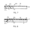
- Fig. 7 is a fragmentary sectional view on an enlarged scale of a portion of a modified form of the carrier.
- Fig. 8 is a fragmentary sectional view on an enlarged scale of a portion of a further modified form of carrier.
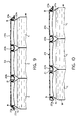
- Fig. 9 is a fragmentary longitudinal sectional view of a portion of a package taken along the line 9-9 in Fig. 1.
- Fig. 10 is a fragmentary sectional view of a portion of a package taken along the line 10-10 in Fig. 1.
- Fig. 11 is a schematic perspective view showing the making the carrier.
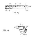
- Fig. 12 is a fragmentary sectional view on an enlarged scale of a portion of an additional form of carrier.
- Fig. 13 is a fragmentary sectional view of a portion of a package utilizing the carrier shown in Fig. 12.
- Referring to Fig. 1, the container package embodying the invention comprises a
carrier 20 including a plurality or array of containers C, such as 12 cans, supported so the side wall W of the containers C are in adjacent abutting relation. As is common in cans, the cans include an annular chime or bead B that is connected to the side wall W by a tapered neck portion N. - Referring to Figs. 2-6, the
carrier 20 comprises asheet 21 which is preferably made of relatively stiff flexible plastic of uniform thickness which is generally rectangular and has a plurality ofopenings 22 corresponding in number to the number of cans for the package, preferably twelve. Theopenings 22 have a cross sectional area slightly less then the diameter of the cans below the bead B. As shown, theopenings 22 are circular. - The
carrier 20 further includes a relativelythin film 23 which is thinner then thesheet 21 and is coextensive with thesheet 21 and bonded about theperiphery 24. The bonding at the periphery of the lines is preferably by heat. Thecarrier 20 further includes portions partially cut to formarcuate slots 25 in thefilm 23 andsheet 21 to define tabs 26 (Fig. 2), each of which comprises a layer of plastic from thecarrier sheet 21 and a layer of plastic from thefilm 23.Tabs 26 are adapted to be bent downwardly to provide openings to receive the fingers of a hand in order to lift and carry the package, the openings being preferably spaced transversely of one another.Arcuate bonding lines 27 are provided about the periphery of the tabs thetabs 26 minimizing the likelihood of detachment of the film from the sheet at the tabs. - As shown in Figs. 9 and 10, when the
carrier 20 is applied to the cans either by progressively forcing the carrier downwardly onto an array of cans from one end of the array to the other or by simultaneously forcing the carrier downwardly onto the array, theportions 22a of the periphery of theopenings 22 are flexed upwardly about the beads B of the cans C and then flexed radially inwardly below the beads B. It may be noted that the periphery of the portion of the carriers surrounding the opening flexes only sufficiently to extend upwardly beneath the bead but preferably not such that it is stretched and engages and conforms to the neck N of the can C as occurs in conventional ring type can carriers. Such ring type carriers that are commercially used at the present time are shown in the aforementioned patents 3,874,502, 4,219,177 and 4,586,742. - In a longitudinal direction, the
film 23 is flexed about the upper ends of the cans so that theportion 23a of the film at the periphery is inclined upwardly and inwardly toward the tops of the peripheral cans and the remainder of the film between the peripheral edges in the longitudinal direction is taut and extends generally parallel to thesheet 21 or horizontally when the package is on a horizontal surface. Theentire portion 23b overlying the cans is taut and extends horizontally. Similarly in a transverse direction, thefilm portions 23a at the periphery are also inclined upwardly and inwardly toward the tops of the cans and theportion 23b. Theentire portion 23b of the film over the tops of the cans is taut and extends horizontally. - As shown in Fig. 2, the
indicia other markings 33 or background may be applied by printing on the outer surface of thefilm 23. Alternatively, the indicia may comprise an opaque color to the film or sheet. - It has been found that the
film 23 is substantially uniformly stretched from one peripheral edge to the opposite peripheral edge. As a result, the indicia can be applied over the entire surface of the carrier without unsightly distortion of the indicia by the stretching of thefilm 23 during application. - In a form of
carrier 20 shown in Fig. 7,film 35 is transparent and theindicia 36 are provided on the underside of thefilm 35. In all other respects this form is constructed like that shown in Figs. 1-6. This form has the advantage of protecting the indicia from scuffing when packages are handled or stacked on one another for shipping or display. - In the form of
carrier 20b shown in Fig. 8, the film comprised an outer transparent film layer 40 havingindicia 43 on the underside of layer 40 and aninner film layer 41. Theindicia 43 are formed on the inner surface oflayer 40 or 41. An adhesive 42 may be provided to bond the two layers to one another to form a single film. - It can thus be seen that where the indicia are provided on the underside of the film, they are less subjected to abrasive action of the cans on another package during the application to the cans, normal handling, storage and stacking of one package on another. Where the indicia are provided between two layers of film, abrasive action of the printing ink with the upper ends of the cans in the package, which might mar the indicia, is obviated.
- In the form of the carrier shown in Figs. 9 and 10, the
carrier 20c is similar to that shown in Fig. 8 except that thetransparent layer 40a having indicia on the underside and film layer 41 a are not bonded by an adhesive to one another. By this arrangement, when the carrier is applied to the array of cans, theouter film layer 40a and the inner film layer 41 a can slide or move relative to one another minimizing any tendency to deform or mar theindicia 43a during application of the carrier to the cans. - The aforementioned constructions are disclosed in the aforementioned patent 4,911,290 that is incorporated herein by reference.
- In accordance with the invention, in each of the forms of the invention, the
sheet 21 comprises two coextruded layers, a relatively stiffflexible plastic layer 21 a of uniform thickness and a second layer 21 b coextruded with the first layer and being substantially thinner than the first layer and bonded to the film or films. Further, the coextruded second layer 21 b has a melting point less than that of thefirst layer 21 a and less than that of the film or films which are bonded to thesheet 21. - In accordance with the invention, the first
thick layer 21 a of plastic is substantially thicker than the second layer 21 b and the film or films bonded to the sheet are thicker than the second coextruded layer. - In a preferred example, the sheet comprises high density polyethylene as the
first layer 21 a and ultra low density polyethylene as the coextruded layer 21 b and the film or films comprise an outer film or films having a total thickness of 2.5 mils. Where no films are used, the outer layer having a thickness of 1.5 mils, the inner layer having a thickness of 1 mil, and the coextruded layer 21 b having a thickness of at least 0.5 mil but preferably 0.75 mil while the sheet has a thickness of 13.5 mils. Satisfactory result from the standpoint of bonding of the films to the coextruded sheet are achieved with such a sheet. - Specifically, in a preferred form, the
first layer 21 a of the coextruded sheet has a thickness of 13.50 mil and comprises high density polyethylene having a melting point of 135°C, density of 0.960 and a melt index of 0.3, made by Allied Signal Inc., and sold under the designation Paxon AA60-003; the coextruded layer having a thickness of 0.75 mil comprises ultra low density polyethylene having a melting point of 105-110 F and a softening point of about 90 F, density of 0.905 and a melt index of 0.8, made by Dow Chemical Company and sold under the designation Attane 4003; an intermediate film having a thickness of 1 mil and comprising an ultra low density polyethylene having a melting point of 120° F, a density of 0.912 and a melt index of 3.3 and sold by Dow Chemical Company under the designation Attane 4004; and the top film layer comprises a linear low density polyethylene layer having a melting point of 128° F and a thickness of 1.5 mil, a density of 0.920, a melt index of 1 and sold by Dow Chemical Company under the designation Dowlex 2045. - Alternatively, EVA, EEA and other low melting copolymers may be used as the coextruded layer.
- Referring to Fig. 11, the carriers are preferably formed by first forming a strip S with
openings 22 and feeding the strip S and a web of film F from a roll between aheated roller 45 that has longitudinalheated ribs 46 that bond the film to a strip of carriers along theperiphery 24. Transverse ribs 47 comprise spaced ribs thereby defining separate carriers that can be severed. The transverse ribs 47 comprise ribs of double widths so that when the carriers are subsequently cut from the web, a desiredperipheral edge 24 is provided.Roll 45 includedarcuate bonding portions 48 for bonding the portions from whichtabs 26 are to be formed. - The web of carriers are then passed through a
die cutting roll 49 which includes cuttingedges 49a that trim the side edges, cuttingportions 49b that trim the corners, and cutting edges 49c that simultaneously form thefiner tabs 26. - By this method, a roll R of carriers is provided that can then be applied to successive arrays of the cans.
- It can thus be seen that a carrier has been provided which can be made rapidly at high speeds without melting and burning through the film; which produces a proper bond of the film to the sheet strip; and which is produced by method that obviates the aforementioned problems.
Claims (14)
1. The method of making a carrier for a container package for cans having a top, a peripheral bead, a side wall and an inclined portion extending upwardly and inwardly toward the bead, said method comprising
coextruding a web of coextruded plastic comprising a first layer and a second layer, said second layer having a melting point less than that of said first layer,
forming said web into a plurality of interconnected sheet portions of flexible plastic material, each sheet portion having a plurality of openings for receiving the upper ends of the cans, and
successively heat bonding at least one film of plastic material at the isolated areas to the upper surfaces of each sheet portion of said to form a continuous laminated web of carriers of film and sheet portions,
said second layer of the coextruded plastic web having a melting point less than that of said film.
2. The method set forth in claim 1 wherein said step of extruding said coextruded web is such that said first layer of said web has a thickness greater than said second layer.
3. The method set forth in claim 2 wherein said web has a thickness greater than that of said film and said film has a thickness greater than second layer of said coextruded web.
4. The method set forth in claim 1 including the step of interposing an intermediate film layer interposed between said first-mentioned film layer and said carrier and simultaneously bonding said intermediate layer at said isolated areas, said second layer of said web having a melting point less than that of said intermediate layer.
5. The method set forth in claim 4 wherein said step of extruding said coextruded web is such that said first layer of said web has a thickness greater than said second layer.
6. The method set forth in claim 5 wherein said web has a thickness greater than the thickness of said films and said films have a thickness greater than said second layer of said web.
7. The method set forth in any of claims 1-6 wherein said second layer of said coextruded web has a thickness of at least 0.5 mils.
8. The method set forth in any of claims 1-6 wherein said bonding is at the side edges and transversely of each sheet portion.
9. A carrier for a container package holding an array of cans, each of which has an annular bead on the upper end thereof comprising
a sheet of flexible plastic material having a plurality of openings forming an array for receiving the ends of the cans and at least one film of plastic material coextensive with said sheet and bonded to isolated portions of said sheet,
said sheet being made as a coextruded sheet comprising a first layer and second layer,
said second layer having a melting point lower than that of said first layer or said film thereby facilitating the bonding of the film to the sheet by heat.
10. The carrier set forth in claim 9 wherein said first layer of said sheet carrier has a thickness greater than said second layer.
11. The carrier set forth in claim 10 wherein said sheet has a thickness greater than that of said film and said film has a thickness greater than second layer of said coextruded web.
12. The carrier set forth in claim 11 wherein said second layer of said coextruded web has a thickness of at least 0.5 mils.
13. The carrier set forth in claim 9 including a second film interposed between said sheet and said first-mentioned film and heat bonded thereto at said isolated portions, said second layer having a melting point lower than that of said second film.
14. The carrier set forth in any one of claims 9-13 including an array of cans, each of which has an annular bead on the upper end thereof, said openings in said sheet of flexible material receiving the ends of the cans.
Applications Claiming Priority (2)
| Application Number | Priority Date | Filing Date | Title |
|---|---|---|---|
| US07/541,644 US5065862A (en) | 1990-06-21 | 1990-06-21 | Plastic can carrier and method of making |
| US541644 | 1990-06-21 |
Publications (1)
| Publication Number | Publication Date |
|---|---|
| EP0465833A1 true EP0465833A1 (en) | 1992-01-15 |
Family
ID=24160462
Family Applications (1)
| Application Number | Title | Priority Date | Filing Date |
|---|---|---|---|
| EP91109295A Withdrawn EP0465833A1 (en) | 1990-06-21 | 1991-06-06 | Plastic can carrier and method of making |
Country Status (2)
| Country | Link |
|---|---|
| US (1) | US5065862A (en) |
| EP (1) | EP0465833A1 (en) |
Cited By (3)
| Publication number | Priority date | Publication date | Assignee | Title |
|---|---|---|---|---|
| DE9416552U1 (en) * | 1994-10-14 | 1995-03-16 | Kemper Gmbh & Co H | Packaging unit with receptacles for food |
| WO1999000777A1 (en) * | 1997-06-30 | 1999-01-07 | The Coca-Cola Company | Vending machine to select composition of pack and its method of use |
| WO2002081324A1 (en) | 2001-04-05 | 2002-10-17 | J. L. Corp. | Element for carrying cans or similar products and a blank for making one such element |
Families Citing this family (30)
| Publication number | Priority date | Publication date | Assignee | Title |
|---|---|---|---|---|
| US5861201A (en) * | 1994-02-15 | 1999-01-19 | Owens-Illinois Labels Inc. | Multilayer label material |
| US5441147A (en) * | 1994-05-31 | 1995-08-15 | Tanner; Bernard | Plastic packaging collars for drink cans |
| US5647497A (en) * | 1996-02-21 | 1997-07-15 | Labbe; Andre | Protective removable cover for beverage container |
| US6598738B2 (en) | 1998-09-25 | 2003-07-29 | Illinois Tool Works Inc. | Multiple property container carrier |
| US6006902A (en) | 1998-09-25 | 1999-12-28 | Illinois Tool Works Inc. | Multiple modules container carrier |
| WO2020051423A2 (en) | 2018-09-07 | 2020-03-12 | Graphic Packaging International, Llc | Package for containers |
| USD946420S1 (en) * | 2020-06-30 | 2022-03-22 | Graphic Packaging International, Llc | Carrier |
| US11180301B2 (en) | 2018-12-14 | 2021-11-23 | Graphic Packaging International, Llc | Carrier for containers |
| US11261013B2 (en) | 2018-12-14 | 2022-03-01 | Graphic Packaging International, Llc | Carrier for containers |
| US11623803B2 (en) | 2018-12-14 | 2023-04-11 | Graphic Packaging International, Llc | Carrier for containers |
| US11014727B2 (en) | 2018-12-14 | 2021-05-25 | Graphic Packaging International, Llc | Carrier for containers |
| US11027904B2 (en) | 2018-12-14 | 2021-06-08 | Graphic Packaging International, Llc | Carrier for containers |
| USD946419S1 (en) | 2020-06-30 | 2022-03-22 | Graphic Packaging International, Llc | Carrier |
| USD946421S1 (en) * | 2018-12-14 | 2022-03-22 | Graphic Packaging International, Llc | Carrier |
| CA3136696A1 (en) * | 2019-04-11 | 2020-10-15 | Westrock Packaging Systems, Llc | Article top engaging device, article carrier and blank therfor |
| USD984280S1 (en) | 2019-05-30 | 2023-04-25 | Graphic Packaging International, Llc | Carrier |
| USD984279S1 (en) | 2019-05-30 | 2023-04-25 | Graphic Packaging International, Llc | Carrier |
| USD974923S1 (en) | 2019-05-30 | 2023-01-10 | Graphic Packaging International, Llc | Carrier |
| TW202128519A (en) * | 2019-07-08 | 2021-08-01 | 美商偉斯特洛克包裝系統有限責任公司 | Article carrier and blank therfor |
| DE102020109628A1 (en) * | 2020-04-07 | 2021-10-07 | Krones Aktiengesellschaft | Packaging unit, packaging device and method for producing packaging units |
| USD946417S1 (en) | 2020-06-30 | 2022-03-22 | Graphic Packaging International, Llc | Carrier |
| USD946418S1 (en) * | 2020-04-27 | 2022-03-22 | Graphic Packaging International, Llc | Carrier |
| USD984281S1 (en) | 2020-04-27 | 2023-04-25 | Graphic Packaging International, Llc | Carrier |
| CN116323421A (en) | 2020-09-30 | 2023-06-23 | 印刷包装国际有限责任公司 | Carrier for containers |
| USD983049S1 (en) | 2021-03-24 | 2023-04-11 | Graphic Packaging International, Llc | Carrier for containers |
| USD984282S1 (en) | 2021-03-24 | 2023-04-25 | Graphic Packaging International, Llc | Carrier for containers |
| USD1000290S1 (en) | 2021-03-24 | 2023-10-03 | Graphic Packaging International, Llc | Carrier for containers |
| USD984266S1 (en) | 2021-03-24 | 2023-04-25 | Graphic Packaging International, Llc | Carrier for containers |
| BR112023023220A2 (en) | 2021-06-09 | 2024-01-30 | Graphic Packaging Int Llc | CONVEYOR FOR CONTAINING A PLURALITY OF CONTAINERS, BULL PART FOR FORMING A CONVEYOR FOR CONTAINING A PLURALITY OF CONTAINERS, METHOD FOR FORMING A CONVEYOR FOR CONTAINING A PLURALITY OF CONTAINERS, AND PACKAGING |
| KR20240036603A (en) | 2021-07-15 | 2024-03-20 | 그래픽 팩키징 인터내셔날, 엘엘씨 | Carrier for containers |
Citations (1)
| Publication number | Priority date | Publication date | Assignee | Title |
|---|---|---|---|---|
| US3317234A (en) * | 1965-05-24 | 1967-05-02 | James C De Shazor Jr | Carrier for bottles or cans |
Family Cites Families (17)
| Publication number | Priority date | Publication date | Assignee | Title |
|---|---|---|---|---|
| US3200944A (en) * | 1961-05-26 | 1965-08-17 | Illinois Tool Works | Container package |
| US3601439A (en) * | 1969-06-06 | 1971-08-24 | Illinois Tool Works | Container-packaging device |
| US3627121A (en) * | 1970-01-05 | 1971-12-14 | Illinois Tool Works | Covered top container carrier |
| US3882219A (en) * | 1971-03-29 | 1975-05-06 | Cosden Oil & Chem Co | Co-extrusion of acrylic ester polymer/polystyrene multiple-layered sheeting |
| US3874502A (en) * | 1973-03-02 | 1975-04-01 | Illinois Tool Works | Multiple container carrier and package |
| US4018027A (en) * | 1975-06-02 | 1977-04-19 | Byron V. Curry et al. | Heat installed multi-pack carrier machine |
| US4586742A (en) * | 1978-08-07 | 1986-05-06 | Lew Jung G | Sanitary ring packaging |
| US4724655A (en) * | 1978-08-07 | 1988-02-16 | Lew Jung G | Sanitary ring packaging |
| DE2966073D1 (en) * | 1978-10-23 | 1983-09-22 | Ici Plc | Method of making laminates of thermoplastic polymers by a single-channel coextrusion process and melt injector block for use therein |
| US4219117A (en) * | 1979-04-18 | 1980-08-26 | Illinois Tool Works Inc. | Multipackaging device |
| US4289236A (en) * | 1979-09-26 | 1981-09-15 | Ganz Brothers, Inc. | Case can package and method of forming same |
| US4385690A (en) * | 1981-11-25 | 1983-05-31 | Illinois Tool Works Inc. | Package unit carrier |
| US4385691A (en) * | 1981-11-25 | 1983-05-31 | Illinois Tool Works Inc. | Package unit carrier |
| US4501104A (en) * | 1982-09-10 | 1985-02-26 | Metal Box, P.L.C. | Multipacks of containers |
| US4471010A (en) * | 1983-10-18 | 1984-09-11 | Illinois Tool Works Inc. | Splice for multi-packaging device |
| US4520924A (en) * | 1984-04-27 | 1985-06-04 | Illinois Tool Works Inc. | Multi-package and packaging device |
| US4592466A (en) * | 1985-03-25 | 1986-06-03 | Illinois Tool Works Inc. | Container carrier and package |
-
1990
- 1990-06-21 US US07/541,644 patent/US5065862A/en not_active Expired - Fee Related
-
1991
- 1991-06-06 EP EP91109295A patent/EP0465833A1/en not_active Withdrawn
Patent Citations (1)
| Publication number | Priority date | Publication date | Assignee | Title |
|---|---|---|---|---|
| US3317234A (en) * | 1965-05-24 | 1967-05-02 | James C De Shazor Jr | Carrier for bottles or cans |
Cited By (5)
| Publication number | Priority date | Publication date | Assignee | Title |
|---|---|---|---|---|
| DE9416552U1 (en) * | 1994-10-14 | 1995-03-16 | Kemper Gmbh & Co H | Packaging unit with receptacles for food |
| WO1999000777A1 (en) * | 1997-06-30 | 1999-01-07 | The Coca-Cola Company | Vending machine to select composition of pack and its method of use |
| US6112497A (en) * | 1997-06-30 | 2000-09-05 | The Coca-Cola Company | Variety pack vendor and method of using |
| EP1939824A1 (en) * | 1997-06-30 | 2008-07-02 | The Coca-Cola Company | Vending machine to select composition of pack and its method of use |
| WO2002081324A1 (en) | 2001-04-05 | 2002-10-17 | J. L. Corp. | Element for carrying cans or similar products and a blank for making one such element |
Also Published As
| Publication number | Publication date |
|---|---|
| US5065862A (en) | 1991-11-19 |
Similar Documents
| Publication | Publication Date | Title |
|---|---|---|
| US5065862A (en) | Plastic can carrier and method of making | |
| CN1079772C (en) | Two-piece fused top lift carrier | |
| US6145656A (en) | Film multipackage | |
| US5358804A (en) | Multilayer adhesive label | |
| US4333570A (en) | Merchandising package for containers | |
| US5324559A (en) | Booklet label and method for making the same | |
| CN1059869C (en) | Container carrier | |
| EP1013564B1 (en) | Film multipackage | |
| US5474172A (en) | Paperboard bottle carrier with handle | |
| US4911290A (en) | Container package | |
| US4649007A (en) | Coextruded multiple plastic layer slip pallet | |
| EP0386399A1 (en) | Container package | |
| US4555290A (en) | Method of making cassette holders | |
| EP0196181A3 (en) | Container carrier and package | |
| CN101102941A (en) | Sleeved container package with opening feature | |
| CN1683217A (en) | Top lift carrier and method of manufacture therefor | |
| JP4293517B2 (en) | Shading container | |
| US4815589A (en) | Can package | |
| US4632717A (en) | Method of making book style albums | |
| CA1113047A (en) | Merchandising package for containers | |
| JP3887516B2 (en) | Heat shrink label continuum | |
| US20010025800A1 (en) | Film Multipackage | |
| JP3859843B2 (en) | Heat sealing lid material | |
| JP2009029521A (en) | Container package | |
| WO2023091622A1 (en) | Label sheet assembly and method for peek a boo label |
Legal Events
| Date | Code | Title | Description |
|---|---|---|---|
| PUAI | Public reference made under article 153(3) epc to a published international application that has entered the european phase |
Free format text: ORIGINAL CODE: 0009012 |
|
| AK | Designated contracting states |
Kind code of ref document: A1 Designated state(s): AT BE CH DE DK ES FR GB GR IT LI LU NL SE |
|
| 17P | Request for examination filed |
Effective date: 19920615 |
|
| 17Q | First examination report despatched |
Effective date: 19940407 |
|
| STAA | Information on the status of an ep patent application or granted ep patent |
Free format text: STATUS: THE APPLICATION IS DEEMED TO BE WITHDRAWN |
|
| 18D | Application deemed to be withdrawn |
Effective date: 19940818 |