EP0465896A1 - Connector device for corrugated pipe and hose - Google Patents
Connector device for corrugated pipe and hose Download PDFInfo
- Publication number
- EP0465896A1 EP0465896A1 EP91110244A EP91110244A EP0465896A1 EP 0465896 A1 EP0465896 A1 EP 0465896A1 EP 91110244 A EP91110244 A EP 91110244A EP 91110244 A EP91110244 A EP 91110244A EP 0465896 A1 EP0465896 A1 EP 0465896A1
- Authority
- EP
- European Patent Office
- Prior art keywords
- ring
- housing
- hose
- connecting element
- locking
- Prior art date
- Legal status (The legal status is an assumption and is not a legal conclusion. Google has not performed a legal analysis and makes no representation as to the accuracy of the status listed.)
- Granted
Links
- 210000000078 claw Anatomy 0.000 claims abstract description 35
- 238000007789 sealing Methods 0.000 claims description 12
- 238000004873 anchoring Methods 0.000 description 1
- 230000007423 decrease Effects 0.000 description 1
- 230000001419 dependent effect Effects 0.000 description 1
- 210000004072 lung Anatomy 0.000 description 1
- 238000000034 method Methods 0.000 description 1
Images


Classifications
-
- F—MECHANICAL ENGINEERING; LIGHTING; HEATING; WEAPONS; BLASTING
- F16—ENGINEERING ELEMENTS AND UNITS; GENERAL MEASURES FOR PRODUCING AND MAINTAINING EFFECTIVE FUNCTIONING OF MACHINES OR INSTALLATIONS; THERMAL INSULATION IN GENERAL
- F16L—PIPES; JOINTS OR FITTINGS FOR PIPES; SUPPORTS FOR PIPES, CABLES OR PROTECTIVE TUBING; MEANS FOR THERMAL INSULATION IN GENERAL
- F16L33/00—Arrangements for connecting hoses to rigid members; Rigid hose connectors, i.e. single members engaging both hoses
- F16L33/22—Arrangements for connecting hoses to rigid members; Rigid hose connectors, i.e. single members engaging both hoses with means not mentioned in the preceding groups for gripping the hose between inner and outer parts
-
- F—MECHANICAL ENGINEERING; LIGHTING; HEATING; WEAPONS; BLASTING
- F16—ENGINEERING ELEMENTS AND UNITS; GENERAL MEASURES FOR PRODUCING AND MAINTAINING EFFECTIVE FUNCTIONING OF MACHINES OR INSTALLATIONS; THERMAL INSULATION IN GENERAL
- F16L—PIPES; JOINTS OR FITTINGS FOR PIPES; SUPPORTS FOR PIPES, CABLES OR PROTECTIVE TUBING; MEANS FOR THERMAL INSULATION IN GENERAL
- F16L25/00—Constructive types of pipe joints not provided for in groups F16L13/00 - F16L23/00 ; Details of pipe joints not otherwise provided for, e.g. electrically conducting or insulating means
- F16L25/0036—Joints for corrugated pipes
- F16L25/0045—Joints for corrugated pipes of the quick-acting type
-
- F—MECHANICAL ENGINEERING; LIGHTING; HEATING; WEAPONS; BLASTING
- F16—ENGINEERING ELEMENTS AND UNITS; GENERAL MEASURES FOR PRODUCING AND MAINTAINING EFFECTIVE FUNCTIONING OF MACHINES OR INSTALLATIONS; THERMAL INSULATION IN GENERAL
- F16L—PIPES; JOINTS OR FITTINGS FOR PIPES; SUPPORTS FOR PIPES, CABLES OR PROTECTIVE TUBING; MEANS FOR THERMAL INSULATION IN GENERAL
- F16L37/00—Couplings of the quick-acting type
- F16L37/08—Couplings of the quick-acting type in which the connection between abutting or axially overlapping ends is maintained by locking members
- F16L37/084—Couplings of the quick-acting type in which the connection between abutting or axially overlapping ends is maintained by locking members combined with automatic locking
- F16L37/098—Couplings of the quick-acting type in which the connection between abutting or axially overlapping ends is maintained by locking members combined with automatic locking by means of flexible hooks
- F16L37/0985—Couplings of the quick-acting type in which the connection between abutting or axially overlapping ends is maintained by locking members combined with automatic locking by means of flexible hooks the flexible hook extending radially inwardly from an outer part and engaging a bead, recess or the like on an inner part
-
- Y—GENERAL TAGGING OF NEW TECHNOLOGICAL DEVELOPMENTS; GENERAL TAGGING OF CROSS-SECTIONAL TECHNOLOGIES SPANNING OVER SEVERAL SECTIONS OF THE IPC; TECHNICAL SUBJECTS COVERED BY FORMER USPC CROSS-REFERENCE ART COLLECTIONS [XRACs] AND DIGESTS
- Y10—TECHNICAL SUBJECTS COVERED BY FORMER USPC
- Y10S—TECHNICAL SUBJECTS COVERED BY FORMER USPC CROSS-REFERENCE ART COLLECTIONS [XRACs] AND DIGESTS
- Y10S285/00—Pipe joints or couplings
- Y10S285/903—Corrugated
-
- Y—GENERAL TAGGING OF NEW TECHNOLOGICAL DEVELOPMENTS; GENERAL TAGGING OF CROSS-SECTIONAL TECHNOLOGIES SPANNING OVER SEVERAL SECTIONS OF THE IPC; TECHNICAL SUBJECTS COVERED BY FORMER USPC CROSS-REFERENCE ART COLLECTIONS [XRACs] AND DIGESTS
- Y10—TECHNICAL SUBJECTS COVERED BY FORMER USPC
- Y10S—TECHNICAL SUBJECTS COVERED BY FORMER USPC CROSS-REFERENCE ART COLLECTIONS [XRACs] AND DIGESTS
- Y10S285/00—Pipe joints or couplings
- Y10S285/921—Snap-fit
Definitions
- the invention relates to a connecting element for corrugated pipes and hoses with a parallel corrugated hose wall with the features of the preamble of claim 1.
- a connecting element of the type mentioned is e.g. known from EP 0 331 116 A1.
- a hose screw connection it comprises an approximately cylindrical housing with a connector with an external thread and has a plurality of window-like openings arranged in a radial plane in the housing wall. To connect the pipe or.
- a support ring is provided inside the housing, which consists of a stop ring and legs that can be attached to the front of the housing, which reach into the interior of the housing and fix the corrugated tube or the hose in the area of the window-like openings with locking claws at their free ends Connect the corrugated pipes or hoses to the desired depth in the housing, whereupon the locking claws snap into one of the grooves in the corrugated pipe or hose and prevent loosening by contacting the inner edges of the window-like openings. Anchoring the corrugated pipes and hoses in the connecting elements is therefore extremely simple and uncomplicated, but loosening is not possible again.
- the invention is therefore based on the object of designing connecting elements of the type mentioned in such a way that the corrugated pipes or hoses can also be detached in a simple and uncomplicated manner.
- the invention provides that the support ring in the form of a sliding sleeve consisting of a stop ring, an axially spaced inner ring, webs connecting the stop ring and the inner ring, and legs with the locking elements extending from the inner ring to the stop ring. lung claws at their free ends.
- the locking claws which escape into the window-like openings when they are joined can also escape into the window-like openings when the corrugated tube or hose is removed.
- the inner ring carries the locking claws on the legs directed towards the stop ring and their pivot axes or articulation points cause the locking claws to pivot in a direction opposite to that according to the prior art with a similar direction of force.
- the locking claws and correspondingly the legs carrying them when pulling the corrugated tube or hose contrary to the situation in the prior art, are not subjected to pressure, but rather to tension, which also favors evasion of the locking claws in the window-like openings.
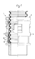
- a connecting element 1 for corrugated pipes and hoses 2 with parallel corrugated hose wall 3 consists of an approximately cylindrical housing 4 and a sliding sleeve 5.
- the housing 4 has a connecting piece 6 e.g. in the form of a thread and in the housing wall 7 a plurality of window-like openings 8.
- a shoulder forming an annular surface 9 is provided inside the housing 4, on which a spring-elastic sealing ring 10 is arranged.
- this sealing ring 10 consists of an L-shaped ring body, the disc part 11 of which rests on the ring surface 9, while its cylinder part 12 extends in the axial direction.
- the dimensions of the disc part 11 and the cylinder part 12 are also selected 50 so that the hose 2 can rest with its free end 13 on the disc part 11, while the cylinder part 12 encompasses the free hose end.
- the sliding sleeve 5 comprises a stop ring 14 which is arranged on the outside on the end face of the housing end 15 facing away from the connecting piece 6 of the housing 4 and distributed along its circumference and carries a plurality of webs 16 at a distance from one another. These webs 16 extend axially inward from the stop ring 14 into the interior of the cylindrical housing 4 and lie there in each case next to the window-like openings 8. In the interior of the housing 4, the webs 16 carry an inner ring 17 which, with its free end face 18, rests on the resilient one Sealing ring 1o rests. Finally, on the inner ring 17 are Schen kel 19 arranged and extend between the webs 16 to the stop ring 14. The free end of each leg 19 is designed as a locking claw 2o, which produces both a locking with the corrugated tube or the corrugated hose 2 and with the window-like opening 8 of the housing 4.
- the immediately adjacent to the inner ring 17 of the leg portion 19 serves as a bearing or as a hinge for both radially inwardly and radially outwardly pivotable lock claw 2 0th
- the locking claws 2o can therefore be pivoted about an articulation point facing the end 13 of the corrugated tube or hose 2.
- the hinge point is created by reducing the material cross section of the legs 19 directly on the inner ring 17.
- each locking claw 2o Towards its free end 21, each locking claw 2o has a radially inwardly directed inner bevel surface 22 and a radially outwardly directed outer bevel surface 23.
- each locking claw 2o Towards its free end 21, each locking claw 2o has a radially inwardly directed inner bevel surface 22 and a radially outwardly directed outer bevel surface 23.
- the corrugated tube or hose 2 can therefore be attached to the claw 20 according to FIG. 1 Slide past until the free end 13 of the corrugated tube or hose 2 meets the sealing ring 1.
- a locking projection 24 is formed by the inner inclined surface 22 and a shoulder 25 on the inside of the locking claw and engages in the groove 26 of the corrugated tube or hose 2 lying in front of it in each case (FIG. 1).
- the outer inclined surface 23 merges into an exclusively radially outwardly directed stop surface 28. It forms together with a merging into the leg 19 of connector 29 has an outwardly directed latching projection 3 0th
- the spring-elastic sealing ring 1o is dimensioned such that it presses the sliding sleeve 5 with the outer inclined surfaces 23 on the locking claws 2o against the inner edges 31 of the window-like openings 8.
- the stop ring 14 of the sliding sleeve 5 with its end face 32 on the housing side moves a certain distance from the end 15 of the housing 4 (FIG. 3). In this position, too, the sealing ring 10 is still compressed and, as a result, is slightly deformed radially inwards slightly in the region of its free end 33 (FIG. 3).
- the locking claw swivels from its position in the opening 8 clockwise according to FIG. 1 and is located so in a locking position.
- the corrugated pipe or the hose 2 can now no longer detach itself automatically from the connecting element 1.
- the sealing ring 1o now pushes the sliding sleeve 5 into the position shown in FIG. 2, in which the free end 21 of the locking claw engages behind the inner edge 31 of the window-like opening 8.
- the stop ring 14 is now at a distance from the free end 15 of the housing 4.
- the sliding sleeve To release, the sliding sleeve must first be moved axially inwards into the housing 4 together with the corrugated tube or hose 2 against the force of the sealing ring 1o until the free ends 21 on the locking claws 2o are in front of the window-like openings 8 of the housing and the Can pivot locking claws 2o radially outwards. This happens as soon as the sliding sleeve 5 on the corrugated pipe or hose 2 is pushed inward so that the inclined surfaces which are necessarily present on the outside of the corrugated pipe or hose 2 press the locking claws 2o outwards. The connecting element 1 and the corrugated tube or hose 2 can thus be detached again.
Abstract
Description
Die Erfindung betrifft ein Verbindungselement für Wellrohre und Schläuche mit parallel gewellter Schlauchwand mit den Merkmalen des Oberbegriffes des Anspruches 1.The invention relates to a connecting element for corrugated pipes and hoses with a parallel corrugated hose wall with the features of the preamble of
Ein Verbindungselement der genannten Art ist z.B. aus dar EP o 331 116 A1 bekannt. Es umfasst als Schlauchverschraubung ein annähernd zylindrisches Gehäuse mit einem Anschlußstück mit Außengewinde und weist in der Gehäusewand mehrere, in einer Radialebene angeordnet, fensterartige Öffnungen auf. Zum Verbinden des Rohr-bzw. Schlauchendes innen in dem Gehäuse ist ein Tragring vorgesehen, der aus einem stirnseitig am Gehäuse anlegbaren Anschlagring und Schenkeln besteht,die in das Innere des Gehäuses greifen und mit Verriegelungskrallen an ihren freien Enden das Wellrohr bzw. den Schlauch im Bereich der fensterartigen Öffnungen fixieren.Zum Verbinden werden die Wellrohre oder Schläuche bis zur gewünschten Tiefe in das Gehäuse geschoben woraufhin die Verriegelungskrallen in eine der Rillen im Wellrohr bzw. Schlauch einrasten und ein Lösen durch Anlage an den Innenkanten der fensterartigen Öffnungen verhindern. Das Verankern der Wellrohre und Schläuche in den Verbindungselementen ist daher außerordentlich einfach und unkompliziert, ein Lösen ist jedoch nicht wieder möglich.A connecting element of the type mentioned is e.g. known from EP 0 331 116 A1. As a hose screw connection, it comprises an approximately cylindrical housing with a connector with an external thread and has a plurality of window-like openings arranged in a radial plane in the housing wall. To connect the pipe or. A support ring is provided inside the housing, which consists of a stop ring and legs that can be attached to the front of the housing, which reach into the interior of the housing and fix the corrugated tube or the hose in the area of the window-like openings with locking claws at their free ends Connect the corrugated pipes or hoses to the desired depth in the housing, whereupon the locking claws snap into one of the grooves in the corrugated pipe or hose and prevent loosening by contacting the inner edges of the window-like openings. Anchoring the corrugated pipes and hoses in the connecting elements is therefore extremely simple and uncomplicated, but loosening is not possible again.
Der Erfindung liegt daher die Aufgabe zugrunde, Verbindungselemente der genannten Art so zu gestalten, daß auch ein Lösen der Wellrohre bzw. Schläuche auf einfache und unkomplizierte Weise möglich ist.The invention is therefore based on the object of designing connecting elements of the type mentioned in such a way that the corrugated pipes or hoses can also be detached in a simple and uncomplicated manner.
Zur Lösung dieser Aufgabe sieht die Erfindung vor, daß der Tragring in Form einer Schiebemuffe aus einem Anschlagring, einem axial im Abstand dazu angeordneten Innenring, den Anschlagring und den Innenring verbindenden Stegen sowie sich vom Innenring zum An- schlagring hin erstreckenden Schenkeln mit den Verriege- lungskrallen an deren freien Enden besteht.To achieve this object, the invention provides that the support ring in the form of a sliding sleeve consisting of a stop ring, an axially spaced inner ring, webs connecting the stop ring and the inner ring, and legs with the locking elements extending from the inner ring to the stop ring. lung claws at their free ends.
Die beim Zusammenfügen in die fensterartigen Öffnungen ausweichenden Verriegelungskrallen können auf Grund der zusätzlichen Verwendung eines Innenringes, der als Träger für die Schenkel mit den Verriegelungskrallen dient, beim Abziehen des Wellrohres bzw. Schlauches ebenfalls in die fensterartigen Öffnungen ausweichen. Voraussetzung hierzu ist allerdings, daß die Schiebemuffe in das Gehäuse axial einwärts verschoben ist. Während beim Stand der Technik das abzuziehende Wellrohr bzw. der Schlauch auf die Verriegelungskrallen eine radial einwärts gerichtete Kraft ausübt, so daß ein Lösen unmöglich ist, werden die Verriegelungskrallen erfindungsgemäß beim Abziehvorgang radial auswärts beaufschlagt. Dies ist möglich, weil der Innenring an den zum Anschlagring hin gerichteten Schenkeln die Verriegelungskrallen trägt und deren Schwenkachsen bzw. Gelenkstellen bei einer gleichartigen Kraftrichtung ein Schwenken der Verriegelungskrallen in einer Richtung entgegengesetzt zu der nach dem Stand der Technik bewirkt. Auch werden die Verriegelungskrallen und entsprechend die sie tragenden Schenkel beim Abziehen des Wellrohres bzw. Schlauches entgegen der Situation beim Stand der Technik nicht auf Druck, sondern auf Zug belastet, wodurch ebenfalls ein Ausweichen der Verriegelungskrallen in den fensterartigen Öffnungen begünstigt wird.Due to the additional use of an inner ring, which serves as a support for the legs with the locking claws, the locking claws which escape into the window-like openings when they are joined can also escape into the window-like openings when the corrugated tube or hose is removed. The prerequisite for this, however, is that the sliding sleeve is displaced axially inwards into the housing. While in the prior art the corrugated tube to be removed or the hose exerts a radially inward force on the locking claws, so that loosening is impossible, the locking claws are acted upon radially outward during the pulling-off process. This is possible because the inner ring carries the locking claws on the legs directed towards the stop ring and their pivot axes or articulation points cause the locking claws to pivot in a direction opposite to that according to the prior art with a similar direction of force. Also, the locking claws and correspondingly the legs carrying them when pulling the corrugated tube or hose, contrary to the situation in the prior art, are not subjected to pressure, but rather to tension, which also favors evasion of the locking claws in the window-like openings.
Weitere Merkmale der Erfindung gehen aus Unteransprüchen im Zusammenhang mit der Zeichnung hervor.Further features of the invention emerge from dependent claims in connection with the drawing.
Die Erfindung wird nachstehend anhand eines Ausführungsbeispieles, das in der Zeichnung dargestellt ist, näher beschrieben. Dabei zeigen:
- Fig. 1: in größerem Maßstab und zum Teil geschnitten ein Verbindungselment mit einem vollständig eingeschobenen Ende eines Schlauches
- Fig. 2: eine Ansicht wie in Fig. 1, jedoch in verriegeltem Zustand.
- Fig. 3: eine Ansicht wie in den
Figuren 1 und 2, jedoch ohne Schlauch.
- Fig. 1: on a larger scale and partially cut a connecting element with a fully inserted end of a hose
- Fig. 2: a view as in Fig. 1, but in the locked state.
- Fig. 3: a view as in Figures 1 and 2, but without a hose.
Ein Verbindungselement 1 für Wellrohre und Schläuche 2 mit parallel gewellter Schlauchwand 3 besteht aus einem annähernd zylindrischen Gehäuse 4 und einer Schiebemuffe 5. Das Gehäuse 4 weist ein Anschlußstück 6 z.B. in Gestalt eines Gewindes sowie in der Gehäusewand 7 mehrere fensterartige Öffnungen 8 auf. Ferner ist innen im Gehäuse 4 ein eine Ringfläche 9 bildender Absatz vorgesehen, auf dem ein federelastischer Dichtungsring 1o angeordnet ist. Dieser Dichtungsring 1o besteht gemäß dem in den Figuren dargestellten Ausführungsbeispiel aus einem im Querschnitt L-förmigen Ringköprer, dessen Scheibenteil 11 auf der Ringfläche 9 aufliegt, während sich sein Zylinderteil 12 in axialer Richtung erstreckt. Die Abmessungen des Scheibenteiles 11 und des Zylinderteiles 12 sind dabei ferner 50 gewählt, daß der Schlauch 2 mit seinem freien Ende 13 auf dem Scheibenteil 11 aufliegen kann, während der Zylinderteil 12 das freie Schlauchende umgreift.A connecting
Die Schiebemuffe 5 umfasst einen Anschlagring 14, der stirnseitig außen an dem dem Anschlußstück 6 des Gehäuses 4 abgewandten Gehäuseende 15 angeordnet ist und an seinem Umfang verteilt sowie jeweils im Abstand voneinander mehrere Stege 16 trägt. Diese Stege 16 erstrecken sich von dem Anschlagring 14 axial einwärts in das Innere des zylindrischen Gehäuses 4 und liegen dort jeweils neben den fensterartigen Öffnungen 8. Im Inneren des Gehäuses 4 tragen die Stege 16 einen Innenring 17, der mit seiner freien Stirnfläche 18 an dem federelastischen Dichtungsring 1o anliegt. An dem Innenring 17 sind schließlich Schenkel 19 angeordnet und erstrekken sich zwischen den Stegen 16 zu dem Anschlagring 14 hin. Das freie Ende eines jeden Schenkels 19 ist als Verriegelungskralle 2o gestaltet, die sowohl eine Verriegelung mit dem Wellrohr bzw. dem gewellten Schlauch 2 als auch mit der fensterartigen Öffnung 8 des Gehäuses 4 herstellt.The sliding
Der unmittelbar an den Innenring 17 anschließende Teil des Schenkels 19 dient als Lagerstelle bzw. als Gelenk für die sowohl radial einwärts als auch radial auswärts verschwenkbare Verriegelungskralle 20. Die Verriegelungskrallen 2o sind daher um eine dem Ende 13 des Wellrohres bzw. Schlauches 2 zugewandte Gelenkstelle schwenkbar. Geschaffen wird die Gelenkstelle durch eine Verringerung des Materialquerschnitts der Schenkel 19 unmittelbar am Innenring 17.The immediately adjacent to the
Zu ihrem freien Ende 21 hin weist jede Verriegelungskralle 2o eine radial einwärts gerichtete Innenschrägfläche 22 und eine radial auswärts gerichtete Außenschrägfläche 23 auf. Beim Einführen des Wellrohres oder Schlauches 2 trifft dessen freies Ende 13 auf die Innenschrägfläche 22 der Verriegelungskralle 2o und drückt diese nach außen in den Freiraum der fensterartigen Öffnung 8. Das Wellrohr bzw. der Schlauch 2 läßt sich daher gemäß Fig. 1 an der Kralle 20 vorbeischieben, bis das freie Ende 13 des Wellrohres bzw. Schlauches 2 auf den Dichtungsring 1 trifft.Towards its
Ferner wird ein Rastvorsprung 24 von der Innenschrägfläche 22 und einem Absatz 25 auf der Innenseite der Verriegelungskralle gebildet und greift in die jeweils vor ihm liegende Rille 26 des Wellrohres bzw. Schlauches 2 ( Fig. 1).Furthermore, a
Die Außenschrägfläche 23 geht in eine ausschließlich radial auswärts gerichtete Anschlagfläche 28 über. Sie bildet zusammen mit einem in den Schenkel 19 übergehenden Verbindungsstück 29 einen nach außen gerichteten Rastvorsprung 30.The outer
Der federelastische Dichtungsring 1o ist, wie insbesondere aus Fig.3 hervorgeht, derart dimensioniert, daß er die Schiebemuffe 5 mit den Außenschrägflächen 23 an den Verriegelungskrallen 2o gegen die Innenkanten 31 der fensterartigen Öffnungen 8 drückt. Dabei entfernt sich der Anschlagring 14 der Schiebemuffe 5 mit seiner gehäuseseitigen Stirnfläche 32 ein gewisses Stück von dem Ende 15 des Gehäuses 4 (Fig.3 ). Auch in dieser Position ist der Dichtungsring 1o noch komprimiert und hierdurch geringfügig im Bereich seines freien Endes 33 geringfügig radial einwärts verformt (Fig.3 ). Wird nunmehr das freie Ende 13 eines Wellrohres oder Schlauches 2 durch den Anschlagring 14 der Schiebemuffe 5 in das Verbindungselement 1 einge- schoben, so stößt das freie Ende 13 auf die Innenschrägflächen 22 der Verriegelungskrallen 2o,schiebt bei weiterer axialer Bewegung die Schiebemuffe 5 gegen die Kraft des Dichtungsringes 1o axial vor sich her und drückt schließlich durch die Innenschrägflächen 22 die Verriegelungskrallen 2o in die fensterartigen Öffnungen 8, wodurch das Wellrohr bzw. der Schlauch 2 mit seinen Rillen 26 an den Rastvorsprüngen 24 vorbei bis zum scheibenförmigen Teil 11 des Dichtungsringes 1 geschoben werden kann. Sobald die vom Wellrohr oder Schlauch 2 auf die Verriegelungskrallen 2o ausgeübte Druckkraft nachlässt, und sich eine Rille 26 vor dem nach innen gerichteten Rastvorsprung 24 befindet, schwenkt die Verriegelungskralle aus ihrer Lage in der Öffnung 8 im Uhrzeigersinn gemäß Fig. 1 nach rechts und befindet sich damit in einer Verriegelungsposition. Das Wellrohr bzw. der Schlauch 2 kann sich jetzt selbsttätig nicht mehr aus dem Verbindungselement 1 lösen. Ferner drückt der Dichtungsring 1o die Schiebemuffe 5 nunmehr in die in Fig. 2 dargestellt Position, in der das freie Ende 21 der Verriegelungskralle die Innenkante 31 der fensterartigen Öffnung 8 hintergreift. Der Anschlagring 14 steht nun wiederum im Abstand von dem freien Ende 15 des Gehäuses 4.The spring-elastic sealing ring 1o, as can be seen in particular from FIG. 3, is dimensioned such that it presses the
Zum Lösen muß nunmehr die Schiebmuffe zunächst axial einwärts in das Gehäuse 4 zusammen mit dem Wellrohr bzw. Schlauch 2 gegen die Kraft des Dichtungsringes 1o verschoben werden, bis wiederum die freien Enden 21 an den Verriegelungskrallen 2o vor den fensterartigen Öffnungen 8 des Gehäuses stehen und die Verriegelungskrallen 2o radial auswärts schwenken können. Dies geschieht, sobald bei einwärts verschobener Schiebemuffe 5 am Wellrohr oder Schlauch 2 kräftig gezogen wird, so daß die außen am Wellrohr bzw. am Schlauch 2 notwendigerweise vorhandenen Schrägflächen die Verriegelungskrallen 2o nach außen drücken. Das Verbindungselement 1 und das Wellrohr bzw. der Schlauch 2 sind somit wieder lösbar.To release, the sliding sleeve must first be moved axially inwards into the
Claims (7)
Priority Applications (1)
| Application Number | Priority Date | Filing Date | Title |
|---|---|---|---|
| AT91110244T ATE100545T1 (en) | 1990-06-25 | 1991-06-21 | CONNECTING ELEMENT FOR CORRUGATED PIPES AND HOSES. |
Applications Claiming Priority (2)
| Application Number | Priority Date | Filing Date | Title |
|---|---|---|---|
| DE4020171 | 1990-06-25 | ||
| DE4020171A DE4020171C1 (en) | 1990-06-25 | 1990-06-25 |
Publications (2)
| Publication Number | Publication Date |
|---|---|
| EP0465896A1 true EP0465896A1 (en) | 1992-01-15 |
| EP0465896B1 EP0465896B1 (en) | 1994-01-19 |
Family
ID=6409021
Family Applications (1)
| Application Number | Title | Priority Date | Filing Date |
|---|---|---|---|
| EP91110244A Expired - Lifetime EP0465896B1 (en) | 1990-06-25 | 1991-06-21 | Connector device for corrugated pipe and hose |
Country Status (9)
| Country | Link |
|---|---|
| US (1) | US5112086A (en) |
| EP (1) | EP0465896B1 (en) |
| JP (1) | JPH0781661B2 (en) |
| KR (1) | KR960006179B1 (en) |
| AT (1) | ATE100545T1 (en) |
| CA (1) | CA2045268C (en) |
| DE (2) | DE4020171C1 (en) |
| ES (1) | ES2049063T3 (en) |
| HK (1) | HK91194A (en) |
Cited By (14)
| Publication number | Priority date | Publication date | Assignee | Title |
|---|---|---|---|---|
| EP0634600A1 (en) * | 1993-07-15 | 1995-01-18 | Pma Elektro Ag | Connector and fitting for corrugated pipes |
| DE4413346C1 (en) * | 1994-04-18 | 1995-08-17 | Rasmussen Gmbh | Push-in coupling for connecting two fluid pipes |
| DE19540280C1 (en) * | 1995-10-28 | 1997-03-20 | Balfo Verwaltungs Anstalt | Corrugated hose or profile pipe termination |
| DE19635986A1 (en) * | 1996-04-12 | 1997-10-16 | Lancomp Ag | Moulded flexible tube or hose with parallel peripheral grooves e.g. for protection of electrical conductors |
| EP0728977B1 (en) * | 1995-02-27 | 1999-12-08 | Interflex, S.A. | Connection device for corrugated pipes |
| WO2008064110A1 (en) * | 2006-11-21 | 2008-05-29 | Titeflex Corporation | Quick actuating fitting for corrugated stainless steel tubing |
| DE202009002925U1 (en) | 2009-02-23 | 2009-05-20 | Hidde, Axel R., Dr. | Conduit - / - pipe quick connector |
| DE202009007099U1 (en) | 2009-05-11 | 2009-08-06 | Hidde, Axel R., Dr. Ing. | Protective hose / pipe quick - fitting with front opener |
| WO2011006591A1 (en) * | 2009-07-14 | 2011-01-20 | Aft Automotive Gmbh & Co. Kg | Plug-in connector |
| CN101278147B (en) * | 2005-10-03 | 2012-05-09 | Pma股份公司 | Connection and joint piece for well tubes |
| DE102011085398A1 (en) | 2011-10-28 | 2013-05-02 | Fränkische Industrial Pipes GmbH & Co. KG | connecting unit |
| EP3043101A1 (en) * | 2015-01-08 | 2016-07-13 | Christoph Morach | Sealing sleeve |
| CN105782612A (en) * | 2016-05-18 | 2016-07-20 | 无锡市翱宇特新科技发展有限公司 | Pipeline connecting device |
| US10364924B2 (en) | 2014-09-22 | 2019-07-30 | Fränkische Industrial Pipes GmbH & Co. KG | Connecting assembly for a corrugated tube |
Families Citing this family (45)
| Publication number | Priority date | Publication date | Assignee | Title |
|---|---|---|---|---|
| US5332270A (en) * | 1987-04-09 | 1994-07-26 | Elconnex Pty Limited | Corrugated pipe connector and method of molding |
| US5626371A (en) * | 1990-01-16 | 1997-05-06 | Bartholomew; Donald D. | Quick connector with one-piece retainer |
| EP0545337B1 (en) * | 1991-11-29 | 1996-03-06 | Tokai Rubber Industries, Ltd. | Quick connector |
| DE4334529C2 (en) * | 1992-10-15 | 1996-06-13 | Furukawa Electric Co Ltd | Connection device for a flexible corrugated pipe |
| US5462311A (en) * | 1992-11-13 | 1995-10-31 | Royal Appliance Mfg. Co. | Telescoping wand for vacuum cleaners |
| FR2715454B1 (en) * | 1994-01-26 | 1996-04-12 | Caillau Ets | Quick connection. |
| US5803511A (en) * | 1995-05-30 | 1998-09-08 | Titeflex Corporation | Adaptors and method of attaching metal braid reinforced convoluted metal hoses to such adaptors |
| DE19523298A1 (en) * | 1995-06-27 | 1997-01-02 | Voss Armaturen | Plug connection for pressure medium lines |
| DE19540279A1 (en) * | 1995-10-28 | 1997-04-30 | Balfo Verwaltungs Anstalt | Connection piece for profile pipes, profile sockets, corrugated hoses or similar strands |
| DE29607470U1 (en) * | 1996-04-24 | 1996-08-29 | Reiku Gmbh | Coupling element for corrugated pipes |
| EP0965014B1 (en) * | 1997-03-07 | 2002-06-26 | Pma Ag | Joining and connecting element for corrugated pipes |
| DE19735491C1 (en) * | 1997-08-16 | 1998-07-16 | Rasmussen Gmbh | Coupling device for use with hose |
| GB9724521D0 (en) * | 1997-11-20 | 1998-01-21 | Munster Simms Engineering Limi | Pipe connections |
| DE19831897C2 (en) * | 1998-07-16 | 2000-07-06 | Rasmussen Gmbh | Plug-in coupling for connecting two fluid lines |
| SE512411C2 (en) * | 1998-08-11 | 2000-03-13 | Aba Sweden Ab | Device for connecting two rigid tubular objects |
| GB2350656B (en) * | 1999-04-07 | 2003-04-23 | Polypipe Plc | Conduits |
| JP3468289B2 (en) * | 2000-01-18 | 2003-11-17 | 東拓工業株式会社 | Pipe connection structure |
| CN100373085C (en) * | 2001-10-04 | 2008-03-05 | 东京瓦斯株式会社 | Inserting pipe joint |
| GB0200455D0 (en) * | 2002-01-10 | 2002-02-27 | Smiths Group Plc | Pipe couplings |
| GB0202303D0 (en) * | 2002-02-01 | 2002-03-20 | Smiths Group Plc | Pipe couplings |
| GB0202305D0 (en) * | 2002-02-01 | 2002-03-20 | Smiths Group Plc | Pipe couplings |
| US6733046B1 (en) * | 2002-10-24 | 2004-05-11 | Pollvergnuegen | Hose swivel connection apparatus |
| DE10322972B4 (en) | 2003-05-21 | 2013-12-24 | Continental Automotive Gmbh | connecting element |
| FR2855589B1 (en) * | 2003-05-28 | 2006-12-01 | Legris Sa | INSTANT CONNECTION DEVICE |
| US7387288B2 (en) * | 2003-12-05 | 2008-06-17 | The Lamson & Sessions Co. | Fitting for ENT tubing |
| NO20040441L (en) * | 2004-01-30 | 2005-08-01 | Raufoss United As | Coupling part for use in a flowing fluid system, with at least one cup-shaped female part. |
| DE102005026576B4 (en) * | 2005-06-08 | 2010-12-02 | Flexa Gmbh | Connecting and connecting piece for a corrugated hose |
| DE102005030457A1 (en) * | 2005-06-28 | 2007-01-04 | Mahle International Gmbh | coupling system |
| US20070252389A1 (en) * | 2006-04-27 | 2007-11-01 | Dywidag-Systems International | Duct Coupling Assembly |
| US20080093843A1 (en) * | 2006-10-23 | 2008-04-24 | Noroozi Homauon H | Collar for flexible hose attachment for vehicle hvac air distribution |
| DE102007040745B3 (en) * | 2007-08-28 | 2008-11-27 | Flexa Gmbh & Co. Produktion Und Vertrieb Kg | Connecting and connecting piece for a corrugated hose |
| US7614664B1 (en) * | 2008-04-16 | 2009-11-10 | Yea Der Lih Enterprise Co., Ltd. | Fast-connecting joint for corrugated pipes |
| DE102008060679A1 (en) | 2008-12-08 | 2010-06-17 | Flexa Gmbh & Co. Produktion Und Vertrieb Kg | Coupling piece for corrugated hose connecting parts |
| US8056938B2 (en) * | 2009-04-16 | 2011-11-15 | Royal Group Inc. | Fitting for corrugated conduit |
| CN102593768A (en) * | 2011-01-13 | 2012-07-18 | 上海华伟塑胶有限公司 | Wire wave pipe joint |
| GB201319795D0 (en) * | 2013-11-08 | 2013-12-25 | Eden Ltd | Pipe Connector |
| KR101507146B1 (en) * | 2013-12-27 | 2015-03-31 | 동명대학교산학협력단 | Connector for Bellows type flexible tube |
| KR101507143B1 (en) * | 2013-12-27 | 2015-03-31 | 동명대학교산학협력단 | Connector for Bellows type flexible tube |
| EP3509173A1 (en) * | 2014-06-24 | 2019-07-10 | TE Connectivity Nederland B.V. | Corrugated tube for protecting a cable, fastener for coupling a housing on the corrugated tube and seal element for sealing the corrugated tube against the housing |
| DE102016206915A1 (en) * | 2016-04-22 | 2017-10-26 | Deere & Company | Module for connecting a cable |
| KR102636742B1 (en) * | 2016-12-27 | 2024-02-15 | 현대자동차주식회사 | Hydraulic tube connector for vehicle |
| ES2702615A1 (en) * | 2017-09-04 | 2019-03-04 | Bsh Electrodomesticos Espana Sa | UNION DEVICE AND GAS COOKING FIELD (Machine-translation by Google Translate, not legally binding) |
| DE102018121293A1 (en) * | 2018-08-31 | 2020-03-05 | Schlemmer Holding GmbH | CLUTCH DEVICE AND WAVE HOSE ASSEMBLY |
| DE102019131219B3 (en) * | 2019-11-19 | 2021-02-11 | Schlemmer Holding GmbH | Connection device and corrugated hose arrangement |
| IT202100024254A1 (en) * | 2021-09-21 | 2023-03-21 | Bonomini S R L | LIQUID DRAINAGE KIT CONTAINED IN A SINK, WASHBASIN OR SIMILAR |
Citations (3)
| Publication number | Priority date | Publication date | Assignee | Title |
|---|---|---|---|---|
| US3826523A (en) * | 1972-11-22 | 1974-07-30 | Parker Hannifin Corp | Quick connect tube coupling joint |
| EP0331116A1 (en) | 1988-03-01 | 1989-09-06 | SCP and Company Limited Partnership | Conduit connector |
| US4893845A (en) * | 1988-04-18 | 1990-01-16 | Proprietary Technology, Inc. | Firewall heater line adapter |
Family Cites Families (9)
| Publication number | Priority date | Publication date | Assignee | Title |
|---|---|---|---|---|
| DE1992315U (en) * | 1968-08-22 | Electrostar Gm b H 7313 Reichenbach | Device for connecting corrugated or spiral hose ends with pipe ends that are smooth on the inside | |
| US4247136A (en) * | 1978-12-22 | 1981-01-27 | Hancor, Inc. | Internal coupling structure and joint for pipe or tubing |
| DE2908337C2 (en) * | 1979-03-03 | 1982-11-18 | PMA Elektro AG, 8623 Wetzikon | Connection fitting for flexible corrugated hoses |
| CH655561B (en) * | 1982-02-05 | 1986-04-30 | ||
| CA1272767A (en) * | 1986-02-05 | 1990-08-14 | Elconnex Pty. Limited | Corrugated plastic pipe connector |
| JPH055794Y2 (en) * | 1986-03-20 | 1993-02-16 | ||
| DE3626403A1 (en) * | 1986-08-04 | 1988-02-11 | Pma Elektro Ag | Connection fitting |
| JP2514706B2 (en) * | 1988-12-29 | 1996-07-10 | 株式会社日立製作所 | Electric vacuum cleaner |
| US4989905A (en) * | 1990-02-05 | 1991-02-05 | Lamson & Sessions Co. | Fitting for corrugated tubing |
-
1990
- 1990-06-25 DE DE4020171A patent/DE4020171C1/de not_active Expired - Lifetime
-
1991
- 1991-06-19 KR KR1019910010159A patent/KR960006179B1/en not_active IP Right Cessation
- 1991-06-20 US US07/717,929 patent/US5112086A/en not_active Expired - Lifetime
- 1991-06-21 AT AT91110244T patent/ATE100545T1/en not_active IP Right Cessation
- 1991-06-21 DE DE91110244T patent/DE59100882D1/en not_active Expired - Lifetime
- 1991-06-21 ES ES91110244T patent/ES2049063T3/en not_active Expired - Lifetime
- 1991-06-21 EP EP91110244A patent/EP0465896B1/en not_active Expired - Lifetime
- 1991-06-21 CA CA002045268A patent/CA2045268C/en not_active Expired - Fee Related
- 1991-06-24 JP JP3178682A patent/JPH0781661B2/en not_active Expired - Lifetime
-
1994
- 1994-09-01 HK HK91194A patent/HK91194A/en not_active IP Right Cessation
Patent Citations (3)
| Publication number | Priority date | Publication date | Assignee | Title |
|---|---|---|---|---|
| US3826523A (en) * | 1972-11-22 | 1974-07-30 | Parker Hannifin Corp | Quick connect tube coupling joint |
| EP0331116A1 (en) | 1988-03-01 | 1989-09-06 | SCP and Company Limited Partnership | Conduit connector |
| US4893845A (en) * | 1988-04-18 | 1990-01-16 | Proprietary Technology, Inc. | Firewall heater line adapter |
Cited By (26)
| Publication number | Priority date | Publication date | Assignee | Title |
|---|---|---|---|---|
| EP0634600A1 (en) * | 1993-07-15 | 1995-01-18 | Pma Elektro Ag | Connector and fitting for corrugated pipes |
| US5407236A (en) * | 1993-07-15 | 1995-04-18 | Pma Elektro Ag | Joining and attachment piece for corrugated tubes |
| DE4413346C1 (en) * | 1994-04-18 | 1995-08-17 | Rasmussen Gmbh | Push-in coupling for connecting two fluid pipes |
| FR2718822A1 (en) * | 1994-04-18 | 1995-10-20 | Rasmussen Gmbh | Nesting coupling with simplified uncoupling, to connect two fluid circulation conduits. |
| GB2288646A (en) * | 1994-04-18 | 1995-10-25 | Rasmussen Gmbh | A push-fit connector for joining two fluid lines |
| US5511827A (en) * | 1994-04-18 | 1996-04-30 | Rasmussen Gmbh | Push-fit connector for joining two fluid lines |
| GB2288646B (en) * | 1994-04-18 | 1997-12-10 | Rasmussen Gmbh | Push-fit connector for joining two fluid lines |
| CN1047834C (en) * | 1994-04-18 | 1999-12-29 | 拉斯慕森有限公司 | Pluging connector for connecting two fluid tube |
| EP0728977B1 (en) * | 1995-02-27 | 1999-12-08 | Interflex, S.A. | Connection device for corrugated pipes |
| DE19540280C1 (en) * | 1995-10-28 | 1997-03-20 | Balfo Verwaltungs Anstalt | Corrugated hose or profile pipe termination |
| DE19635986A1 (en) * | 1996-04-12 | 1997-10-16 | Lancomp Ag | Moulded flexible tube or hose with parallel peripheral grooves e.g. for protection of electrical conductors |
| DE19635986C2 (en) * | 1996-04-12 | 2000-05-11 | Lancomp Ag Gommiswald | Profile tube, in particular corrugated hose with parallel circumferential grooves |
| CN101278147B (en) * | 2005-10-03 | 2012-05-09 | Pma股份公司 | Connection and joint piece for well tubes |
| WO2008064110A1 (en) * | 2006-11-21 | 2008-05-29 | Titeflex Corporation | Quick actuating fitting for corrugated stainless steel tubing |
| DE102009009990A1 (en) | 2009-02-23 | 2010-08-26 | Hidde, Axel R., Dr. | Conduit - / - Pipe quick connector |
| DE102009020723A1 (en) | 2009-02-23 | 2010-11-18 | Hidde, Axel R., Dr. | Protective hose / pipe quick - fitting with front opener |
| DE202009002925U1 (en) | 2009-02-23 | 2009-05-20 | Hidde, Axel R., Dr. | Conduit - / - pipe quick connector |
| DE202009007099U1 (en) | 2009-05-11 | 2009-08-06 | Hidde, Axel R., Dr. Ing. | Protective hose / pipe quick - fitting with front opener |
| US9194521B2 (en) | 2009-07-14 | 2015-11-24 | Volkswagen Ag | Plug-in connector |
| WO2011006591A1 (en) * | 2009-07-14 | 2011-01-20 | Aft Automotive Gmbh & Co. Kg | Plug-in connector |
| DE102011085398A1 (en) | 2011-10-28 | 2013-05-02 | Fränkische Industrial Pipes GmbH & Co. KG | connecting unit |
| WO2013060852A1 (en) | 2011-10-28 | 2013-05-02 | Fränkische Industrial Pipes GmbH & Co. KG | Connecting unit |
| US10364924B2 (en) | 2014-09-22 | 2019-07-30 | Fränkische Industrial Pipes GmbH & Co. KG | Connecting assembly for a corrugated tube |
| EP3043101A1 (en) * | 2015-01-08 | 2016-07-13 | Christoph Morach | Sealing sleeve |
| CH710601A1 (en) * | 2015-01-08 | 2016-07-15 | Morach Christoph | Sealing sleeve. |
| CN105782612A (en) * | 2016-05-18 | 2016-07-20 | 无锡市翱宇特新科技发展有限公司 | Pipeline connecting device |
Also Published As
| Publication number | Publication date |
|---|---|
| ES2049063T3 (en) | 1994-04-01 |
| EP0465896B1 (en) | 1994-01-19 |
| US5112086A (en) | 1992-05-12 |
| CA2045268A1 (en) | 1991-12-26 |
| ATE100545T1 (en) | 1994-02-15 |
| JPH0781661B2 (en) | 1995-09-06 |
| DE4020171C1 (en) | 1991-12-05 |
| KR960006179B1 (en) | 1996-05-09 |
| HK91194A (en) | 1994-09-09 |
| KR920001118A (en) | 1992-01-30 |
| JPH04231788A (en) | 1992-08-20 |
| CA2045268C (en) | 1996-11-19 |
| DE59100882D1 (en) | 1994-03-03 |
Similar Documents
| Publication | Publication Date | Title |
|---|---|---|
| EP0465896B1 (en) | Connector device for corrugated pipe and hose | |
| DE3424675C2 (en) | Hose coupling | |
| EP0379655B1 (en) | Connection device | |
| DE3815167C1 (en) | ||
| DE60030585T2 (en) | STRUCTURE OF PIPE CONNECTION AND CLEANING DEVICE | |
| DE3108651C2 (en) | Coupling for a pressure line | |
| DE10032010C1 (en) | Connection fitting for a pipe etc. through a housing wall has a division near the angled support surface for the limit ring to allow for large wall thickness differences | |
| DE19804719C1 (en) | Connecting fitting with axial protruding fixing projection fixing body e.g. hose | |
| EP0806597A1 (en) | Quick acting coupling | |
| DE69911362T2 (en) | Arrangement for connecting two tubular elements | |
| DE1153577B (en) | Socket connection for pipes | |
| DE3933589A1 (en) | HOSE COUPLING | |
| DE3811587A1 (en) | LOCKING ELEMENT IN A QUICK COUPLING FOR CONNECTING PIPE OR HOSE PIPES | |
| DE8307717U1 (en) | HOSE COUPLING | |
| EP0615089A1 (en) | Separable plug-in connection for high pressure conduits | |
| DE102013100772A1 (en) | Plug connection for fluid lines and holding part for such a connector | |
| EP0587131B1 (en) | Socket and spigot coupling for the connection of two plastic pipes | |
| EP1636521B1 (en) | Connecting device for a pipe or similar | |
| DE4310795C1 (en) | Plug-in type union between pipes | |
| EP2366932B1 (en) | Connecting sleeve and connection between a connecting sleeve and a tube | |
| DE19702552C2 (en) | Hose socket, especially for corrugated pipes | |
| DE4039066C1 (en) | Connector for pressurised pipes with recessed housing | |
| DE19537479C2 (en) | Slotted sleeve | |
| EP2194308B1 (en) | Coupling piece for corrugated hose connectors | |
| DE2948560C2 (en) | Pluggable quick coupling for pipe or hose lines |
Legal Events
| Date | Code | Title | Description |
|---|---|---|---|
| PUAI | Public reference made under article 153(3) epc to a published international application that has entered the european phase |
Free format text: ORIGINAL CODE: 0009012 |
|
| AK | Designated contracting states |
Kind code of ref document: A1 Designated state(s): AT BE CH DE DK ES FR GB GR IT LI LU NL SE |
|
| 17P | Request for examination filed |
Effective date: 19911219 |
|
| 17Q | First examination report despatched |
Effective date: 19921211 |
|
| GRAA | (expected) grant |
Free format text: ORIGINAL CODE: 0009210 |
|
| AK | Designated contracting states |
Kind code of ref document: B1 Designated state(s): AT BE CH DE DK ES FR GB GR IT LI LU NL SE |
|
| PG25 | Lapsed in a contracting state [announced via postgrant information from national office to epo] |
Ref country code: BE Effective date: 19940119 Ref country code: DK Effective date: 19940119 Ref country code: SE Effective date: 19940119 Ref country code: NL Effective date: 19940119 Ref country code: GR Free format text: LAPSE BECAUSE OF FAILURE TO SUBMIT A TRANSLATION OF THE DESCRIPTION OR TO PAY THE FEE WITHIN THE PRESCRIBED TIME-LIMIT Effective date: 19940119 |
|
| REF | Corresponds to: |
Ref document number: 100545 Country of ref document: AT Date of ref document: 19940215 Kind code of ref document: T |
|
| GBT | Gb: translation of ep patent filed (gb section 77(6)(a)/1977) |
Effective date: 19940124 |
|
| REF | Corresponds to: |
Ref document number: 59100882 Country of ref document: DE Date of ref document: 19940303 |
|
| ET | Fr: translation filed | ||
| REG | Reference to a national code |
Ref country code: ES Ref legal event code: FG2A Ref document number: 2049063 Country of ref document: ES Kind code of ref document: T3 |
|
| ITF | It: translation for a ep patent filed |
Owner name: STUDIO JAUMANN |
|
| PG25 | Lapsed in a contracting state [announced via postgrant information from national office to epo] |
Ref country code: LU Free format text: LAPSE BECAUSE OF NON-PAYMENT OF DUE FEES Effective date: 19940630 |
|
| NLV1 | Nl: lapsed or annulled due to failure to fulfill the requirements of art. 29p and 29m of the patents act | ||
| PLBE | No opposition filed within time limit |
Free format text: ORIGINAL CODE: 0009261 |
|
| STAA | Information on the status of an ep patent application or granted ep patent |
Free format text: STATUS: NO OPPOSITION FILED WITHIN TIME LIMIT |
|
| 26N | No opposition filed | ||
| PGFP | Annual fee paid to national office [announced via postgrant information from national office to epo] |
Ref country code: ES Payment date: 20000614 Year of fee payment: 10 |
|
| PGFP | Annual fee paid to national office [announced via postgrant information from national office to epo] |
Ref country code: GB Payment date: 20000620 Year of fee payment: 10 |
|
| PGFP | Annual fee paid to national office [announced via postgrant information from national office to epo] |
Ref country code: AT Payment date: 20000626 Year of fee payment: 10 |
|
| PG25 | Lapsed in a contracting state [announced via postgrant information from national office to epo] |
Ref country code: GB Free format text: LAPSE BECAUSE OF NON-PAYMENT OF DUE FEES Effective date: 20010621 Ref country code: AT Free format text: LAPSE BECAUSE OF NON-PAYMENT OF DUE FEES Effective date: 20010621 |
|
| PG25 | Lapsed in a contracting state [announced via postgrant information from national office to epo] |
Ref country code: ES Free format text: LAPSE BECAUSE OF NON-PAYMENT OF DUE FEES Effective date: 20010622 |
|
| GBPC | Gb: european patent ceased through non-payment of renewal fee |
Effective date: 20010621 |
|
| REG | Reference to a national code |
Ref country code: ES Ref legal event code: FD2A Effective date: 20000203 |
|
| REG | Reference to a national code |
Ref country code: CH Ref legal event code: PCAR Free format text: ISLER & PEDRAZZINI AG;POSTFACH 1772;8027 ZUERICH (CH) |
|
| PGFP | Annual fee paid to national office [announced via postgrant information from national office to epo] |
Ref country code: FR Payment date: 20100706 Year of fee payment: 20 |
|
| PGFP | Annual fee paid to national office [announced via postgrant information from national office to epo] |
Ref country code: IT Payment date: 20100625 Year of fee payment: 20 |
|
| PGFP | Annual fee paid to national office [announced via postgrant information from national office to epo] |
Ref country code: CH Payment date: 20100623 Year of fee payment: 20 |
|
| PGFP | Annual fee paid to national office [announced via postgrant information from national office to epo] |
Ref country code: DE Payment date: 20100625 Year of fee payment: 20 |
|
| REG | Reference to a national code |
Ref country code: DE Ref legal event code: R071 Ref document number: 59100882 Country of ref document: DE |
|
| REG | Reference to a national code |
Ref country code: DE Ref legal event code: R071 Ref document number: 59100882 Country of ref document: DE |
|
| REG | Reference to a national code |
Ref country code: CH Ref legal event code: PL |
|
| PG25 | Lapsed in a contracting state [announced via postgrant information from national office to epo] |
Ref country code: DE Free format text: LAPSE BECAUSE OF EXPIRATION OF PROTECTION Effective date: 20110622 |