EP0468233A2 - Cask for storage or transport of radioactive materials - Google Patents
Cask for storage or transport of radioactive materials Download PDFInfo
- Publication number
- EP0468233A2 EP0468233A2 EP91110967A EP91110967A EP0468233A2 EP 0468233 A2 EP0468233 A2 EP 0468233A2 EP 91110967 A EP91110967 A EP 91110967A EP 91110967 A EP91110967 A EP 91110967A EP 0468233 A2 EP0468233 A2 EP 0468233A2
- Authority
- EP
- European Patent Office
- Prior art keywords
- pressure sensor
- cask
- sensor
- chamber
- pressure
- Prior art date
- Legal status (The legal status is an assumption and is not a legal conclusion. Google has not performed a legal analysis and makes no representation as to the accuracy of the status listed.)
- Ceased
Links
- 239000012857 radioactive material Substances 0.000 title abstract description 12
- 238000012544 monitoring process Methods 0.000 claims abstract description 17
- 230000004888 barrier function Effects 0.000 claims abstract description 9
- 238000000034 method Methods 0.000 claims abstract description 9
- 238000012360 testing method Methods 0.000 claims description 23
- 238000002955 isolation Methods 0.000 claims description 20
- 238000010168 coupling process Methods 0.000 claims description 16
- 238000005859 coupling reaction Methods 0.000 claims description 16
- 230000008878 coupling Effects 0.000 claims description 15
- 230000005855 radiation Effects 0.000 claims description 8
- 231100001261 hazardous Toxicity 0.000 claims description 6
- 238000013022 venting Methods 0.000 claims description 6
- 239000012080 ambient air Substances 0.000 claims description 3
- 238000012790 confirmation Methods 0.000 claims 1
- 239000007789 gas Substances 0.000 abstract description 34
- 239000001307 helium Substances 0.000 abstract description 20
- 229910052734 helium Inorganic materials 0.000 abstract description 20
- SWQJXJOGLNCZEY-UHFFFAOYSA-N helium atom Chemical compound [He] SWQJXJOGLNCZEY-UHFFFAOYSA-N 0.000 abstract description 20
- 238000012806 monitoring device Methods 0.000 description 9
- 238000012423 maintenance Methods 0.000 description 8
- 238000005259 measurement Methods 0.000 description 6
- 238000009530 blood pressure measurement Methods 0.000 description 3
- 238000013461 design Methods 0.000 description 3
- 230000002285 radioactive effect Effects 0.000 description 3
- 230000008439 repair process Effects 0.000 description 3
- 230000002411 adverse Effects 0.000 description 2
- 239000003570 air Substances 0.000 description 2
- 230000000694 effects Effects 0.000 description 2
- 239000007788 liquid Substances 0.000 description 2
- 230000035515 penetration Effects 0.000 description 2
- XLYOFNOQVPJJNP-UHFFFAOYSA-N water Substances O XLYOFNOQVPJJNP-UHFFFAOYSA-N 0.000 description 2
- QVGXLLKOCUKJST-UHFFFAOYSA-N atomic oxygen Chemical compound [O] QVGXLLKOCUKJST-UHFFFAOYSA-N 0.000 description 1
- 230000015556 catabolic process Effects 0.000 description 1
- 230000008859 change Effects 0.000 description 1
- 230000007797 corrosion Effects 0.000 description 1
- 238000005260 corrosion Methods 0.000 description 1
- 230000002950 deficient Effects 0.000 description 1
- 230000002708 enhancing effect Effects 0.000 description 1
- 239000000446 fuel Substances 0.000 description 1
- 230000006872 improvement Effects 0.000 description 1
- 230000007257 malfunction Effects 0.000 description 1
- 239000001301 oxygen Substances 0.000 description 1
- 229910052760 oxygen Inorganic materials 0.000 description 1
- 239000011236 particulate material Substances 0.000 description 1
- 230000002093 peripheral effect Effects 0.000 description 1
- 230000000979 retarding effect Effects 0.000 description 1
- 238000007789 sealing Methods 0.000 description 1
- 230000035939 shock Effects 0.000 description 1
- 229910001220 stainless steel Inorganic materials 0.000 description 1
- 239000010935 stainless steel Substances 0.000 description 1
- 239000002470 thermal conductor Substances 0.000 description 1
- 238000011144 upstream manufacturing Methods 0.000 description 1
Images
Classifications
-
- G—PHYSICS
- G01—MEASURING; TESTING
- G01M—TESTING STATIC OR DYNAMIC BALANCE OF MACHINES OR STRUCTURES; TESTING OF STRUCTURES OR APPARATUS, NOT OTHERWISE PROVIDED FOR
- G01M3/00—Investigating fluid-tightness of structures
- G01M3/02—Investigating fluid-tightness of structures by using fluid or vacuum
- G01M3/26—Investigating fluid-tightness of structures by using fluid or vacuum by measuring rate of loss or gain of fluid, e.g. by pressure-responsive devices, by flow detectors
- G01M3/32—Investigating fluid-tightness of structures by using fluid or vacuum by measuring rate of loss or gain of fluid, e.g. by pressure-responsive devices, by flow detectors for containers, e.g. radiators
- G01M3/3236—Investigating fluid-tightness of structures by using fluid or vacuum by measuring rate of loss or gain of fluid, e.g. by pressure-responsive devices, by flow detectors for containers, e.g. radiators by monitoring the interior space of the containers
- G01M3/3272—Investigating fluid-tightness of structures by using fluid or vacuum by measuring rate of loss or gain of fluid, e.g. by pressure-responsive devices, by flow detectors for containers, e.g. radiators by monitoring the interior space of the containers for verifying the internal pressure of closed containers
-
- G—PHYSICS
- G21—NUCLEAR PHYSICS; NUCLEAR ENGINEERING
- G21C—NUCLEAR REACTORS
- G21C19/00—Arrangements for treating, for handling, or for facilitating the handling of, fuel or other materials which are used within the reactor, e.g. within its pressure vessel
-
- G—PHYSICS
- G21—NUCLEAR PHYSICS; NUCLEAR ENGINEERING
- G21F—PROTECTION AGAINST X-RADIATION, GAMMA RADIATION, CORPUSCULAR RADIATION OR PARTICLE BOMBARDMENT; TREATING RADIOACTIVELY CONTAMINATED MATERIAL; DECONTAMINATION ARRANGEMENTS THEREFOR
- G21F5/00—Transportable or portable shielded containers
- G21F5/06—Details of, or accessories to, the containers
- G21F5/12—Closures for containers; Sealing arrangements
-
- Y—GENERAL TAGGING OF NEW TECHNOLOGICAL DEVELOPMENTS; GENERAL TAGGING OF CROSS-SECTIONAL TECHNOLOGIES SPANNING OVER SEVERAL SECTIONS OF THE IPC; TECHNICAL SUBJECTS COVERED BY FORMER USPC CROSS-REFERENCE ART COLLECTIONS [XRACs] AND DIGESTS
- Y02—TECHNOLOGIES OR APPLICATIONS FOR MITIGATION OR ADAPTATION AGAINST CLIMATE CHANGE
- Y02E—REDUCTION OF GREENHOUSE GAS [GHG] EMISSIONS, RELATED TO ENERGY GENERATION, TRANSMISSION OR DISTRIBUTION
- Y02E30/00—Energy generation of nuclear origin
- Y02E30/30—Nuclear fission reactors
Definitions
- This invention generally relates to pressure monitors, and is specifically concerned with both an apparatus and a method for monitoring the pressure within a cask containing a potentially hazardous gas.
- the loss of helium gas within such casks interferes with the ability of the cask to dissipate the heat generated by the decay of the radioisotopes disposed within the cask, as helium is a far better thermal conductor than air.
- the loss of helium in the cask might imply the introduction of ambient air into the cask interior, which is potentially corrosive due to the oxygen content of air.
- the loss of helium pressure implies either a break-down of the cask seals or a loss of integrity in the cask walls that might allow water to enter the cask interior, which might in turn increase the population of thermal neutrons which result from the decay-down of the radioactive materials within the cask.
- the space that is normally present between the inner and outer lids that cover the cask is pressurized to a higher pressure than the helium gas within the cask interior.
- This pressurized space is connected to a differential pressure switch that monitors the pressure difference between the gas in the cask and the gas in the space.
- a second switch monitors the pressure in the pressurized space between the inner and outer lids, and is used to determine whether or not a change in the differential pressure between the cask interior and the pressurized space is the result of a leak in the seals between the cask interior and the ambient atmosphere, or a leak in the seals between the pressurized space and the ambient atmosphere.
- the principal object of the invention to provide an improved pressure monitoring device which is easily accessible in the event that a repair or a maintenance operation is necessary, but yet does not adversely effect the shielding efficacy of the cask as a whole.
- the readings of such a pressure monitoring device should be readily testable at any time during the operation of the device, and should be further verifiable in the event that a signal indicative of a leakage condition is generated.
- such a device should directly measure the pressure of the gas disposed within the cask without compromising the gas seals in the cask so that the output of the device may be as accurate and as reliable as possible.
- the present invention resides in an apparatus for monitoring the pressure of a gas within a cask containing a potentially hazardous gas, characterized by a differential pressure sensor sealingly connected to an outer end of a bore in said cask that communicates with said gas for both monitoring the pressure of said gas and providing a first barrier between said gas and the ambient atmosphere, and a sensor chamber sealingly mounted on a wall of said cask and containing said outer end of said bore and said pressure sensor for providing a second barrier between said gas and said ambient atmosphere, wherein said chamber has been at least partially evacuated to create a pressure differential between the chamber and the ambient atmosphere.
- the method of the invention resides in a method for determining the cause of a leak condition sensed by a pressure monitoring apparatus comprising both a differential pressure sensor and an absolute pressure sensor that are connected in parallel to a pressurized gas contained within a cask, and that are both surrounded by a sensor chamber that has been at least partially evacuated, wherein each pressure sensor provides a read-out of the pressure sensed, characterized by the steps of: recording the pressure read-out of the absolute pressure sensor prior to the generation of a leakage signal by said differential pressure sensor, and comparing the pressure read-out of said absolute pressure sensor after the generation of said leakage signal with said prior pressure read-out to determine whether said signal was caused by a leak of said pressurized gas out of said cask, or a leak of ambient air into said evacuated sensor chamber.
- the invention is an apparatus that comprises a differential pressure sensor sealingly connected to an outer end of a bore that penetrates through a wall of the cask for both directly measuring the pressure of the hazardous gas and providing a first barrier between the gas and the ambient atmosphere, and an evacuated sensor chamber that contains the outer end of the through-wall bore as well as the differential pressure sensor for providing a second barrier between the gas and the ambient atmosphere.
- the apparatus further comprises an absolute pressure sensor that is connected in parallel to the through-wall bore so that, in the event that the differential pressure sensor indicates a leak condition has occurred, the system operator may determine whether or not the leakage condition sensed is a result of a leakage condition in the cask, or in the evacuated sensor chamber. Both sensors may be switches.
- a wall of the evacuated sensor chamber may further include a test port coupling, and the apparatus may further comprise an auxiliary pressure sensor that is detachably and sealingly connectable to the test port coupling for measuring the pressure within the sensor chamber.
- Such a measurement may be made through the test port coupling in the event that the absolute pressure sensor indicates that the loss of differential pressure sensed by the differential pressure sensor is a result of leakage in the evacuated sensor chamber.
- Such a direct pressure measurement would either confirm that the leakage condition arose as a result of a leak in the evacuated pressure sensor, or would indicate that the leakage condition was a false alarm caused by a faulty differential pressure sensor.
- both the differential and the absolute pressure sensors may be connected to the aforementioned through-wall bore in the walls of the cask by means of a gas-conducting conduit which in turn includes at least one isolation valve for isolating the through-wall bore from the pressure sensors during a pressure sensor replacement operation.
- the apparatus may further include a venting assembly in the gas conducting conduit between the previously mentioned isolation valve and the inputs of both the differential pressure sensor and the absolute pressure sensor. This venting assembly may include a vent port, and a vent valve fluidly connected within the segment of the gas-conducting conduit that connects the isolation valve to the inputs of the differential and absolute pressure sensors.
- Both the differential pressure sensor and the absolute pressure sensor generate electrical signals corresponding to a pressure output that are transmitted through wires which extend through the removable cover of the evacuated sensor chamber through a sealed electrical penetration. These wires are in turn connected to an electrical connector assembly or socket that is mounted in a hole in the housing of the pressure monitoring assembly.
- An output cable having a plug which is receivable within the socket transmits the electrical signals generated by the differential and absolute pressure sensors to an appropriate monitoring circuit, which converts these signals into pressure values and which is programmed to generate an alarm signal upon the receipt of a pressure signal indicative of a leakage condition.
- the apparatus provides a highly reliable system whose outputs are directly and reliably confirmable at all times during the operation of the device, and whose structure provides multiple safeguards against the release of any hazardous gases into the ambient atmosphere.
- the principal purpose of the pressure monitoring apparatus 1 of the invention is to monitor the pressure of the helium gas contained within the interior 3 of a cask 5 used to either store or to transport radioactive materials.
- helium is typically pressurized to approximately 0.152 MPa, and serves the two-fold purpose of enhancing the expulsion of heat out of the cask 5 generated by the decay-down of the radioactive materials contained therein, and further retarding the occurrence of corrosion within the cask interior 3.
- Such casks 5 generally comprise a cylindrical wall 7 whose lower portion 9 includes a floor plate 11 welded therearound, and whose upper portion 13 includes a stepped rim 14 for receiving a lid assembly 15.
- the stepped rim 14 includes a plurality of uniformly-spaced bolt holes 16 for receiving bolts (not shown) that secure the lid assembly 15 into sealing engagement with the stepped rim 14 of the cask 5.
- the pressure monitoring apparatus 1 of the invention may be used in conjunction with any transportation and storage cask
- the cask illustrated in this example of the invention is a peripheral-finned transportation and storage cask of the type disclosed and claimed in U.S. Patent No. 4,896,046 entitled "Fuel Rod Shipping Cask Having Peripheral Fins" issued January 23, 1990 to Larry E. Efferding and assigned to the Westinghouse Electric Corporation.
- the pressure monitoring apparatus includes an annular housing 20 whose inner edge is disposed within an annular recess 22 in the upper portion 13 of the wall 7 of cask 5.
- the housing 20 includes an lower annular member 24 whose inner edge 25 is welded around the recess 22 to form a gas-tight seal.
- the housing 20 further includes an upper annular member 26 disposed over the outer edge of the lower annular member 24 as shown.
- a removable inner cover 28 is disposed between the outer edges of the lower annular member 24, and the inner edges of the upper annular member 26.
- a gasket 29 is disposed between the inner edge of the inner cover 28 and the outer edge of the lower annular member 24, and a plurality of bolts 30 compresses the inner edge of the inner cover 28 in gas-tight relationship with this gasket 29. These bolts 30 are screwed into threaded bores 32 present around the circumference of the lower annular member 24.
- this evacuated sensor chamber 35 contains most of the sensor assembly 50 (illustrated in phantom 3A) of the apparatus 1, and further provides a second barrier between the pressurized helium gas disposed within the interior 3 of the cask 5, and the ambient atmosphere.
- the housing 20 further includes a removable outer cover 36 that is secured to the outer edges of the upper annular member 26 by means of bolts 37.
- the upper annular member 26, the removable inner cover 28, and the removable outer cover 36 define an access chamber 38 which contains the electrical terminals leading to the sensor assembly 50 disposed within the evacuated sensor chamber 35, as well as a test conduit that is connected to a test port which allows a direct pressure measurement to be made of the pressure within the evacuated sensor chamber 35.
- the evacuated sensor chamber 35 surrounds the outer end 40 of a bore 41 that penetrates completely through the cylindrical wall 7 of the cask 5.
- a shielding insert 43 is disposed within the bore 41 to prevent "streaming" of any radiation which may be emitted by radioactive materials disposed within the interior 3 of the cask 5.
- the principal purpose of the shielding insert 43 is to define tortuous path 44 which may be easily traversed by the compressed helium within the interior 3 of the cask 5, but which does not provide a straight path for any radiation emanating from the interior 3 of the cask 5.
- This tortuous path 44 is defined by a combination of intercommunicating radially disposed bores 45 and longitudinally disposed bores 47 as shown.
- the through-wall bore 41 might be placed in positions other than the upper portion 13 of the cylindrical wall 7 of the cask 5, the upper portion 13 is preferred due to the fact that the density of radiation emanating out of the cask interior 3 is considerably less at the upper portion 13 of the cask than it is in the middle portion, since the uppermost height of the radioactive material in the cask is always below the stepped rim 14. While such a low density of radiation is also present near the lower portion 9 of the cask 5, this location is not preferred to two reasons. First, a lower location of the housing 20 of the pressure monitoring apparatus 1 on the cask wall 7 renders it more exposed to mechanical shock from fork lifts, etc., when the cask 5 is being handled. Secondly, if any significant amount of liquid should accumulate within the cask interior 3, these liquids might flow up through the bore 41, and damage the components of the sensor assembly 50 disposed therein.
- the sensor assembly 50 of the apparatus generally includes a mounting plate 52 having three bolt holes 54a,b,c for receiving bolts (not shown) when the assembly 50 is mounted within the evacuated sensor chamber 35 of the housing 20.
- the two key components of the sensor assembly 50 are a differential pressure sensor 55, and an absolute pressure sensor 56, each of which are secured (either directly or indirectly) to the mounting plate 52.
- the differential pressure sensor 55 is an Aschcroft@ Model No. B427S XG9 differential pressure sensor manufactured by Dresser Industries located in Milford, Connecticut, U.S.A., having a stainless steel diaphragm and a setpoint of up to 0.207 MPa (differential).
- the absolute pressure sensor 56 is preferably a model no. 211-75-700 pressure sensor having a 0.345 MPa rating of the type sold by the Paine Corporation located in Seattle, Washington, U.S.A.
- a conduit 57 connects both the differential pressure sensor 55 and the absolute pressure sensor 56 in parallel to the outer end 40 of the through-wall bore 41.
- the conduit 57 includes an intake tube 58 whose upstream end 59 is brazed or welded to the outer end 40 of the through-wall bore 41, and whose downstream end is connected to two-serially connected isolation valves 60 and 62.
- isolation valves 60 and 62 are preferably model no. SS-4H-TW "H" Series, bellows-type valves manufactured by the Nupro Company located in Willoughby, Ohio, U.S.A.
- isolation valves 60 and 62 The purpose of the isolation valves 60 and 62 is to completely isolate both the differential pressure sensor 55 and the absolute pressure sensor 56 from the outer end 40 of the through-wall bore 41 in the event that either of these two components requires replacement or maintenance. While one such isolation valve would be adequate for this purpose, two serially-connected valves 60 and 62 are preferred due to the extra measure of safety that the use of two valves provides against leakage during a replacement operation.
- the outlet of the second isolation valve 62 is connected to the inlet 63 of a T fitting 64 by way of a tube elbow 66 as shown.
- the first outlet 67 of the T fitting 65 is connected to another T coupling 69 which fluidly connects the differential pressure sensor 55 to the gas conduit 57.
- a conduit segment 71 is disposed between the first outlet 67 of the T fitting 64, and the T coupling 69.
- the T coupling 69 is connected to an elbow coupling 73 which in turn leads to the absolute pressure sensor 56, thereby connecting absolute pressure sensor 56 to the gas conducting conduit 57.
- a conduit segment 75 interconnects the downstream side of the T coupling 69 and the elbow coupling 73 in the manner shown.
- Conduit segment 81 further includes a vent valve 83 which, in the preferred embodiment, is the same type of isolation valve as described with respect to valve 60 and 62.
- the purpose of the vent plug 79, conduit segment 81 and vent valve 83 is to provide a controlled venting of any gas trapped between the isolation valve 62 and the differential and absolute pressure sensors 55 and 56 in the event that either of these two components requires maintenance or replacement.
- vent components allow any helium that contains radioactive particulate material to be sucked out of the segment of the gas conducting conduit 57 disposed between the isolation valve 62 and the pressure sensors 55 and 56 prior to the de-coupling of these sensors 55 and 56 from their respective fittings 69 and 73.
- the balance of the components that form the sensor assembly 50 are mounted on the outer surface of the removal inner cover 28, and are illustrated in Figure 3B. These components include a chamber pressure test port 85 (indicated partially in phantom) which in turn is welded or brazed in a gas-tight relationship to a testing conduit 87 that terminates in a test cap 89.
- the testing conduit 87 preferably includes an isolation valve 91 of the same type as previously described with respect to the isolation valve 60 and 62.
- test port 85 The purpose of the test port 85, testing conduit 87, test cap 89 and isolation valve 91 is to allow the system operator to make a direct measurement of the pressure of the evacuated sensor chamber 35 for the purpose of confirming whether or not a chamber leakage signal generated by the pressure sensors 55 and 56 is the result of a true leakage condition within the chamber 35, or is merely the result of a defective sensor 55, 56.
- the removable inner cover further includes a sealed electrical penetration 93 which conducts the output signal-carrying cables from the pressure sensors 55 and 56 to a terminal block 95 which in turn is connected to an electrical socket assembly 97 through connecting wires 98.
- the electric socket assembly 97 receives the plug 98.5 of a monitor cable 99 as shown. This monitor cable 99 is connected to commercially-available read-out circuitry (not shown) which converts the electrical signals generated by the differential and absolute pressure sensors 55, 56 into pressure readings.
- the final component of the sensor assembly 50 is an auxiliary pressure sensor 100 (indicated in phantom) which is detachably connectable to the testing conduit 87 after the test cap 89 has been removed.
- the provision of the auxiliary absolute pressure sensor 100 allows the operator of the apparatus to make a direct measurement of the pressure within the evacuated sensor chamber 35 when such a measurement becomes desirable.
- the differential pressure sensor 55 continuously generates an electrical signal indicative of the absolute pressure of the helium disposed within the cask interior 3, since the chamber 35 that surrounds the differential pressure sensor 55 is evacuated. As the helium disposed within the interior 3 of such cask 5 is typically pressurized to about 0.152 MPa, the output of this sensor 55 will generally read 0.152 MPA. Because the absolute pressure sensor 56 is in fact only a differential pressure sensor that uses it own, self-contained evacuated chamber as a reference point for making pressure measurements, the absolute pressure sensor 56 should likewise continuously generate a signal indicative of a pressure reading of 0.152 MPa.
- the circuitry (not shown) connected to the output of the differential pressure sensor 55 is programmed to generate an alarm signal when the differential pressure measured falls to about 0.122 MPa or lower.
- the operator of the apparatus immediately checks the pressure read-out generated by the absolute pressure sensor 56. If this pressure sensor 56 likewise indicates a pressure read-out of 0.122 MPa or lower, then the system operator concludes that a leakage condition has occurred with respect to the cask 3. If, however, the pressure read-out of the absolute pressure sensor 56 has not fallen and is still substantially at a level of approximately 0.152 MPa, then the operator of the apparatus tentatively concludes that a leakage condition has occurred with respect to the evacuated sensor chamber 35.
- the operator of the apparatus confirms whether or not a leakage condition has occurred with respect to the evacuated sensor chamber 35 by removing the outer cover 36, and the test cap 89, and connecting the auxiliary pressure sensor 100 to the testing conduit 87. Once this has been accomplished, the isolation valve 91 is opened. If the resulting pressure reading is 0.030 MPa or higher, then the system operator concludes that a leakage condition with respect to the evacuated sensor chamber 35 has, indeed, occurred. If on the other hand the auxiliary pressure sensor 100 indicates that the evacuated sensor chamber 35 is still substantially evacuated, then the operator of the apparatus 1 concludes that the output of the differential pressure sensor 55 is in error, either as the result of drift in its set point, or some other type of mechanical failure.
- the operator of the apparatus 1 proceeds to either repair or replace the differential pressure sensor 55 by first removing removable inner cover 28, and then closing the isolation valves 60 and 62, and then effecting a controlled venting of any helium gas disposed within the section of the gas-conducting conduit 57 by removing the vent plug 79, connecting a suction hose to the vent port, and then opening the vent valve 83.
- the venting operation has been accomplished, not only is the differential pressure sensor 55 removed and repaired, but the absolute pressure sensor 56 is tested to make sure that the read-out generated thereby is accurate and correct.
- the apparatus 1 is reassembled, and placed back into operation.
Abstract
Description
- This invention generally relates to pressure monitors, and is specifically concerned with both an apparatus and a method for monitoring the pressure within a cask containing a potentially hazardous gas.
- Devices for monitoring the pressure of the helium gas that is typically present within casks used to store or transport radioactive materials are known in the prior art. One of the primary purposes of such devices is to generate a warning signal when a leakage condition occurs which would allow the pressurized helium gas contained within such casks to escape into the ambient atmosphere. There are many reasons why the persons responsible for the maintenance and operation of such casks would want to be immediately informed of such a leakage condition. First, while the helium gas itself is not harmful, the leakage of such gas might carry out very fine radioactive particulates which may in turn pose a radiation hazard. Secondly, the loss of helium gas within such casks interferes with the ability of the cask to dissipate the heat generated by the decay of the radioisotopes disposed within the cask, as helium is a far better thermal conductor than air. Thirdly, the loss of helium in the cask might imply the introduction of ambient air into the cask interior, which is potentially corrosive due to the oxygen content of air. Worse yet, the loss of helium pressure implies either a break-down of the cask seals or a loss of integrity in the cask walls that might allow water to enter the cask interior, which might in turn increase the population of thermal neutrons which result from the decay-down of the radioactive materials within the cask. In a worst-case scenario, the presence of a greater population of thermal neutrons could cause the radioactive isotopes to generate greater amounts of heat that could in turn reduce the water to steam and rupture the cask walls, thereby causing a massive spilling of radioactive materials. Accordingly, the safe and reliable operation of the pressure monitoring devices provided in such casks is absolutely essential if one or more of the aforementioned negative consequences is to be avoided.
- In one type of prior art pressure monitoring device, the space that is normally present between the inner and outer lids that cover the cask is pressurized to a higher pressure than the helium gas within the cask interior. This pressurized space is connected to a differential pressure switch that monitors the pressure difference between the gas in the cask and the gas in the space. A second switch monitors the pressure in the pressurized space between the inner and outer lids, and is used to determine whether or not a change in the differential pressure between the cask interior and the pressurized space is the result of a leak in the seals between the cask interior and the ambient atmosphere, or a leak in the seals between the pressurized space and the ambient atmosphere.
- While such prior art pressure monitoring devices are capable of fulfilling their intended purpose, the applicants have noted a number of areas in the design of these devices which could bear improvement. For example, in order to obtain access to these particular pressure monitoring devices, the lid of the cask itself must be completely removed. Such lid removal is not only troublesome in view of the size and weight of the lid, and the number of bolts used to fasten it to the cask, but further presents a radiation hazard since it results in the exposure of radioactive materials to the ambient atmosphere. Hence, whenever it becomes necessary to perform a maintenance operation or to replace a component in one of these prior art pressure monitoring devices, the cask must be moved into an area of containment, the heavy lid removed, and either the radioactive materials disposed inside must be removed, or the maintenance or replacement operation must be done remotely through the use of robotic tools so that maintenance personnel are not exposed to potentially harmful radiation. Still another shortcoming in the design of such prior art pressure monitoring devices is the fact that there is no practical way to test the operability of the pressure sensors once the cask is sealed, or to confirm the reliability of the pressure readings generated by the two pressure sensors when these sensors indicate that a leakage condition has occurred. Hence, if one or more of the pressure switches generates a spurious leakage signal as a result of drift in its set point or some other malfunction, the entire cask might be put through some unnecessary and expensive repair operation. Still a third shortcoming in the design of such prior art pressure monitoring devices is the fact that neither of the pressure switches makes a direct measurement of the actual pressure of the pressurized helium gas inside the cask. The lack of any such direct measurement adversely effects the reliability of the pressure readings generated by the switches.
- Clearly, it is the principal object of the invention to provide an improved pressure monitoring device which is easily accessible in the event that a repair or a maintenance operation is necessary, but yet does not adversely effect the shielding efficacy of the cask as a whole. Ideally, the readings of such a pressure monitoring device should be readily testable at any time during the operation of the device, and should be further verifiable in the event that a signal indicative of a leakage condition is generated. Finally, such a device should directly measure the pressure of the gas disposed within the cask without compromising the gas seals in the cask so that the output of the device may be as accurate and as reliable as possible.
- With this object in view, the present invention resides in an apparatus for monitoring the pressure of a gas within a cask containing a potentially hazardous gas, characterized by a differential pressure sensor sealingly connected to an outer end of a bore in said cask that communicates with said gas for both monitoring the pressure of said gas and providing a first barrier between said gas and the ambient atmosphere, and a sensor chamber sealingly mounted on a wall of said cask and containing said outer end of said bore and said pressure sensor for providing a second barrier between said gas and said ambient atmosphere, wherein said chamber has been at least partially evacuated to create a pressure differential between the chamber and the ambient atmosphere.
- The method of the invention resides in a method for determining the cause of a leak condition sensed by a pressure monitoring apparatus comprising both a differential pressure sensor and an absolute pressure sensor that are connected in parallel to a pressurized gas contained within a cask, and that are both surrounded by a sensor chamber that has been at least partially evacuated, wherein each pressure sensor provides a read-out of the pressure sensed, characterized by the steps of: recording the pressure read-out of the absolute pressure sensor prior to the generation of a leakage signal by said differential pressure sensor, and comparing the pressure read-out of said absolute pressure sensor after the generation of said leakage signal with said prior pressure read-out to determine whether said signal was caused by a leak of said pressurized gas out of said cask, or a leak of ambient air into said evacuated sensor chamber.
- Specifically, the invention is an apparatus that comprises a differential pressure sensor sealingly connected to an outer end of a bore that penetrates through a wall of the cask for both directly measuring the pressure of the hazardous gas and providing a first barrier between the gas and the ambient atmosphere, and an evacuated sensor chamber that contains the outer end of the through-wall bore as well as the differential pressure sensor for providing a second barrier between the gas and the ambient atmosphere. Preferably, the apparatus further comprises an absolute pressure sensor that is connected in parallel to the through-wall bore so that, in the event that the differential pressure sensor indicates a leak condition has occurred, the system operator may determine whether or not the leakage condition sensed is a result of a leakage condition in the cask, or in the evacuated sensor chamber. Both sensors may be switches.
- A wall of the evacuated sensor chamber may further include a test port coupling, and the apparatus may further comprise an auxiliary pressure sensor that is detachably and sealingly connectable to the test port coupling for measuring the pressure within the sensor chamber. Such a measurement may be made through the test port coupling in the event that the absolute pressure sensor indicates that the loss of differential pressure sensed by the differential pressure sensor is a result of leakage in the evacuated sensor chamber. Such a direct pressure measurement would either confirm that the leakage condition arose as a result of a leak in the evacuated pressure sensor, or would indicate that the leakage condition was a false alarm caused by a faulty differential pressure sensor.
- To facilitate the replacement of either the differential or the absolute pressure sensor, the evacuated sensor chamber is defined in part by a removable outer cover. Additionally, both the differential and the absolute pressure sensors may be connected to the aforementioned through-wall bore in the walls of the cask by means of a gas-conducting conduit which in turn includes at least one isolation valve for isolating the through-wall bore from the pressure sensors during a pressure sensor replacement operation. As an added safety measure in the event that a pressure sensor replacement operation become necessary, the apparatus may further include a venting assembly in the gas conducting conduit between the previously mentioned isolation valve and the inputs of both the differential pressure sensor and the absolute pressure sensor. This venting assembly may include a vent port, and a vent valve fluidly connected within the segment of the gas-conducting conduit that connects the isolation valve to the inputs of the differential and absolute pressure sensors.
- Both the differential pressure sensor and the absolute pressure sensor generate electrical signals corresponding to a pressure output that are transmitted through wires which extend through the removable cover of the evacuated sensor chamber through a sealed electrical penetration. These wires are in turn connected to an electrical connector assembly or socket that is mounted in a hole in the housing of the pressure monitoring assembly. An output cable having a plug which is receivable within the socket transmits the electrical signals generated by the differential and absolute pressure sensors to an appropriate monitoring circuit, which converts these signals into pressure values and which is programmed to generate an alarm signal upon the receipt of a pressure signal indicative of a leakage condition.
- The apparatus provides a highly reliable system whose outputs are directly and reliably confirmable at all times during the operation of the device, and whose structure provides multiple safeguards against the release of any hazardous gases into the ambient atmosphere.
- The invention will become more readily apparent from the following description of a preferred embodiment thereof shown, by way of example only, in the accompanying drawings, wherein:
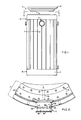
- Figure 1 is a side view of a cask for the storage and transportation of radioactive materials with the apparatus of the invention installed on the upper most portion of the wall of the cask;
- Figure 2 is a partial plan view of the walls of the cask illustrated in Figure 1 along the line 2-2;
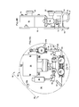
- Figure 3A is a side, cross-sectional view of the apparatus of the invention, illustrating how the housing of the apparatus is attached to an upper portion of the walls of the cask illustrated in Figure 1;
- Figure 3B is a front view of the apparatus illustrated in Figure 3A along the
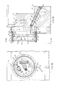
line 3B-3B, illustrating the components of the sensor assembly that are mounted on the removable inner cover of the housing; - Figure 4A is a front view of the sensor assembly that is disposed in the evacuated chamber defined in the bottom portion of the housing of the apparatus, and
- Figure 4B is a side view of the sensor assembly illustrated in Figure 4A along the line 4B-4B.
- With reference now to Figures 1 and 2, the principal purpose of the
pressure monitoring apparatus 1 of the invention is to monitor the pressure of the helium gas contained within theinterior 3 of a cask 5 used to either store or to transport radioactive materials. Such helium is typically pressurized to approximately 0.152 MPa, and serves the two-fold purpose of enhancing the expulsion of heat out of the cask 5 generated by the decay-down of the radioactive materials contained therein, and further retarding the occurrence of corrosion within thecask interior 3. Such casks 5 generally comprise acylindrical wall 7 whose lower portion 9 includes a floor plate 11 welded therearound, and whoseupper portion 13 includes astepped rim 14 for receiving alid assembly 15. Thestepped rim 14 includes a plurality of uniformly-spacedbolt holes 16 for receiving bolts (not shown) that secure thelid assembly 15 into sealing engagement with thestepped rim 14 of the cask 5. While thepressure monitoring apparatus 1 of the invention may be used in conjunction with any transportation and storage cask, the cask illustrated in this example of the invention is a peripheral-finned transportation and storage cask of the type disclosed and claimed in U.S. Patent No. 4,896,046 entitled "Fuel Rod Shipping Cask Having Peripheral Fins" issued January 23, 1990 to Larry E. Efferding and assigned to the Westinghouse Electric Corporation. - With reference now to Figures 2, 3A and 3B, the pressure monitoring apparatus includes an
annular housing 20 whose inner edge is disposed within anannular recess 22 in theupper portion 13 of thewall 7 of cask 5. Thehousing 20 includes an lowerannular member 24 whoseinner edge 25 is welded around therecess 22 to form a gas-tight seal. Thehousing 20 further includes an upper annular member 26 disposed over the outer edge of the lowerannular member 24 as shown. A removableinner cover 28 is disposed between the outer edges of the lowerannular member 24, and the inner edges of the upper annular member 26. Agasket 29 is disposed between the inner edge of theinner cover 28 and the outer edge of the lowerannular member 24, and a plurality ofbolts 30 compresses the inner edge of theinner cover 28 in gas-tight relationship with thisgasket 29. Thesebolts 30 are screwed into threadedbores 32 present around the circumference of the lowerannular member 24. - Together, the
recess 22, the lowerannular member 24 and theremovable cover 28 define an evacuatedsensor chamber 35 within thehousing 20 of thepressure monitoring apparatus 1. As will be described in more detail presently, this evacuatedsensor chamber 35 contains most of the sensor assembly 50 (illustrated in phantom 3A) of theapparatus 1, and further provides a second barrier between the pressurized helium gas disposed within theinterior 3 of the cask 5, and the ambient atmosphere. - With reference again to Figures 2, 3A and 3B, the
housing 20 further includes a removableouter cover 36 that is secured to the outer edges of the upper annular member 26 by means ofbolts 37. Together, the upper annular member 26, the removableinner cover 28, and the removableouter cover 36 define anaccess chamber 38 which contains the electrical terminals leading to thesensor assembly 50 disposed within the evacuatedsensor chamber 35, as well as a test conduit that is connected to a test port which allows a direct pressure measurement to be made of the pressure within the evacuatedsensor chamber 35. - With specific reference now to Figure 3A, the evacuated
sensor chamber 35 surrounds theouter end 40 of abore 41 that penetrates completely through thecylindrical wall 7 of the cask 5. Ashielding insert 43 is disposed within thebore 41 to prevent "streaming" of any radiation which may be emitted by radioactive materials disposed within theinterior 3 of the cask 5. The principal purpose of the shieldinginsert 43 is to definetortuous path 44 which may be easily traversed by the compressed helium within theinterior 3 of the cask 5, but which does not provide a straight path for any radiation emanating from theinterior 3 of the cask 5. Thistortuous path 44 is defined by a combination of intercommunicating radially disposed bores 45 and longitudinally disposed bores 47 as shown. While it is within the scope of the instant invention that the through-wall bore 41 might be placed in positions other than theupper portion 13 of thecylindrical wall 7 of the cask 5, theupper portion 13 is preferred due to the fact that the density of radiation emanating out of thecask interior 3 is considerably less at theupper portion 13 of the cask than it is in the middle portion, since the uppermost height of the radioactive material in the cask is always below the steppedrim 14. While such a low density of radiation is also present near the lower portion 9 of the cask 5, this location is not preferred to two reasons. First, a lower location of thehousing 20 of thepressure monitoring apparatus 1 on thecask wall 7 renders it more exposed to mechanical shock from fork lifts, etc., when the cask 5 is being handled. Secondly, if any significant amount of liquid should accumulate within thecask interior 3, these liquids might flow up through thebore 41, and damage the components of thesensor assembly 50 disposed therein. - With reference now to Figures 4A and 4B, the
sensor assembly 50 of the apparatus generally includes a mountingplate 52 having threebolt holes 54a,b,c for receiving bolts (not shown) when theassembly 50 is mounted within the evacuatedsensor chamber 35 of thehousing 20. The two key components of thesensor assembly 50 are adifferential pressure sensor 55, and anabsolute pressure sensor 56, each of which are secured (either directly or indirectly) to the mountingplate 52. In the preferred embodiment, thedifferential pressure sensor 55 is an Aschcroft@ Model No. B427S XG9 differential pressure sensor manufactured by Dresser Industries located in Milford, Connecticut, U.S.A., having a stainless steel diaphragm and a setpoint of up to 0.207 MPa (differential). Theabsolute pressure sensor 56 is preferably a model no. 211-75-700 pressure sensor having a 0.345 MPa rating of the type sold by the Paine Corporation located in Seattle, Washington, U.S.A. - A
conduit 57 connects both thedifferential pressure sensor 55 and theabsolute pressure sensor 56 in parallel to theouter end 40 of the through-wall bore 41. Theconduit 57 includes anintake tube 58 whoseupstream end 59 is brazed or welded to theouter end 40 of the through-wall bore 41, and whose downstream end is connected to two-seriallyconnected isolation valves isolation valves 60 and 62 (as well as all of theother isolation valves isolation valves differential pressure sensor 55 and theabsolute pressure sensor 56 from theouter end 40 of the through-wall bore 41 in the event that either of these two components requires replacement or maintenance. While one such isolation valve would be adequate for this purpose, two serially-connectedvalves second isolation valve 62 is connected to theinlet 63 of a T fitting 64 by way of atube elbow 66 as shown. - The
first outlet 67 of the T fitting 65 is connected to another T coupling 69 which fluidly connects thedifferential pressure sensor 55 to thegas conduit 57. For this purpose, aconduit segment 71 is disposed between thefirst outlet 67 of the T fitting 64, and the T coupling 69. On its downstream side, the T coupling 69 is connected to anelbow coupling 73 which in turn leads to theabsolute pressure sensor 56, thereby connectingabsolute pressure sensor 56 to thegas conducting conduit 57. Aconduit segment 75 interconnects the downstream side of the T coupling 69 and theelbow coupling 73 in the manner shown. - The
second outlet 77 of the T fitting 64 ultimately leads to avent plug 79 by way of aconduit segment 81.Conduit segment 81 further includes avent valve 83 which, in the preferred embodiment, is the same type of isolation valve as described with respect tovalve vent plug 79,conduit segment 81 and ventvalve 83 is to provide a controlled venting of any gas trapped between theisolation valve 62 and the differential andabsolute pressure sensors gas conducting conduit 57 disposed between theisolation valve 62 and thepressure sensors sensors respective fittings 69 and 73. - The balance of the components that form the
sensor assembly 50 are mounted on the outer surface of the removalinner cover 28, and are illustrated in Figure 3B. These components include a chamber pressure test port 85 (indicated partially in phantom) which in turn is welded or brazed in a gas-tight relationship to atesting conduit 87 that terminates in atest cap 89. Thetesting conduit 87 preferably includes anisolation valve 91 of the same type as previously described with respect to theisolation valve test port 85,testing conduit 87,test cap 89 andisolation valve 91 is to allow the system operator to make a direct measurement of the pressure of the evacuatedsensor chamber 35 for the purpose of confirming whether or not a chamber leakage signal generated by thepressure sensors chamber 35, or is merely the result of adefective sensor electrical penetration 93 which conducts the output signal-carrying cables from thepressure sensors terminal block 95 which in turn is connected to anelectrical socket assembly 97 through connectingwires 98. Theelectric socket assembly 97 receives the plug 98.5 of amonitor cable 99 as shown. Thismonitor cable 99 is connected to commercially-available read-out circuitry (not shown) which converts the electrical signals generated by the differential andabsolute pressure sensors - The final component of the
sensor assembly 50 is an auxiliary pressure sensor 100 (indicated in phantom) which is detachably connectable to thetesting conduit 87 after thetest cap 89 has been removed. The provision of the auxiliaryabsolute pressure sensor 100 allows the operator of the apparatus to make a direct measurement of the pressure within the evacuatedsensor chamber 35 when such a measurement becomes desirable. - In operation, the
differential pressure sensor 55 continuously generates an electrical signal indicative of the absolute pressure of the helium disposed within thecask interior 3, since thechamber 35 that surrounds thedifferential pressure sensor 55 is evacuated. As the helium disposed within theinterior 3 of such cask 5 is typically pressurized to about 0.152 MPa, the output of thissensor 55 will generally read 0.152 MPA. Because theabsolute pressure sensor 56 is in fact only a differential pressure sensor that uses it own, self-contained evacuated chamber as a reference point for making pressure measurements, theabsolute pressure sensor 56 should likewise continuously generate a signal indicative of a pressure reading of 0.152 MPa. However, in the event that a leakage condition should occur in either the cask 5, or in the evacuatedsensor chamber 35 that surrounds thedifferential pressure sensor 55, thesensor 55 will begin to generate a signal indicative of the presence of a lower pressure. In the preferred method of the invention, the circuitry (not shown) connected to the output of thedifferential pressure sensor 55 is programmed to generate an alarm signal when the differential pressure measured falls to about 0.122 MPa or lower. When this occurs, the operator of the apparatus immediately checks the pressure read-out generated by theabsolute pressure sensor 56. If thispressure sensor 56 likewise indicates a pressure read-out of 0.122 MPa or lower, then the system operator concludes that a leakage condition has occurred with respect to thecask 3. If, however, the pressure read-out of theabsolute pressure sensor 56 has not fallen and is still substantially at a level of approximately 0.152 MPa, then the operator of the apparatus tentatively concludes that a leakage condition has occurred with respect to the evacuatedsensor chamber 35. - In the next step of the method of the invention, the operator of the apparatus confirms whether or not a leakage condition has occurred with respect to the evacuated
sensor chamber 35 by removing theouter cover 36, and thetest cap 89, and connecting theauxiliary pressure sensor 100 to thetesting conduit 87. Once this has been accomplished, theisolation valve 91 is opened. If the resulting pressure reading is 0.030 MPa or higher, then the system operator concludes that a leakage condition with respect to the evacuatedsensor chamber 35 has, indeed, occurred. If on the other hand theauxiliary pressure sensor 100 indicates that the evacuatedsensor chamber 35 is still substantially evacuated, then the operator of theapparatus 1 concludes that the output of thedifferential pressure sensor 55 is in error, either as the result of drift in its set point, or some other type of mechanical failure. In either case, the operator of theapparatus 1 proceeds to either repair or replace thedifferential pressure sensor 55 by first removing removableinner cover 28, and then closing theisolation valves conduit 57 by removing thevent plug 79, connecting a suction hose to the vent port, and then opening thevent valve 83. After the venting operation has been accomplished, not only is thedifferential pressure sensor 55 removed and repaired, but theabsolute pressure sensor 56 is tested to make sure that the read-out generated thereby is accurate and correct. After the foregoing maintenance operations have been accomplished, theapparatus 1 is reassembled, and placed back into operation.
Claims (12)
Applications Claiming Priority (2)
| Application Number | Priority Date | Filing Date | Title |
|---|---|---|---|
| US07/558,996 US5089214A (en) | 1990-07-26 | 1990-07-26 | Apparatus for monitoring the pressure within a cask containing radioactive material |
| US558996 | 1990-07-26 |
Publications (2)
| Publication Number | Publication Date |
|---|---|
| EP0468233A2 true EP0468233A2 (en) | 1992-01-29 |
| EP0468233A3 EP0468233A3 (en) | 1992-11-04 |
Family
ID=24231860
Family Applications (1)
| Application Number | Title | Priority Date | Filing Date |
|---|---|---|---|
| EP19910110967 Ceased EP0468233A3 (en) | 1990-07-26 | 1991-07-02 | Apparatus and method for monitoring the pressure within a cask containing potentially hazardous gas |
Country Status (5)
| Country | Link |
|---|---|
| US (1) | US5089214A (en) |
| EP (1) | EP0468233A3 (en) |
| JP (1) | JPH0795114B2 (en) |
| KR (1) | KR920003332A (en) |
| CN (1) | CN1058484A (en) |
Cited By (1)
| Publication number | Priority date | Publication date | Assignee | Title |
|---|---|---|---|---|
| WO1998004912A1 (en) * | 1996-07-24 | 1998-02-05 | Siemens Aktiengesellschaft | Gas analyser for explosion hazard areas |
Families Citing this family (11)
| Publication number | Priority date | Publication date | Assignee | Title |
|---|---|---|---|---|
| US5680109A (en) * | 1996-06-21 | 1997-10-21 | The Foxboro Company | Impulse line blockage detector systems and methods |
| FR2777090B1 (en) * | 1998-04-07 | 2000-05-05 | Commissariat Energie Atomique | METHOD OF MEASURING THE TRITIUM ACTIVITY OF A RADIOACTIVE WASTE DRUM |
| US20080137794A1 (en) * | 2005-12-01 | 2008-06-12 | Nac International, Inc. | Systems and methods for loading and transferring spent nuclear fuel |
| DE102008011686A1 (en) * | 2008-02-28 | 2009-09-03 | Inficon Gmbh | helium sensor |
| CN101881687A (en) * | 2010-05-28 | 2010-11-10 | 上海宏力半导体制造有限公司 | Leak detection device of semiconductor manufacturing platform as well as use method and platform thereof |
| CN105264352A (en) * | 2013-06-06 | 2016-01-20 | Abb技术有限公司 | Method and device for determining an average parameter of a fluid in a closable container |
| JP2017078671A (en) * | 2015-10-22 | 2017-04-27 | 日立Geニュークリア・エナジー株式会社 | Radiation shield box and radiation shield box assembly set |
| CN106482451B (en) * | 2016-09-23 | 2022-05-27 | 广东核电合营有限公司 | Vacuum drying and helium filling device for spent fuel storage and transportation container |
| RU2697656C1 (en) * | 2018-12-28 | 2019-08-16 | Акционерное общество "Федеральный центр ядерной и радиационной безопасности" (АО ФЦЯРБ) | Method for long-term dry storage of spent nuclear fuel and container for its implementation |
| DE102019133816A1 (en) * | 2019-12-10 | 2021-06-10 | Endress+Hauser SE+Co. KG | Pressure sensor for determining a relative pressure variable |
| CN112857696A (en) * | 2021-02-02 | 2021-05-28 | 原子高科股份有限公司 | Leakage detection device and detection method for radioactive gas sealed container |
Citations (11)
| Publication number | Priority date | Publication date | Assignee | Title |
|---|---|---|---|---|
| US3817283A (en) * | 1971-04-07 | 1974-06-18 | J Hewson | Differential pressure transducer process mounting support |
| JPS51135579A (en) * | 1975-05-20 | 1976-11-24 | Rikagaku Kenkyusho | Pressure detector |
| US4126034A (en) * | 1978-01-30 | 1978-11-21 | Rheem Manufacturing Company | Method and apparatus for container pressure testing |
| EP0031048A1 (en) * | 1979-12-13 | 1981-07-01 | Kraftwerk Union Aktiengesellschaft | Device and method for storing spent fuel elements |
| GB2069703A (en) * | 1980-02-13 | 1981-08-26 | Honeywell Inc | Overload protection of differential pressure transducers |
| US4299129A (en) * | 1978-06-16 | 1981-11-10 | Klaus Ritzinger | Pressure measuring device |
| DD152629A1 (en) * | 1980-08-15 | 1981-12-02 | Neitherd Rosahl | DEVICE AND METHOD FOR THE LEAKAGE TESTING OF CERTAIN PLANTS AND ITS SYSTEMS |
| JPS5857501A (en) * | 1981-09-29 | 1983-04-05 | Toshiba Corp | Absolute pressure transducer |
| GB2148506A (en) * | 1983-10-19 | 1985-05-30 | Illinois Tool Works | Vacuum or pressure differential alarm device |
| US4888992A (en) * | 1988-04-15 | 1989-12-26 | Honeywell Inc. | Absolute pressure transducer and method for making same |
| US4983352A (en) * | 1984-11-13 | 1991-01-08 | Westinghouse Electric Corp. | Closure system for a spent fuel storage cask |
Family Cites Families (9)
| Publication number | Priority date | Publication date | Assignee | Title |
|---|---|---|---|---|
| US3100986A (en) * | 1960-07-08 | 1963-08-20 | Starr Kap Engineering Company | Leakage indicator |
| US3982134A (en) * | 1974-03-01 | 1976-09-21 | Housholder William R | Shipping container for nuclear fuels |
| DE7737499U1 (en) * | 1977-12-09 | 1978-05-24 | Steag Kernenergie Gmbh, 4300 Essen | SHIELD TRANSPORT AND / OR SHIELD STORAGE CONTAINER FOR RADIOACTIVE WASTE |
| DE3010518A1 (en) * | 1980-03-19 | 1981-10-01 | GNS Gesellschaft für Nuklear-Service mbH, 4300 Essen | COMPONENT KIT FOR SHIELDED TRANSPORT AND FOR SHIELDED STORAGE OF RADIOACTIVE SUBSTANCES |
| DE3025795C2 (en) * | 1980-07-08 | 1986-08-28 | GNS Gesellschaft für Nuklear-Service mbH, 4300 Essen | Process for the continuous monitoring of two sealing barriers in shielding transport and storage containers for radioactive substances |
| DE3037290C2 (en) * | 1980-10-02 | 1983-01-20 | Transnuklear Gmbh, 6450 Hanau | Transport and / or storage containers for radioactive substances |
| DE3127219A1 (en) * | 1981-07-10 | 1983-01-27 | GNS Gesellschaft für Nuklear-Service mbH, 4300 Essen | SHIELDING TRANSPORT AND / OR SHIELDING CONTAINER |
| IT1185498B (en) * | 1984-11-13 | 1987-11-12 | Westinghouse Electric Corp | CLOSING SYSTEM OF A DRUM FOR THE STORAGE OF OUT OF FUEL |
| JPH01131200U (en) * | 1988-03-01 | 1989-09-06 |
-
1990
- 1990-07-26 US US07/558,996 patent/US5089214A/en not_active Expired - Fee Related
-
1991
- 1991-07-02 EP EP19910110967 patent/EP0468233A3/en not_active Ceased
- 1991-07-24 KR KR1019910012710A patent/KR920003332A/en not_active Application Discontinuation
- 1991-07-25 CN CN91105049A patent/CN1058484A/en active Pending
- 1991-07-26 JP JP3209833A patent/JPH0795114B2/en not_active Expired - Lifetime
Patent Citations (11)
| Publication number | Priority date | Publication date | Assignee | Title |
|---|---|---|---|---|
| US3817283A (en) * | 1971-04-07 | 1974-06-18 | J Hewson | Differential pressure transducer process mounting support |
| JPS51135579A (en) * | 1975-05-20 | 1976-11-24 | Rikagaku Kenkyusho | Pressure detector |
| US4126034A (en) * | 1978-01-30 | 1978-11-21 | Rheem Manufacturing Company | Method and apparatus for container pressure testing |
| US4299129A (en) * | 1978-06-16 | 1981-11-10 | Klaus Ritzinger | Pressure measuring device |
| EP0031048A1 (en) * | 1979-12-13 | 1981-07-01 | Kraftwerk Union Aktiengesellschaft | Device and method for storing spent fuel elements |
| GB2069703A (en) * | 1980-02-13 | 1981-08-26 | Honeywell Inc | Overload protection of differential pressure transducers |
| DD152629A1 (en) * | 1980-08-15 | 1981-12-02 | Neitherd Rosahl | DEVICE AND METHOD FOR THE LEAKAGE TESTING OF CERTAIN PLANTS AND ITS SYSTEMS |
| JPS5857501A (en) * | 1981-09-29 | 1983-04-05 | Toshiba Corp | Absolute pressure transducer |
| GB2148506A (en) * | 1983-10-19 | 1985-05-30 | Illinois Tool Works | Vacuum or pressure differential alarm device |
| US4983352A (en) * | 1984-11-13 | 1991-01-08 | Westinghouse Electric Corp. | Closure system for a spent fuel storage cask |
| US4888992A (en) * | 1988-04-15 | 1989-12-26 | Honeywell Inc. | Absolute pressure transducer and method for making same |
Non-Patent Citations (2)
| Title |
|---|
| PATENT ABSTRACTS OF JAPAN vol. 1, no. 38 (E-2256)(76) 19 April 1977 & JP-A-51 135 579 ( RIKAGAKU KENKYU JO ) 24 November 1976 * |
| PATENT ABSTRACTS OF JAPAN vol. 7, no. 145 (M-224)(1290) 24 June 1983 & JP-A-58 057 501 ( TOKYO SHIBAURA DENKI K.K. ) 5 April 1983 * |
Cited By (1)
| Publication number | Priority date | Publication date | Assignee | Title |
|---|---|---|---|---|
| WO1998004912A1 (en) * | 1996-07-24 | 1998-02-05 | Siemens Aktiengesellschaft | Gas analyser for explosion hazard areas |
Also Published As
| Publication number | Publication date |
|---|---|
| KR920003332A (en) | 1992-02-29 |
| EP0468233A3 (en) | 1992-11-04 |
| US5089214A (en) | 1992-02-18 |
| JPH0795114B2 (en) | 1995-10-11 |
| CN1058484A (en) | 1992-02-05 |
| JPH04250398A (en) | 1992-09-07 |
Similar Documents
| Publication | Publication Date | Title |
|---|---|---|
| US6223587B1 (en) | Device and method for permanently controlling the tightness of closing lids of containers for radioactive materials | |
| US5182076A (en) | Method for monitoring the emplacement of a transportable element and the tightness of its joint with a fixed structure, and the use of this method | |
| EP0468233A2 (en) | Cask for storage or transport of radioactive materials | |
| KR100704214B1 (en) | Monitoring of ultra-high purity product storage tanks during transportation | |
| EP0321295A2 (en) | Automatic pump protection system | |
| US6114710A (en) | Transport packing for dangerous packages such as high activity nuclear packages | |
| EP0580524A1 (en) | Seal leakage monitoring device and method | |
| EP3754235A1 (en) | A method and device for in-situ testing a vacuum-pressure valve of a storage tank | |
| US4427893A (en) | Apparatus and method for storing spent fuel assemblies | |
| EP1590814B1 (en) | Method for shipping uranium hexafluoride | |
| JP2000258595A (en) | Monitor for double lid of canister | |
| US11326929B2 (en) | Separated solids monitoring system | |
| JP7292880B2 (en) | Nuclear hot isostatic pressing | |
| JPS6020027Y2 (en) | Leak detection device for nuclear fuel rod sealed cans | |
| US11605474B2 (en) | Container and method for storing spent nuclear fuel | |
| CZ2000193A3 (en) | Process and apparatus for continuous check of tightness of closing covers of containers for radioactive materials | |
| CN210720253U (en) | Probe detection device | |
| HANFORD et al. | 2.6 PRE-OPERATIONAL TESTING AND INSPECTION | |
| SU1751087A1 (en) | Hermetically sealed container for cylinders with toxic matter | |
| Legeay | Handling of UF/sub 6/in US gaseous diffusion plants | |
| Hayes | PRTR CONTAINMENT VESSEL LEAK RATE TEST EXPERIENCE. | |
| Spilker et al. | Castor V/HAWC Transport Cask for High Active Liquid Waste | |
| Pierce | Multi-canister overpack operations and maintenance manual | |
| Umek et al. | FFTF in-containment cell liner design and installation experience | |
| Slavov et al. | Detection of primary coolant leaks in NPP |
Legal Events
| Date | Code | Title | Description |
|---|---|---|---|
| PUAI | Public reference made under article 153(3) epc to a published international application that has entered the european phase |
Free format text: ORIGINAL CODE: 0009012 |
|
| AK | Designated contracting states |
Kind code of ref document: A2 Designated state(s): BE CH ES FR GB IT LI |
|
| PUAL | Search report despatched |
Free format text: ORIGINAL CODE: 0009013 |
|
| AK | Designated contracting states |
Kind code of ref document: A3 Designated state(s): BE CH ES FR GB IT LI |
|
| 17P | Request for examination filed |
Effective date: 19921222 |
|
| 17Q | First examination report despatched |
Effective date: 19940322 |
|
| STAA | Information on the status of an ep patent application or granted ep patent |
Free format text: STATUS: THE APPLICATION HAS BEEN REFUSED |
|
| 18R | Application refused |
Effective date: 19950821 |