EP0469444B1 - Method and apparatus for disparsing biochemical reagents onto a target in precisely controlled volumes - Google Patents
Method and apparatus for disparsing biochemical reagents onto a target in precisely controlled volumes Download PDFInfo
- Publication number
- EP0469444B1 EP0469444B1 EP91112388A EP91112388A EP0469444B1 EP 0469444 B1 EP0469444 B1 EP 0469444B1 EP 91112388 A EP91112388 A EP 91112388A EP 91112388 A EP91112388 A EP 91112388A EP 0469444 B1 EP0469444 B1 EP 0469444B1
- Authority
- EP
- European Patent Office
- Prior art keywords
- liquid
- reagent
- jet
- target
- analysis
- Prior art date
- Legal status (The legal status is an assumption and is not a legal conclusion. Google has not performed a legal analysis and makes no representation as to the accuracy of the status listed.)
- Expired - Lifetime
Links
Images


Classifications
-
- G—PHYSICS
- G01—MEASURING; TESTING
- G01N—INVESTIGATING OR ANALYSING MATERIALS BY DETERMINING THEIR CHEMICAL OR PHYSICAL PROPERTIES
- G01N33/00—Investigating or analysing materials by specific methods not covered by groups G01N1/00 - G01N31/00
- G01N33/48—Biological material, e.g. blood, urine; Haemocytometers
- G01N33/50—Chemical analysis of biological material, e.g. blood, urine; Testing involving biospecific ligand binding methods; Immunological testing
-
- B—PERFORMING OPERATIONS; TRANSPORTING
- B01—PHYSICAL OR CHEMICAL PROCESSES OR APPARATUS IN GENERAL
- B01L—CHEMICAL OR PHYSICAL LABORATORY APPARATUS FOR GENERAL USE
- B01L3/00—Containers or dishes for laboratory use, e.g. laboratory glassware; Droppers
- B01L3/02—Burettes; Pipettes
- B01L3/0241—Drop counters; Drop formers
- B01L3/0268—Drop counters; Drop formers using pulse dispensing or spraying, eg. inkjet type, piezo actuated ejection of droplets from capillaries
-
- B—PERFORMING OPERATIONS; TRANSPORTING
- B82—NANOTECHNOLOGY
- B82Y—SPECIFIC USES OR APPLICATIONS OF NANOSTRUCTURES; MEASUREMENT OR ANALYSIS OF NANOSTRUCTURES; MANUFACTURE OR TREATMENT OF NANOSTRUCTURES
- B82Y30/00—Nanotechnology for materials or surface science, e.g. nanocomposites
-
- G—PHYSICS
- G01—MEASURING; TESTING
- G01N—INVESTIGATING OR ANALYSING MATERIALS BY DETERMINING THEIR CHEMICAL OR PHYSICAL PROPERTIES
- G01N35/00—Automatic analysis not limited to methods or materials provided for in any single one of groups G01N1/00 - G01N33/00; Handling materials therefor
- G01N35/10—Devices for transferring samples or any liquids to, in, or from, the analysis apparatus, e.g. suction devices, injection devices
- G01N35/1002—Reagent dispensers
-
- B—PERFORMING OPERATIONS; TRANSPORTING
- B01—PHYSICAL OR CHEMICAL PROCESSES OR APPARATUS IN GENERAL
- B01J—CHEMICAL OR PHYSICAL PROCESSES, e.g. CATALYSIS OR COLLOID CHEMISTRY; THEIR RELEVANT APPARATUS
- B01J2219/00—Chemical, physical or physico-chemical processes in general; Their relevant apparatus
- B01J2219/00274—Sequential or parallel reactions; Apparatus and devices for combinatorial chemistry or for making arrays; Chemical library technology
- B01J2219/00277—Apparatus
- B01J2219/00351—Means for dispensing and evacuation of reagents
- B01J2219/00378—Piezo-electric or ink jet dispensers
-
- B—PERFORMING OPERATIONS; TRANSPORTING
- B01—PHYSICAL OR CHEMICAL PROCESSES OR APPARATUS IN GENERAL
- B01J—CHEMICAL OR PHYSICAL PROCESSES, e.g. CATALYSIS OR COLLOID CHEMISTRY; THEIR RELEVANT APPARATUS
- B01J2219/00—Chemical, physical or physico-chemical processes in general; Their relevant apparatus
- B01J2219/00274—Sequential or parallel reactions; Apparatus and devices for combinatorial chemistry or for making arrays; Chemical library technology
- B01J2219/00277—Apparatus
- B01J2219/00497—Features relating to the solid phase supports
- B01J2219/00527—Sheets
-
- B—PERFORMING OPERATIONS; TRANSPORTING
- B01—PHYSICAL OR CHEMICAL PROCESSES OR APPARATUS IN GENERAL
- B01J—CHEMICAL OR PHYSICAL PROCESSES, e.g. CATALYSIS OR COLLOID CHEMISTRY; THEIR RELEVANT APPARATUS
- B01J2219/00—Chemical, physical or physico-chemical processes in general; Their relevant apparatus
- B01J2219/00274—Sequential or parallel reactions; Apparatus and devices for combinatorial chemistry or for making arrays; Chemical library technology
- B01J2219/00583—Features relative to the processes being carried out
- B01J2219/00603—Making arrays on substantially continuous surfaces
- B01J2219/00605—Making arrays on substantially continuous surfaces the compounds being directly bound or immobilised to solid supports
- B01J2219/0061—The surface being organic
-
- B—PERFORMING OPERATIONS; TRANSPORTING
- B01—PHYSICAL OR CHEMICAL PROCESSES OR APPARATUS IN GENERAL
- B01J—CHEMICAL OR PHYSICAL PROCESSES, e.g. CATALYSIS OR COLLOID CHEMISTRY; THEIR RELEVANT APPARATUS
- B01J2219/00—Chemical, physical or physico-chemical processes in general; Their relevant apparatus
- B01J2219/00274—Sequential or parallel reactions; Apparatus and devices for combinatorial chemistry or for making arrays; Chemical library technology
- B01J2219/00583—Features relative to the processes being carried out
- B01J2219/00603—Making arrays on substantially continuous surfaces
- B01J2219/00605—Making arrays on substantially continuous surfaces the compounds being directly bound or immobilised to solid supports
- B01J2219/00623—Immobilisation or binding
- B01J2219/0063—Other, e.g. van der Waals forces, hydrogen bonding
-
- B—PERFORMING OPERATIONS; TRANSPORTING
- B01—PHYSICAL OR CHEMICAL PROCESSES OR APPARATUS IN GENERAL
- B01J—CHEMICAL OR PHYSICAL PROCESSES, e.g. CATALYSIS OR COLLOID CHEMISTRY; THEIR RELEVANT APPARATUS
- B01J2219/00—Chemical, physical or physico-chemical processes in general; Their relevant apparatus
- B01J2219/00274—Sequential or parallel reactions; Apparatus and devices for combinatorial chemistry or for making arrays; Chemical library technology
- B01J2219/00583—Features relative to the processes being carried out
- B01J2219/00603—Making arrays on substantially continuous surfaces
- B01J2219/00605—Making arrays on substantially continuous surfaces the compounds being directly bound or immobilised to solid supports
- B01J2219/00632—Introduction of reactive groups to the surface
- B01J2219/00637—Introduction of reactive groups to the surface by coating it with another layer
-
- B—PERFORMING OPERATIONS; TRANSPORTING
- B01—PHYSICAL OR CHEMICAL PROCESSES OR APPARATUS IN GENERAL
- B01J—CHEMICAL OR PHYSICAL PROCESSES, e.g. CATALYSIS OR COLLOID CHEMISTRY; THEIR RELEVANT APPARATUS
- B01J2219/00—Chemical, physical or physico-chemical processes in general; Their relevant apparatus
- B01J2219/00274—Sequential or parallel reactions; Apparatus and devices for combinatorial chemistry or for making arrays; Chemical library technology
- B01J2219/00583—Features relative to the processes being carried out
- B01J2219/00603—Making arrays on substantially continuous surfaces
- B01J2219/00639—Making arrays on substantially continuous surfaces the compounds being trapped in or bound to a porous medium
- B01J2219/00641—Making arrays on substantially continuous surfaces the compounds being trapped in or bound to a porous medium the porous medium being continuous, e.g. porous oxide substrates
-
- B—PERFORMING OPERATIONS; TRANSPORTING
- B01—PHYSICAL OR CHEMICAL PROCESSES OR APPARATUS IN GENERAL
- B01J—CHEMICAL OR PHYSICAL PROCESSES, e.g. CATALYSIS OR COLLOID CHEMISTRY; THEIR RELEVANT APPARATUS
- B01J2219/00—Chemical, physical or physico-chemical processes in general; Their relevant apparatus
- B01J2219/00274—Sequential or parallel reactions; Apparatus and devices for combinatorial chemistry or for making arrays; Chemical library technology
- B01J2219/00583—Features relative to the processes being carried out
- B01J2219/00603—Making arrays on substantially continuous surfaces
- B01J2219/00659—Two-dimensional arrays
-
- B—PERFORMING OPERATIONS; TRANSPORTING
- B01—PHYSICAL OR CHEMICAL PROCESSES OR APPARATUS IN GENERAL
- B01J—CHEMICAL OR PHYSICAL PROCESSES, e.g. CATALYSIS OR COLLOID CHEMISTRY; THEIR RELEVANT APPARATUS
- B01J2219/00—Chemical, physical or physico-chemical processes in general; Their relevant apparatus
- B01J2219/00274—Sequential or parallel reactions; Apparatus and devices for combinatorial chemistry or for making arrays; Chemical library technology
- B01J2219/00583—Features relative to the processes being carried out
- B01J2219/00603—Making arrays on substantially continuous surfaces
- B01J2219/00677—Ex-situ synthesis followed by deposition on the substrate
-
- C—CHEMISTRY; METALLURGY
- C40—COMBINATORIAL TECHNOLOGY
- C40B—COMBINATORIAL CHEMISTRY; LIBRARIES, e.g. CHEMICAL LIBRARIES
- C40B60/00—Apparatus specially adapted for use in combinatorial chemistry or with libraries
- C40B60/14—Apparatus specially adapted for use in combinatorial chemistry or with libraries for creating libraries
-
- G—PHYSICS
- G01—MEASURING; TESTING
- G01N—INVESTIGATING OR ANALYSING MATERIALS BY DETERMINING THEIR CHEMICAL OR PHYSICAL PROPERTIES
- G01N35/00—Automatic analysis not limited to methods or materials provided for in any single one of groups G01N1/00 - G01N33/00; Handling materials therefor
- G01N35/10—Devices for transferring samples or any liquids to, in, or from, the analysis apparatus, e.g. suction devices, injection devices
- G01N2035/1027—General features of the devices
- G01N2035/1034—Transferring microquantities of liquid
- G01N2035/1041—Ink-jet like dispensers
-
- G—PHYSICS
- G01—MEASURING; TESTING
- G01N—INVESTIGATING OR ANALYSING MATERIALS BY DETERMINING THEIR CHEMICAL OR PHYSICAL PROPERTIES
- G01N35/00—Automatic analysis not limited to methods or materials provided for in any single one of groups G01N1/00 - G01N33/00; Handling materials therefor
- G01N35/00009—Automatic analysis not limited to methods or materials provided for in any single one of groups G01N1/00 - G01N33/00; Handling materials therefor provided with a sample supporting tape, e.g. with absorbent zones
-
- G—PHYSICS
- G01—MEASURING; TESTING
- G01N—INVESTIGATING OR ANALYSING MATERIALS BY DETERMINING THEIR CHEMICAL OR PHYSICAL PROPERTIES
- G01N35/00—Automatic analysis not limited to methods or materials provided for in any single one of groups G01N1/00 - G01N33/00; Handling materials therefor
- G01N35/0099—Automatic analysis not limited to methods or materials provided for in any single one of groups G01N1/00 - G01N33/00; Handling materials therefor comprising robots or similar manipulators
-
- Y—GENERAL TAGGING OF NEW TECHNOLOGICAL DEVELOPMENTS; GENERAL TAGGING OF CROSS-SECTIONAL TECHNOLOGIES SPANNING OVER SEVERAL SECTIONS OF THE IPC; TECHNICAL SUBJECTS COVERED BY FORMER USPC CROSS-REFERENCE ART COLLECTIONS [XRACs] AND DIGESTS
- Y10—TECHNICAL SUBJECTS COVERED BY FORMER USPC
- Y10T—TECHNICAL SUBJECTS COVERED BY FORMER US CLASSIFICATION
- Y10T436/00—Chemistry: analytical and immunological testing
- Y10T436/11—Automated chemical analysis
- Y10T436/110833—Utilizing a moving indicator strip or tape
-
- Y—GENERAL TAGGING OF NEW TECHNOLOGICAL DEVELOPMENTS; GENERAL TAGGING OF CROSS-SECTIONAL TECHNOLOGIES SPANNING OVER SEVERAL SECTIONS OF THE IPC; TECHNICAL SUBJECTS COVERED BY FORMER USPC CROSS-REFERENCE ART COLLECTIONS [XRACs] AND DIGESTS
- Y10—TECHNICAL SUBJECTS COVERED BY FORMER USPC
- Y10T—TECHNICAL SUBJECTS COVERED BY FORMER US CLASSIFICATION
- Y10T436/00—Chemistry: analytical and immunological testing
- Y10T436/11—Automated chemical analysis
- Y10T436/112499—Automated chemical analysis with sample on test slide
-
- Y—GENERAL TAGGING OF NEW TECHNOLOGICAL DEVELOPMENTS; GENERAL TAGGING OF CROSS-SECTIONAL TECHNOLOGIES SPANNING OVER SEVERAL SECTIONS OF THE IPC; TECHNICAL SUBJECTS COVERED BY FORMER USPC CROSS-REFERENCE ART COLLECTIONS [XRACs] AND DIGESTS
- Y10—TECHNICAL SUBJECTS COVERED BY FORMER USPC
- Y10T—TECHNICAL SUBJECTS COVERED BY FORMER US CLASSIFICATION
- Y10T436/00—Chemistry: analytical and immunological testing
- Y10T436/25—Chemistry: analytical and immunological testing including sample preparation
- Y10T436/2575—Volumetric liquid transfer
Definitions
- the invention relates to a method for the metered supply of an analysis liquid containing biochemical macromolecules to a target, in which this liquid is ejected in small quanta in bursts through a nozzle onto the target, and a corresponding device.
- the liquid can be, for example, a sample liquid, in particular blood or serum, a reagent liquid or a calibration liquid.
- a sample liquid in particular blood or serum
- a reagent liquid or a calibration liquid.
- these liquids contain proteins or other macromolecules involved in biochemical processes.
- the target to which the liquid is to be supplied can be a reaction vessel, in automated analyzers today very small plastic reaction vessels are predominantly used.
- Another example is the microtiter plates that are widely used in microbiology.
- a particularly important case for the invention is the application of the analysis liquid to an analysis element (often also referred to as a "test carrier” and in the Anglo-Saxon literature as a "solid state analysis element").
- this term encompasses both discrete analysis elements and also tapes, strips or other forms of continuous analysis elements which can be continuously passed past a metering station to which the analysis liquid is applied.
- EP-A-119 573 and EP-A-268 237 deal with methods and devices of the type described in the introduction. Their technology is based on the ink jet originally developed for computer printers (ink jet printers) -Technology. Both documents contain more detailed explanations of the prior art to which reference is made here.
- EP-A-119 573 is particularly concerned with the problem of providing an inexpensive "pump element" which is designed as a disposable (single-use) component.
- the nozzle chamber is essentially formed by a section of an elastic hose, which is part of the pump element.
- An electromagnetically moved cylinder rod is directed against its side surface, which is moved against the hose when a drop is to be ejected.
- EP-A-268 237 describes a device in which the nozzle chamber consists of a tube piece which is enclosed by a coaxial, likewise tubular piezoelectric actuating element and is compressed when a drop is to be ejected.
- the invention is based on the object of providing a method or a device for applying microquants of biochemical analysis liquids which is structurally less complex in comparison to the previously known methods and a highly precise metering of very small quanta (less than 1 ⁇ l) with a high frequency (more than 1000 Hz).
- the object is achieved in a method of the type mentioned in the introduction in that a partial volume of the liquid in the nozzle chamber is briefly evaporated and expanded in order to expel a quantity of the liquid through the nozzle.
- the technology on which the method according to the invention is based is known from computer printers. It is referred to there as the "bubble jet technique" and is known, for example, from US Pat. No. 4,376,945. As part of the The present invention has surprisingly found that this printing technique can be applied to the application of analysis liquids.
- the solution according to the present invention is characterized in particular by the fact that no mechanically moving parts are required. This leads to increased reliability. In addition, very small liquid quanta with a comparatively high frequency can be produced.
- reagent liquids can be applied as a predetermined pattern of compartments to the reagent area 1 of an analysis element 2.
- the term "compartment” here means a delimited sub-area.
- a nozzle head generally designated 3, with a nozzle chamber 4 and a nozzle 5.
- a heating element 7 which is in thermal contact with the analysis liquid 6 contained in the nozzle chamber 4.
- a control unit 8 Controlled by a control unit 8, a current pulse is applied to the heating element 7 via a pulse generator 9 and an amplifier 10 when a quantity of analysis liquid 6 is to be ejected from the nozzle 5.
- a vapor bubble 11 forms very quickly (within about 200 microseconds).
- nozzle unit As it expands, a liquid drop is expelled from the nozzle 5.
- the nozzle chamber 4 is connected via a line 12 with filter 13 to a reservoir 14 for analysis liquid 6.
- Nozzle head 3, filter 13 and storage container 14 can be accommodated in a disposable cartridge (“nozzle unit”).
- the analysis element 2 can be positioned with the help of an X-Y drive 15, which is also controlled by the control unit 8, and a positioning table 16 in both surface directions of the reagent area 1 in such a way that reagent liquid quanta ejected in succession from the nozzle 5 form a predetermined pattern.
- the nozzle head 3 can also be moved accordingly.
- the nozzle heads 3 with only one heating element 7 and one nozzle 5.
- the nozzle heads with a plurality of nozzles (usually 9, 12 or 24 nozzles) which are customary for ink jet printing processes can be used.
- the required movement of the analysis element 2 when generating a predetermined pattern can be reduced and the metering output can be increased.
- the pulse generator 9 and the amplifier 10 are of course designed to be multi-channel.
- the structural elements known for bubble jet technology can be used in the invention. It is therefore not necessary to go into structural details of the device, in particular the nozzle chamber, the nozzle or the heating elements. This information can be found in the literature on bubble jet inkjet printers.
- a particular advantage of the invention is that it is possible to produce a nozzle unit so inexpensively that it can be designed as a disposable element which contains a supply of analysis liquid ready for use (prepacked by the manufacturer). This eliminates the need for time-consuming steps when carrying out analyzes with the appropriate devices. This makes it possible to provide extremely versatile and easy-to-use analysis systems (consisting of a device and specifically tailored reagents) with relatively little design effort. Such a system is shown by way of example in FIG. 2.
- a tape 20 is used as the analysis element, which consists of a suitable reagent carrier material, for example paper or a plastic film. It is gradually transported from an initial roller 21 to an end roller 22.
- a reagent metering station 23 Arranged above the belt 20 in a reagent metering station 23 are a plurality of holders 24 on the device side, which cooperate with holder elements 27 on the nozzle units 25 in order to position them interchangeably at defined positions above the belt 20.
- Electrical contacts 24a, 25a are provided on the brackets 24 and on the nozzle units 25, which enable an electrical connection between the device and a nozzle unit inserted into a holder 24.
- a sample metering unit 28 In the transport direction of the belt 20 (arrow 26) behind the reagent metering station 23 there are further processing units, in the case shown a sample metering unit 28, two washing units 29a, 29b, another reagent metering station 31 and a measuring unit 30.
- the analysis method begins with analysis liquids, in particular reagents, being applied to the belt 20 through one or more of the nozzle units 25 of the reagent metering station 23, which form reagent areas 32 on the belt.
- the nozzle units 25 have a plurality of nozzles arranged side by side in their nozzle head 3. Alternatively or additionally, they can be movable transversely to the transport direction 26 of the belt 20 with a mechanism (not shown).
- a sample is added by the sample metering unit 28.
- the washing units 29a and 29b allow washing steps to be carried out if necessary.
- the reagent metering station 31 permits the metering of a further reagent.
- the measuring unit 30 is used to measure a physical measurement variable which is characteristic of the analysis, for example the optical reflection or fluorescence at a specific measurement wavelength.
- the invention can be used in a large number of different methods (for example homogeneous and heterogeneous immunoassays, enzymatic determinations, etc.) in which an analysis element, after the supply of the reagent liquid, is transported in a continuous process to a sample addition station, a sample is contacted with the reaction surface and an in As a result of the reaction of the sample and the reagent, a physically measurable change is measured.
- This procedure has been proposed earlier, in particular in US-A-3,526,480, to which reference is made here.
- the device can be converted to different analyzes that work with different reagents by simply replacing the nozzle units 25, without having to replace the reagent containers and without having to rinse the supply hoses and dosing systems that are usually used.
- the arrangement of several nozzle element holders along the transport path of an analysis element transported step by step in a continuous process makes it possible, on the one hand, to dose several different reagents at different times and, on the other hand, the time that elapses between the application on the analysis element and the sample addition, in easily adapt to the respective requirements.
- the continuously transported analysis element does not necessarily have to be designed in the form of a band.
- small reaction vessels for example in the form of interlinked flat plastic shells or other continuously transportable reagent carriers, could also be used.
- the invention can advantageously be used for the application of a wide variety of reagents customary in clinical chemistry on a solid support.
- enzymes, substrates or other soluble reaction components can be applied to the support in such a way that they are easy to elute in order to react in the liquid phase.
- the invention can also be used advantageously for the application of carrier-fixed reagents (in particular antibodies, antigens, etc.).
- carrier-fixed reagents in particular antibodies, antigens, etc.
- a large area of a support material can be provided with a surface coating containing streptavidin, to which selectively and selectively biotinylated reagents are applied, which are bound to the support via the biotin-streptavidin bond. Further details are described in EP0 469 445 A1, to which reference is made here.
- the quanta of different reagent liquids preferably form a pattern of alternating compartments, where they are close to one another but spatially separated.
- FIG. 3 Such a compartment pattern is shown in FIG. 3.
- the quanta of the reagent liquid form a plurality of row-shaped compartments 35, which each consist of many closely spaced surface elements (“dots”) 36, each of which is generated by a quantum of the reagent liquid.
- the carrier is charged with the reagent liquid in a continuous process, as shown in FIG. 2, the different compartments of the same reagent composition can expediently be expelled from different nozzles of the same nozzle unit 25.
- the transport direction runs parallel to the rows (arrow 26).
- the letters given at the top of FIG. 3 designate three different sets A, B, C, of compartments 35, the compartments 35 of the same set containing the same reagents, while the reagents of different sets differ in their chemical composition.
- the dots within the compartments have a center distance of little more than 0.1 mm.
- the center distance of the compartments from each other is approx. 0.26 mm.
- every second was used. In principle, an even closer spacing of the surface elements is possible.
- the ink of a bubble jet print head (Hewlett-Packard type Quiet Jet plus) is exchanged for a tartrazine dye solution.
- This print head is housed together with an ink reservoir in a removable cartridge.
- the print head is controlled by a personal computer using a basic control program.
- each tube contained 2 ml of ABTS R substrate solution (1.9 mmol / l 2,2'-azino-di- [3-ethyl-benzothiazoline-sulfonic acid (6)) diammonium salt; 100 mmol / l phosphate Citrate buffer pH 4.4; 2.2 mmol / l sodium perborate).
- ABTS R substrate solution 1.9 mmol / l 2,2'-azino-di- [3-ethyl-benzothiazoline-sulfonic acid (6)
- the dosed volumes were between 0.23 and 80 nl.
- the extinctions and the dosing precision were determined analogously to Example 1.
- Example 2 The results of Example 2 are shown in Table 2.
- Table 1 VOLUME ( ⁇ l) 0.1 0.2 0.6 2nd 5 VK (%) 1.4 0.96 0.63 0.57 0.65 VOLUME (nl) 0.23 0.46 1 20th 80 VK (%) 7.77 4.95 3.84 4.1 1.98
- the target volume and the coefficient of variation VK are given in the tables.
- the VK values which refer to 15 measurements each, show that the precision of the dosage (in relation to the very small volumes) is excellent.
- a reagent liquid with the following composition is processed with a printhead according to Examples 1 and 2: 100 mM Tris / HCl pH 7.9 15 mM Tribromo hydroxybenzoic acid 5 mM 3-methyl-2-benzo (2'-sulfo) thiazolinone hydrazone 50 U / ml Sarcosine oxidase 10 U / ml Peroxidase
- the coating solution is applied at maximum pressure density (192x192 drops / inch 2 ) to an absorbent paper, whereby six separate reagent areas are generated. The application is repeated three times, the total amount of reagent liquid applied being approximately 3.9 ⁇ l / cm 2 . Then it is dried at room temperature (approx. 30 min.) Or the sample is applied immediately.
- the example shows that, according to the invention, an analysis element for an enzymatic test that works with relatively large amounts of reagent can also be produced in a simple manner. Compared to conventional tests, there is a significant saving in reagent and it can be done with one very small amount of sample can be worked. The low detection limit shows that the enzyme activity is practically completely preserved.
- step b In the conventional comparison (experiment A), steps b and c are combined.
- the conjugate from step b is added in a concentration of 18 U / ml in the incubation buffer described under step c. 1 ml of this total solution is added via the dosing unit of the system mentioned.
- Table 3 shows the results for two different setpoints (1.9 ⁇ U / ml and 6.0 ⁇ U / ml) of control sera, each with 12 measurements, on the one hand for the modified process sequence according to the invention and on the other hand for the comparison test. Comparable results regarding precision and recovery of the setpoint are achieved.
- Fig. 4 shows the calibration curves of tests A and B, i.e. the absorbance E depending on the concentration of standard solutions.
- the fact that the two curves correspond very closely is further evidence that the properties of protein-containing solutions, in the present case the antibody-enzyme conjugate, are practically not changed by the application with the method according to the invention.
Abstract
Description
Die Erfindung betrifft ein Verfahren zum dosierten Zuführen einer biochemische Makromoleküle enthaltenden Analyseflüssigkeit auf ein Target, bei dem diese Flüssigkeit in kleinen Quanten stoßweise durch eine Düse auf das Target ausgestoßen wird sowie eine entsprechende Vorrichtung.The invention relates to a method for the metered supply of an analysis liquid containing biochemical macromolecules to a target, in which this liquid is ejected in small quanta in bursts through a nozzle onto the target, and a corresponding device.
In der klinischen Chemie stellt sich vielfach die Aufgabe, eine Analyseflüssigkeit auf ein Target dosiert zu applizieren. Die Flüssigkeit kann beispielsweise eine Probenflüssigkeit, insbesondere Blut oder Serum, eine Reagenzflüssigkeit oder eine Kalibrationsflüssigkeit sein. In aller Regel enthalten diese Flüssigkeiten Proteine oder andere an biochemischen Prozessen beteiligte Makromoleküle.In clinical chemistry, there is often the task of dosing an analysis liquid onto a target. The liquid can be, for example, a sample liquid, in particular blood or serum, a reagent liquid or a calibration liquid. As a rule, these liquids contain proteins or other macromolecules involved in biochemical processes.
Das Target, dem die Flüssigkeit zugeführt werden soll, kann ein Reaktionsgefäß sein, wobei in Analyseautomaten heute überwiegend sehr kleine Reaktionsgefäße aus Kunststoff verwendet werden. Ein anderes Beispiel sind die in der Mikrobiologie vielfach verwendeten Mikrotiterplatten. Ein für die Erfindung besonders wichtiger Fall ist die Applikation der Analyseflüssigkeit auf einem Analyseelement (vielfach auch als "Testträger" und in der angelsächsischen Literatur als "solid state analysis element" bezeichnet). Dieser Begriff umfaßt im Sinne der vorliegenden Erfindung sowohl diskrete Analyseelemente als auch Bänder, Streifen oder andere Formen von kontinuierlichen Analyseelementen, die an einer Dosierstation, an der die Analyseflüssigkeit appliziert wird, kontinuierlich vorbeigeführt werden können.The target to which the liquid is to be supplied can be a reaction vessel, in automated analyzers today very small plastic reaction vessels are predominantly used. Another example is the microtiter plates that are widely used in microbiology. A particularly important case for the invention is the application of the analysis liquid to an analysis element (often also referred to as a "test carrier" and in the Anglo-Saxon literature as a "solid state analysis element"). For the purposes of the present invention, this term encompasses both discrete analysis elements and also tapes, strips or other forms of continuous analysis elements which can be continuously passed past a metering station to which the analysis liquid is applied.
Traditionell wurden zum Zuführen von Analyseflüssigkeiten in Analyseautomaten verschiedene Formen von Kolben-Zylinderkonstruktionen (Dispensoren und Dilutoren) verwendet. Auf Analyseelemente wurden Reagenzien überwiegend in der Weise appliziert, daß eine Trägermatrix, beispielsweise aus Papier, in eine Reagenzflüssigkeit eingetaucht wurde oder es wurde in einem schichtbildenden Verfahren ein Reagenzfilm aus einer filmbildenden Polymere enthaltenden Flüssigkeit erzeugt. Soweit gezielt auf einer Basisschicht eine räumlich abgegrenzte Reagenzfläche erzeugt werden sollte, wurde hierzu die Verwendung verschiedener Drucktechniken vorgeschlagen.Traditionally, various forms of piston-cylinder designs (dispensers and dilutors) have been used to supply analysis fluids in automated analyzers. Reagents were applied to analysis elements predominantly in such a way that a carrier matrix, for example made of paper, was immersed in a reagent liquid or a reagent film was produced from a liquid containing film-forming polymers in a layer-forming process. In so far as a spatially delimited reagent area was to be produced specifically on a base layer, the use of various printing techniques has been proposed.
Die EP-A-119 573 und die EP-A-268 237 (US-A-4 877 745) befassen sich mit Verfahren und Vorrichtungen der eingangs bezeichneten Art. Ihre Technik basiert auf der ursprünglich für Computerdrucker (Tintenstrahldrucker) entwickelten Ink-Jet-Technologie. Beide Schriften enthalten nähere Erläuterungen zum vorbekannten Stand der Technik, auf die hier Bezug genommen wird.EP-A-119 573 and EP-A-268 237 (US-A-4 877 745) deal with methods and devices of the type described in the introduction. Their technology is based on the ink jet originally developed for computer printers (ink jet printers) -Technology. Both documents contain more detailed explanations of the prior art to which reference is made here.
Die EP-A-119 573 befaßt sich insbesondere mit dem Problem, ein kostengünstiges "Pumpenelement" zur Verfügung zu stellen, welches als disposibles (einmal verwendbares) Bauteil ausgebildet ist. Die Düsenkammer wird dabei im wesentlichen durch einen Abschnitt eines elastisches Schlauches gebildet, welcher Teil des Pumpenelementes ist. Gegen dessen Seitenfläche ist eine elektromagnetisch bewegte Zylinderstange gerichtet, die jeweils gegen den Schlauch bewegt wird, wenn ein Tropfen ausgestoßen werden soll.EP-A-119 573 is particularly concerned with the problem of providing an inexpensive "pump element" which is designed as a disposable (single-use) component. The nozzle chamber is essentially formed by a section of an elastic hose, which is part of the pump element. An electromagnetically moved cylinder rod is directed against its side surface, which is moved against the hose when a drop is to be ejected.
In der EP-A-268 237 ist eine Vorrichtung beschrieben, bei der die Düsenkammer aus einem Rohrstück besteht, welches von einem koaxialen, ebenfalls rohrförmig ausgebildeten piezoelektrischen Betätigungselement umschlossen ist und komprimiert wird, wenn ein Tropfen ausgestoßen werden soll.EP-A-268 237 describes a device in which the nozzle chamber consists of a tube piece which is enclosed by a coaxial, likewise tubular piezoelectric actuating element and is compressed when a drop is to be ejected.
Der Erfindung liegt die Aufgabe zugrunde, ein Verfahren oder eine Vorrichtung zum Applizieren von Mikroquanten biochemischer Analyseflüssigkeiten zur Verfügung zu stellen, welches im Vergleich zu den vorbekannten Verfahren konstruktiv weniger aufwendig ist und eine hochgenaue Dosierung sehr kleiner Quanten (weniger als 1 µl) mit hoher Frequenz (mehr als 1000 Hz) ermöglicht.The invention is based on the object of providing a method or a device for applying microquants of biochemical analysis liquids which is structurally less complex in comparison to the previously known methods and a highly precise metering of very small quanta (less than 1 μl) with a high frequency (more than 1000 Hz).
Die Aufgabe wird bei einem Verfahren der eingangs bezeichneten Art dadurch gelöst, daß ein Teilvolumen der Flüssigkeit in der Düsenkammer jeweils kurzfristig verdampft und expandiert wird, um ein Quantum der Flüssigkeit durch die Düse auszustoßen.The object is achieved in a method of the type mentioned in the introduction in that a partial volume of the liquid in the nozzle chamber is briefly evaporated and expanded in order to expel a quantity of the liquid through the nozzle.
Die dem erfindungsgemäßen Verfahren zugrundeliegende Technologie ist von Computerdruckern bekannt. Sie wird dort als "Bubble-Jet-Technik" bezeichnet und ist z.B. aus US-A-4 376 945 bekannt. Im Rahmen der vorliegenden Erfindung wurde überraschenderweise festgestellt, daß sich diese Drucktechnik auf das Applizieren von Analyseflüssigkeiten übertragen läßt.The technology on which the method according to the invention is based is known from computer printers. It is referred to there as the "bubble jet technique" and is known, for example, from US Pat. No. 4,376,945. As part of the The present invention has surprisingly found that this printing technique can be applied to the application of analysis liquids.
Die Verwendung dieser Technik für Analyseflüssigkeiten erweist sich als außerordentlich vorteilhaft. Es ist insbesondere möglich, auf wirtschaftliche Weise disposible Düseneinheiten herzustellen, welche die Analyseflüssigkeit (vor allem Reagenzien oder Kalibrationsflüssigkeiten) in vorgepackter Form enthalten. Dadurch werden bedeutende Vereinfachungen und Verbesserungen auf dem Gebiet der automatischen Analyse möglich, wie im folgenden noch näher erläutert wird.The use of this technique for analysis liquids has proven to be extremely advantageous. In particular, it is possible to economically manufacture disposable nozzle units which contain the analysis liquid (especially reagents or calibration liquids) in prepackaged form. This enables significant simplifications and improvements in the field of automatic analysis, as will be explained in more detail below.
Im Vergleich zu der EP-A-119 573, in der die Möglichkeit von disposiblen "Pumpelementen" mit vorgepackten Reagenzien bereits angesprochen wird, zeichnet sich die Lösung gemäß der vorliegenden Erfindung vor allem dadurch aus, daß keinerlei mechanisch bewegliche Teile erforderlich sind. Dies führt zu einer erhöhten Zuverlässigkeit. Außerdem können sehr kleine Flüssigkeitsquanten mit vergleichsweise hoher Frequenz hergestellt werden.Compared to EP-A-119 573, in which the possibility of disposable "pump elements" with prepackaged reagents is already addressed, the solution according to the present invention is characterized in particular by the fact that no mechanically moving parts are required. This leads to increased reliability. In addition, very small liquid quanta with a comparatively high frequency can be produced.
Im Vergleich zu der EP-A-268 237 wird eine wesentliche konstruktive Vereinfachung erzielt. Die Herstellungskosten sind erheblich niedriger. Die bei dem piezoelektrischen Verfahren erforderliche Reinigung des Düsenkanals entfällt.Compared to EP-A-268 237, a significant design simplification is achieved. The manufacturing costs are considerably lower. The cleaning of the nozzle channel required in the piezoelectric method is eliminated.
Die Tatsache, daß die Bubble-Jet-Technik trotz dieser bedeutenden Vorzüge bisher noch nicht für das dosierte Applizieren biochemischer Analyseflüssigkeiten vorgeschlagen wurde, dürfte darauf zurückzuführen sein, daß diese Technik notwendigerweise bedingt, daß die Analyseflüssigkeit sehr stark erhitzt wird. Es war daher zu befürchten, daß die in der Flüssigkeit enthaltenen Makromoleküle, insbesondere Eiweißsubstanzen, in ihrer Funktion irreversibel geschädigt werden oder daß es zu Denaturierungen oder Aggregatbildungen kommt, die zu einer Verstopfung der Düsen führen. Besonders empfindlich gegen starke Erhitzung sind Enzyme. Überraschenderweise wurde im Rahmen der vorliegenden Erfindung jedoch festgestellt, daß die mit dem Bubble-Jet-Verfahren verbundene Belastung der Analyseflüssigkeit nicht zu einer praktisch bedeutsamen Beschädigung der darin enthaltenen Makromoleküle oder zu Dosierproblemen führt. So haben beispielsweise Vergleichsversuche, bei denen die enzymatische Aktivität in einer bestimmten Lösungsmenge bestimmt und anschließend diese Lösung mit dem erfindungsgemäßen Verfahren verarbeitet wurde, zu dem Ergebnis geführt, daß die ursprüngliche Aktivität nach der Applikation auf ein Target zu über 90% wiedergefunden wurde.The fact that the bubble jet technique has not yet been proposed for the metered application of biochemical analysis liquids, despite these significant advantages, may be due to the fact that this technique necessarily means that the analysis liquid is heated very strongly. It was therefore to be feared that the macromolecules contained in the liquid, in particular protein substances, are irreversibly damaged in their function or that denaturation or aggregate formation occurs, which lead to blockage of the nozzles. Enzymes are particularly sensitive to excessive heating. Surprisingly, however, it was found in the context of the present invention that the load on the analysis liquid associated with the bubble jet method does not lead to a practically significant damage to the macromolecules contained therein or to metering problems. Comparative experiments, for example, in which the enzymatic activity was determined in a certain amount of solution and then this solution was processed using the method according to the invention, led to the result that over 90% of the original activity was found after application to a target.
Die Erprobung verschiedener Analyseflüssigkeiten hat überraschenderweise zu dem Ergebnis geführt, daß in einem verhältnismäßig breiten Vikositätsbereich (etwa zwischen 1 centistoks und mehr als 10 centistoks) gearbeitet werden kann. Dies ist ein besonderer Vorteil gegenüber den vorbekannten Ink-Jet-Applikationen von Analyseflüssigkeiten, weil dort ein sehr viel engerer Viskositätsbereich eingehalten werden muß. Auch bezüglich der Oberflächenspannung, die durch Zugabe von Detergenzien oder wahlgeeigneter Lösungsmittel beeinflußt werden kann, hat sich das erfindungsgemäße Verfahren überraschenderweise als relativ unkritisch im Vergleich zu der bekannten Technik erwiesen.The testing of various analysis fluids has surprisingly led to the result that it is possible to work in a relatively wide range of viscosity (approximately between 1 centistok and more than 10 centistoks). This is a particular advantage over the previously known ink-jet applications of analysis liquids, because there a much narrower viscosity range must be maintained. With regard to the surface tension, which can be influenced by the addition of detergents or suitable solvents, the method according to the invention has surprisingly been found to be relatively uncritical in comparison to the known technology.
Die Erfindung wird im folgenden anhand eines in den Figuren schematisch dargestellten Ausführungsbeispiels näher erläutert; es zeigen:
- Fig. 1
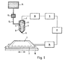
- eine Prinzipdarstellung -teilweise als Blockschaltbild- einer Vorrichtung zur Herstellung von Analyseelementen,
- Fig. 2
- einen auf der Erfindung basierenden Analyseautomat in einer perspektivischen Prinzipdarstellung,
- Fig. 3
- eine Aufsicht auf einen Reagenzbereich eines Analyseelementes,
- Fig. 4
- zwei Eichkurven zu Beispiel 4.
- Fig. 1
- 2 shows a schematic diagram, partly as a block diagram, of a device for producing analysis elements,
- Fig. 2
- an automatic analyzer based on the invention in a perspective diagram,
- Fig. 3
- a top view of a reagent area of an analysis element,
- Fig. 4
- two calibration curves for example 4.
Fig. 1 zeigt, wie Reagenzflüssigkeiten als vorbestimmtes Muster von Kompartimenten auf den Reagenzbereich 1 eines Analyseelementes 2 appliziert werden können. Der Begriff "Kompartiment" (englisch: compartment) bezeichnet dabei einen abgegrenzten Teilbereich. Über dem Reagenzbereich 1 ist ein insgesamt mit 3 bezeichneter Düsenkopf mit einer Düsenkammer 4 und einer Düse 5 angeordnet. In der Düsenkammer 4 befindet sich ein Heizelement 7, welches in thermischem Kontakt zu in der Düsenkammer 4 enthaltener Analyseflüssigkeit 6 steht. Von einer Steuereinheit 8 gesteuert wird über einen Impulsgeber 9 und einen Verstärker 10 jeweils ein Stromimpuls an das Heizelement 7 angelegt, wenn ein Quantum Analyseflüssigkeit 6 aus der Düse 5 ausgestoßen werden soll. Dabei bildet sich sehr schnell (innerhalb von ca. 200 µsec) eine Dampfblase 11. Durch deren Expansion wird ein Flüssigkeitstropfen aus der Düse 5 ausgestoßen. Die Düsenkammer 4 ist über eine Leitung 12 mit Filter 13 mit einem Vorratsbehälter 14 für Analyseflüssigkeit 6 verbunden. Düsenkopf 3, Filter 13 und Vorratsbehälter 14 können in einer disposiblen Cartridge ("Düseneinheit") untergebracht sein.1 shows how reagent liquids can be applied as a predetermined pattern of compartments to the reagent area 1 of an
Das Analyseelement 2 läßt sich mit Hilfe eines ebenfalls von der Steuereinheit 8 gesteuerten X-Y-Antriebs 15 und eines Positioniertisches 16 in beide Flächenrichtungen des Reagenzbereiches 1 so positionieren, daß nacheinander aus der Düse 5 ausgestoßene Reagenzflüssigkeitsquanten ein vorbestimmtes Muster bilden. Selbstverständlich kann alternativ oder zusätzlich auch der Düsenkopf 3 entsprechend bewegt werden.The
In Fig. 1 ist ein Düsenkopf 3 mit nur einem Heizelement 7 und einer Düse 5 dargestellt. Vorteilhafterweise können jedoch die für Tintenstrahl-Druckverfahren gebräuchlichen Düsenköpfe mit einer Mehrzahl von Düsen (meist 9, 12 oder 24 Düsen) verwendet werden. Dadurch kann die erforderliche Bewegung des Analyseelements 2 bei der Erzeugung eines vorbestimmten Musters reduziert und die Dosierleistung erhöht werden. Insbesondere ist es möglich, mit einer Relativbewegung des Analyseelements 2 bezüglich des Düsenkopfes 3 in nur einer Raumrichtung ein zweidimensionales Muster der Analyseflüssigkeit 6 auf der Reagenzfläche 1 zu erzeugen. Bei Verwendung eines Düsenkopfes 3 mit mehreren Kanälen ist selbstverständlich der Impulsgeber 9 und der Verstärker 10 entsprechend mehrkanalig ausgelegt.1 shows a
Abgesehen von den hier beschriebenen Besonderheiten können die für die Bubble-Jet-Technik bekannten konstruktiven Elemente bei der Erfindung verwendet werden. Es ist deshalb nicht erforderlich, auf konstruktive Einzelheiten der Vorrichtung, insbesondere der Düsenkammer, der Düse oder der Heizelemente einzugehen. Diese Angaben können der Literatur über Bubble-Jet-Tintenstrahldrucker entnommen werden.In addition to the special features described here, the structural elements known for bubble jet technology can be used in the invention. It is therefore not necessary to go into structural details of the device, in particular the nozzle chamber, the nozzle or the heating elements. This information can be found in the literature on bubble jet inkjet printers.
Wie oben dargelegt besteht ein besonderer Vorteil der Erfindung darin, daß eine so kostengünstige Herstellung einer Düseneinheit möglich ist, daß sie als disposibles Element gestaltet sein kann, welches einen Vorrat an Analyseflüssigkeit benutzungsfertig (herstellerseitig vorgepackt) enthält. Dadurch entfallen aufwendige habungsschritte bei der Durchführung von Analysen mit entsprechenden Geräten. So ist es möglich, mit verhältnismäßig geringem konstruktivem Aufwand außerordentlich vielseitig einsetzbare und einfach bedienbare Analysesysteme (bestehend aus Gerät und spezifisch darauf abgestimmten Reagenzien) zur Verfügung zu stellen. Ein solches System ist beispielhaft in Fig. 2 dargestellt.As stated above, a particular advantage of the invention is that it is possible to produce a nozzle unit so inexpensively that it can be designed as a disposable element which contains a supply of analysis liquid ready for use (prepacked by the manufacturer). This eliminates the need for time-consuming steps when carrying out analyzes with the appropriate devices. This makes it possible to provide extremely versatile and easy-to-use analysis systems (consisting of a device and specifically tailored reagents) with relatively little design effort. Such a system is shown by way of example in FIG. 2.
Bei dem in Fig. 2 dargestellten Gerät wird als Analyseelement ein Band 20 eingesetzt, welches aus einem geeigneten Reagenz-Trägermaterial, beispielsweise Papier oder einer Kunststoffolie besteht. Es wird schrittweise von einer Anfangsrolle 21 zu einer Endrolle 22 transportiert. Über dem Band 20 sind in einer Reagenzdosierstation 23 mehrere geräteseitige Halterungen 24 angeordnet, die mit Halterungselementen 27 an den Düseneinheiten 25 zusammenwirken, um diese auswechselbar an definierten Positionen über dem Band 20 zu positionieren. An den Halterungen 24 und an den Düseneinheiten 25 sind jeweils elektrische Kontakte 24a, 25a vorgesehen, die eine elektrische Verbindung zwischen dem Gerät und einer in eine Halterung 24 eingesetzten Düseneinheit ermöglichen.In the device shown in FIG. 2, a
In Transportrichtung des Bandes 20 (Pfeil 26) hinter der Reagenzdosierstation 23 befinden sich weitere Bearbeitungseinheiten, im dargestellten Fall eine Probendosiereinheit 28, zwei Wascheinheiten 29a, 29b, eine weitere Reagenzdosierstation 31 und eine Meßeinheit 30.In the transport direction of the belt 20 (arrow 26) behind the
Das Analyseverfahren beginnt damit, daß Analyseflüssigkeiten, insbesondere Reagenzien durch eine oder mehrere der Düseneinheiten 25 der Reagenzdosierstation 23 auf das Band 20 appliziert werden, die auf dem Band Reagenzbereiche 32 bilden. Um die gewünschte Flächenausdehnung der Reagenzbereiche 32 senkrecht zu der Transportrichtung 26 zu gewährleisten, haben die Düseneinheiten 25 mehrere nebeneinanderangeordnete Düsen in ihrem Düsenkopf 3. Alternativ oder zusätzlich können sie mit einer nicht dargestellten Mechanik quer zur Transportrichtung 26 des Bandes 20 beweglich sein.The analysis method begins with analysis liquids, in particular reagents, being applied to the
Durch die Probendosiereinheit 28 wird eine Probe zugegeben. Die Wascheinheiten 29a und 29b erlauben erforderlichenfalls die Durchführung von Waschschritten. Die Reagenzdosierstation 31 erlaubt die Dosierung eines weiteren Reagenzes. Die Meßeinheit 30 dient dazu, eine für die Analyse charakteristische physikalische Meßgröße, beispielsweise die optische Reflexion oder Fluoreszenz bei einer bestimmten Meßwellenlänge zu messen.A sample is added by the
Auf nähere Einzelheiten möglicher Verfahrensführungen wird hier nicht eingegangen. Die Erfindung kann bei einer Vielzahl verschiedener Verfahren (z.B. homogene und heterogene Immunoassays, enzymatische Bestimmungen etc.) eingesetzt werden, bei denen ein Analyseelement nach der Zuführung der Reagenzflüssigkeit in einem kontinuierlichen Prozeß zu einer Probenzugabestation transportiert, eine Probe mit der Reaktionsfläche kontaktiert und eine in Folge der Reaktion von Probe und Reagenz eintretende physikalisch meßbare Veränderung gemessen wird. Diese Verfahrensweise wurde bereits früher, insbesondere in der US-A-3 526 480 vorgeschlagen, auf welche hier Bezug genommen wird.No further details are given here of possible procedures. The invention can be used in a large number of different methods (for example homogeneous and heterogeneous immunoassays, enzymatic determinations, etc.) in which an analysis element, after the supply of the reagent liquid, is transported in a continuous process to a sample addition station, a sample is contacted with the reaction surface and an in As a result of the reaction of the sample and the reagent, a physically measurable change is measured. This procedure has been proposed earlier, in particular in US-A-3,526,480, to which reference is made here.
Entscheidend im Zusammenhang mit der vorliegenden Erfindung ist, daß bezüglich der Reagenzzugabe eine sehr einfache und flexible Anpassung an die Erfordernisse der jeweiligen Analyse möglich ist. So kann das Gerät durch einfaches Auswechseln der Düseneinheiten 25 auf verschiedene Analysen, die mit verschiedenen Reagenzien arbeiten, umgestellt werden, ohne daß Reagenzbehälter ausgetauscht und die üblicherweise verwendeten Zuführungsschläuche sowie Dosierungssysteme gespült werden müssen. Die Anordnung mehrerer Düsenelementhalterungen entlang der Transportbahn eines schrittweise in einem kontinuierlichen Prozeß transportierten Analyseelementes ermöglicht es, einerseits mehrere verschiedene Reagenzien zu verschiedenen Zeitpunkten zu dosieren und andererseits auch für ein einzelnes Reagenz die Zeit, die zwischen der Applikation auf dem Analyseelement und der Probenzugabe verstreicht, in einfacher Weise den jeweiligen Erfordernissen anzupassen.It is crucial in connection with the present invention that a very simple and flexible adaptation to the requirements of the respective analysis is possible with regard to the addition of the reagent. Thus, the device can be converted to different analyzes that work with different reagents by simply replacing the
Ein derartig einfacher Aufbau war bisher nur mit Hilfe vorgefertigter Analyseelemente, wie sie insbesondere in der äußeren Form von Teststreifen oder als sogenannte "analysis slides" gebräuchlich sind, möglich. Dies erforderte jedoch eine aufwendige Transportmechanik für die Analyseelemente. Darüber hinaus mußten die Analyseelemente zwischen Herstellung und Verwendung über längere Zeit gelagert werden. Damit ist in Anbetracht der problematischen Lagerstabilität solcher Analyseelemente ein hoher Aufwand verbunden. Die Erfindung ermöglicht es, das Analyseelement mit einer die gewünschte Reagenzkombination enthaltenden Reagenzfläche unmittelbar vor der Verwendung (d.h. vor der Zugabe der Probe) auf einfache Weise frisch herzustellen.Such a simple structure has so far been possible only with the aid of prefabricated analysis elements, as are particularly common in the outer form of test strips or as so-called "analysis slides". However, this required complex transport mechanics for the analysis elements. In addition, the analysis elements had to be stored for a long time between manufacture and use. In view of the problematic storage stability of such analysis elements, this involves a great deal of effort. The invention makes it possible to produce the analytical element in a simple manner fresh with a reagent surface containing the desired reagent combination immediately before use (ie before adding the sample).
Das kontinuierlich transportierte Analyseelement muß nicht notwendigerweise bandförmig gestaltet sein. Je nach den Erfordernissen der Analyse könnten auch kleine Reaktionsgefäße, beispielsweise in Form von miteinander verketteten flachen Schalen aus Kunststoff oder andere kontinuierlich transportierbare Reagenzträger verwendet werden.The continuously transported analysis element does not necessarily have to be designed in the form of a band. Depending on the requirements of the analysis, small reaction vessels, for example in the form of interlinked flat plastic shells or other continuously transportable reagent carriers, could also be used.
Die Erfindung kann vorteilhaft für die Applikation der verschiedensten in der klinischen Chemie üblichen Reagenzien auf einem festen Träger verwendet werden. Beispielsweise können Enzyme, Substrate oder andere lösliche Reaktionsbestandteile so auf den Träger aufgebracht werden, daß sie leicht eluierbar sind, um in flüssiger Phase zu reagieren. Aber auch für die Applikation von trägerfixierten Reagenzien (insbesondere Antikörper, Antigene etc.) kann die Erfindung vorteilhaft eingesetzt werden. Schließlich kann es zweckmäßig sein, auf der Trägeroberfläche, auf die die Applikation nach dem erfindungsgemäßen Verfahren erfolgt, bereits zuvor nach anderen Verfahren Reaktionsbestandteile aufzubringen. So kann beispielsweise ein Trägermaterial großflächig mit einer Streptavidin enthaltenden Oberflächenbeschichtung versehen sein, auf welche selektiv und gezielt biotinylierte Reagenzien appliziert werden, welche über die Biotin-Streptavidin-Bindung an den Träger gebunden werden. Nähere Einzelheiten sind in der EP0 469 445 A1 beschrieben, auf welche hier Bezug genommen wird.The invention can advantageously be used for the application of a wide variety of reagents customary in clinical chemistry on a solid support. For example, enzymes, substrates or other soluble reaction components can be applied to the support in such a way that they are easy to elute in order to react in the liquid phase. However, the invention can also be used advantageously for the application of carrier-fixed reagents (in particular antibodies, antigens, etc.). Finally, it may be expedient to apply reaction components beforehand by other methods to the carrier surface to which the application according to the method of the invention is applied. For example, a large area of a support material can be provided with a surface coating containing streptavidin, to which selectively and selectively biotinylated reagents are applied, which are bound to the support via the biotin-streptavidin bond. Further details are described in EP0 469 445 A1, to which reference is made here.
Wenn gemäß dem erfindungsgemäßen Verfahren eine Mehrzahl verschiedener Reagenzflüssigkeiten auf einen Reagenzbereich aufgebracht wird, ist es vorteilhaft, das Applikationsmuster so zu wählen, daß die von Quanten verschiedener Reagenzflüssigkeiten erzeugten Kompartimente sich gegenseitig nicht kontaktieren. Dies gilt insbesondere, wenn die in den Flüssigkeiten enthaltenen Reagenzien miteinander (zumindest im flüssigen Zustand) interferieren. Vorzugsweise bilden dabei die Quanten verschiedener Reagenzflüssigkeiten ein Muster von alternierenden Kompartimenten, wobei sie dicht beieinander, aber räumlich getrennt, vorliegen. Auch insoweit wird auf die genannte gleichzeitig eingereichte Anmeldung Bezug genommen.If, according to the method according to the invention, a plurality of different reagent liquids are applied to a reagent area, it is advantageous to choose the application pattern in such a way that the quantum differs Compartments produced reagent liquids do not contact each other. This applies in particular if the reagents contained in the liquids interfere with one another (at least in the liquid state). In this case, the quanta of different reagent liquids preferably form a pattern of alternating compartments, where they are close to one another but spatially separated. In this respect, too, reference is made to the aforementioned simultaneously filed application.
Ein solches Kompartimentmuster ist in Fig. 3 dargestellt.Such a compartment pattern is shown in FIG. 3.
Die Quanten der Reagenzflüssigkeit bilden im dargestellten Beispiel eine Mehrzahl von reihenförmigen Kompartimenten 35, die jeweils aus vielen dicht beieinander geordneten Flächenelementen ("Dots") 36 bestehen, die jeweils von einem Quantum der Reagenzflüssigkeit erzeugt sind. Für den Fall, daß der Träger in einem kontinuierlichen Prozeß, wie er in Fig. 2 dargestellt ist, mit der Reagenzflüssigkeit beschickt wird, können die verschiedenen Kompartimente der gleichen Reagenzzusammensetzung zweckmäßigerweise aus verschiedenen Düsen der gleichen Düseneinheit 25 ausgestoßen werden. Die Transportrichtung verläuft in diesem Fall parallel zu den Reihen (Pfeil 26).In the example shown, the quanta of the reagent liquid form a plurality of row-shaped
Die am oberen Rand der Fig. 3 angegebenen Buchstaben bezeichnen drei verschiedene Sätze A,B,C, von Kompartimenten 35, wobei die Kompartimente 35 des gleichen Satzes die gleichen Reagenzien enthalten, während die Reagenzien verschiedener Sätze sich in ihrer chemischen Zusammensetzung unterscheiden.The letters given at the top of FIG. 3 designate three different sets A, B, C, of
Statt der dargestellten alternierenden Reihen können auch andere Formen von Flächenelementen verwendet werden. Insbesondere kann ein Punktmuster, welches aus sich gegenseitig nicht überlappenden Dots besteht, (so daß jeweils ein Dot ein Kompartiment bildet), zweckmäßig sein.Instead of the alternating rows shown, other shapes of surface elements can also be used. Especially a dot pattern consisting of dots that do not overlap each other (so that one dot forms a compartment) can be useful.
Im dargestellten Beispielsfall haben die Dots innerhalb der Kompartimente einen Mittenabstand von wenig mehr als 0,1 mm. Der Mittenabstand der Kompartimente voneinander beträgt ca. 0,26 mm. Dabei wurde von den drucktechnisch möglichen Kompartimenten nur jedes zweite verwendet. Grundsätzlich ist ein noch engerer Abstand der Flächenelemente möglich.In the example shown, the dots within the compartments have a center distance of little more than 0.1 mm. The center distance of the compartments from each other is approx. 0.26 mm. Of the compartments that were technically possible, only every second was used. In principle, an even closer spacing of the surface elements is possible.
Im Rahmen der vorliegenden Erfindung wurde festgestellt, daß eine solch enge mit dem erfindungsgemäßen Verfahren hergestellte Anordnung von aus verschiedenen Reagenzflüssigkeiten bestehenden Flächenelementen in vielen Fällen vorteilhafte Analyseverfahren ermöglicht. Soweit bisher verschiedene miteinander unverträgliche Reagenzien in einem Analyseelement verwendet wurden, wurden diese in aller Regel in verschiedene Schichten eines mehrschichtigen Analyseelements integriert, wobei diese Schichten entweder separat hergestellt und anschließend zusammengefügt wurden oder nacheinander in einem schichtbildenden Verfahren auf eine Basisschicht aufgetragen wurden. Zwar wurde in der DE-C2-27 29 333 bereits vorgeschlagen, miteinander unverträgliche Reagenzien im Siebdruckverfahren auf eine Fläche derartig aufzutragen, daß die Flächenelemente alternieren. Dieses bekannte Verfahren ist jedoch sehr aufwendig und erfordert lange Reaktionszeiten. In Verbindung mit dem erfindungsgemäßen Verfahren ist auf einfache Weise ein so enger Abstand der Flächenelemente möglich, daß sich nach Aufgabe der Probe die verschiedenen Reagenzien schnell praktisch vollständig mischen und homogen reagieren.In the context of the present invention, it was found that such a close arrangement of surface elements consisting of different reagent liquids produced by the method according to the invention enables advantageous analysis methods in many cases. To the extent that different mutually incompatible reagents have been used in one analysis element, these have generally been integrated into different layers of a multilayer analysis element, these layers either being produced separately and then joined together or being applied successively to a base layer in a layer-forming process. It has already been proposed in DE-C2-27 29 333 to apply reagents which are incompatible with one another in a screen printing process on a surface in such a way that the surface elements alternate. However, this known method is very complex and requires long reaction times. In connection with the method according to the invention, such a close spacing of the surface elements is possible in a simple manner that the various reagents quickly mix completely practically and react homogeneously after the sample has been applied.
Die folgenden Beispiele dienen der weiteren Erläuterung der Erfindung.The following examples serve to further explain the invention.
Die Tinte eines nach dem Bubble-Jet-Prinzip arbeitenden Tintenstrahl-Druckkopfes (Hewlett-Packard Typ Quiet Jet plus) wird gegen eine Tartrazin-Farbstofflösung ausgetauscht.The ink of a bubble jet print head (Hewlett-Packard type Quiet Jet plus) is exchanged for a tartrazine dye solution.
Daten des Druckkopfes:
- 12 Düsen in Reihe angeordnet
- Tropfendurchmesser ca. 75 µm
- kleinstes dosierbares Quantum (1 Tropfen) 230 Pikoliter
- maximale Druckdichte pro Druckschritt: 192 x 192 Tropfen/inch2
- 12 nozzles arranged in a row
- Drop diameter approx. 75 µm
- smallest quantifiable quantity (1 drop) 230 picoliters
- maximum printing density per printing step: 192 x 192 drops / inch 2
Dieser Druckkopf ist zusammen mit einem Tintenvorratsbehälter in einer entnehmbaren Cartridge untergebracht. Die Steuerung des Druckkopfes erfolgt über einen Personal Computer mit Hilfe eines Basic-Steuerprogramms.This print head is housed together with an ink reservoir in a removable cartridge. The print head is controlled by a personal computer using a basic control program.
Volumina zwischen 0,1 und 5 µl der Farbstofflösung (40 mg/ml Tartrazin in 40 mM Natriumphosphat-Puffer (NaPP) pH 7,4) wurden in Reagenzröhrchen, die mit 2 ml destilliertem Wasser gefüllt waren, dosiert. Anschließend wurde in einem kommerziell erhältlichen Analysegerät (ES 22 der Boehringer Mannheim GmbH) sorgfältig gemischt und die Extinktion bei 405 nm gemessen. Die Präzision der Dosierung wurde anhand von 15-fach Bestimmungen errechnet. Die Ergebnisse sind in Tabelle 1 dargestellt.Volumes between 0.1 and 5 ul of the dye solution (40 mg / ml tartrazine in 40 mM sodium phosphate buffer (NaPP) pH 7.4) were metered into test tubes which were filled with 2 ml of distilled water. The mixture was then mixed thoroughly in a commercially available analyzer (
Bei diesem Beispiel wurde analog zu Beispiel 1 eine Lösung von 0,5 mg/ml des Enzyms Peroxidase in 40 mM NaPP pH 7,4, 3 Gewichts-% Polyvinylpyrrolidon, 0,01 Gewichts-% Triton-X-100 dosiert. In den Röhrchen war in diesem Fall jeweils 2 ml ABTSR-Substratlösung (1,9 mmol/l 2,2'-Azino-di-[3-äthyl-benzthiazolin-sulfonsäure(6)] -diammoniumsalz; 100 mmol/l Phosphat-Citrat-Puffer pH 4,4; 2,2 mmol/l Natriumperborat) vorgelegt. Die dosierten Volumina lagen zwischen 0,23 und 80 nl. Die Bestimmung der Extinktionen und der Dosierpräzisionen erfolgten analog zu Beispiel 1.In this example, a solution of 0.5 mg / ml of the enzyme peroxidase in 40 mM NaPP pH 7.4, 3% by weight of polyvinylpyrrolidone, 0.01% by weight of Triton-X-100 was metered in as in Example 1. In this case, each tube contained 2 ml of ABTS R substrate solution (1.9 mmol /
Die Ergebnisse von Beispiel 2 sind in der Tabelle 2 dargestellt.
In den Tabellen ist jeweils das Soll-Volumen und der Variationskoeffizient VK angegeben. Die VK-Werte, die sich auf jeweils 15 Messungen beziehen, zeigen, daß die Präzision der Dosierung (in Relation zu den sehr geringen Volumina) ausgezeichnet ist.The target volume and the coefficient of variation VK are given in the tables. The VK values, which refer to 15 measurements each, show that the precision of the dosage (in relation to the very small volumes) is excellent.
Mit einem Druckkopf entsprechend den Beispielen 1 und 2 wird eine Reagenzflüssigkeit mit folgender Zusammensetzung verarbeitet:
Die Beschichtungslösung wird mit maximaler Druckdichte (192x192 Tropfen/inch2) auf ein saugfähiges Papier aufgebracht, wobei sechs getrennte Reagenzflächen erzeugt werden. Der Auftrag wird dreimal wiederholt, wobei die insgesamt applizierte Menge an Reagenzflüssigkeit etwa 3,9 µl/cm2 beträgt. Anschließend wird bei Raumtemperatur getrocknet (ca. 30 min.) oder sofort die Probe aufgetragen.The coating solution is applied at maximum pressure density (192x192 drops / inch 2 ) to an absorbent paper, whereby six separate reagent areas are generated. The application is repeated three times, the total amount of reagent liquid applied being approximately 3.9 μl / cm 2 . Then it is dried at room temperature (approx. 30 min.) Or the sample is applied immediately.
Trägt man auf die so erhaltenen sechs Reagenzflächen jeweils 1 µl Probe mit unterschiedlichen Sarcosin-Konzentrationen zwischen 0 und 100 mM auf, so ergibt sich nach etwa 1 min ein gut abgestufter Farbumschlag, der in üblicher Weise kalibriert und reflexionsphotometrisch vermessen werden kann. Die visuelle Detektionsgrenze liegt bei ca. 10 ng Sarcosin/µl.If 1 µl sample with different sarcosine concentrations between 0 and 100 mM is applied to each of the six reagent areas thus obtained, a well-graded color change results after about 1 min, which can be calibrated in the usual manner and measured by reflection photometry. The visual detection limit is approx. 10 ng sarcosine / µl.
Das Beispiel zeigt, daß erfindungsgemäß auch ein mit relativ hohen Reagenzmengen arbeitendes Analyseelement für einen enzymatischen Test auf einfache Weise hergestellt werden kann. Gegenüber konventionellen Tests ergibt sich eine bedeutende Ersparnis an Reagenz und es kann mit einer sehr kleinen Probenmenge gearbeitet werden. Die niedrige Nachweisgrenze zeigt, daß die Enzymaktivität praktisch vollständig erhalten geblieben ist.The example shows that, according to the invention, an analysis element for an enzymatic test that works with relatively large amounts of reagent can also be produced in a simple manner. Compared to conventional tests, there is a significant saving in reagent and it can be done with one very small amount of sample can be worked. The low detection limit shows that the enzyme activity is practically completely preserved.
Eine Analyse des Schilddrüsen-Hormons TSH wird einerseits mit einem konventionellen Immun-Analysesystem (Enzymunsystem ES 22 der Boehringer Mannheim GmbH, Versuch A) und andererseits mit einem erfindungsgemäß modifizierten System (Versuch B) durchgeführt. Die einzelnen Schritte laufen bei Versuch B wie folgt ab:
- a) Es werden mit Streptavidin beschichtete Polystyrol-Tubes (Herstellung nach EP-A-0344578) verwendet. In diese werden jeweils 100 µl Probe bzw. Standard dosiert.
- b) Mit Hilfe eines Druckkopfes wie bei den Beispielen 1-3
wird 10 µl einer über einen 0,8 µm Filter filtrierten Konjugatlösung appliziert. Die Konjugatlösung enthält 18 U/ml eines Konjugates aus einem gegen TSH gerichteten monoklonalen Antikörper (ECACC 87122202) und Peroxidase in 80 mM Natriumphosphat-Puffer (NaPP) pH 7,4. - c) Über die Dosiereinheit des genannten Systems wird 1 min nach Zugabe des Konjugates 1ml Inkubationspuffer (80 mM NaPP pH 7,4 mit 1250 µg/ml eines biotinylierten monoklonalen Antikörpers gegen TSH (ECACC 87122201), 2g/l Rinder-Serumalbumin, 1 g/l Rinder-IgG) zudosiert. (Die Biotinylierung des Antikörpers erfolgte gemäß JACS 100 (1978,3585-3590) durch Umsetzung mit N-hydroxysuccinimid-Biotin im Verhältnis 10:1).
- d) Anschließend wird für 60 min inkubiert.
- e) Mit der Dosiereinheit des verwendeten Systems werden fünf Waschschritte, jeweils bestehend aus Absaugen der Reagenzlösung und Zudosierung von Leitungswasser durchgeführt.
- f) Wiederum über die Dosiereinheit wird 1 ml Enzymun-ABTSR-Substratlösung zudosiert.
- g) Es wird für 30 min inkubiert.
- h) Die Extinktion der Substratlösung wird mit Hilfe der photometrischen Meßeinrichtung des Systems bei 405 nm vermessen.
- a) Polystyrene tubes coated with streptavidin (production according to EP-A-0344578) are used. 100 µl of sample or standard are dosed into each.
- b) Using a printhead as in Examples 1-3, 10 μl of a conjugate solution filtered through a 0.8 μm filter is applied. The conjugate solution contains 18 U / ml of a conjugate of a monoclonal antibody directed against TSH (ECACC 87122202) and peroxidase in 80 mM sodium phosphate buffer (NaPP) pH 7.4.
- c) 1 ml of incubation buffer (80 mM NaPP pH 7.4 with 1250 µg / ml of a biotinylated monoclonal antibody against TSH (ECACC 87122201), 2 g / l bovine serum albumin, 1 g / l bovine IgG) added. (The antibody was biotinylated according to JACS 100 (1978, 35585-3590) by reaction with N-hydroxysuccinimide biotin in a ratio of 10: 1).
- d) Then incubate for 60 min.
- e) With the dosing unit of the system used, five washing steps, each consisting of suctioning off the reagent solution and metering in tap water, are carried out.
- f) 1 ml of Enzymun-ABTS R substrate solution is again metered in via the metering unit.
- g) It is incubated for 30 min.
- h) The absorbance of the substrate solution is measured using the system's photometric measuring device at 405 nm.
Bei dem konventionellen Vergleich (Versuch A) werden die Schritte b und c zusammengefaßt. Das Konjugat aus Schritt b ist in diesem Fall in einer Konzentration von 18 U/ml in dem unter Schritt c beschriebenen Inkubationspuffer zugesetzt. 1 ml dieser Gesamtlösung wird über die Dosiereinheit des genannten Systems zudosiert.In the conventional comparison (experiment A), steps b and c are combined. In this case, the conjugate from step b is added in a concentration of 18 U / ml in the incubation buffer described under step c. 1 ml of this total solution is added via the dosing unit of the system mentioned.
Die Eichung erfolgt mit üblichen Standards zwischen 0 und 51,1 µU TSH/ml.
In Tabelle 3 sind die Ergebnisse für zwei verschiedene Sollwerte (1,9 µU/ml und 6,0 µU/ml) von Kontrollseren mit jeweils 12 Messungen einerseits für den erfindungsgemäßen modifizierten Verfahrensablauf und andererseits für den Vergleichsversuch wiedergegeben. Es werden vergleichbare Ergebnisse hinsichtlich Präzision und Wiederfindung des Sollwertes erreicht.Table 3 shows the results for two different setpoints (1.9 μU / ml and 6.0 μU / ml) of control sera, each with 12 measurements, on the one hand for the modified process sequence according to the invention and on the other hand for the comparison test. Comparable results regarding precision and recovery of the setpoint are achieved.
Fig. 4 zeigt die Eichkurven der Versuche A und B, d.h. die Extinktion E in Abhängigkeit von der Konzentration von Standardlösungen. Die Tatsache, daß beide Kurven sehr eng übereinstimmen, ist ein weiterer Beleg dafür, daß die Eigenschaften proteinhaltiger Lösungen, im vorliegenden Fall des Antikörper-Enzymkonjugates, durch die Applikation mit dem erfindungsgemäßen Verfahren praktisch nicht verändert werden.Fig. 4 shows the calibration curves of tests A and B, i.e. the absorbance E depending on the concentration of standard solutions. The fact that the two curves correspond very closely is further evidence that the properties of protein-containing solutions, in the present case the antibody-enzyme conjugate, are practically not changed by the application with the method according to the invention.
Dieses Ergebnis belegt in besonderem Maße die Eignung des erfindungsgemäßen Verfahrens zur Dosierung von sehr kleinen Quanten von Reagenzflüssigkeit, weil der Analyt TSH in einer extrem niedrigen Konzentration gegenwärtig ist.This result confirms in particular the suitability of the method according to the invention for dosing very small quanta of reagent liquid, because the analyte TSH is present in an extremely low concentration.
Claims (11)
- A method for the metered application of an analytical liquid containing biochemical macromolecules to a target, wherein this liquid is ejected in small quantities on to the target through a jet from a jet chamber, characterized in that a partial volume of the liquid in the jet chamber is evaporated and expanded for a short time in order to eject each quantity of the liquid through the jet.
- A method according to Claim 1, characterized in that the analytical liquid is a liquid reagent.
- A method according to Claim 1 or Claim 2,
characterized in that the analytical liquid contains a protein, especially a binding protein, an enzyme, an antibody, an antibody-enzyme conjugate, an antigen, a hapten or a substrate. - A method according to any one of the preceding claims, characterized in that the target is a reaction vessel into which the analytical liquid is introduced.
- A method according to Claim 2 or Claim 3,
characterized in that the target is a reagent domain of an analysis element, several quantities of liquid reagent are ejected successively and the jet and the analysis element are moved relative to one another in such a way that the dots produced by the quantities of liquid reagent in the reagent domain form a predetermined pattern of compartments in the reagent domain. - A method according to Claim 5, characterized in that the analysis element, after application of the liquid reagent, is conveyed in a continuous process to a sample delivery station, a sample is brought into contact with the reagent domain and a physically measurable change occurring as a consequence of the reaction between sample and reagent is measured.
- A method according to Claim 5 or Claim 6,
characterized in that several different liquid reagents are each ejected from a separate jet chamber through separate jets. - A method according to Claim 7, characterized in that there is essentially no contact between the compartments produced by quantities of different liquid reagents in the predetermined pattern.
- A method according to Claim 8, characterized in that the quantities of different liquid reagents form a pattern of alternating dots in which quantities of different liquid reagents are adjacent but spatially separated.
- A method according to any one of Claims 5 to 9,
characterized in that a dot produced by a quantity of liquid reagent on the reagent domain has a surface area of less than 2 mm2. - A device for the metered application of an analytical liquid containing biochemical macromolecules to a target, wherein this analytical liquid is contained in a jet chamber of a disposable jet element (25), provided with a jet (5), prepacked by the manufacturer, characterized in that the jet chamber (4) has a heating element (11) in thermal contact with the liquid, by means of which a partial volume of the analytical liquid (6) can be evaporated and expanded for a short time in order to eject a quantity of the analytical liquid (6) through the jet (5), and a fixing element (27) and electrical contacts (25a) are provided on the outside of the jet element (25) for interchangeably connecting the jet element mechanically and electrically to an analyzer.
Applications Claiming Priority (2)
| Application Number | Priority Date | Filing Date | Title |
|---|---|---|---|
| DE4024545A DE4024545A1 (en) | 1990-08-02 | 1990-08-02 | Metered delivery of biochemical analytical soln., esp. reagent |
| DE4024545 | 1990-08-02 |
Publications (2)
| Publication Number | Publication Date |
|---|---|
| EP0469444A1 EP0469444A1 (en) | 1992-02-05 |
| EP0469444B1 true EP0469444B1 (en) | 1997-06-04 |
Family
ID=6411511
Family Applications (1)
| Application Number | Title | Priority Date | Filing Date |
|---|---|---|---|
| EP91112388A Expired - Lifetime EP0469444B1 (en) | 1990-08-02 | 1991-07-24 | Method and apparatus for disparsing biochemical reagents onto a target in precisely controlled volumes |
Country Status (17)
| Country | Link |
|---|---|
| US (1) | US5338688A (en) |
| EP (1) | EP0469444B1 (en) |
| JP (1) | JP2524439B2 (en) |
| KR (1) | KR920004836A (en) |
| AT (1) | ATE154127T1 (en) |
| AU (1) | AU633446B2 (en) |
| CA (1) | CA2047636C (en) |
| DE (2) | DE4024545A1 (en) |
| DK (1) | DK0469444T3 (en) |
| ES (1) | ES2103760T3 (en) |
| FI (1) | FI913669A (en) |
| IE (1) | IE912537A1 (en) |
| IL (1) | IL99042A0 (en) |
| NO (1) | NO912999L (en) |
| NZ (1) | NZ239059A (en) |
| PT (1) | PT98515A (en) |
| ZA (1) | ZA916055B (en) |
Cited By (1)
| Publication number | Priority date | Publication date | Assignee | Title |
|---|---|---|---|---|
| US8057756B2 (en) | 2005-01-28 | 2011-11-15 | Parker-Hannifin Corporation | Sampling probe, gripper and interface for laboratory sample management systems |
Families Citing this family (139)
| Publication number | Priority date | Publication date | Assignee | Title |
|---|---|---|---|---|
| US6040138A (en) | 1995-09-15 | 2000-03-21 | Affymetrix, Inc. | Expression monitoring by hybridization to high density oligonucleotide arrays |
| AU675054B2 (en) * | 1991-11-22 | 1997-01-23 | Affymetrix, Inc. | Combinatorial strategies for polymer synthesis |
| US6943034B1 (en) | 1991-11-22 | 2005-09-13 | Affymetrix, Inc. | Combinatorial strategies for polymer synthesis |
| DE4202850A1 (en) * | 1992-01-31 | 1993-08-05 | Boehringer Mannheim Gmbh | ANALYSIS ELEMENT FOR IMMUNOASSAYS |
| DE4202848A1 (en) * | 1992-01-31 | 1993-08-05 | Boehringer Mannheim Gmbh | ANALYSIS ELEMENT FOR IMMUNOASSAYS |
| JP2575270B2 (en) * | 1992-11-10 | 1997-01-22 | 浜松ホトニクス株式会社 | Method for determining base sequence of nucleic acid, method for detecting single molecule, apparatus therefor and method for preparing sample |
| US5605798A (en) | 1993-01-07 | 1997-02-25 | Sequenom, Inc. | DNA diagnostic based on mass spectrometry |
| US5666977A (en) * | 1993-06-10 | 1997-09-16 | Philip Morris Incorporated | Electrical smoking article using liquid tobacco flavor medium delivery system |
| ES2123162T3 (en) * | 1993-10-21 | 1999-01-01 | Abbott Lab | APPARATUS AND TRANSFER PROCEDURE OF A FLUID SAMPLE. |
| US7323298B1 (en) | 1994-06-17 | 2008-01-29 | The Board Of Trustees Of The Leland Stanford Junior University | Microarray for determining the relative abundances of polynuceotide sequences |
| US5807522A (en) * | 1994-06-17 | 1998-09-15 | The Board Of Trustees Of The Leland Stanford Junior University | Methods for fabricating microarrays of biological samples |
| US7378236B1 (en) | 1994-06-17 | 2008-05-27 | The Board Of Trustees Of The Leland Stanford Junior University | Method for analyzing gene expression patterns |
| US6558633B1 (en) * | 1994-09-21 | 2003-05-06 | Isis Pharmaceuticals, Inc. | Chemical reaction apparatus and methods |
| US5601980A (en) * | 1994-09-23 | 1997-02-11 | Hewlett-Packard Company | Manufacturing method and apparatus for biological probe arrays using vision-assisted micropipetting |
| US8236493B2 (en) | 1994-10-21 | 2012-08-07 | Affymetrix, Inc. | Methods of enzymatic discrimination enhancement and surface-bound double-stranded DNA |
| US6428955B1 (en) | 1995-03-17 | 2002-08-06 | Sequenom, Inc. | DNA diagnostics based on mass spectrometry |
| US5830655A (en) | 1995-05-22 | 1998-11-03 | Sri International | Oligonucleotide sizing using cleavable primers |
| SE9502251D0 (en) | 1995-06-21 | 1995-06-21 | Pharmacia Ab | Flow-through sampling cell and use thereof |
| EP0880598A4 (en) | 1996-01-23 | 2005-02-23 | Affymetrix Inc | Nucleic acid analysis techniques |
| AU2069597A (en) | 1996-03-04 | 1997-09-22 | Genetrace Systems, Inc. | Methods of screening nucleic acids using mass spectrometry |
| DE59704014D1 (en) * | 1996-03-05 | 2001-08-16 | Syngenta Participations Ag | TEST SYSTEM FOR CHEMICALS OR MIXTURES |
| US5958342A (en) * | 1996-05-17 | 1999-09-28 | Incyte Pharmaceuticals, Inc. | Jet droplet device |
| USRE38281E1 (en) | 1996-07-26 | 2003-10-21 | Biodot, Inc. | Dispensing apparatus having improved dynamic range |
| US5916524A (en) * | 1997-07-23 | 1999-06-29 | Bio-Dot, Inc. | Dispensing apparatus having improved dynamic range |
| US5965363A (en) | 1996-09-19 | 1999-10-12 | Genetrace Systems Inc. | Methods of preparing nucleic acids for mass spectrometric analysis |
| US7285422B1 (en) * | 1997-01-23 | 2007-10-23 | Sequenom, Inc. | Systems and methods for preparing and analyzing low volume analyte array elements |
| US6024925A (en) | 1997-01-23 | 2000-02-15 | Sequenom, Inc. | Systems and methods for preparing low volume analyte array elements |
| DE69727489T2 (en) | 1996-11-06 | 2004-11-25 | Sequenom, Inc., San Diego | METHOD OF MASS SPECTROMETRY |
| DE69735445T2 (en) | 1996-12-10 | 2006-08-10 | Sequenom, Inc., San Diego | NON-VOLATILE, NON-VOLATILE MOLECULES FOR MASS MARKING |
| DE19880001T1 (en) * | 1997-01-09 | 1999-03-18 | Mercury Diagnostics Inc | Method for applying a reagent to an analytical test device |
| DE19707204A1 (en) | 1997-02-24 | 1998-08-27 | Boehringer Mannheim Gmbh | System for the production of multiple diagnostic test elements |
| JP3352385B2 (en) * | 1997-03-21 | 2002-12-03 | キヤノン株式会社 | Electron source substrate and method of manufacturing electronic device using the same |
| US5985214A (en) | 1997-05-16 | 1999-11-16 | Aurora Biosciences Corporation | Systems and methods for rapidly identifying useful chemicals in liquid samples |
| EP1027159B1 (en) * | 1997-10-31 | 2002-04-03 | PE Corporation (NY) | Method and apparatus for making arrays of samples |
| US5882930A (en) * | 1997-11-10 | 1999-03-16 | Hyseq, Inc. | Reagent transfer device |
| US6268131B1 (en) | 1997-12-15 | 2001-07-31 | Sequenom, Inc. | Mass spectrometric methods for sequencing nucleic acids |
| US7470547B2 (en) * | 2003-07-31 | 2008-12-30 | Biodot, Inc. | Methods and systems for dispensing sub-microfluidic drops |
| US20020159919A1 (en) * | 1998-01-09 | 2002-10-31 | Carl Churchill | Method and apparatus for high-speed microfluidic dispensing using text file control |
| US6063339A (en) * | 1998-01-09 | 2000-05-16 | Cartesian Technologies, Inc. | Method and apparatus for high-speed dot array dispensing |
| US20060211132A1 (en) * | 1998-01-09 | 2006-09-21 | Rico Miledi | Method for high throughput drop dispensing of specific patterns |
| US6269846B1 (en) * | 1998-01-13 | 2001-08-07 | Genetic Microsystems, Inc. | Depositing fluid specimens on substrates, resulting ordered arrays, techniques for deposition of arrays |
| US6722395B2 (en) * | 1998-01-13 | 2004-04-20 | James W. Overbeck | Depositing fluid specimens on substrates, resulting ordered arrays, techniques for analysis of deposited arrays |
| US6407858B1 (en) | 1998-05-14 | 2002-06-18 | Genetic Microsystems, Inc | Focusing of microscopes and reading of microarrays |
| US6428752B1 (en) | 1998-05-14 | 2002-08-06 | Affymetrix, Inc. | Cleaning deposit devices that form microarrays and the like |
| DE19803292A1 (en) * | 1998-01-29 | 1999-08-05 | Joerg Frey | Robot for dosing liquids in amounts measured in microliters |
| US6537505B1 (en) | 1998-02-20 | 2003-03-25 | Bio Dot, Inc. | Reagent dispensing valve |
| FR2776389B1 (en) * | 1998-03-20 | 2000-06-16 | Fondation Jean Dausset Ceph | AUTOMATIC DEVICE FOR PRODUCING SAMPLES FOR THE IMPLEMENTATION OF CHEMICAL OR BIOLOGICAL REACTIONS IN A LIQUID MEDIUM |
| US7095032B2 (en) * | 1998-03-20 | 2006-08-22 | Montagu Jean I | Focusing of microscopes and reading of microarrays |
| DE19817531A1 (en) * | 1998-04-09 | 1999-10-21 | Diagnostikforschung Inst | Sequential synthesis or analysis involving multiple positions on flat substrate |
| US6350618B1 (en) | 1998-04-27 | 2002-02-26 | Corning Incorporated | Redrawn capillary imaging reservoir |
| US6884626B1 (en) | 1998-04-27 | 2005-04-26 | Corning Incorporated | Redrawn capillary imaging reservoir |
| EP0955084B1 (en) | 1998-04-27 | 2006-07-26 | Corning Incorporated | Method of depositing an array of biological samples using a redrawn capillary reservoir |
| US6723564B2 (en) | 1998-05-07 | 2004-04-20 | Sequenom, Inc. | IR MALDI mass spectrometry of nucleic acids using liquid matrices |
| US6762061B1 (en) | 1998-07-03 | 2004-07-13 | Corning Incorporated | Redrawn capillary imaging reservoir |
| US6551557B1 (en) | 1998-07-07 | 2003-04-22 | Cartesian Technologies, Inc. | Tip design and random access array for microfluidic transfer |
| US6830934B1 (en) * | 1999-06-15 | 2004-12-14 | Lifescan, Inc. | Microdroplet dispensing for a medical diagnostic device |
| US6521182B1 (en) * | 1998-07-20 | 2003-02-18 | Lifescan, Inc. | Fluidic device for medical diagnostics |
| US6461812B2 (en) * | 1998-09-09 | 2002-10-08 | Agilent Technologies, Inc. | Method and multiple reservoir apparatus for fabrication of biomolecular arrays |
| US6458583B1 (en) | 1998-09-09 | 2002-10-01 | Agilent Technologies, Inc. | Method and apparatus for making nucleic acid arrays |
| US6309891B1 (en) * | 1998-09-09 | 2001-10-30 | Incyte Genomics, Inc. | Capillary printing systems |
| DE19847421A1 (en) * | 1998-10-14 | 2000-04-20 | Easy Lab Gmbh | Laboratory pipette droplet are expelled to dish by electrostatic charge enhancing accuracy of the dose |
| US6689323B2 (en) * | 1998-10-30 | 2004-02-10 | Agilent Technologies | Method and apparatus for liquid transfer |
| US20030207464A1 (en) * | 1999-02-19 | 2003-11-06 | Tony Lemmo | Methods for microfluidic aspirating and dispensing |
| US6627157B1 (en) | 1999-03-04 | 2003-09-30 | Ut-Battelle, Llc | Dual manifold system and method for fluid transfer |
| GB9906477D0 (en) * | 1999-03-19 | 1999-05-12 | Pyrosequencing Ab | Liquid dispensing apparatus |
| DE19917029C2 (en) * | 1999-04-15 | 2001-08-09 | Inst Mikrotechnik Mainz Gmbh | Method and device for the metered dispensing of liquid quantities in the range from 0.1 nl to 100 mul |
| US6221653B1 (en) * | 1999-04-27 | 2001-04-24 | Agilent Technologies, Inc. | Method of performing array-based hybridization assays using thermal inkjet deposition of sample fluids |
| US6589791B1 (en) | 1999-05-20 | 2003-07-08 | Cartesian Technologies, Inc. | State-variable control system |
| AUPQ105599A0 (en) * | 1999-06-18 | 1999-07-08 | Proteome Systems Ltd | High resolution maldi analysis |
| US6346423B1 (en) | 1999-07-16 | 2002-02-12 | Agilent Technologies, Inc. | Methods and compositions for producing biopolymeric arrays |
| US6713309B1 (en) * | 1999-07-30 | 2004-03-30 | Large Scale Proteomics Corporation | Microarrays and their manufacture |
| KR100320752B1 (en) * | 1999-08-06 | 2002-01-17 | 박한오 | automated microarray of samples |
| US6426227B1 (en) * | 1999-08-31 | 2002-07-30 | Common Sense Ltd. | Method for analyzing secreted bodily fluids |
| DE19946525A1 (en) * | 1999-09-28 | 2001-05-03 | Fraunhofer Ges Forschung | Device for taking up and dispensing the smallest amounts of liquid |
| US6689319B1 (en) | 1999-10-29 | 2004-02-10 | Agilent Technologies, Ind. | Apparatus for deposition and inspection of chemical and biological fluids |
| US6446642B1 (en) | 1999-11-22 | 2002-09-10 | Agilent Technologies, Inc. | Method and apparatus to clean an inkjet reagent deposition device |
| US6399396B1 (en) | 2000-01-28 | 2002-06-04 | Agilent Technologies, Inc. | Compressed loading apparatus and method for liquid transfer |
| US20020003177A1 (en) * | 2000-03-17 | 2002-01-10 | O'connor Stephen D. | Electrostatic systems and methods for dispensing liquids |
| ATE423221T1 (en) | 2000-06-13 | 2009-03-15 | Univ Boston | USE OF MASS-MATCHED NUCLEOTIDES IN THE ANALYSIS OF OLIGONUCLEOTIDE MIXTURES AND IN HIGH-MULTIPLEX NUCLEIC ACID SEQUENCING |
| US7205400B2 (en) | 2000-07-31 | 2007-04-17 | Agilent Technologies, Inc. | Array fabrication |
| US6613893B1 (en) * | 2000-07-31 | 2003-09-02 | Agilent Technologies Inc. | Array fabrication |
| US7731904B2 (en) * | 2000-09-19 | 2010-06-08 | Canon Kabushiki Kaisha | Method for making probe support and apparatus used for the method |
| US20020142483A1 (en) | 2000-10-30 | 2002-10-03 | Sequenom, Inc. | Method and apparatus for delivery of submicroliter volumes onto a substrate |
| US6713022B1 (en) | 2000-11-22 | 2004-03-30 | Xerox Corporation | Devices for biofluid drop ejection |
| US6861034B1 (en) | 2000-11-22 | 2005-03-01 | Xerox Corporation | Priming mechanisms for drop ejection devices |
| US6623700B1 (en) * | 2000-11-22 | 2003-09-23 | Xerox Corporation | Level sense and control system for biofluid drop ejection devices |
| US6740530B1 (en) | 2000-11-22 | 2004-05-25 | Xerox Corporation | Testing method and configurations for multi-ejector system |
| US20020106812A1 (en) * | 2001-01-26 | 2002-08-08 | Fisher William D. | Fluid drop dispensing |
| JP4587421B2 (en) * | 2001-02-28 | 2010-11-24 | キヤノン株式会社 | LIQUID DISCHARGE DEVICE FOR PRODUCING PROBE CARRIER, PROBE CARRIER MANUFACTURING DEVICE USING THE LIQUID DISCHARGE DEVICE, AND PROBE CARRIER MANUFACTURING METHOD |
| JP4545974B2 (en) * | 2001-03-26 | 2010-09-15 | キヤノン株式会社 | Method and apparatus for manufacturing probe carrier |
| JP4522012B2 (en) * | 2001-03-26 | 2010-08-11 | キヤノン株式会社 | Probe carrier manufacturing apparatus and manufacturing method |
| US7731905B2 (en) * | 2001-03-26 | 2010-06-08 | Canon Kabushiki Kaisha | Process for producing probe carrier and apparatus thereof |
| US20020146815A1 (en) * | 2001-03-28 | 2002-10-10 | Hidenori Watanabe | Manufacturing method and apparatus for probe carriers |
| US20030039762A1 (en) * | 2001-03-28 | 2003-02-27 | Hidenori Watanabe | Manufacturing method and apparatus for probe carriers |
| JP2002372481A (en) * | 2001-03-28 | 2002-12-26 | Canon Inc | Method and apparatus for manufacturing probe carrier |
| CA2490355A1 (en) * | 2001-06-19 | 2002-12-27 | B.C. Cancer Agency | Microvolume liquid dispenser suitable for microarrays and methods related thereto |
| US20030027219A1 (en) * | 2001-07-31 | 2003-02-06 | Ilsley Diane D. | Methods for depositing small volumes of protein fluids onto the surface of a substrate |
| JP2003043041A (en) * | 2001-08-01 | 2003-02-13 | Canon Inc | Liquid discharge device and apparatus for manufacturing sample carrier |
| AU2002362446A1 (en) * | 2001-10-03 | 2003-04-14 | Kin Chiu Ng | Apparatus and method for fabricating high density microarrays and applications thereof |
| US6723500B2 (en) * | 2001-12-05 | 2004-04-20 | Lifescan, Inc. | Test strips having reaction zones and channels defined by a thermally transferred hydrophobic barrier |
| US6463879B1 (en) * | 2001-12-07 | 2002-10-15 | Jan A. Czekajewski | Ingestion monitoring system |
| US20030186252A1 (en) * | 2002-04-01 | 2003-10-02 | Ilsley Diane D. | Array based hybridization assays employing enzymatically generated labeled target nucleic acids and compositions for practicing the same |
| WO2003101369A2 (en) * | 2002-06-04 | 2003-12-11 | Matrix Technologies Corporation | Liquid transfer device |
| DE10246446B4 (en) * | 2002-10-04 | 2006-05-24 | Bruker Optik Gmbh | Method for applying a sample film to a sample carrier |
| US7258253B2 (en) * | 2003-04-30 | 2007-08-21 | Aurora Discovery, Inc. | Method and system for precise dispensation of a liquid |
| US7097070B2 (en) * | 2003-08-15 | 2006-08-29 | Protedyne Corporation | Method and apparatus for handling small volume fluid samples |
| US20050118246A1 (en) * | 2003-10-31 | 2005-06-02 | Wong Patrick S. | Dosage forms and layered deposition processes for fabricating dosage forms |
| EP1766417B1 (en) | 2004-06-14 | 2013-04-03 | Parker-Hannifin Corporation | Robotic handling system and method with independently operable detachable tools |
| DE102004029909A1 (en) * | 2004-06-21 | 2006-01-19 | Roche Diagnostics Gmbh | Method and device for the preparation of bindable reagent carriers |
| US8343074B2 (en) * | 2004-06-30 | 2013-01-01 | Lifescan Scotland Limited | Fluid handling devices |
| US20060002817A1 (en) * | 2004-06-30 | 2006-01-05 | Sebastian Bohm | Flow modulation devices |
| US20060001551A1 (en) * | 2004-06-30 | 2006-01-05 | Ulrich Kraft | Analyte monitoring system with wireless alarm |
| US20060000709A1 (en) * | 2004-06-30 | 2006-01-05 | Sebastian Bohm | Methods for modulation of flow in a flow pathway |
| US20060047053A1 (en) * | 2004-08-27 | 2006-03-02 | Ivan Pawlenko | Thermoconductive composition for RF shielding |
| JP4147235B2 (en) * | 2004-09-27 | 2008-09-10 | キヤノン株式会社 | Discharge liquid, discharge method, droplet forming method, liquid discharge cartridge, and discharge apparatus |
| KR100624458B1 (en) * | 2005-01-17 | 2006-09-19 | 삼성전자주식회사 | Handheld centrifuge |
| US20060183261A1 (en) * | 2005-02-15 | 2006-08-17 | Dudenhoefer Christie L | Method of forming a biological sensor |
| AU2011250771B2 (en) * | 2005-04-15 | 2015-07-23 | Lee H. Angros | Analytic substrate coating apparatus and method |
| BRPI0609303A2 (en) | 2005-04-15 | 2010-11-23 | Lee H Angros | point of use analytical substrate coating system, applicator cartridge, and, methods for attaching a biological specimen to an analytical substrate and applying a coating to an analytical substrate at an analytical substrate use point |
| US20060246599A1 (en) * | 2005-04-29 | 2006-11-02 | Sarah Rosenstein | Lateral flow device |
| US20060246574A1 (en) * | 2005-04-29 | 2006-11-02 | Sarah Rosenstein | Dispenser for making a lateral flow device |
| DE102005025640A1 (en) | 2005-06-03 | 2006-12-07 | Scienion Ag | Microdispenser and associated operating method |
| US8192698B2 (en) | 2006-01-27 | 2012-06-05 | Parker-Hannifin Corporation | Sampling probe, gripper and interface for laboratory sample management systems |
| US20080227663A1 (en) | 2007-01-19 | 2008-09-18 | Biodot, Inc. | Systems and methods for high speed array printing and hybridization |
| ATE480754T1 (en) * | 2007-02-13 | 2010-09-15 | Mettler Toledo Ag | DOSING DEVICE WITH A RECEIVING DEVICE FOR AN INSERTABLE UNIT |
| JP2009022861A (en) * | 2007-07-18 | 2009-02-05 | Fujitsu Ltd | Liquid discharge apparatus, liquid discharge method and microinjection device |
| US20090180931A1 (en) | 2007-09-17 | 2009-07-16 | Sequenom, Inc. | Integrated robotic sample transfer device |
| TWI537203B (en) * | 2007-11-27 | 2016-06-11 | 惠普研發公司 | Preparing a titration series |
| US9017610B2 (en) * | 2008-04-25 | 2015-04-28 | Roche Diagnostics Hematology, Inc. | Method of determining a complete blood count and a white blood cell differential count |
| US9602777B2 (en) | 2008-04-25 | 2017-03-21 | Roche Diagnostics Hematology, Inc. | Systems and methods for analyzing body fluids |
| WO2009134821A1 (en) * | 2008-04-28 | 2009-11-05 | Douglas Machine, Inc. | High throughput screening employing combination of dispensing well plate device and array tape |
| ES2462748T3 (en) | 2008-12-30 | 2014-05-26 | Sicpa Holding Sa | Acrylic adhesive to assemble elements that are in contact with biological substances |
| CN102821860B (en) | 2009-12-15 | 2015-04-08 | 锡克拜控股有限公司 | Process for assembling elements contacting biological substances |
| WO2012100205A2 (en) | 2011-01-21 | 2012-07-26 | Biodot, Inc. | Piezoelectric dispenser with a longitudinal transducer and replaceable capillary tube |
| CN102706430B (en) * | 2012-01-09 | 2014-03-12 | 台衡精密测控(昆山)股份有限公司 | Detection device of sensor linear characteristics |
| CN102654508B (en) * | 2012-03-23 | 2013-12-18 | 北京达博创新科技开发有限公司 | Automatic sorting device for biological samples |
| CN102608344A (en) * | 2012-03-23 | 2012-07-25 | 广州市刑事科学技术研究所 | Automatic biological sample sorting equipment and use method thereof |
| CN103263990B (en) * | 2013-05-07 | 2016-01-13 | 广东工业大学 | A kind of PUR glue spraying sealing device |
| CN106492895B (en) * | 2016-12-08 | 2019-01-29 | 北京工业大学 | A kind of device and method preparing nanotip pipette |
Family Cites Families (24)
| Publication number | Priority date | Publication date | Assignee | Title |
|---|---|---|---|---|
| US3526480A (en) * | 1966-12-15 | 1970-09-01 | Xerox Corp | Automated chemical analyzer |
| DE2554350A1 (en) * | 1975-12-03 | 1977-06-08 | Behringwerke Ag | DEVICE FOR FILLING SAMPLES |
| IL52322A (en) * | 1976-06-18 | 1980-10-26 | Alfa Laval Ab | Method of making reagent test device and device made accorording to this method |
| US4296421A (en) * | 1978-10-26 | 1981-10-20 | Canon Kabushiki Kaisha | Ink jet recording device using thermal propulsion and mechanical pressure changes |
| JPS5943314B2 (en) * | 1979-04-02 | 1984-10-20 | キヤノン株式会社 | Droplet jet recording device |
| SE8001913L (en) * | 1980-03-11 | 1981-09-12 | Clinicon Ab | DEVICE FOR TRANSFER OF DOSED QUANTITIES OF REAGENT LIQUID TO TESTS BY AN ANALYZER |
| AU2519184A (en) * | 1983-03-21 | 1984-09-27 | Miles Laboratories Inc. | Microdroplet dispensing apparatus |
| JPS60204330A (en) * | 1984-03-30 | 1985-10-15 | Canon Inc | Liquid jet recording device |
| CA1223461A (en) * | 1985-02-08 | 1987-06-30 | Andre H. Lawrence | Method and apparatus for the introduction of a vapourized sample into an analytical test apparatus |
| JPS6347665A (en) * | 1986-08-14 | 1988-02-29 | コントロン インスツルメンツ ホールディング エヌ.ブイ. | Method and device for operating pipet |
| GB8622196D0 (en) * | 1986-09-15 | 1986-10-22 | Domino Printing Sciences Plc | Ink jet marking apparatus |
| CA1274704A (en) * | 1986-10-16 | 1990-10-02 | Lorne Elias | Sorbent tube, thermal injection apparatus |
| AU603617B2 (en) * | 1986-11-17 | 1990-11-22 | Abbott Laboratories | Apparatus and process for reagent fluid dispensing and printing |
| JPH077165Y2 (en) * | 1987-03-31 | 1995-02-22 | 富士ゼロックス株式会社 | Inkjet recording device |
| DE3711120A1 (en) * | 1987-04-02 | 1988-10-27 | Wolfgang Guenther Fischer | Fully automatic sample dispenser |
| JPH0640100B2 (en) * | 1987-11-27 | 1994-05-25 | 株式会社日立製作所 | Automatic analyzer sample dispensing method |
| US4988627A (en) * | 1987-12-18 | 1991-01-29 | Eastman Kodak Company | Test device with dried reagent drops on inclined wall |
| JPH01203978A (en) * | 1988-02-10 | 1989-08-16 | Fuji Photo Film Co Ltd | Test film cassette for biochemical analysis |
| JPH01207161A (en) * | 1988-02-15 | 1989-08-21 | Konica Corp | Discharge device for pattern coating |
| JP2815583B2 (en) * | 1988-03-12 | 1998-10-27 | 株式会社リコー | Liquid jet recording method |
| JPH01307469A (en) * | 1988-06-06 | 1989-12-12 | Konica Corp | Discharger for coating pattern equipping a plurality of liquid discharge nozzles |
| DE58904667D1 (en) * | 1988-12-14 | 1993-07-15 | Siemens Ag | METHOD FOR OPTIMIZING A GUIDE ARRANGEMENT FOR A WRITING HEAD IN INK PRINTING DEVICES AND GUIDING ARRANGEMENT FOR SUCH A WRITING HEAD. |
| CA2028125C (en) * | 1989-02-28 | 1996-06-18 | Kenji Hasegawa | Ink jet head having heat generating resistor made of non-single crystalline substance containing ir and ta and ink jet apparatus having such ink jet head |
| DE8905294U1 (en) * | 1989-04-26 | 1990-05-23 | Fa. Andreas Hettich, 7200 Tuttlingen, De |
-
1990
- 1990-08-02 DE DE4024545A patent/DE4024545A1/en not_active Withdrawn
-
1991
- 1991-07-18 AU AU81166/91A patent/AU633446B2/en not_active Ceased
- 1991-07-19 IE IE253791A patent/IE912537A1/en unknown
- 1991-07-22 NZ NZ239059A patent/NZ239059A/en unknown
- 1991-07-23 CA CA002047636A patent/CA2047636C/en not_active Expired - Fee Related
- 1991-07-24 DE DE59108735T patent/DE59108735D1/en not_active Expired - Fee Related
- 1991-07-24 AT AT91112388T patent/ATE154127T1/en not_active IP Right Cessation
- 1991-07-24 DK DK91112388.3T patent/DK0469444T3/en active
- 1991-07-24 ES ES91112388T patent/ES2103760T3/en not_active Expired - Lifetime
- 1991-07-24 EP EP91112388A patent/EP0469444B1/en not_active Expired - Lifetime
- 1991-07-29 KR KR1019910012988A patent/KR920004836A/en not_active Application Discontinuation
- 1991-07-31 PT PT98515A patent/PT98515A/en not_active Application Discontinuation
- 1991-08-01 FI FI913669A patent/FI913669A/en not_active Application Discontinuation
- 1991-08-01 JP JP3193241A patent/JP2524439B2/en not_active Expired - Fee Related
- 1991-08-01 ZA ZA916055A patent/ZA916055B/en unknown
- 1991-08-01 IL IL99042A patent/IL99042A0/en unknown
- 1991-08-01 NO NO91912999A patent/NO912999L/en unknown
-
1993
- 1993-02-19 US US08/019,828 patent/US5338688A/en not_active Expired - Lifetime
Cited By (1)
| Publication number | Priority date | Publication date | Assignee | Title |
|---|---|---|---|---|
| US8057756B2 (en) | 2005-01-28 | 2011-11-15 | Parker-Hannifin Corporation | Sampling probe, gripper and interface for laboratory sample management systems |
Also Published As
| Publication number | Publication date |
|---|---|
| US5338688A (en) | 1994-08-16 |
| DE59108735D1 (en) | 1997-07-10 |
| FI913669A (en) | 1992-02-03 |
| CA2047636C (en) | 2000-05-23 |
| AU8116691A (en) | 1992-05-14 |
| EP0469444A1 (en) | 1992-02-05 |
| NO912999D0 (en) | 1991-08-01 |
| CA2047636A1 (en) | 1992-02-03 |
| DK0469444T3 (en) | 1997-11-03 |
| IE912537A1 (en) | 1992-02-12 |
| JP2524439B2 (en) | 1996-08-14 |
| KR920004836A (en) | 1992-03-28 |
| FI913669A0 (en) | 1991-08-01 |
| NZ239059A (en) | 1993-03-26 |
| ATE154127T1 (en) | 1997-06-15 |
| NO912999L (en) | 1992-02-03 |
| ES2103760T3 (en) | 1997-10-01 |
| IL99042A0 (en) | 1992-07-15 |
| JPH04289457A (en) | 1992-10-14 |
| DE4024545A1 (en) | 1992-02-06 |
| ZA916055B (en) | 1992-04-29 |
| AU633446B2 (en) | 1993-01-28 |
| PT98515A (en) | 1993-09-30 |
Similar Documents
| Publication | Publication Date | Title |
|---|---|---|
| EP0469444B1 (en) | Method and apparatus for disparsing biochemical reagents onto a target in precisely controlled volumes | |
| EP0469445B1 (en) | Analytical element and process for its production | |
| EP0553770B1 (en) | Analytical element for immunoassays | |
| DE60317305T2 (en) | CONTACTLESS METHOD FOR DISTRIBUTING LOW LIQUID QUANTITIES | |
| DE19950809B4 (en) | Method and apparatus for fluid transfer | |
| DE3142539C2 (en) | Automatic enzyme immunoassay device | |
| DE4303860C2 (en) | Carrier for colorimetric gas detection in composite film construction | |
| DE2816058A1 (en) | MODULAR CHEMICAL ANALYSIS ARRANGEMENT | |
| DE112006000374T5 (en) | Method for forming a biological sensor | |
| DE2245711A1 (en) | METHOD AND DEVICE FOR STIRRING A SAMPLE MATERIAL | |
| DE69726459T2 (en) | DEVICE FOR APPLYING SAMPLES TO A SUBSTRATE | |
| EP0961654B1 (en) | System for producing multiple diagnostic test elements | |
| DE60224218T2 (en) | METHOD AND DEVICE FOR PRODUCING LIQUID CANDLES FROM A MIXING LIQUID | |
| DE10017791A1 (en) | Method and device for microdosing small amounts of liquid for biopolymer arrays | |
| DE2953265A1 (en) | MINIATURE REACTION VESSEL AND METHOD AND APPARATUS FOR INTRODUCING A MICROVOLUME OF LIQUID INTO SUCH VESSEL | |
| DE10136008B4 (en) | Method for analyzing macromolecules and method for producing an analysis device | |
| DE10017105A1 (en) | Method and device for producing biopolymer fields | |
| WO1998030911A2 (en) | Sample transfer | |
| EP0553773B1 (en) | Analytical element for immunoassays | |
| EP1543326B1 (en) | Method and device for producing a biological microarray | |
| EP1811300B1 (en) | Sensor chip with receptors included in a polymeric network | |
| EP0519110A1 (en) | Method and apparatus for the rapid determination of concentration dependent parameters in a measurement series | |
| WO1999052625A2 (en) | Method and device for producing synthesis or analysis series | |
| EP4308938A1 (en) | Device and method for depositing liquid on a carrier |
Legal Events
| Date | Code | Title | Description |
|---|---|---|---|
| PUAI | Public reference made under article 153(3) epc to a published international application that has entered the european phase |
Free format text: ORIGINAL CODE: 0009012 |
|
| 17P | Request for examination filed |
Effective date: 19910724 |
|
| AK | Designated contracting states |
Kind code of ref document: A1 Designated state(s): AT BE CH DE DK ES FR GB GR IT LI LU NL SE |
|
| 17Q | First examination report despatched |
Effective date: 19941215 |
|
| GRAG | Despatch of communication of intention to grant |
Free format text: ORIGINAL CODE: EPIDOS AGRA |
|
| GRAH | Despatch of communication of intention to grant a patent |
Free format text: ORIGINAL CODE: EPIDOS IGRA |
|
| GRAH | Despatch of communication of intention to grant a patent |
Free format text: ORIGINAL CODE: EPIDOS IGRA |
|
| GRAA | (expected) grant |
Free format text: ORIGINAL CODE: 0009210 |
|
| RAP1 | Party data changed (applicant data changed or rights of an application transferred) |
Owner name: BOEHRINGER MANNHEIM GMBH |
|
| AK | Designated contracting states |
Kind code of ref document: B1 Designated state(s): AT BE CH DE DK ES FR GB GR IT LI LU NL SE |
|
| PG25 | Lapsed in a contracting state [announced via postgrant information from national office to epo] |
Ref country code: NL Free format text: LAPSE BECAUSE OF FAILURE TO SUBMIT A TRANSLATION OF THE DESCRIPTION OR TO PAY THE FEE WITHIN THE PRESCRIBED TIME-LIMIT Effective date: 19970604 Ref country code: GR Free format text: LAPSE BECAUSE OF FAILURE TO SUBMIT A TRANSLATION OF THE DESCRIPTION OR TO PAY THE FEE WITHIN THE PRESCRIBED TIME-LIMIT Effective date: 19970604 |
|
| REF | Corresponds to: |
Ref document number: 154127 Country of ref document: AT Date of ref document: 19970615 Kind code of ref document: T |
|
| REG | Reference to a national code |
Ref country code: CH Ref legal event code: NV Representative=s name: A. BRAUN, BRAUN, HERITIER, ESCHMANN AG PATENTANWAE Ref country code: CH Ref legal event code: EP |
|
| GBT | Gb: translation of ep patent filed (gb section 77(6)(a)/1977) |
Effective date: 19970606 |
|
| REF | Corresponds to: |
Ref document number: 59108735 Country of ref document: DE Date of ref document: 19970710 |
|
| ET | Fr: translation filed | ||
| PG25 | Lapsed in a contracting state [announced via postgrant information from national office to epo] |
Ref country code: LU Free format text: LAPSE BECAUSE OF NON-PAYMENT OF DUE FEES Effective date: 19970724 Ref country code: AT Free format text: LAPSE BECAUSE OF NON-PAYMENT OF DUE FEES Effective date: 19970724 |
|
| PG25 | Lapsed in a contracting state [announced via postgrant information from national office to epo] |
Ref country code: BE Effective date: 19970731 |
|
| REG | Reference to a national code |
Ref country code: ES Ref legal event code: FG2A Ref document number: 2103760 Country of ref document: ES Kind code of ref document: T3 |
|
| NLV1 | Nl: lapsed or annulled due to failure to fulfill the requirements of art. 29p and 29m of the patents act | ||
| REG | Reference to a national code |
Ref country code: DK Ref legal event code: T3 |
|
| BERE | Be: lapsed |
Owner name: BOEHRINGER MANNHEIM G.M.B.H. Effective date: 19970731 |
|
| PLBE | No opposition filed within time limit |
Free format text: ORIGINAL CODE: 0009261 |
|
| STAA | Information on the status of an ep patent application or granted ep patent |
Free format text: STATUS: NO OPPOSITION FILED WITHIN TIME LIMIT |
|
| 26N | No opposition filed | ||
| PGFP | Annual fee paid to national office [announced via postgrant information from national office to epo] |
Ref country code: SE Payment date: 20000705 Year of fee payment: 10 |
|
| PGFP | Annual fee paid to national office [announced via postgrant information from national office to epo] |
Ref country code: DK Payment date: 20000712 Year of fee payment: 10 |
|
| PGFP | Annual fee paid to national office [announced via postgrant information from national office to epo] |
Ref country code: GB Payment date: 20000719 Year of fee payment: 10 |
|
| PGFP | Annual fee paid to national office [announced via postgrant information from national office to epo] |
Ref country code: CH Payment date: 20000726 Year of fee payment: 10 |
|
| PGFP | Annual fee paid to national office [announced via postgrant information from national office to epo] |
Ref country code: FR Payment date: 20010712 Year of fee payment: 11 |
|
| PGFP | Annual fee paid to national office [announced via postgrant information from national office to epo] |
Ref country code: ES Payment date: 20010719 Year of fee payment: 11 |
|
| PG25 | Lapsed in a contracting state [announced via postgrant information from national office to epo] |
Ref country code: GB Free format text: LAPSE BECAUSE OF NON-PAYMENT OF DUE FEES Effective date: 20010724 Ref country code: DK Free format text: LAPSE BECAUSE OF NON-PAYMENT OF DUE FEES Effective date: 20010724 |
|
| PG25 | Lapsed in a contracting state [announced via postgrant information from national office to epo] |
Ref country code: SE Free format text: LAPSE BECAUSE OF NON-PAYMENT OF DUE FEES Effective date: 20010725 |
|
| PG25 | Lapsed in a contracting state [announced via postgrant information from national office to epo] |
Ref country code: LI Free format text: LAPSE BECAUSE OF NON-PAYMENT OF DUE FEES Effective date: 20010731 Ref country code: CH Free format text: LAPSE BECAUSE OF NON-PAYMENT OF DUE FEES Effective date: 20010731 |
|
| EUG | Se: european patent has lapsed |
Ref document number: 91112388.3 |
|
| GBPC | Gb: european patent ceased through non-payment of renewal fee |
Effective date: 20010724 |
|
| REG | Reference to a national code |
Ref country code: CH Ref legal event code: PL |
|
| REG | Reference to a national code |
Ref country code: DK Ref legal event code: EBP |
|
| PG25 | Lapsed in a contracting state [announced via postgrant information from national office to epo] |
Ref country code: ES Free format text: LAPSE BECAUSE OF NON-PAYMENT OF DUE FEES Effective date: 20020725 |
|
| PG25 | Lapsed in a contracting state [announced via postgrant information from national office to epo] |
Ref country code: FR Free format text: LAPSE BECAUSE OF NON-PAYMENT OF DUE FEES Effective date: 20030331 |
|
| REG | Reference to a national code |
Ref country code: FR Ref legal event code: ST |
|
| REG | Reference to a national code |
Ref country code: ES Ref legal event code: FD2A Effective date: 20030811 |
|
| PG25 | Lapsed in a contracting state [announced via postgrant information from national office to epo] |
Ref country code: IT Free format text: LAPSE BECAUSE OF NON-PAYMENT OF DUE FEES Effective date: 20050724 |
|
| PGFP | Annual fee paid to national office [announced via postgrant information from national office to epo] |
Ref country code: DE Payment date: 20070731 Year of fee payment: 17 |
|
| PG25 | Lapsed in a contracting state [announced via postgrant information from national office to epo] |
Ref country code: DE Free format text: LAPSE BECAUSE OF NON-PAYMENT OF DUE FEES Effective date: 20090203 |