EP0471577A1 - Horizontal carrying type electroplating apparatus - Google Patents
Horizontal carrying type electroplating apparatus Download PDFInfo
- Publication number
- EP0471577A1 EP0471577A1 EP91307532A EP91307532A EP0471577A1 EP 0471577 A1 EP0471577 A1 EP 0471577A1 EP 91307532 A EP91307532 A EP 91307532A EP 91307532 A EP91307532 A EP 91307532A EP 0471577 A1 EP0471577 A1 EP 0471577A1
- Authority
- EP
- European Patent Office
- Prior art keywords
- diaphragm
- electrode
- electrodes
- face
- plated
- Prior art date
- Legal status (The legal status is an assumption and is not a legal conclusion. Google has not performed a legal analysis and makes no representation as to the accuracy of the status listed.)
- Granted
Links
Images


Classifications
-
- C—CHEMISTRY; METALLURGY
- C25—ELECTROLYTIC OR ELECTROPHORETIC PROCESSES; APPARATUS THEREFOR
- C25D—PROCESSES FOR THE ELECTROLYTIC OR ELECTROPHORETIC PRODUCTION OF COATINGS; ELECTROFORMING; APPARATUS THEREFOR
- C25D17/00—Constructional parts, or assemblies thereof, of cells for electrolytic coating
- C25D17/008—Current shielding devices
-
- C—CHEMISTRY; METALLURGY
- C25—ELECTROLYTIC OR ELECTROPHORETIC PROCESSES; APPARATUS THEREFOR
- C25D—PROCESSES FOR THE ELECTROLYTIC OR ELECTROPHORETIC PRODUCTION OF COATINGS; ELECTROFORMING; APPARATUS THEREFOR
- C25D17/00—Constructional parts, or assemblies thereof, of cells for electrolytic coating
- C25D17/001—Apparatus specially adapted for electrolytic coating of wafers, e.g. semiconductors or solar cells
-
- C—CHEMISTRY; METALLURGY
- C25—ELECTROLYTIC OR ELECTROPHORETIC PROCESSES; APPARATUS THEREFOR
- C25D—PROCESSES FOR THE ELECTROLYTIC OR ELECTROPHORETIC PRODUCTION OF COATINGS; ELECTROFORMING; APPARATUS THEREFOR
- C25D17/00—Constructional parts, or assemblies thereof, of cells for electrolytic coating
- C25D17/002—Cell separation, e.g. membranes, diaphragms
-
- C—CHEMISTRY; METALLURGY
- C25—ELECTROLYTIC OR ELECTROPHORETIC PROCESSES; APPARATUS THEREFOR
- C25D—PROCESSES FOR THE ELECTROLYTIC OR ELECTROPHORETIC PRODUCTION OF COATINGS; ELECTROFORMING; APPARATUS THEREFOR
- C25D21/00—Processes for servicing or operating cells for electrolytic coating
- C25D21/04—Removal of gases or vapours ; Gas or pressure control
-
- H—ELECTRICITY
- H05—ELECTRIC TECHNIQUES NOT OTHERWISE PROVIDED FOR
- H05K—PRINTED CIRCUITS; CASINGS OR CONSTRUCTIONAL DETAILS OF ELECTRIC APPARATUS; MANUFACTURE OF ASSEMBLAGES OF ELECTRICAL COMPONENTS
- H05K3/00—Apparatus or processes for manufacturing printed circuits
- H05K3/22—Secondary treatment of printed circuits
- H05K3/24—Reinforcing the conductive pattern
- H05K3/241—Reinforcing the conductive pattern characterised by the electroplating method; means therefor, e.g. baths or apparatus
Definitions
- 1 represents a plating tank
- 5 a printed board (object to be plated) supported by a carrying rod 6
- 21′ and 21′ are anodes supported by power feeding hangers 2 and 2.
- This anode 21′ comprises a mesh-like cylinder accommodating balls, chips, etc. of copper or copper alloy.
- insoluble anode and to supply copper ions, generated in a separate copper dissolving tank, to the plating tank.
- insoluble anode equilibrium potential is increased compared with a soluble anode, and this enhances oxidizing decomposition of the additives (such as polyether, organic sulfur compound, etc.) by positive polarization.
- the additives such as polyether, organic sulfur compound, etc.
- insoluble plate electrode is used as anode 21, and a diaphragm 31 is provided between the anode 21 and the object to be plated 5.
- a diaphragm 31 is provided between the anode 21 and the object to be plated 5.
- Fig. 4 in which an insoluble electrode 21 and a diaphragm 31 are placed in a liquid-tight main unit case 11 and the diaphragm 31 is covered by rib member 41 (Japanese Patent Application No. 215636/1990) .
- Fig. 4 15 represents a spacer
- S denotes an accommodation space, i.e. closed space, for the electrode 21.
- the present applicant bas studied and produced a continuous processing system on trial by adopting the above integrated type diapbragm electrode structure (11, 21, 31 and 41) as proposed previously (Japanese Patent Application No. 215636/1990) .
- perfect protection can be provided for the diaphragm 31 and the inspection and replacement of the diaphragm 31 are done easier in this system, new problems have risen such as wide variation of plating film thickness due to the stagnation of the gas generated from insoluble anode 21 in the closed space S formed by main unit case 11 and diaphragm 31, and the difficulty for feeding electric current smoothly.
- the proposed system cannot be used practically.
- the object of the present invention is to offer a horizontal carrying type electroplating apparatus making it possible to produce uniform plating film smoothly and efficiently with high productivity by introducing insoluble electrode structure with perfect degassing.
- the horizontal carrying type electroplating apparatus comprises an upper electrode and a lower electrode placed face-to-face in a plating tank and for performing electroplating by carrying the plate type objects to be plated in horizontal direction between two electrodes, characterized in that said upper electrode and said lower electrode are placed face-to-face and covered with a diaphragm to form a closed space where insoluble plate electrode is furnished in diaphragm electrode structure, a plurality of small holes penetrating both sides of insoluble plate electrode are provided on the diaphragm electrode structure of the upper electrode, degassing holes are furnished on upper portion of said closed space, the diaphragm of diaphragm electrode structure of the lower electrode is installed obliquely on the bottom surface of a plating tank, and degassing holes are provided on the higher side of the diaphragm in the closed space.
- plating film can be formed efficiently on upper and lower surfaces of the objects to be plated when the plate type objects are carried horizontally between upper and lower electrodes of the diaphragm electrode structure.
- the gas generated from lower surface of the upper electrode passes through small holes on the insoluble plate electrode, and it is moved toward the upper surface and is discharged out of the diaphragm electrode structure through the degassing holes.
- the gas generated from upper surface of the lower electrode moves upward along the inclined surface of the diaphragm and is discharged out of the diaphragm electrode structure through the degassing hole on the higher side.
- the apparatus according to the present invention has such structure that upper electrode and lower electrode are assembled integrally with insoluble plate electrodes and diaphragm, etc., that small holes are provided on the upper electrode, and that the diaphragm is installed obliquely on lower electrode to provide degassing means. Accordingly, the apparatus has such advantages as shorter interpolar distance between two electrodes, compact size of the apparatus, saving of expensive additives, etc., and uniform and high quality plating can be accomplished by simply carrying the objects to be plated in horizontal direction, and the productivity can be extensively increased. Further, the inspection of diaphragm can be rapidly and easily achieved, and perfect protection can be provided for the diaphragm. Thus, a horizontal carrying type electroplating apparatus suitable for practical use can be offered.
- 1 represents a plating tank, 5 an object to be plated, 11 a main unit case, 12 degassing holes, 13 a short pipe, 15 spacers, 16 degassing holes, 21 insoluble plate electrodes (upper and lower electrodes) , 22 small holes, 31 a diaphragm, 41 rib member, 42 grid, and 100 supporting members of horizontal carrying means.
- the present electroplating apparatus comprises an upper electrode and a lower electrode placed face-to-face in a plating tank 1, and the object to be plated 5 of plate shape (printed board having through-hole in the present embodiment) are carried horizontally in the direction X in Fig. 1 between these electrodes by supporting them by the supporting members 100 and 100 of horizontal carrying means such as a conveyor.
- Two electrodes are designed in diaphragm electrode structure respectively and are provided with degassing means.
- the diaphragm electrode structure as referred here is in such arrangement that insoluble plate electrode (anode) 21 is placed in a closed space S covered by a diaphragm 31 as shown in Fig. 1.
- an insoluble plate electrode 21 and a diaphragm 31 are fixed integrally by bolts, while maintaining a certain gap between them through spacers 15, and an insoluble plate electrode 21 is accommodated in the closed space S. Therefore, most of the plating solution containing the additive is not brought into direct contact with the insoluble plate electrode (anode) 21, and the decomposition of the additive can be prevented.
- the anode 21 and the diaphragm 31 can be taken out integrally out of the plating tank 1, and this ensures easy and rapid inspection.
- the diaphragm 31 is basically covered by rib member 41 as shown in Fig. 4 from outside. This protects the diaphragm 31 from deformation and damage, and uniform current distribution is assured by the upright surfaces (42a) of the grid (42) . Because the entire mechanical strength can be reinforced by the rigidity of main unit case 11 and the rib member 41, the anode 21 itself can be designed in thinner and economical size.
- the diaphragm electrode structure of upper electrode is provided with a plurality of small holes 22 penetrating through both sides of the anode 21, and degassing holes 12 are furnished on upper side of the closed space S.
- the degassing holes 12 are guided out of the plating solution through short pipes 13.
- the recesses 25 near the small holes 22 as shown in Fig. 3 are provided on the lower surface of the anode 21, and this enhances gas collecting effect to ensure smooth degassing. Because the gas is not stagnated within the closed space S, smooth and uniform plating can be accomplished on upper surface and through-hole of the objects to be plated 5.
- the spacers 15 are furnished with difference in height so that the diaphragm 31 can be inclined with ascending slope toward the carrying direction X of the object to be plated 5 relative to the bottom surface of the plating tank 1 as shown in Fig. 1.
- degassing holes 16 are furnished downstream of the closed space S (the right side in Fig. 1) , and it is guided toward outside by an exhaust pipe 17. Accordingly, the gas generated from upper surface of the anode 21 goes upward along the inner surface of the diaphragm 31 in the closed space S and is discharged outward through the degassing hole 16. Because gas is not stagnated within the closed space S, smooth and uniform plating can be accomplished on lower surface and through-hole of the object to be plated 5.
- uniform and high quality plating can be continuously accomplished on upper and lower surfaces of the object to be plated 5 when the object of planar shape 5 is horizontally carried between upper and lower electrodes (21 and 21) .
- upper electrode and lower electrode are formed in integral diaphragm electrode structure, and degassing means (22 and 12) (31′ and 16) are provided on these two diaphragm electrode structures.
- Each of the diaphragm electrode structures consists of integrated assembly of main unit case 11, insoluble plate electrode 21, diaphragm 31 and rib member 41, and this contributes to perfect protection of the diaphragm 31 and quick and easy inspection of the diaphragm 31.
- the apparatus is in compact and lightweight design, and this assures rapid propagation of this horizontal carrying type electroplating apparatus.
- the entire diaphragm electrode structure is in simple, compact and lightweight design, it is easy to carry it in or out and can be easily installed and fixed in the plating tank 1. Because the space S is small, the initial decomposition of the additive can be minimized, and this ensures economic features of the apparatus.
- Each of the components 11, 21, 31 and 41 can be disassembled and assembled by simply loosening or tightening bolts, and the replacement of insoluble electrode 21 and the diaphragm 31 can be achieved quickly and easily. Because the entire apparatus can be carried away by a single person, higher efficiency in transportation is assured.
- Degassing effect can be perfectly provided by furnishing adequate number of small holes 22 on the insoluble anode 21 in case of the upper electrode, and by providing adequate inclination angle of the diaphragm 31 in case of the lower electrode. This means easy adjustment to the size of the object to be plated 5 and to its carrying speed, and wide range of adaptability is thus assured. Moreover, simple construction ensures stable degassing, and this contributes to the production of uniform and high quality plating film.
- rib member 41 is designed in grid pattern, the mechanical strength of the entire insoluble electrode structure can be increased. This leads to lightweight and thin design of the insoluble electrode 21 itself and to the reduction of cost.
- Each of the grids (42) of rib member (41) has upright surface (42a) perpendicular to the object to be plated 5, and unnecessary flow of the current can be prevented and uniform plating film can be produced.
- the insoluble electrode 21 is formed in plate shape and its size can be freely selected, it is suitable particularly for uniform plating on large-size printed board.
Abstract
Description
- In case plating is performed on an object in planar shape such as a printed board for example, there are two methods; intermittent carrying method for intermittently carrying the objects to be plated by hanging it vertically by crane, and horizontal carrying method for continuously carrying the objects to be plated into a plating tank by horizontal transport means. The former is also called the batching processing, and the latter the continuous processing. On the other hand, the system is divided into soluble electrode type and insoluble electrode type according to the structure of the anode used.
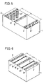
- Describing the intermittent carrying type in detail, in a plating equipment of soluble electrode type as shown in Fig. 5, 1 represents a plating tank, 5 a printed board (object to be plated) supported by a
carrying rod power feeding hangers anode 21′ comprises a mesh-like cylinder accommodating balls, chips, etc. of copper or copper alloy. - In such plating apparatus, however, troublesome procedure is required for maintenance and control of copper ion concentration in the plating solution because the anode (such as copper ball) 21′ is soluble, and much labor and time are required for supply and replacement of the anode itself. Further, in order to prevent non-uniformity of the plating film thickness caused by the change of interpolar distance due to wearing of anode, the interpolar distance ℓ must be increased. This involves such problems as the large-size equipment or the increase of initial make-up of electrolytic bath.
- To solve the above problems, it has been proposed to use insoluble anode and to supply copper ions, generated in a separate copper dissolving tank, to the plating tank. However, in case of such insoluble anode, equilibrium potential is increased compared with a soluble anode, and this enhances oxidizing decomposition of the additives (such as polyether, organic sulfur compound, etc.) by positive polarization. As the result, the consumption of the additives is increased, and this in turn raises the cost of electroplating, resulting in the problems caused by the introduction of insoluble anode.
- To ensure stable long-term use of additive by preventing the decomposition of the additives and to facilitate the plating solution control, a method to separate the anode (21) from the object to be plated (5) by a diaphragm has been proposed (e.g. Japanese Provisional Patent Publication No. 297884/1989) .
- Specifically, as shown in Fig. 6, insoluble plate electrode is used as
anode 21, and adiaphragm 31 is provided between theanode 21 and the object to be plated 5. In such insoluble electrode system, most of the plating solution containing the additive is not brought into direct contact with theanode 21, and this prevents the decomposition of the additive and minimizes the use of expensive reagents. - However, even in this insoluble electrode system, the
diaphragm 31 is easily deformed or broken, and it is difficult to inspect and replace thediaphragm 31. The present applicant previously proposed an integrated type apparatus as shown in Fig. 4, in which aninsoluble electrode 21 and adiaphragm 31 are placed in a liquid-tightmain unit case 11 and thediaphragm 31 is covered by rib member 41 (Japanese Patent Application No. 215636/1990) . In Fig. 4, 15 represents a spacer, and S denotes an accommodation space, i.e. closed space, for theelectrode 21. By such arrangement, thediaphragm 31 can be protected perfectly, and inspection can be rapidly and easily performed. Also, uniform current distribution can be assured by the separation effect of theupright planes 42a formed by a plurality ofgrids 42. - In the batch processing system by intermittent carrying type, it is apparently advantageous for the improvement of productivity and compact design of the equipment to provide a continuous processing system, in which
soluble anodes 21′ are arranged above and below of a plating tank 1 as shown in Fig. 5 orinsoluble anodes 21 anddiaphragms 31 are furnished above and below in the plating tank 1 as shown in Fig. 6, and the object to be plated 5 is carried horizontally by a conveyor through the space between them. - However, the continuous processing system of horizontal carrying type is not widely used at present.
- The reasons for this may be as follows ; In case the
soluble anodes 21′ are furnished above and below as shown in Fig. 5, non-uniformity of plating film thickness caused by the change of interpolar distance due to wearing of anode as explained in the above batch processing becomes more conspicuous and the replacement of the anode itself is also difficult. On the other hand, in case theinsoluble anodes 21 are furnished above and below as shown in Fig. 6, the inspection and replacement of thediaphragms 31 become more complicated and difficult. - In this respect, the present applicant bas studied and produced a continuous processing system on trial by adopting the above integrated type diapbragm electrode structure (11, 21, 31 and 41) as proposed previously (Japanese Patent Application No. 215636/1990) . Although perfect protection can be provided for the
diaphragm 31 and the inspection and replacement of thediaphragm 31 are done easier in this system, new problems have risen such as wide variation of plating film thickness due to the stagnation of the gas generated frominsoluble anode 21 in the closed space S formed bymain unit case 11 anddiaphragm 31, and the difficulty for feeding electric current smoothly. Particularly, in case of copper plating on plate type printed board having through-hole, the proposed system cannot be used practically. - To eliminate the above problems, the object of the present invention is to offer a horizontal carrying type electroplating apparatus making it possible to produce uniform plating film smoothly and efficiently with high productivity by introducing insoluble electrode structure with perfect degassing.
- The horizontal carrying type electroplating apparatus according to the present invention comprises an upper electrode and a lower electrode placed face-to-face in a plating tank and for performing electroplating by carrying the plate type objects to be plated in horizontal direction between two electrodes, characterized in that said upper electrode and said lower electrode are placed face-to-face and covered with a diaphragm to form a closed space where insoluble plate electrode is furnished in diaphragm electrode structure, a plurality of small holes penetrating both sides of insoluble plate electrode are provided on the diaphragm electrode structure of the upper electrode, degassing holes are furnished on upper portion of said closed space, the diaphragm of diaphragm electrode structure of the lower electrode is installed obliquely on the bottom surface of a plating tank, and degassing holes are provided on the higher side of the diaphragm in the closed space.
- According to the present invention with the above arrangement, plating film can be formed efficiently on upper and lower surfaces of the objects to be plated when the plate type objects are carried horizontally between upper and lower electrodes of the diaphragm electrode structure.
- In this case, the gas generated from lower surface of the upper electrode passes through small holes on the insoluble plate electrode, and it is moved toward the upper surface and is discharged out of the diaphragm electrode structure through the degassing holes. At the same time, the gas generated from upper surface of the lower electrode moves upward along the inclined surface of the diaphragm and is discharged out of the diaphragm electrode structure through the degassing hole on the higher side.
- Accordingly, gas is not stagnated between each of the insoluble plate electrodes and the objects to be plated. This ensures smooth current flow and uniform and high quality plating with high efficiency on both sides of the objects to be plated.
- Moreover, because upper and lower electrodes are designed in integrated diaphragm electrode structure, there is no need to use expensive additives, and the inspection of diaphragm can be easily and quickly performed.
- Specifically, the apparatus according to the present invention has such structure that upper electrode and lower electrode are assembled integrally with insoluble plate electrodes and diaphragm, etc., that small holes are provided on the upper electrode, and that the diaphragm is installed obliquely on lower electrode to provide degassing means. Accordingly, the apparatus has such advantages as shorter interpolar distance between two electrodes, compact size of the apparatus, saving of expensive additives, etc., and uniform and high quality plating can be accomplished by simply carrying the objects to be plated in horizontal direction, and the productivity can be extensively increased. Further, the inspection of diaphragm can be rapidly and easily achieved, and perfect protection can be provided for the diaphragm. Thus, a horizontal carrying type electroplating apparatus suitable for practical use can be offered.
-
- Fig. 1 is a cross-sectional view of an embodiment of the present invention;
- Fig. 2 is a front view along the line II - II of Fig. 1 :
- Fig. 3 is a partial enlarged cross-sectional view of an insoluble upper electrode;
- Fig. 4 is a perspective view for explaining basic configuration of an integral type insoluble diaphragm electrode structure; and
- Fig. 5 and Fig. 6 are the drawings of electroplating apparatus of conventional batch processing type. Fig. 5 shows the case with soluble electrodes, and Fig. 6 the case with insoluble electrodes.
- In the figures, 1 represents a plating tank, 5 an object to be plated, 11 a main unit case, 12 degassing holes, 13 a short pipe, 15 spacers, 16 degassing holes, 21 insoluble plate electrodes (upper and lower electrodes) , 22 small holes, 31 a diaphragm, 41 rib member, 42 grid, and 100 supporting members of horizontal carrying means.
- In the following, an embodiment of the present invention is described in connection with the drawings.
- As shown in Fig. 1 and Fig. 2, the present electroplating apparatus comprises an upper electrode and a lower electrode placed face-to-face in a plating tank 1, and the object to be plated 5 of plate shape (printed board having through-hole in the present embodiment) are carried horizontally in the direction X in Fig. 1 between these electrodes by supporting them by the supporting
members - The diaphragm electrode structure as referred here is in such arrangement that insoluble plate electrode (anode) 21 is placed in a closed space S covered by a
diaphragm 31 as shown in Fig. 1. In amain unit case 11, aninsoluble plate electrode 21 and adiaphragm 31 are fixed integrally by bolts, while maintaining a certain gap between them throughspacers 15, and aninsoluble plate electrode 21 is accommodated in the closed space S. Therefore, most of the plating solution containing the additive is not brought into direct contact with the insoluble plate electrode (anode) 21, and the decomposition of the additive can be prevented. At the same time, theanode 21 and thediaphragm 31 can be taken out integrally out of the plating tank 1, and this ensures easy and rapid inspection. - Further, the
diaphragm 31 is basically covered byrib member 41 as shown in Fig. 4 from outside. This protects thediaphragm 31 from deformation and damage, and uniform current distribution is assured by the upright surfaces (42a) of the grid (42) . Because the entire mechanical strength can be reinforced by the rigidity ofmain unit case 11 and therib member 41, theanode 21 itself can be designed in thinner and economical size. - As shown in Fig. 1 and Fig. 3, the diaphragm electrode structure of upper electrode is provided with a plurality of
small holes 22 penetrating through both sides of theanode 21, and degassingholes 12 are furnished on upper side of the closed space S. In the present embodiment, thedegassing holes 12 are guided out of the plating solution throughshort pipes 13. - Therefore, the gas generated from the lower surface of the
anode 21, i.e. from the side facing the objects to be plated 5, passes through thesmall holes 22 and it is discharged outside through thedegassing holes 12. In this case, therecesses 25 near thesmall holes 22 as shown in Fig. 3 are provided on the lower surface of theanode 21, and this enhances gas collecting effect to ensure smooth degassing. Because the gas is not stagnated within the closed space S, smooth and uniform plating can be accomplished on upper surface and through-hole of the objects to be plated 5. - On the other hand, in the diaphragm electrode structure of the lower electrode, the
spacers 15 are furnished with difference in height so that thediaphragm 31 can be inclined with ascending slope toward the carrying direction X of the object to be plated 5 relative to the bottom surface of the plating tank 1 as shown in Fig. 1. Also, degassingholes 16 are furnished downstream of the closed space S (the right side in Fig. 1) , and it is guided toward outside by anexhaust pipe 17. Accordingly, the gas generated from upper surface of theanode 21 goes upward along the inner surface of thediaphragm 31 in the closed space S and is discharged outward through thedegassing hole 16. Because gas is not stagnated within the closed space S, smooth and uniform plating can be accomplished on lower surface and through-hole of the object to be plated 5. - In an electroplating apparatus with such arrangement, uniform and high quality plating can be continuously accomplished on upper and lower surfaces of the object to be plated 5 when the object of
planar shape 5 is horizontally carried between upper and lower electrodes (21 and 21) . - According to the present embodiment, upper electrode and lower electrode are formed in integral diaphragm electrode structure, and degassing means (22 and 12) (31′ and 16) are provided on these two diaphragm electrode structures. Thus, when the object to be plated 5 is horizontally carried through between these two electrodes, high quality plating can be accomplished efficiently and smoothly with high productivity, while enjoying all of the advantages such as compact design achieved by the adoption of insoluble electrode (anode) , the prevention of decomposition of additive, etc.
- Each of the diaphragm electrode structures consists of integrated assembly of
main unit case 11,insoluble plate electrode 21,diaphragm 31 andrib member 41, and this contributes to perfect protection of thediaphragm 31 and quick and easy inspection of thediaphragm 31. The apparatus is in compact and lightweight design, and this assures rapid propagation of this horizontal carrying type electroplating apparatus. - Because the entire diaphragm electrode structure is in simple, compact and lightweight design, it is easy to carry it in or out and can be easily installed and fixed in the plating tank 1. Because the space S is small, the initial decomposition of the additive can be minimized, and this ensures economic features of the apparatus.
- Each of the
components insoluble electrode 21 and thediaphragm 31 can be achieved quickly and easily. Because the entire apparatus can be carried away by a single person, higher efficiency in transportation is assured. - Degassing effect can be perfectly provided by furnishing adequate number of
small holes 22 on theinsoluble anode 21 in case of the upper electrode, and by providing adequate inclination angle of thediaphragm 31 in case of the lower electrode. This means easy adjustment to the size of the object to be plated 5 and to its carrying speed, and wide range of adaptability is thus assured. Moreover, simple construction ensures stable degassing, and this contributes to the production of uniform and high quality plating film. - Further, because
rib member 41 is designed in grid pattern, the mechanical strength of the entire insoluble electrode structure can be increased. This leads to lightweight and thin design of theinsoluble electrode 21 itself and to the reduction of cost. - Each of the grids (42) of rib member (41) has upright surface (42a) perpendicular to the object to be plated 5, and unnecessary flow of the current can be prevented and uniform plating film can be produced.
- Further, because the
insoluble electrode 21 is formed in plate shape and its size can be freely selected, it is suitable particularly for uniform plating on large-size printed board.
Claims (10)
- A horizontal carrying type electroplating apparatus, comprising an upper electrode and a lower electrode placed face-to-face in a plating tank, whereby plating may be performed by passing the object to be plated between the two electrodes, characterised in that:
the electrodes are insoluble plate electrodes and each of the opposing faces of the two face-to-face electrodes are covered by a respective diaphragm;
each electrode and each adjacent diaphragm is mounted within a supporting structure, thereby providing upper and lower diaphragm/electrode structures;
the upper electrode is penetrated by a plurality of small holes and the upper portion of the upper diaphragm/electrode structure is provided with a first degassing means; and
the diaphragm of the lower diaphragm/electrode structure is positioned in relation to the face of the lower electrode so that part of the diaphragm is spaced to a greater extent than the remainder of the diaphragm, and that portion of the lower diaphragm/electrode structure beneath the said part being provided with a second degassing means. - A horizontal carrying type electroplating apparatus, comprising an upper electrode and a lower electrode placed face-to-face in a plating tank, whereby plating may be performed by passing the object to be plated between the two electrodes, characterised in that:
the electrodes are insoluble plate electrodes and each of the opposing faces of the two face-to-face electrodes are covered by a respective diaphragm;
each electrode and each adjacent diaphragm is mounted within a supporting structure, thereby providing upper and lower diaphragm/electrode structures;
the upper electrode is penetrated by a plurality of small holes and the upper portion of the upper diaphragm/electrode structure is provided with a first degassing means; and
the diaphragm of the lower diaphragm/electrode structure is obliquely positioned in relation to the lower electrode, and the end of the lower diaphragm/electrode structure having the highest diaphragm end in relation to the lower electrode is provided with a second degassing means. - An apparatus as claimed in claims 1 or 2, wherein the first degassing means comprises at least one hole in the upper side of the upper diaphragm electrode structure.
- An apparatus as claimed in claim 3, wherein the first degassing means further comprises at least one pipe in association with the at least one hole.
- An apparatus as claimed in claims 1, 2, 3 or 4, wherein the second degassing means comprises a plurality of recesses on the upper surface of the diaphragm of the lower diaphragm/electrodes structure.
- An apparatus as claimed in claims 1, 2, 3, 4 or 5 wherein at least one of the diaphragm/electrode structures further comprises at least one spacer for separating the diaphragm from the electrodes by a predetermined distance.
- An apparatus as claimed in claims 1, 2, 3, 4 or 5, wherein the lower diaphragm electrode structure further comprises a plurality of spacers, each of different height, for positioning the lower diaphragm at an angle in relation to the lower electrode.
- An apparatus as claimed in any one of the preceding claims, wherein the face of the supporting structure covering the diaphragm is provided with a grid pattern
- An apparatus as claimed in claim 8, wherein the grid pattern has upright surfaces positioned perpendicularly to the object to be plated.
- An apparatus as claimed in any one of the preceding claims, wherein the plurality of holes in the upper electrode is associated with a plurality of recesses on the lower surface of the said electrode.
Applications Claiming Priority (2)
| Application Number | Priority Date | Filing Date | Title |
|---|---|---|---|
| JP2215638A JPH086198B2 (en) | 1990-08-15 | 1990-08-15 | Horizontal transfer type plating equipment |
| JP215638/90 | 1990-08-15 |
Publications (2)
| Publication Number | Publication Date |
|---|---|
| EP0471577A1 true EP0471577A1 (en) | 1992-02-19 |
| EP0471577B1 EP0471577B1 (en) | 1995-10-11 |
Family
ID=16675721
Family Applications (1)
| Application Number | Title | Priority Date | Filing Date |
|---|---|---|---|
| EP91307532A Expired - Lifetime EP0471577B1 (en) | 1990-08-15 | 1991-08-15 | Horizontal carrying type electroplating apparatus |
Country Status (4)
| Country | Link |
|---|---|
| US (1) | US5102521A (en) |
| EP (1) | EP0471577B1 (en) |
| JP (1) | JPH086198B2 (en) |
| DE (1) | DE69113723T2 (en) |
Cited By (7)
| Publication number | Priority date | Publication date | Assignee | Title |
|---|---|---|---|---|
| EP0608616A1 (en) * | 1992-12-07 | 1994-08-03 | Ebara-Udylite Co, Ltd. | Electroplating apparatus |
| EP1029954A1 (en) * | 1998-09-08 | 2000-08-23 | Ebara Corporation | Substrate plating device |
| WO2004059045A2 (en) | 2002-12-23 | 2004-07-15 | METAKEM Gesellschaft für Schichtchemie der Metalle mbH | Anode used for electroplating |
| EP1712660A1 (en) | 2005-04-12 | 2006-10-18 | Enthone Inc. | Insoluble anode |
| US7578947B2 (en) | 2005-10-28 | 2009-08-25 | Enthone Inc. | Method for etching non-conductive substrate surfaces |
| US9005409B2 (en) | 2011-04-14 | 2015-04-14 | Tel Nexx, Inc. | Electro chemical deposition and replenishment apparatus |
| US9017528B2 (en) | 2011-04-14 | 2015-04-28 | Tel Nexx, Inc. | Electro chemical deposition and replenishment apparatus |
Families Citing this family (12)
| Publication number | Priority date | Publication date | Assignee | Title |
|---|---|---|---|---|
| US5980711A (en) * | 1996-06-10 | 1999-11-09 | Honda Giken Kogyo Kabushiki Kaisha | Electrolytic test machine |
| EP0959153A3 (en) | 1998-05-20 | 2000-09-13 | Process Automation International Limited | An electroplating machine |
| US6261425B1 (en) | 1998-08-28 | 2001-07-17 | Process Automation International, Ltd. | Electroplating machine |
| US6113759A (en) * | 1998-12-18 | 2000-09-05 | International Business Machines Corporation | Anode design for semiconductor deposition having novel electrical contact assembly |
| WO2003092891A1 (en) * | 2002-05-02 | 2003-11-13 | Mykrolis Corporation | Device and method for increasing mass transport at liquid-solid diffusion boundary layer |
| DE10248556B4 (en) * | 2002-10-18 | 2015-07-09 | Volkswagen Ag | Process for the treatment of a substrate for the purpose of corrosion protection and apparatus for degassing the liquid process medium used in the process |
| US8177945B2 (en) | 2007-01-26 | 2012-05-15 | International Business Machines Corporation | Multi-anode system for uniform plating of alloys |
| JP6129497B2 (en) * | 2011-09-29 | 2017-05-17 | アルメックスPe株式会社 | Continuous plating equipment |
| JP5805055B2 (en) * | 2012-11-24 | 2015-11-04 | 丸仲工業株式会社 | Horizontal conveyance type electroplating equipment |
| US9303329B2 (en) | 2013-11-11 | 2016-04-05 | Tel Nexx, Inc. | Electrochemical deposition apparatus with remote catholyte fluid management |
| JP7016995B1 (en) * | 2021-06-17 | 2022-02-07 | 株式会社荏原製作所 | Plating equipment and plating method |
| CN115094500B (en) * | 2022-06-16 | 2024-01-23 | 昆山沪利微电有限公司 | Device and method for horizontally electroplating copper |
Citations (2)
| Publication number | Priority date | Publication date | Assignee | Title |
|---|---|---|---|---|
| US4469564A (en) * | 1982-08-11 | 1984-09-04 | At&T Bell Laboratories | Copper electroplating process |
| US4871435A (en) * | 1988-10-14 | 1989-10-03 | Charles Denofrio | Electroplating apparatus |
Family Cites Families (2)
| Publication number | Priority date | Publication date | Assignee | Title |
|---|---|---|---|---|
| EP0276725B1 (en) * | 1987-01-26 | 1991-09-04 | Siemens Aktiengesellschaft | Apparatus for electroplating plate-like work pieces, particularly circuit boards |
| JPH0679922B2 (en) * | 1988-09-30 | 1994-10-12 | 松下冷機株式会社 | Kitchen storage |
-
1990
- 1990-08-15 JP JP2215638A patent/JPH086198B2/en not_active Expired - Lifetime
-
1991
- 1991-08-05 US US07/740,509 patent/US5102521A/en not_active Expired - Lifetime
- 1991-08-15 DE DE69113723T patent/DE69113723T2/en not_active Expired - Fee Related
- 1991-08-15 EP EP91307532A patent/EP0471577B1/en not_active Expired - Lifetime
Patent Citations (2)
| Publication number | Priority date | Publication date | Assignee | Title |
|---|---|---|---|---|
| US4469564A (en) * | 1982-08-11 | 1984-09-04 | At&T Bell Laboratories | Copper electroplating process |
| US4871435A (en) * | 1988-10-14 | 1989-10-03 | Charles Denofrio | Electroplating apparatus |
Non-Patent Citations (1)
| Title |
|---|
| PATENT ABSTRACTS OF JAPAN, vol. 8, no. 11, (C-205)[1448], 18th January 1984; & JP-A-58 177 487 (SUMITOMO KINZOKU KOGYO) 18-10-1983 * |
Cited By (14)
| Publication number | Priority date | Publication date | Assignee | Title |
|---|---|---|---|---|
| US5441619A (en) * | 1992-12-07 | 1995-08-15 | Ebara-Udylite Co., Ltd. | Electroplating apparatus |
| EP0608616A1 (en) * | 1992-12-07 | 1994-08-03 | Ebara-Udylite Co, Ltd. | Electroplating apparatus |
| EP1029954A1 (en) * | 1998-09-08 | 2000-08-23 | Ebara Corporation | Substrate plating device |
| EP1029954A4 (en) * | 1998-09-08 | 2006-07-12 | Ebara Corp | Substrate plating device |
| CN101027432B (en) * | 2002-12-23 | 2010-09-29 | 米塔凯姆金属涂层化学有限责任公司 | Anode used for electroplating |
| WO2004059045A2 (en) | 2002-12-23 | 2004-07-15 | METAKEM Gesellschaft für Schichtchemie der Metalle mbH | Anode used for electroplating |
| WO2004059045A3 (en) * | 2002-12-23 | 2005-02-24 | Metakem Ges Fuer Schichtchemie | Anode used for electroplating |
| US7943032B2 (en) | 2002-12-23 | 2011-05-17 | Metakem Gesellschaft Fur Schichtchemie Der Metalle Mbh | Anode used for electroplating |
| EP1712660A1 (en) | 2005-04-12 | 2006-10-18 | Enthone Inc. | Insoluble anode |
| CN1847466B (en) * | 2005-04-12 | 2010-09-08 | 恩通公司 | Insoluble anode |
| US7666283B2 (en) | 2005-04-12 | 2010-02-23 | Enthone Inc. | Insoluble anode |
| US7578947B2 (en) | 2005-10-28 | 2009-08-25 | Enthone Inc. | Method for etching non-conductive substrate surfaces |
| US9005409B2 (en) | 2011-04-14 | 2015-04-14 | Tel Nexx, Inc. | Electro chemical deposition and replenishment apparatus |
| US9017528B2 (en) | 2011-04-14 | 2015-04-28 | Tel Nexx, Inc. | Electro chemical deposition and replenishment apparatus |
Also Published As
| Publication number | Publication date |
|---|---|
| JPH0499897A (en) | 1992-03-31 |
| DE69113723T2 (en) | 1996-04-04 |
| US5102521A (en) | 1992-04-07 |
| DE69113723D1 (en) | 1995-11-16 |
| JPH086198B2 (en) | 1996-01-24 |
| EP0471577B1 (en) | 1995-10-11 |
Similar Documents
| Publication | Publication Date | Title |
|---|---|---|
| EP0471577B1 (en) | Horizontal carrying type electroplating apparatus | |
| CA1068641A (en) | Method and apparatus for the electrodeposition of metal | |
| US6398939B1 (en) | Method and apparatus for controlling flow in an electrodeposition process | |
| CN100582317C (en) | Device and method for electrolytically treating an at least superficially electrically conducting work piece | |
| JPH09505639A (en) | Equipment for processing printed circuit boards | |
| KR890002839B1 (en) | Process of continuously electrodepositing on strip metal on one or both sides | |
| EP1438446B1 (en) | System and method for electrolytic plating | |
| US3928152A (en) | Method for the electrolytic recovery of metal employing improved electrolyte convection | |
| JP3352081B2 (en) | Printed circuit board copper plating equipment | |
| RU2001127744A (en) | ELECTROLYZERS FOR ELECTROLYTIC PRODUCTION OF ALUMINUM WITH ANODES OXIDATING OXYGEN | |
| CN217378068U (en) | Electroplating equipment | |
| EP0420640B1 (en) | Process for electroplating and apparatus therefor | |
| ES553221A0 (en) | VERTICAL ELECTROLYTIC ZINC CUBA FOR STEEL STRIP ENLARGEMENT | |
| CN111020652B (en) | Jet-flow type electrochemical deposition equipment | |
| KR100426159B1 (en) | Electrodeposition method of metal film and apparatus therefor | |
| JPH08376Y2 (en) | Plating equipment using insoluble anode | |
| GB1335221A (en) | Support assemblies for electrolytic deposition on contact elements | |
| GB2041409A (en) | Processes for the symmetrisation of the vertical component of the magnetic field of electrolysis tanks | |
| US5897756A (en) | Device for chemical or electroyltic surface treatment of plate-like objects | |
| TWI706060B (en) | Electrolytic treatment component and surface treatment device using the same | |
| US20050077185A1 (en) | Conveyorized plating line and method for electrolytically metal plating a workpiece | |
| KR20070095856A (en) | Electroplating plating-form fixation electric current dispersion method | |
| JP2813530B2 (en) | Vertical jet electrolyzer | |
| SU697290A1 (en) | Electro-chemical deburring unit | |
| JPH05320989A (en) | Electrolyzer |
Legal Events
| Date | Code | Title | Description |
|---|---|---|---|
| PUAI | Public reference made under article 153(3) epc to a published international application that has entered the european phase |
Free format text: ORIGINAL CODE: 0009012 |
|
| AK | Designated contracting states |
Kind code of ref document: A1 Designated state(s): DE FR GB |
|
| 17P | Request for examination filed |
Effective date: 19920408 |
|
| 17Q | First examination report despatched |
Effective date: 19931112 |
|
| GRAA | (expected) grant |
Free format text: ORIGINAL CODE: 0009210 |
|
| AK | Designated contracting states |
Kind code of ref document: B1 Designated state(s): DE FR GB |
|
| REF | Corresponds to: |
Ref document number: 69113723 Country of ref document: DE Date of ref document: 19951116 |
|
| ET | Fr: translation filed | ||
| PLBE | No opposition filed within time limit |
Free format text: ORIGINAL CODE: 0009261 |
|
| STAA | Information on the status of an ep patent application or granted ep patent |
Free format text: STATUS: NO OPPOSITION FILED WITHIN TIME LIMIT |
|
| 26N | No opposition filed | ||
| REG | Reference to a national code |
Ref country code: GB Ref legal event code: IF02 |
|
| PGFP | Annual fee paid to national office [announced via postgrant information from national office to epo] |
Ref country code: DE Payment date: 20080829 Year of fee payment: 18 |
|
| PGFP | Annual fee paid to national office [announced via postgrant information from national office to epo] |
Ref country code: FR Payment date: 20080818 Year of fee payment: 18 |
|
| PGFP | Annual fee paid to national office [announced via postgrant information from national office to epo] |
Ref country code: GB Payment date: 20080827 Year of fee payment: 18 |
|
| GBPC | Gb: european patent ceased through non-payment of renewal fee |
Effective date: 20090815 |
|
| REG | Reference to a national code |
Ref country code: FR Ref legal event code: ST Effective date: 20100430 |
|
| PG25 | Lapsed in a contracting state [announced via postgrant information from national office to epo] |
Ref country code: FR Free format text: LAPSE BECAUSE OF NON-PAYMENT OF DUE FEES Effective date: 20090831 Ref country code: DE Free format text: LAPSE BECAUSE OF NON-PAYMENT OF DUE FEES Effective date: 20100302 |
|
| PG25 | Lapsed in a contracting state [announced via postgrant information from national office to epo] |
Ref country code: GB Free format text: LAPSE BECAUSE OF NON-PAYMENT OF DUE FEES Effective date: 20090815 |