EP0472475A2 - Bicondylar knee prosthesis - Google Patents
Bicondylar knee prosthesis Download PDFInfo
- Publication number
- EP0472475A2 EP0472475A2 EP91420221A EP91420221A EP0472475A2 EP 0472475 A2 EP0472475 A2 EP 0472475A2 EP 91420221 A EP91420221 A EP 91420221A EP 91420221 A EP91420221 A EP 91420221A EP 0472475 A2 EP0472475 A2 EP 0472475A2
- Authority
- EP
- European Patent Office
- Prior art keywords
- tibial
- tibial plateau
- plateau
- intended
- axis
- Prior art date
- Legal status (The legal status is an assumption and is not a legal conclusion. Google has not performed a legal analysis and makes no representation as to the accuracy of the status listed.)
- Withdrawn
Links
Images


Classifications
-
- A—HUMAN NECESSITIES
- A61—MEDICAL OR VETERINARY SCIENCE; HYGIENE
- A61F—FILTERS IMPLANTABLE INTO BLOOD VESSELS; PROSTHESES; DEVICES PROVIDING PATENCY TO, OR PREVENTING COLLAPSING OF, TUBULAR STRUCTURES OF THE BODY, e.g. STENTS; ORTHOPAEDIC, NURSING OR CONTRACEPTIVE DEVICES; FOMENTATION; TREATMENT OR PROTECTION OF EYES OR EARS; BANDAGES, DRESSINGS OR ABSORBENT PADS; FIRST-AID KITS
- A61F2/00—Filters implantable into blood vessels; Prostheses, i.e. artificial substitutes or replacements for parts of the body; Appliances for connecting them with the body; Devices providing patency to, or preventing collapsing of, tubular structures of the body, e.g. stents
- A61F2/02—Prostheses implantable into the body
- A61F2/30—Joints
- A61F2/38—Joints for elbows or knees
- A61F2/3836—Special connection between upper and lower leg, e.g. constrained
- A61F2/384—Special connection between upper and lower leg, e.g. constrained hinged, i.e. with transverse axle restricting the movement
- A61F2/385—Special connection between upper and lower leg, e.g. constrained hinged, i.e. with transverse axle restricting the movement also provided with condylar bearing surfaces
-
- A—HUMAN NECESSITIES
- A61—MEDICAL OR VETERINARY SCIENCE; HYGIENE
- A61F—FILTERS IMPLANTABLE INTO BLOOD VESSELS; PROSTHESES; DEVICES PROVIDING PATENCY TO, OR PREVENTING COLLAPSING OF, TUBULAR STRUCTURES OF THE BODY, e.g. STENTS; ORTHOPAEDIC, NURSING OR CONTRACEPTIVE DEVICES; FOMENTATION; TREATMENT OR PROTECTION OF EYES OR EARS; BANDAGES, DRESSINGS OR ABSORBENT PADS; FIRST-AID KITS
- A61F2/00—Filters implantable into blood vessels; Prostheses, i.e. artificial substitutes or replacements for parts of the body; Appliances for connecting them with the body; Devices providing patency to, or preventing collapsing of, tubular structures of the body, e.g. stents
- A61F2/02—Prostheses implantable into the body
- A61F2/30—Joints
- A61F2/38—Joints for elbows or knees
- A61F2/3868—Joints for elbows or knees with sliding tibial bearing
Definitions
- the present invention relates to a bicondylar knee prosthesis, that is to say a prosthesis comprising a femoral element reproducing the condyles of the femur and a tibial element reproducing the tibial plateau, each of these elements being integral, by its face opposite to that facing the other element, an anchor rod intended to be implanted, with or without cement, in the medullary canal of the corresponding bone.
- the femoral element and the tibial element are dissociated and, therefore, they have two degrees of freedom, namely the articular rotation and the internal and external rotations of the tibia, but they do not have no way to fight anteroposterior and lateral laxities.
- the tibial element is linked to the femoral element by an articulation axis which eliminates a degree of freedom since it prohibits internal and external rotations of the tibia.
- the rotation of the tibia around a transversely stationary axis does not allow to faithfully reproduce the joint of a healthy knee.
- a prosthesis of the aforementioned type consisting of four essential elements, namely a femoral element supporting a clevis for the articulation axis of this prosthesis, the cylindrical faces of the hubs of this clevis supposed to reproduce the condyles, a tibial element comprising a plate on which is fixed the support of the central hub of the joint, each of these two elements being provided with a fixing rod in the medullary canal of the corresponding bone and, finally , two intermediate plates that can be engaged on the support of the central hub secured to the tibial element and of which the upper one has two surfaces concaves in the form of cylinder segments and intended to serve as seats for the cylindrical external surfaces of the two hubs of the clevis secured to the femoral element.
- the intramedullary rod of the tibial element has a conical well and the lower intermediate plate is provided with a conical tail which can be engaged in the conical well of the intramedullary rod of the tibial element, this engagement retaining the rod of the lower intermediate plate freedom of rotation and axial movement to provide the patient with a possibility of rotation of the tibia around its axis and a possibility of significant flexion without premature blocking.
- This prosthesis therefore has the advantage, over those mentioned above, of eliminating all antero-posterior and lateral laxity, while allowing significant knee flexion. Furthermore, the freedom of rotation of the bearing of the articulation axis around an axis substantially perpendicular to the tibial plateau, that is to say substantially parallel to the axis of the intramedullary rod of the tibial element, allows internal and external rotation of the tibia.
- This prosthesis has the double disadvantage of not limiting the lateral laxity sufficiently and of essentially using the articulation axis and its hubs for the transmission of the forces which are known to be very important between the tibial and femoral elements of this prosthesis and which cause rapid wear of the articulation axis and its premature rupture which imposes on the patient a new operation for fitting a new prosthesis.
- the bearing of the hinge axis of the two elements is secured to a support linked to the tibial plateau by means allowing, on the one hand, its rotation around an axis substantially perpendicular to the face of this plate turned towards the femoral element and, on the other hand, the transverse movement of this articulation axis in a direction parallel to the aforementioned second axis is that is to say in a direction substantially perpendicular to the tibial plateau, the means of connection, to the tibial plateau, of the support of the articulation axis being constituted by a tail oriented radially to the axis of the bearing and engaged in a well, of cross section complementary to that of the aforementioned tail, arranged to receive it with the possibility of axial sliding, in the tibial plateau, on the one hand, the aforementioned tail and the well of the tibi
- the curvatures of the condyles and the trochlea of a natural knee do not have the same radius and the change in curvature which results therefrom normally limits the area of contact between the tibial plateau and the condyles.
- each groove of the tibial plateau has, at its end corresponding to the front of the knee, a rib of rounded cross section and of which at least a part of the vertex edge constitutes an arc of circle of the same radius and the same center as those of the bottom of the posterior part of this groove and, on the other hand, each condyle of the femoral element present, in the segment covered by the aforementioned rib of the corresponding groove in the tibial plateau, when the patient's leg is extended, a hollow of complementary shape capable of accommodating this rib in the aforementioned position of the patient's leg.
- the engagement of the ribs of the grooves of the tibial plateau in the hollows of the condyles also serves as a stop limiting the deployment of the leg.
- the intermediate plate and the bearing of the bearing of the articulation axis are made of an unalterable and biocompatible metal such as a titanium alloy optionally treated on the surface to receive an ion implantation while the tibial plate is made of a material.
- an unalterable and biocompatible metal such as a titanium alloy optionally treated on the surface to receive an ion implantation
- the tibial plate is made of a material.
- a synthetic material which is perfectly suitable for this use is high density polyethylene, possibly treated on the surface to receive an ion implantation.
- the means for rotary mounting and for guiding the tibial plateau on the intermediate plateau comprise, on the one hand, projecting from the face of the tibial plateau facing the intermediate plateau, a cylindrical sleeve surrounding its well intended to receive the tail of the support of the articulation axis and intended to be engaged in a through hole, provided in the intermediate plate to serve as a bearing and, on the other hand, projecting on the face of the intermediate plate facing the tibial plateau, a cylindrical ferrule coaxial with the through hole of the intermediate plateau and intended to be engaged in an annular groove, to receive it, in the underside of the tibial plateau, around the aforementioned cylindrical sleeve.
- the tibial plateau bears, on its underside, that is to say on its face facing the intermediate plateau, at least one projection in the form of a lug and the intermediate plate has, on its upper face opposite the tibial plate and in correspondence with each aforementioned projection, a mortise in an arc of a circle, capable of receiving this projection and of limiting the angular travel of the plate tibial by its ends, each of which serves as a stop for the projection of the tibial plateau.
- this bicondylar knee prosthesis is of the type comprising two elements, namely a tibial element 2 and a femoral element 3.
- the tibial element 2 is intended to replace the damaged tibial plateau of a tibia.
- this tibial element 2 comprises a tibial plate 21 secured, for example by assembly and screwing, of an anchoring rod 22 intended to be implanted, with or without cement, in the medullary canal of the tibia previously resected.
- the femoral element 3 essentially comprises two parallel ribs in the form of condyles 31 extending, forwardly, by a trochlear shield 32 intended to receive the anatomical patella or a prosthetic patella. Between the two condyles 31, the femoral element carries, on its upper face, that is to say that which faces away from the tibial plateau 21 of the tibial element 2, a hollowed out boss 33, intended to receive the anchor rod 34 to be used for fixing this femoral element 3 to the patient's previously resected femur.
- This anchor rod 34 is intended to be implanted, with or without cement, in the medular canal of the patient's femur.
- the axis of the rod 34 and, consequently, of the hollowed-out boss 33 is inclined by approximately 4 ° relative to the vertical median plane of the femoral element 3, which makes it possible to restore to this joint the physiological valgus.
- the prosthesis according to the invention is of the type comprising a hinge pin 4.
- the femoral element 3 has two coaxial bearings 35 (one of which is visible in FIG. 5) each of which is arranged in an intermediate piece 36 intended to serve as a spacer, as this will be explained below, after having been partially engaged in a hole 37 arranged to receive it, in a rib 38 provided on the rear face of each condyle 31 to which it serves as a stiffener.
- the axis 4 is therefore rigidly linked to the femoral part 3.
- connection of the articulation axis 4 to the tibial element is carried out by means of a support 23 in which is arranged a bearing 24 for the shaft 4 and which carries a radial tail 25 intended to be engaged, with the possibility of axial sliding, in a well 26 of the same cross section as it, arranged, to receive and guide it, in the tibial plateau 21.
- connection thus produced between the articulation axis 4 and the tibial element 2 therefore allows transverse displacements of the axis 4 parallel to the common axis 5 of the shank 25 and the well 26.
- this prosthesis with a second degree of freedom by allowing rotation of the tibial element 2, relative to the femoral element 3, about the axis 5 common to the tail 25 and to the well 26.
- the tibial plateau 21 is pivotally mounted, relative to the anchor rod 22 of the femoral element 2, around the common axis 5 of the tail 25 and the well 26 intended to receive it and there is provided, rigidly connected to the anchor rod 22, an intermediate plate 27 on which the tibial plate 21 is mounted with possibility of rotation about the axis 5.
- the tibial plateau 21 carries, projecting from its underside 21b, a cylindrical sleeve 21c surrounding its well intended to receive the tail 25 of the support 24 of the hinge pin 4, this sleeve being intended to be engaged in a through hole 27a m swam in the intermediate plate 27 to serve as its bearing and, on the other hand, the intermediate plate 27 carries, on its upper face facing the tibial plate 21, a cylindrical ferrule 27b coaxial with the through hole 27a and intended to be engaged in a annular groove 21d formed, to receive it, around the cylindrical sleeve 21c of the tibial plateau 21.
- the section transverse of the tail 25 and of the well 26 which no longer has to be of circular section has, advantageously, an oblong section as illustrated in FIG. 3.
- the intermediate plateau 27 carries, on its upper face facing the tibial plateau 21, two mortises 27c in the form of arcs of a circle centered on the axis 5 common to the tail 25, to the well 26 and to the through hole 27a while the tibial plateau 21 carries, projecting on its underside 21b, and in correspondence with each mortises 27c, two lugs 21f, also in the form of arcs of a circle, but representing a sector smaller than that of the mortises 27c, so as to allow a certain angular movement of the tibial plateau 21 relative to the intermediate plateau 27.
- This sleeve allows therefore to provide, without any difficulty, to this prosthesis, the possibilities of internal and external rotation of the tibia.
- This prosthesis therefore has two degrees of freedom since the axis 4 allows a first degree of freedom while the pivoting mounting of the tibial plateau 21 allows the second.
- the mounting of the axis 4 in its movable support 24 parallel to the axis 5 makes it possible to produce condyles 31 of non-circular profile, that is to say reproducing, as closely as possible, the profile of the natural condyles of a femur.
- FIG. 1 further shows that the presence of the intermediate parts 36, each of which is disposed between the support 23 of the hinge pin 4 and one of the ribs 38, has the effect of eliminating any lateral laxity of this prosthesis. Furthermore, the engagement of the tail 25 in the well 26 of the tibial plateau 21 itself axially linked to the intermediate plateau 27 eliminates any anteroposterior laxity.
- the tibial plateau 21 has, on its face 21a in contact with the condyles 31, two grooves 21e, each of which is intended to partially accommodate and guide one of the condyles 31 of the femoral element 3 .
- the ribs reproducing the condyles 31 and their extension reproducing the edges of the trochlea 32 of the femoral part 3 do not have the same radius.
- the segments of these two zones also meet in a transverse plane 39 visible in FIGS. 6, 7. Consequently, without any particular arrangement such as that described below, the arc of the sector of contact between the tibial plateau 21 and the associated condyle 31 is reduced to the arc of circle 40 as soon as the patient's leg bends a little since in the area bordering the trochlea 32, each rib is d 'a radius greater than that of its zone reproducing the condyles 31 and that it is the same for each bleeding 21st of the tibial plateau 21.
- each groove 21st of the tibial plateau 21 has, at its end corresponding to the front of the knee, that is to say at its end located on the right in FIG. 3, a rib 41 of rounded cross-section and each condyle or rib 31 reconstituting a present condyle, arranged astride the connection zone 42 between the arc of a circle reproducing the condyle and the curvature bordering the trochlea 32, a groove 43 of shape complementary to that of the aforementioned rib 41:
- each rib 41 constitutes, on a first section 41a originating opposite the front end of the groove 21e, an arc of a circle with the same radius and the same center as those at the bottom of the posterior part of the groove 21 in the extension of which this rib 41 arises while the forward extension of the knee, that is to say say towards the front end of the groove 21 of each rib 41, is rectilinear, that is to say constituted by a straight line 41b.
- Each recess 43 arranged in each condyle 31 occupies an internal position such that the rib 41 of the groove 21e associated with this condyle 31 is engaged in this recess 43 when the patient's leg is in extension as illustrated in FIG. 6.
- the intermediate plate 21 is made of high density polyethylene while all the other parts of this prosthesis, that is to say the intermediate plate 27 , the hinge pin 4, its support 24 and the tail 25 of the latter, as well as all of the femoral element 3, are made of titanium alloy such as that known in the trade under the reference TA6V.
- the latter whether they are made of high density polyethylene or of titanium alloy, have advantageously undergone ion implantation. All these materials used are naturally unalterable and biocompatible.
Abstract
Description
La présente invention concerne une prothèse bicondylienne du genou, c'est-à-dire une prothèse comportant un élément fémoral reproduisant les condyles du fémur et un élément tibial reproduisant le plateau tibial, chacun de ces éléments étant solidaire, par sa face opposée à celle tournée vers l'autre élément, d'une tige d'ancrage destinée à être implantée, avec ou sans ciment, dans le canal médullaire de l'os correspondant.The present invention relates to a bicondylar knee prosthesis, that is to say a prosthesis comprising a femoral element reproducing the condyles of the femur and a tibial element reproducing the tibial plateau, each of these elements being integral, by its face opposite to that facing the other element, an anchor rod intended to be implanted, with or without cement, in the medullary canal of the corresponding bone.
Il existe actuellement deux types de prothèses bicondyliennes. Dans les premières, dites à glissement, l'élément fémoral et l'élément tibial sont dissociés et, de ce fait, elles possèdent deux degrés de liberté, à savoir la rotation articulaire et les rotations interne et externe du tibia, mais elles ne possèdent aucun moyen de lutter contre les laxités antéro-postérieures et latérales.There are currently two types of bicondylar prostheses. In the first, called sliding, the femoral element and the tibial element are dissociated and, therefore, they have two degrees of freedom, namely the articular rotation and the internal and external rotations of the tibia, but they do not have no way to fight anteroposterior and lateral laxities.
Dans les secondes, dites à charnière, l'élément tibial est lié à l'élément fémoral par un axe d'articulation qui élimine un degré de liberté puisqu'il interdit les rotations interne et externe du tibia. En outre, la rotation du tibia autour d'un axe transversalement immobile ne permet pas de reproduire fidèlement l'articulation d'un genou sain.In the seconds, known as hinged, the tibial element is linked to the femoral element by an articulation axis which eliminates a degree of freedom since it prohibits internal and external rotations of the tibia. In addition, the rotation of the tibia around a transversely stationary axis does not allow to faithfully reproduce the joint of a healthy knee.
Par le brevet français 81 13723, on connait une prothèse du second type dans laquelle, pour permettre au plateau tibial de suivre le profil des condyles sans perte de contact avec le plateau tibial, le palier de l'axe d'articulation, solidaire du plateau tibial, est constitué par une lumière débouchant vers le haut. En outre, pour faire bénéficier cette prothèse d'un second degré de liberté et permettre ainsi les rotations interne et externe du tibia, des jeux mécaniques importants sont prévus entre l'axe et son palier, d'une part et entre le palier de l'axe et les paliers de la chape fémorale, d'autre part.By French patent 81 13723, a prosthesis of the second type is known in which, to allow the tibial plateau to follow the profile of the condyles without loss of contact with the tibial plateau, the bearing of the articulation axis, integral with the plateau tibial, is constituted by a light opening upwards. In addition, to make this prosthesis benefit from a second degree of freedom and thus allow internal and external rotations of the tibia, significant mechanical games are provided between the axis and its bearing, on the one hand and between the bearing of the axis and bearings of the femoral clevis, on the other hand.
Il en est résulté non seulement une grande laxité mais aussi une grande instabilité, très gênante pour la marche.This resulted not only in a great laxity but also in a great instability, very troublesome for walking.
Par le brevet US 4 301 553, on connaît une prothèse du type précité, constituée de quatre éléments essentiels, à savoir un élément fémoral supportant une chape pour l'axe d'articulation de cette prothèse, les faces cylindriques des moyeux de cette chape étant sensés reproduire les condyles, un élément tibial comportant un plateau sur lequel est fixé le support du moyeu central de l'articulation, chacun de ces deux éléments étant pourvu d'une tige de fixation dans le canal médullaire de l'os correspondant et, enfin, deux plateaux intermédiaires engageables sur le support du moyeu central solidaire de l'élément tibial et dont celui supérieur présente deux surfaces concaves en forme de segments de cylindre et destinées à servir de sièges aux surfaces extérieures cylindriques des deux moyeux de la chape solidaire de l'élément fémoral.From US Patent 4,301,553, a prosthesis of the aforementioned type is known, consisting of four essential elements, namely a femoral element supporting a clevis for the articulation axis of this prosthesis, the cylindrical faces of the hubs of this clevis supposed to reproduce the condyles, a tibial element comprising a plate on which is fixed the support of the central hub of the joint, each of these two elements being provided with a fixing rod in the medullary canal of the corresponding bone and, finally , two intermediate plates that can be engaged on the support of the central hub secured to the tibial element and of which the upper one has two surfaces concaves in the form of cylinder segments and intended to serve as seats for the cylindrical external surfaces of the two hubs of the clevis secured to the femoral element.
Dans cette prothèse, la tige intramédullaire de l'élément tibial présente un puits conique et le plateau intermédiaire inférieur est pourvu d'une queue conique engageable dans le puits conique de la tige intramédullaire de l'élément tibial, cet engagement conservant à la tige du plateau intermédiaire inférieur une liberté de rotation et de déplacement axial pour procurer au patient une possibilité de rotation du tibia autour de son axe et une possibilité de flexion importante sans blocage prématuré.In this prosthesis, the intramedullary rod of the tibial element has a conical well and the lower intermediate plate is provided with a conical tail which can be engaged in the conical well of the intramedullary rod of the tibial element, this engagement retaining the rod of the lower intermediate plate freedom of rotation and axial movement to provide the patient with a possibility of rotation of the tibia around its axis and a possibility of significant flexion without premature blocking.
Cette prothèse présente donc l'avantage, sur celles précitées, d'éliminer toute laxité-antéro-postérieure et latérale, tout en permettant une flexion importante du genou. En outre, la liberté de rotation du palier de l'axe d'articulation autour d'un axe sensiblement perpendiculaire au plateau tibial, c'est-à-dire sensiblement parallèle à l'axe de la tige intramédullaire de l'élément tibial, autorise les rotations interne et externe du tibia.This prosthesis therefore has the advantage, over those mentioned above, of eliminating all antero-posterior and lateral laxity, while allowing significant knee flexion. Furthermore, the freedom of rotation of the bearing of the articulation axis around an axis substantially perpendicular to the tibial plateau, that is to say substantially parallel to the axis of the intramedullary rod of the tibial element, allows internal and external rotation of the tibia.
Cette prothèse présente le double inconvénient de ne pas limiter suffisamment la laxité latérale et d'utiliser essentiellement l'axe d'articulation et ses moyeux pour la transmission des efforts que l'on sait très importants entre les éléments tibial et fémoral de cette prothèse et qui provoquent une usure rapide de l'axe d'articulation et sa rupture prématurée qui impose au patient une nouvelle opération pour pose d'une nouvelle prothèse.This prosthesis has the double disadvantage of not limiting the lateral laxity sufficiently and of essentially using the articulation axis and its hubs for the transmission of the forces which are known to be very important between the tibial and femoral elements of this prosthesis and which cause rapid wear of the articulation axis and its premature rupture which imposes on the patient a new operation for fitting a new prosthesis.
La présente invention vise à remédier à tous ces inconvénients. A cet effet, dans la prothèse qu'elle concerne et qui est du type à charnière, dont le palier de l'axe d'articulation des deux éléments est solidaire d'un support lié au plateau tibial par des moyens permettant, d'une part, sa rotation autour d'un axe sensiblement perpendiculaire à la face de ce plateau tournée vers l'élément fémoral et, d'autre part, le déplacement transversal de cet axe d'articulation dans une direction parallèle au second axe précité c'est-à-dire dans une direction sensiblement perpendiculaire au plateau tibial, les moyens de liaison, au plateau tibial, du support de l'axe d'articulation étant constitués par une queue orientée radialement à l'axe du palier et engagée dans un puits, de section transversale complémentaire de celle de la queue précitée, ménagé, pour la recevoir avec possibilité de coulissement axial, dans le plateau tibial, d'une part, la queue précitée et le puits du plateau tibial destiné à la recevoir présentent une section transversale non circulaire et, d'autre part, le plateau tibial présente, sur sa face en contact avec les condyles, deux saignées de forme complémentaire de celle du secteur embrassé des condyles et dont chacune est destinée à être engagée sur le secteur précité du condyle.The present invention aims to remedy all these drawbacks. To this end, in the prosthesis which it relates to and which is of the hinged type, the bearing of the hinge axis of the two elements is secured to a support linked to the tibial plateau by means allowing, on the one hand, its rotation around an axis substantially perpendicular to the face of this plate turned towards the femoral element and, on the other hand, the transverse movement of this articulation axis in a direction parallel to the aforementioned second axis is that is to say in a direction substantially perpendicular to the tibial plateau, the means of connection, to the tibial plateau, of the support of the articulation axis being constituted by a tail oriented radially to the axis of the bearing and engaged in a well, of cross section complementary to that of the aforementioned tail, arranged to receive it with the possibility of axial sliding, in the tibial plateau, on the one hand, the aforementioned tail and the well of the tibial plateau intended to receive it have a s non-circular cross section and, on the other hand, the tibial plateau has, on its face in contact with the condyles, two grooves of shape complementary to that of the embraced sector of the condyles and each of which is intended to be engaged on the aforementioned sector of the condyle.
Ces dispositions présentent non seulement l'avantage de réduire considérablement les risques de laxité latérale en assurant un meilleur guidage du plateau tibial sur les condyles du fémur, mais, surtout, celui de supprimer presque totalement les contraintes mécaniques entre l'axe d'articulation et ses moyeux et de conférer à cette prothèse une très grande longévité.These provisions not only have the advantage of considerably reducing the risks of lateral laxity by ensuring better guidance of the tibial plateau on the condyles of the femur, but, above all, that of almost completely eliminating the mechanical stresses between the axis of articulation and its hubs and give this prosthesis a very long life.
Comme on le sait, les courbures des condyles et de la trochlée d'un genou naturel n'ont pas le même rayon et le changement de courbure qui en résulte limite normalement le secteur de contact entre la plateau tibial et les condyles.As is known, the curvatures of the condyles and the trochlea of a natural knee do not have the same radius and the change in curvature which results therefrom normally limits the area of contact between the tibial plateau and the condyles.
Cette limitation qui est pratiquement sans importance dans un genou sain, équipé de ligaments en bon état présente, évidemment, l'inconvénient de nuire à la stabilité dans un genou équipé d'une prothèse et dont les ligaments sont au moins distendus sinon totalement détériorés.This limitation, which is practically unimportant in a healthy knee, equipped with ligaments in good condition, obviously has the disadvantage of impairing stability in a knee equipped with a prosthesis and whose ligaments are at least distended if not totally deteriorated.
C'est pourquoi, suivant une forme d'exécution préférée de l'invention, d'une part, chaque saignée du plateau tibial présente, à son extrémité correspondant à l'avant du genou, une nervure de section transversale arrondie et dont au moins une partie de l'arête du sommet constitue un arc de cercle de même rayon et de même centre que ceux du fond de la partie postérieure de cette saignée et, d'autre part, chaque condyle de l'élément fémoral présente, dans le segment recouvert par la nervure précitée de la saignée correspondante du plateau tibial, lorsque la jambe du patient est en extension, un creux de forme complémentaire apte à loger cette nervure dans la position précitée de la jambe du patient.This is why, according to a preferred embodiment of the invention, on the one hand, each groove of the tibial plateau has, at its end corresponding to the front of the knee, a rib of rounded cross section and of which at least a part of the vertex edge constitutes an arc of circle of the same radius and the same center as those of the bottom of the posterior part of this groove and, on the other hand, each condyle of the femoral element present, in the segment covered by the aforementioned rib of the corresponding groove in the tibial plateau, when the patient's leg is extended, a hollow of complementary shape capable of accommodating this rib in the aforementioned position of the patient's leg.
Grâce à cette disposition, le contact entre chaque condyle et le plateau tibial est réalisé sur un secteur d'arc de cercle bien plus important qu'en l'absence de ces dispositions, ce qui améliore considérablement la stabilité du genou.Thanks to this arrangement, the contact between each condyle and the tibial plateau is made over a much larger arc of a circle than in the absence of these arrangements, which considerably improves the stability of the knee.
En outre, l'engagement des nervures des saignées du plateau tibial dans les creux des condyles sert aussi de butée limitant le déploiement de la jambe.In addition, the engagement of the ribs of the grooves of the tibial plateau in the hollows of the condyles also serves as a stop limiting the deployment of the leg.
Enfin, l'augmentation de l'arc de cercle du secteur de contact entre les condyles de l'élément fémoral et les saignées du plateau tibial diminue les pressions unitaires, lors des transmissions d'efforts et, par conséquent, l'usure de ces éléments.Finally, the increase in the arc of a circle in the contact sector between the condyles of the femoral element and the grooves in the tibial plateau decreases the unit pressures, during the transmission of forces and, consequently, wear. of these elements.
Il faut aussi noter que l'engagement des condyles de l'élément fémoral dans les saignées du plateau tibial participe, avec la section non circulaire de la queue du support du moyeu de l'axe d'articulation lié au moyeu tibial, à la liaison en rotation du plateau tibial et de l'élément fémoral lors des rotations latérales gauche et droite du tibia, ce qui assure une meilleure répartition des efforts et diminue encore les causes d'une usure locale.It should also be noted that the engagement of the condyles of the femoral element in the grooves of the tibial plateau participates, with the non-circular section of the tail of the hub support of the articulation axis linked to the tibial hub, in the connection in rotation of the tibial plateau and of the femoral element during the left and right lateral rotations of the tibia, which ensures a better distribution of the forces and further reduces the causes of local wear.
De préférence, le plateau intermédiaire et le support du palier de l'axe d'articulation sont en un métal inaltérable et biocompatible tel qu'en alliage de titane éventuellement traité en surface pour recevoir une implantation ionique tandis que le plateau tibial est en une matière synthétique bio-compatible et présentant un faible coefficient de frottement par rapport au métal constitutif des pièces précitées. Une matière synthétique convenant parfaitement à cet usage est le polyéthylène haute densité, éventuellement traité en surface pour recevoir une implantation ionique.Preferably, the intermediate plate and the bearing of the bearing of the articulation axis are made of an unalterable and biocompatible metal such as a titanium alloy optionally treated on the surface to receive an ion implantation while the tibial plate is made of a material. synthetic bio-compatible and having a low coefficient of friction compared to the metal of the aforementioned parts. A synthetic material which is perfectly suitable for this use is high density polyethylene, possibly treated on the surface to receive an ion implantation.
Suivant une caractéristique simple de l'invention, les moyens de montage rotatif et de guidage du plateau tibial sur le plateau intermédiaire comprennent, d'une part, en saillie sur la face du plateau tibial tournée vers le plateau intermédiaire, un manchon cylindrique entourant son puits destiné à recevoir la queue du support de l'axe d'articulation et destiné à être engagé dans un trou traversant, prévu dans le plateau intermédiaire pour lui servir de palier et, d'autre part, en saillie sur la face du plateau intermédiaire tournée vers le plateau tibial, une virole cylindrique coaxiale au trou traversant du plateau intermédiaire et destinée à être engagée dans une gorge annulaire ménagée, pour la recevoir, dans la face inférieure du plateau tibial, autour du manchon cylindrique précité.According to a simple characteristic of the invention, the means for rotary mounting and for guiding the tibial plateau on the intermediate plateau comprise, on the one hand, projecting from the face of the tibial plateau facing the intermediate plateau, a cylindrical sleeve surrounding its well intended to receive the tail of the support of the articulation axis and intended to be engaged in a through hole, provided in the intermediate plate to serve as a bearing and, on the other hand, projecting on the face of the intermediate plate facing the tibial plateau, a cylindrical ferrule coaxial with the through hole of the intermediate plateau and intended to be engaged in an annular groove, to receive it, in the underside of the tibial plateau, around the aforementioned cylindrical sleeve.
Suivant encore une autre caractéristique de cette prothèse ayant pour but de limiter les rotations interne et externe du tibia, le plateau tibial porte, sur sa face inférieure, c'est-à-dire sur sa face tournée vers le plateau intermédiaire, au moins une saillie en forme d'ergot et le plateau intermédiaire présente, sur sa face supérieure en regard avec le plateau tibial et en correspondance de chaque saillie précitée, une mortaise en arc de cercle, apte à recevoir cette saillie et à limiter la course angulaire du plateau tibial par ses extrémités dont chacune sert de butée à la saillie du plateau tibial.According to yet another characteristic of this prosthesis, the aim of which is to limit the internal and external rotations of the tibia, the tibial plateau bears, on its underside, that is to say on its face facing the intermediate plateau, at least one projection in the form of a lug and the intermediate plate has, on its upper face opposite the tibial plate and in correspondence with each aforementioned projection, a mortise in an arc of a circle, capable of receiving this projection and of limiting the angular travel of the plate tibial by its ends, each of which serves as a stop for the projection of the tibial plateau.
De toute façon l'invention sera bien comprise à l'aide de la description qui suit en référence au dessin schématique annexé représentant, à titre d'exemple non limitatif, une forme d'exécution de cette prothèse :
- Figure 1 est une vue en perspective montrant les deux éléments de cette prothèse articulés l'un à l'autre ;
- Figure 2 est une vue de côté en élévation de la prothèse de figure 1 ;
- Figure 3 est une vue en perspective éclatée de l'élément tibial de la prothèse des figures 1 et 2 ;
- Figure 4 est une vue en perspective, par-dessous, du plateau tibial seul de l'élément tibial de figure 3 ;
- Figure 5 est une vue en perspective éclatée de l'élément fémoral des figures 1 et 2.
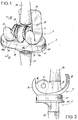
- Figure 6 est une vue partielle, en coupe suivant VI-VI de figure 1 montrant un agencement particulier des saignées et des condyles, la jambe du patient étant en extension ;
- Figure 7 est une vue similaire à figure 6 correspondant aux positions de la jambe du patient, respectivement totalement et partiellement fléchie ;
- Figure 8 est une vue en coupe VIII-VIII du figure 6.
- Figure 1 is a perspective view showing the two elements of this prosthesis hinged to each other;
- Figure 2 is a side elevational view of the prosthesis of Figure 1;
- Figure 3 is an exploded perspective view of the tibial element of the prosthesis of Figures 1 and 2;
- Figure 4 is a perspective view, from below, of the tibial plateau alone of the tibial element of Figure 3;
- Figure 5 is an exploded perspective view of the femoral element of Figures 1 and 2.
- Figure 6 is a partial view, in section along line VI-VI of Figure 1 showing a particular arrangement of the grooves and condyles, the patient's leg being extended;
- Figure 7 is a view similar to Figure 6 corresponding to the positions of the patient's leg, respectively fully and partially bent;
- Figure 8 is a sectional view VIII-VIII of Figure 6.
Comme le montre le dessin, cette prothèse bicondylienne du genou est du type comportant deux éléments, à savoir un élément tibial 2 et un élément fémoral 3. L'élément tibial 2 est destiné à remplacer le plateau tibial endommagé d'un tibia. A cet effet, cet élément tibial 2 comporte un plateau tibial 21 solidaire, par exemple par assemblage et vissage, d'une tige d'ancrage 22 destiné à être implantée, avec ou sans ciment, dans le canal médullaire du tibia préalablement réséqué.As the drawing shows, this bicondylar knee prosthesis is of the type comprising two elements, namely a
L'élément fémoral 3 comprend, essentiellement, deux nervures parallèles en forme de condyles 31 se prolongeant, vers l'avant, par un bouclier trochléen 32 destiné à recevoir la rotule anatomique ou une rotule prothétique. Entre les deux condyles 31, l'élément fémoral porte, sur sa face supérieure, c'est-à-dire celle tournée à l'opposé du plateau tibial 21 de l'élément tibial 2, un bossage évidé 33, destiné à recevoir la tige d'ancrage 34 devant servir à la fixation de cet élément fémoral 3 au fémur préalablement réséqué du patient. Cette tige d'ancrage 34 est destinée à être implantée, avec ou sans ciment, dans le canal médulaire du fémur du patient. L'axe de la tige 34 et, par conséquent, du bossage évidé 33, est incliné d'environ 4° par rapport au plan vertical médian de l'élément fémoral 3, ce qui permet de restituer à cette articulation le valgus physiologique.The
Comme indiqué précédemment, la prothèse selon l'invention est du type comportant un axe d'articulation 4.As indicated above, the prosthesis according to the invention is of the type comprising a
Pour permettre sa liaison à l'axe d'articulation 4, l'élément fémoral 3 présente deux paliers coaxiaux 35 (dont un est visible sur la figure 5) dont chacun est aménagé dans une pièce intermédiaire 36 destinée à servir d'entretoise, comme cela sera expliqué ci-après, après avoir été engagée, partiellement, dans un trou 37 aménagé, pour la recevoir, dans une nervure 38 prévue sur la face postérieure de chaque condyle 31 auquel elle sert de raidisseur. L'axe 4 se trouve donc lié rigidement à la pièce fémorale 3.To allow its connection to the
La liaison de l'axe d'articulation 4 à l'élément tibial est réalisée par l'intermédiaire d'un support 23 dans lequel est aménagé un palier 24 pour l'arbre 4 et qui porte une queue radiale 25 destinée à être engagée, avec possibilité de coulissement axial, dans un puits 26 de même section transversale qu'elle, aménagé, pour la recevoir et la guider, dans le plateau tibial 21.The connection of the
La liaison ainsi réalisée entre l'axe d'articulation 4 et l'élément tibial 2 autorise donc des déplacements transversaux de l'axe 4 parallèlement à l'axe commun 5 de la queue 25 et du puits 26.The connection thus produced between the
L'articulation de l'élément tibial 2 à l'élément fémoral 3 procure donc à cette prothèse un premier degré de liberté puisqu'autorisant un pivotement autour de l'axe 4.The articulation of the
Il est possible de procurer à cette prothèse un second degré de liberté en autorisant une rotation de l'élément tibial 2, par rapport à l'élément fémoral 3, autour de l'axe 5 commun à la queue 25 et au puits 26. A cet effet, dans le but de diminuer les causes d'usure du plateau tibial 21 par les condyles 31 de l'élément fémoral 3, le plateau tibial 21 est monté pivotant, par rapport à la tige d'ancrage 22 de l'élément fémoral 2, autour de l'axe commun 5 de la queue 25 et du puits 26 destiné à la recevoir et il est prévu, lié rigidement à la tige d'ancrage 22, un plateau intermédiaire 27 sur lequel le plateau tibial 21 est monté avec possibilité de rotation autour de l'axe 5. A cet effet, d'une part, le plateau tibial 21 porte, en saillie sur sa face inférieure 21b, un manchon cylindrique 21c entourant son puits destiné à recevoir la queue 25 du support 24 de l'axe d'articulation 4, ce manchon étant destiné à être engagé dans un trou traversant 27a ménagé dans le plateau intermédiaire 27 pour lui servir de palier et, d'autre part le plateau intermédiaire 27 porte, sur sa face supérieure tournée vers le plateau tibial 21, une virole cylindrique 27b coaxiale au trou traversant 27a et destinée à être engagée dans une gorge annulaire 21d ménagée, pour la recevoir, autour du manchon cylindrique 21c du plateau tibial 21. Dans ce cas, la section transversale de la queue 25 et du puits 26 qui n'a plus à être de section circulaire présente, avantageusement, une section oblongue comme illustré sur la figure 3.It is possible to provide this prosthesis with a second degree of freedom by allowing rotation of the
Pour limiter l'angle de pivotement du plateau tibial 21 sur le plateau intermédiaire 27 autour de l'axe 5, dans l'exemple illustré sur le dessin, le plateau intermédiaire 27 porte, sur sa face supérieure tournée vers le plateau tibial 21, deux mortaises 27c en forme d'arcs de cercle centrés sur l'axe 5 commun à la queue 25, au puits 26 et au trou traversant 27a tandis que le plateau tibial 21 porte, en saillie sur sa face inférieure 21b, et en correspondance de chacune des mortaises 27c, deux ergots 21f, également en forme d'arcs de cercle, mais représentant un secteur inférieur à celui des mortaises 27c, de manière à permettre un certain débattement angulaire du plateau tibial 21 par rapport au plateau intermédiaire 27. Ce manchon permet donc de procurer, sans aucune difficulté, à cette prothèse, les possibilités de rotations interne et externe du tibia.To limit the pivot angle of the
Cette prothèse présente donc bien deux degrés de liberté puisque l'axe 4 autorise un premier degré de liberté tandis que le montage pivotant du plateau tibial 21 autorise le second.This prosthesis therefore has two degrees of freedom since the
En outre, le montage de l'axe 4 dans son support 24 mobile parallèlement à l'axe 5 permet de réaliser des condyles 31 de profil non circulaire, c'est-à-dire reproduisant, au plus près, le profil des condyles naturels d'un fémur.In addition, the mounting of the
L'examen de la figure 1 montre, en outre, que la présence des pièces intermédiaires 36 dont chacune est disposée entre le support 23 de l'axe d'articulation 4 et l'une des nervures 38, a pour effet d'éliminer toute laxité latérale de cette prothèse. Par ailleurs, l'engagement de la queue 25 dans le puits 26 du plateau tibial 21 lui-même lié axialement au plateau intermédiaire 27 élimine toute laxité antéro-postérieure.Examination of FIG. 1 further shows that the presence of the
Pour améliorer encore la stabilité de cette prothèse, le plateau tibial 21 présente, sur sa face 21a en contact avec les condyles 31, deux saignées 21e dont chacune est destinée à loger partiellement et guider l'un des condyles 31 de l'élément fémoral 3.To further improve the stability of this prosthesis, the
Comme le montre la figure 6, les nervures reproduisant les condyles 31 et leur prolongement reproduisant les bords de la trochlée 32 de la pièce fémorale 3 n'ont pas le même rayon. Les segments de ces deux zones se rencontrent d'ailleurs en un plan transversal 39 visible sur les figures 6, 7. En conséquence, sans disposition particulière telle que celle décrite ci-après, l'arc de cercle du secteur de contact entre le plateau tibial 21 et le condyle 31 associé se réduit à l'arc de cercle 40 dès que la jambe du patient fléchit un peu puisque dans la zone bordant la trochlée 32, chaque nervure est d'un rayon supérieur à celui de sa zone reproduisant les condyles 31 et qu'il en est de même pour chaque saignée 21e du plateau tibial 21.As shown in Figure 6, the ribs reproducing the
L'examen de la figure 7 où deux positions sont représentées, l'une intermédiaire en traits mixtes et l'autre en flexion maximale en traits pleins, montre bien la perte importante de contact entre la plateau tibial 21 et chaque condyle 31.The examination of FIG. 7 where two positions are shown, one intermediate in dashed lines and the other in maximum flexion in solid lines, clearly shows the significant loss of contact between the
Pour cette raison, il est prévu une forme d'exécution perfectionnée de cette prothèse visant à remédier à ces inconvénients. Suivant cette forme d'exécution, comme le montrent les figures 3, 5 et 6 à 8, chaque saignée 21e du plateau tibial 21 présente, à son extrémité correspondant à l'avant du genou, c'est-à-dire à son extrémité située à droite sur la figure 3, une nervure 41 de section transersale arrondie et chaque condyle ou nervure 31 reconstituant un condyle présente, disposée à cheval sur la zone de raccordement 42 entre l'arc de cercle reproduisant le condyle et la courbure bordant la trochlée 32, une saignée 43 de forme complémentaire de celle de la nervure 41 précitée:For this reason, there is provided an improved embodiment of this prosthesis intended to remedy these drawbacks. According to this embodiment, as shown in Figures 3, 5 and 6 to 8, each groove 21st of the
En outre, comme cela est plus particulièrement visible sur les figures 3 et 6 et 7, l'arête du sommet de chaque nervure 41 constitue, sur un premier tronçon 41a prenant naissance à l'opposé de l'extrémité avant de la saignée 21e, un arc de cercle de même rayon et de même centre que ceux du fond de la partie postérieure de la saignée 21 dans le prolongement de laquelle prend naissance cette nervure 41 tandis que le prolongement vers l'avant du genou, c'est-à-dire vers l'extrémité avant de la saignée 21 de chaque nervure 41, est rectiligne, c'est-à-dire constitué par une droite 41b.In addition, as is more particularly visible in FIGS. 3 and 6 and 7, the edge of the apex of each
Chaque creux 43 aménagé dans chaque condyle 31 occupe une position intérieure telle que la nervure 41 de la saignée 21e associée à ce condyle 31 se trouve engagée dans ce creux 43 lorsque la jambe du patient est en extension comme illustrée sur la figure 6.Each
Comme cela ressort à l'évidence de l'examen de la figure 6, dans cette position, la stabilité de l'articulation se trouve considérablement améliorée puisque non seulement par l'engagement de chaque nervure 41 dans le creux 43 correspondant mais, en outre, par le fait que les secteurs de contact entre les condyles 31 du plateau tibial 21 et l'élément fémoral 3, sont prolongés sur un arc surpérieur à celui 40 qui existait en l'absence de la nervure 41 et du creux 43.As is evident from the examination of FIG. 6, in this position, the stability of the articulation is considerably improved since not only by the engagement of each
Par ailleurs, à l'examen de la figure 7, on voit que, dans les autres positions de la jambe du patient, comme lorsqu'elle est en extension, la présence de la nervure 41 de chaque saignée 21e du plateau tibial 21 a pour effet d'augmenter l'arc de cercle du secteur de contact entre le plateau tibial 21 et chaque condyle 31 d'une longueur égale à l'arc de cercle 44 qui s'ajoute donc à l'arc de cercle précité 40. Cette augmentation du contact entre le plateau tibial 21 et l'élément fémoral 3 améliore donc considérablement la stabilité de cette articulation.Furthermore, on examining FIG. 7, it can be seen that, in the other positions of the patient's leg, as when it is extended, the presence of the
Naturellement, dans la position de flexion maximale représentée en traits pleins sur la figure 7, une partie de l'arc de cercle de contact 40 entre la plateau tibial 21 et l'élément fémoral 3 est perdue, ce qui rend d'autant plus intéressante la présence de la nervure 41.Naturally, in the maximum flexion position shown in solid lines in FIG. 7, part of the arc of
Il faut noter enfin que, lorsque la jambe du patient est en extension et que le plateau tibial 21 occupe la position illustrée sur la figure 6, la nervure 41 de chaque saignée 21e est totalement engagée dans le creux 43 correpondant du condyle 31 associé, de sorte que le tronçon rectiligne 41b de chaque nervure 41 se trouve en contact avec le tronçon correspondant et de forme complémentaire du creux 43 associé , ce qui engendre un effet de butée limitant à la valeur désirée la position en extension de la jambe du patient.Finally, it should be noted that when the patient's leg is extended and the
Pour conférer à cette prothèse une douceur de fonctionnement la rendant plus confortable, sans nuire à sa longévité, le plateau intermédiaire 21 est réalisé en polyéthylène haute densité tandis que toutes les autres pièces de cette prothèse c'est-à-dire le plateau intermédiaire 27, l'axe d'articulation 4, son support 24 et la queue 25 de ce dernier, ainsi que l'ensemble de l'élément fémoral 3, sont réalisés en alliage de titane tel que celui connu dans le commerce sous la référence TA6V.To give this prosthesis a smooth operation making it more comfortable, without harming its longevity, the
En outre, pour améliorer le glissement des surfaces frottantes, ces dernières qu'elles soient en polyéthylène haute densité ou en alliage de titane, ont avantageusement subi une implantation ionique. Toutes ces matières utilisées sont naturellement inaltérables et biocompatibles.In addition, to improve the sliding of the rubbing surfaces, the latter whether they are made of high density polyethylene or of titanium alloy, have advantageously undergone ion implantation. All these materials used are naturally unalterable and biocompatible.
Claims (5)
Applications Claiming Priority (2)
| Application Number | Priority Date | Filing Date | Title |
|---|---|---|---|
| FR9009191A FR2664492A1 (en) | 1990-07-11 | 1990-07-11 | BICONDYLIAN KNEE PROSTHESIS. |
| FR9009191 | 1990-07-11 |
Publications (2)
| Publication Number | Publication Date |
|---|---|
| EP0472475A2 true EP0472475A2 (en) | 1992-02-26 |
| EP0472475A3 EP0472475A3 (en) | 1992-03-11 |
Family
ID=9398871
Family Applications (1)
| Application Number | Title | Priority Date | Filing Date |
|---|---|---|---|
| EP19910420221 Withdrawn EP0472475A3 (en) | 1990-07-11 | 1991-07-04 | Bicondylar knee prosthesis |
Country Status (2)
| Country | Link |
|---|---|
| EP (1) | EP0472475A3 (en) |
| FR (1) | FR2664492A1 (en) |
Cited By (17)
| Publication number | Priority date | Publication date | Assignee | Title |
|---|---|---|---|---|
| FR2691356A1 (en) * | 1992-05-20 | 1993-11-26 | Bouvet Jean Claude | Knee joint replacement prosthesis with sliding rotary components - has femoral and tibial components linked by restricted slidable and rotatable portions engaging between opposing rubbing surfaces |
| EP0589325A1 (en) * | 1992-09-24 | 1994-03-30 | Waldemar Link (GmbH & Co.) | Knee joint endoprosthesis for replacement of the tibial articular surfaces |
| FR2696927A1 (en) * | 1992-10-20 | 1994-04-22 | Implants Instr Ch Fab | Total knee prosthesis - has femoral component able to rotate freely in relation to cylindrical rod in vertical sleeve by means of bearing rollers |
| US5370700A (en) * | 1993-02-19 | 1994-12-06 | Sarkisian; James S. | Prosthetic knee joint |
| FR2707871A1 (en) * | 1993-07-22 | 1995-01-27 | Serf | Bicondylar knee prosthesis of the sliding type |
| EP0678286A1 (en) * | 1994-03-22 | 1995-10-25 | ALPHANORM MEDIZINTECHNIK GmbH | Knee joint prothesis |
| EP0716839A1 (en) * | 1994-12-12 | 1996-06-19 | Biomedical Engineering Trust I | Hinged knee prothesis with condylar bearing |
| US5549689A (en) * | 1994-11-28 | 1996-08-27 | Epstein; Norman | Prosthetic knee |
| US6210445B1 (en) | 1999-10-26 | 2001-04-03 | Bristol-Myers Squibb Company | Tibial knee component with a mobile bearing |
| US6210444B1 (en) | 1999-10-26 | 2001-04-03 | Bristol-Myers Squibb Company | Tibial knee component with a mobile bearing |
| US6217618B1 (en) | 1999-10-26 | 2001-04-17 | Bristol-Myers Squibb Company | Tibial knee component with a mobile bearing |
| US6319283B1 (en) | 1999-07-02 | 2001-11-20 | Bristol-Myers Squibb Company | Tibial knee component with a mobile bearing |
| US6485519B2 (en) | 2001-01-29 | 2002-11-26 | Bristol-Myers Squibb Company | Constrained prosthetic knee with rotating bearing |
| WO2003059203A1 (en) * | 2001-12-21 | 2003-07-24 | Smith & Nephew, Inc. | Hinged joint system |
| US6719800B2 (en) | 2001-01-29 | 2004-04-13 | Zimmer Technology, Inc. | Constrained prosthetic knee with rotating bearing |
| US6773461B2 (en) | 2001-01-29 | 2004-08-10 | Zimmer Technology, Inc. | Constrained prosthetic knee with rotating bearing |
| US8523950B2 (en) | 2006-06-30 | 2013-09-03 | Smith & Nephew, Inc. | Anatomical motion hinged prosthesis |
Families Citing this family (2)
| Publication number | Priority date | Publication date | Assignee | Title |
|---|---|---|---|---|
| DE10012060C2 (en) * | 2000-03-14 | 2002-10-31 | Saint Paul Bernd | Endoprosthesis for a knee joint |
| DE20108394U1 (en) * | 2001-05-18 | 2002-09-26 | Keramed Medizintechnik Gmbh | Knee replacement |
Citations (5)
| Publication number | Priority date | Publication date | Assignee | Title |
|---|---|---|---|---|
| DE7634751U1 (en) * | 1976-11-02 | 1977-05-05 | Omar-Pacha, Nabil, Dr.Dr., 3470 Hoexter | Knee joint prosthesis |
| US4301553A (en) * | 1975-08-15 | 1981-11-24 | United States Surgical Corporation | Prosthetic knee joint |
| GB2129306A (en) * | 1982-11-04 | 1984-05-16 | Howmedica | Joint prosthesis |
| EP0174531A2 (en) * | 1984-08-29 | 1986-03-19 | GMT Gesellschaft für medizinische Technik mbH | Joint endoprosthesis |
| FR2601873A1 (en) * | 1986-07-25 | 1988-01-29 | Cuilleron J | Intracondylar total knee prosthesis |
-
1990
- 1990-07-11 FR FR9009191A patent/FR2664492A1/en active Granted
-
1991
- 1991-07-04 EP EP19910420221 patent/EP0472475A3/en not_active Withdrawn
Patent Citations (5)
| Publication number | Priority date | Publication date | Assignee | Title |
|---|---|---|---|---|
| US4301553A (en) * | 1975-08-15 | 1981-11-24 | United States Surgical Corporation | Prosthetic knee joint |
| DE7634751U1 (en) * | 1976-11-02 | 1977-05-05 | Omar-Pacha, Nabil, Dr.Dr., 3470 Hoexter | Knee joint prosthesis |
| GB2129306A (en) * | 1982-11-04 | 1984-05-16 | Howmedica | Joint prosthesis |
| EP0174531A2 (en) * | 1984-08-29 | 1986-03-19 | GMT Gesellschaft für medizinische Technik mbH | Joint endoprosthesis |
| FR2601873A1 (en) * | 1986-07-25 | 1988-01-29 | Cuilleron J | Intracondylar total knee prosthesis |
Cited By (30)
| Publication number | Priority date | Publication date | Assignee | Title |
|---|---|---|---|---|
| FR2691356A1 (en) * | 1992-05-20 | 1993-11-26 | Bouvet Jean Claude | Knee joint replacement prosthesis with sliding rotary components - has femoral and tibial components linked by restricted slidable and rotatable portions engaging between opposing rubbing surfaces |
| EP0589325A1 (en) * | 1992-09-24 | 1994-03-30 | Waldemar Link (GmbH & Co.) | Knee joint endoprosthesis for replacement of the tibial articular surfaces |
| FR2696927A1 (en) * | 1992-10-20 | 1994-04-22 | Implants Instr Ch Fab | Total knee prosthesis - has femoral component able to rotate freely in relation to cylindrical rod in vertical sleeve by means of bearing rollers |
| EP0653194A1 (en) * | 1992-10-20 | 1995-05-17 | Fabrique D'implants Et D'instruments Chirurgicaux Societe A Responsabilite Limitee | Total knee prosthesis |
| US5370700A (en) * | 1993-02-19 | 1994-12-06 | Sarkisian; James S. | Prosthetic knee joint |
| FR2707871A1 (en) * | 1993-07-22 | 1995-01-27 | Serf | Bicondylar knee prosthesis of the sliding type |
| EP0678286A1 (en) * | 1994-03-22 | 1995-10-25 | ALPHANORM MEDIZINTECHNIK GmbH | Knee joint prothesis |
| US5549689A (en) * | 1994-11-28 | 1996-08-27 | Epstein; Norman | Prosthetic knee |
| EP0716839A1 (en) * | 1994-12-12 | 1996-06-19 | Biomedical Engineering Trust I | Hinged knee prothesis with condylar bearing |
| US5824096A (en) * | 1994-12-12 | 1998-10-20 | Biomedical Engineering Trust I | Hinged knee prosthesis with condylar bearing |
| US6319283B1 (en) | 1999-07-02 | 2001-11-20 | Bristol-Myers Squibb Company | Tibial knee component with a mobile bearing |
| US6210445B1 (en) | 1999-10-26 | 2001-04-03 | Bristol-Myers Squibb Company | Tibial knee component with a mobile bearing |
| US6210444B1 (en) | 1999-10-26 | 2001-04-03 | Bristol-Myers Squibb Company | Tibial knee component with a mobile bearing |
| US6217618B1 (en) | 1999-10-26 | 2001-04-17 | Bristol-Myers Squibb Company | Tibial knee component with a mobile bearing |
| US6485519B2 (en) | 2001-01-29 | 2002-11-26 | Bristol-Myers Squibb Company | Constrained prosthetic knee with rotating bearing |
| US8268006B2 (en) | 2001-01-29 | 2012-09-18 | Zimmer, Inc. | Constrained prosthetic knee with rotating bearing |
| US6719800B2 (en) | 2001-01-29 | 2004-04-13 | Zimmer Technology, Inc. | Constrained prosthetic knee with rotating bearing |
| US6773461B2 (en) | 2001-01-29 | 2004-08-10 | Zimmer Technology, Inc. | Constrained prosthetic knee with rotating bearing |
| US8888857B2 (en) | 2001-01-29 | 2014-11-18 | Zimmer, Inc. | Constrained prosthetic knee with rotating bearing |
| USRE44476E1 (en) | 2001-01-29 | 2013-09-03 | Zimmer, Inc. | Constrained prosthetic knee with rotating bearing |
| AU2002364107B2 (en) * | 2001-12-21 | 2008-09-25 | Smith & Nephew, Inc. | Hinged joint system |
| US7572292B2 (en) | 2001-12-21 | 2009-08-11 | Smith & Nephew, Inc. | Hinged joint system |
| US8545570B2 (en) | 2001-12-21 | 2013-10-01 | Smith & Nephew, Inc. | Hinged joint system |
| WO2003059203A1 (en) * | 2001-12-21 | 2003-07-24 | Smith & Nephew, Inc. | Hinged joint system |
| US9056012B2 (en) | 2001-12-21 | 2015-06-16 | Smith & Nephew, Inc. | Hinged joint system |
| US9381087B2 (en) | 2001-12-21 | 2016-07-05 | Smith & Nephew, Inc. | Hinged joint system |
| US9693868B2 (en) | 2001-12-21 | 2017-07-04 | Smith & Nephew, Inc. | Hinged joint system |
| US8523950B2 (en) | 2006-06-30 | 2013-09-03 | Smith & Nephew, Inc. | Anatomical motion hinged prosthesis |
| US9730799B2 (en) | 2006-06-30 | 2017-08-15 | Smith & Nephew, Inc. | Anatomical motion hinged prosthesis |
| US10779949B2 (en) | 2006-06-30 | 2020-09-22 | Smith & Nephew, Inc. | Anatomical motion hinged prosthesis |
Also Published As
| Publication number | Publication date |
|---|---|
| FR2664492B1 (en) | 1995-05-19 |
| FR2664492A1 (en) | 1992-01-17 |
| EP0472475A3 (en) | 1992-03-11 |
Similar Documents
| Publication | Publication Date | Title |
|---|---|---|
| EP0472475A2 (en) | Bicondylar knee prosthesis | |
| EP1025819B1 (en) | Knee prosthesis with an insert, which is mobile in relation to a post | |
| EP0890347B1 (en) | Knee joint prosthesis | |
| EP0069683B1 (en) | Full knee-joint prosthesis | |
| EP1474079B1 (en) | Complete knee prosthesis | |
| EP0684804B1 (en) | Total knee prosthesis | |
| FR2541889A1 (en) | Joint prosthesis with convex part rolling on concave part | |
| FR2777452A1 (en) | KNEE PROSTHESIS | |
| FR2838634A1 (en) | TOTAL KNEE PROSTHESIS | |
| WO1998025550A1 (en) | Complete knee joint prosthesis | |
| EP1196118A1 (en) | Novel knee prosthesis | |
| EP1712207A1 (en) | Intervertebral disc | |
| EP0582514A1 (en) | Knee prosthesis | |
| FR2932079A1 (en) | TOTAL KNEE PROSTHESIS | |
| EP1862150A1 (en) | Total knee joint prosthesis | |
| WO1999030649A1 (en) | Total knee prosthesis with tibial plateau mobile in rotation | |
| EP0749734B1 (en) | Total knee joint prosthesis | |
| FR2852819A1 (en) | Knee prosthesis, has condyles and glenoid cavities with interior parts having radius of curvature more than radius of curvature of their posterior parts to ensure posterior stabilization | |
| EP1112753B1 (en) | Mobile implant for interposition between two osseous surfaces | |
| FR2698536A1 (en) | Three-part knee joint replacement prosthesis - has tibial and femoral components linked by intermediate component, with interengaging projections and cavities defining motion restriction | |
| FR2805456A1 (en) | Postero-stabilised knee prosthesis has femoral implant and three condyles with pivoted meniscal plate with engaging surfaces | |
| EP0788333B1 (en) | Knee joint prosthesis | |
| FR2913591A1 (en) | Posterior stabilized type complete knee prosthesis, has femoral condyles of femoral implant and glenoid surfaces corresponding to intermediate plateau are such that medial lobe engages in round cavity during flexion movement of joint | |
| FR2735017A1 (en) | Movable plate for knee prosthesis | |
| FR2714819A1 (en) | Knee joint replacement prosthesis components |
Legal Events
| Date | Code | Title | Description |
|---|---|---|---|
| PUAI | Public reference made under article 153(3) epc to a published international application that has entered the european phase |
Free format text: ORIGINAL CODE: 0009012 |
|
| PUAL | Search report despatched |
Free format text: ORIGINAL CODE: 0009013 |
|
| AK | Designated contracting states |
Kind code of ref document: A2 Designated state(s): AT BE CH DE DK ES FR GB GR IT LI LU NL SE |
|
| AK | Designated contracting states |
Kind code of ref document: A3 Designated state(s): AT BE CH DE DK ES FR GB GR IT LI LU NL SE |
|
| 17P | Request for examination filed |
Effective date: 19920307 |
|
| 17Q | First examination report despatched |
Effective date: 19930720 |
|
| STAA | Information on the status of an ep patent application or granted ep patent |
Free format text: STATUS: THE APPLICATION HAS BEEN WITHDRAWN |
|
| 18W | Application withdrawn |
Withdrawal date: 19940609 |