EP0475348A2 - Cordless key telephone system having zone switching function - Google Patents
Cordless key telephone system having zone switching function Download PDFInfo
- Publication number
- EP0475348A2 EP0475348A2 EP91115272A EP91115272A EP0475348A2 EP 0475348 A2 EP0475348 A2 EP 0475348A2 EP 91115272 A EP91115272 A EP 91115272A EP 91115272 A EP91115272 A EP 91115272A EP 0475348 A2 EP0475348 A2 EP 0475348A2
- Authority
- EP
- European Patent Office
- Prior art keywords
- access unit
- zone
- signal
- cordless
- service zone
- Prior art date
- Legal status (The legal status is an assumption and is not a legal conclusion. Google has not performed a legal analysis and makes no representation as to the accuracy of the status listed.)
- Granted
Links
- 230000005540 biological transmission Effects 0.000 claims description 8
- 238000012544 monitoring process Methods 0.000 claims 2
- 230000004044 response Effects 0.000 abstract description 4
- 239000011159 matrix material Substances 0.000 description 3
- 230000003213 activating effect Effects 0.000 description 2
- 230000008878 coupling Effects 0.000 description 2
- 238000010168 coupling process Methods 0.000 description 2
- 238000005859 coupling reaction Methods 0.000 description 2
- 230000000007 visual effect Effects 0.000 description 2
- 230000001755 vocal effect Effects 0.000 description 2
- 206010013887 Dysarthria Diseases 0.000 description 1
- 230000003111 delayed effect Effects 0.000 description 1
- 238000000034 method Methods 0.000 description 1
- 230000011664 signaling Effects 0.000 description 1
- 238000001228 spectrum Methods 0.000 description 1
- 230000026676 system process Effects 0.000 description 1
Images


Classifications
-
- H—ELECTRICITY
- H04—ELECTRIC COMMUNICATION TECHNIQUE
- H04W—WIRELESS COMMUNICATION NETWORKS
- H04W36/00—Hand-off or reselection arrangements
- H04W36/24—Reselection being triggered by specific parameters
- H04W36/30—Reselection being triggered by specific parameters by measured or perceived connection quality data
- H04W36/302—Reselection being triggered by specific parameters by measured or perceived connection quality data due to low signal strength
-
- H—ELECTRICITY
- H04—ELECTRIC COMMUNICATION TECHNIQUE
- H04W—WIRELESS COMMUNICATION NETWORKS
- H04W36/00—Hand-off or reselection arrangements
- H04W36/24—Reselection being triggered by specific parameters
- H04W36/30—Reselection being triggered by specific parameters by measured or perceived connection quality data
-
- H—ELECTRICITY
- H04—ELECTRIC COMMUNICATION TECHNIQUE
- H04W—WIRELESS COMMUNICATION NETWORKS
- H04W84/00—Network topologies
-
- H—ELECTRICITY
- H04—ELECTRIC COMMUNICATION TECHNIQUE
- H04W—WIRELESS COMMUNICATION NETWORKS
- H04W36/00—Hand-off or reselection arrangements
- H04W36/0005—Control or signalling for completing the hand-off
- H04W36/0055—Transmission or use of information for re-establishing the radio link
-
- H—ELECTRICITY
- H04—ELECTRIC COMMUNICATION TECHNIQUE
- H04W—WIRELESS COMMUNICATION NETWORKS
- H04W36/00—Hand-off or reselection arrangements
- H04W36/0005—Control or signalling for completing the hand-off
- H04W36/0055—Transmission or use of information for re-establishing the radio link
- H04W36/0064—Transmission or use of information for re-establishing the radio link of control information between different access points
-
- H—ELECTRICITY
- H04—ELECTRIC COMMUNICATION TECHNIQUE
- H04W—WIRELESS COMMUNICATION NETWORKS
- H04W84/00—Network topologies
- H04W84/02—Hierarchically pre-organised networks, e.g. paging networks, cellular networks, WLAN [Wireless Local Area Network] or WLL [Wireless Local Loop]
- H04W84/10—Small scale networks; Flat hierarchical networks
- H04W84/16—WPBX [Wireless Private Branch Exchange]
Definitions
- the present invention relates to a cordless key telephone system.
- the system usually includes a main controller which is coupled to the public or private switched telephone network via exchange lines to receive incoming calls and originate outgoing calls.
- the floor space is divided into several service zones to which control channels are uniquely assigned.
- One or more access units are located in each service zone and coupled to the main controller to relay control signals between it and the cordless stations before establishing a connection through a speech channel.
- the cordless station is provided with a field intensity detector for alerting the user when the field intensity reduces below an acceptable level.
- the user of a given cordless station When the user of a given cordless station is in conversation with a distant network-side party via an exchange line while walking across a boundary between adjacent zones, the user will be alerted by the field intensity detector and would request the distant party to wait for a moment, and depress a "hold" key to trigger a signal.
- the main controller receives this signal to hold the exchange line and sends back a signal to the cordless station to give a visual indication to the user, indicating that the exchange line is kept in a line-hold mode, while triggering a timeout circuit to measure the length of time in which the line-hold mode is continued. If a prescribed period is expired the exchange line is forcibly disconnected.
- the user On seeing the visual indication, the user is supposed to depress an end-of-call key to allow the cordless station to switch to standby mode.
- the end-of-call key causes a signal to be transmitted to the main controller to record the status of the call in a call status memory so that the exchange line can be accessed exclusively from the cordless station.
- the station user On entering the second zone, the station user is supposed to depress a call request key signalling the origination of a call to an access unit of the second zone, and thence to the main controller.
- the access unit On receiving the call request, the access unit searches speech channels to assign an idle channel and returns a channel assignment signal to the cordless station to cause it to switch to the assigned channel.
- the main controller responds to the call request by accessing the call status memory and establishing a connection between the exchange line and the access unit of the second zone according to the recorded call status.
- a cordless key telephone system for covering a plurality of service zones.
- the system includes a plurality of access units respectively located in the service zones.
- a plurality of cordless stations are located in the service zones.
- Each cordless station establishes a two-way radio channel with the access unit of the service zone in which it is located, and constantly monitors the field intensity of the established channel and transmits a zone switching signal when the field intensity is below a specified level as an indication that the cordless station is leaving a first service zone and entering a second service zone.
- a main controller establishes a switched connection between exchange lines and the access units and is responsive to the zone switching signal from a given cordless station via the access unit of the first service zone for holding an exchange line that is connected to the access unit of the first service zone through a first switched connection, and establishes a second switched connection between the exchange line and the access unit of the second service zone, instead of the first switched connection.
- the main controller is responsive to the zone switching signal for transmitting a disconnect signal to the access unit of the first service zone and transmitting an alert signal to the given cordless station via the access unit of the second service zone to elicit an acknowledgment signal therefrom.
- the access unit of the first service zone is responsive to the disconnect signal for clearing the channel established therefrom to the given cordless station for readying to receive signals in a standby mode, and the access unit of the second service zone is responsive to the acknowledgment signal for transmitting to the given cordless station a channel assignment signal indicating an idle speech channel to be assigned to the given cordless station.
- the cordless station transmits a call request signal to the access unit of the second service zone following the transmission of the zone switching signal.
- the access unit of the second service zone is responsive to the call request signal for transmitting to the cordless station a channel assignment signal.
- the main controller is responsive to the call request signal received via the access unit of the second service zone for transmitting a disconnect signal to the access unit of the first service zone for clearing the channel established therefrom to the cordless station for readying to receive signals in a standby mode.
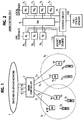
- the system includes a main controller 2 connected to the public or private telephone network 1 via three subscriber lines 61 through 63, for example.
- Main controller 2 is further connected by local lines 71 ⁇ 74 to access units 41 ⁇ 44 which are divided into groups corresponding to service zones 31 and 32 and located at strategic points of the corresponding service zones.
- the system has four cordless stations 51 through 54, for example, which may roam across the boundaries between service zones 31 and 32.
- a two-way control channel is provided between the access units and cordless stations. During standby modes, all access units and cordless stations are switched to the control channel to constantly monitor signals carried thereon. During a call origination or termination phase, the control channel is used to exchange control signals to assign a two-way speech channel.
- the frequency spectrum of the radio signals used in the system is equally divided at 12.5-kHz intervals into 89 (eighty-nine) telephone channels each with a bandwidth of 3 kHz.
- service zone 31 is permanently assigned an even-numbered control channel, say, channel #46 and a plurality of odd-numbered speech channels (channel #1 to channel #87), while zone 32 is permanently assigned an odd-numbered control channel, say, channel #89, and a plurality of even-numbered speech channels (channel #2 to channel #88) with the exception of channel #46.
- main controller 2 comprises line interfaces 81 ⁇ 83 respectively coupled via subscriber lines 61 ⁇ 63 to the network 1, local interfaces 101 ⁇ 104 respectively coupled to local lines 71 ⁇ 74, and a switching matrix 9 for establishing a connection between the interfaces 8 and 10.
- a control circuit 11 is coupled to all interfaces 8 and 10 to supply a switching control signal to matrix 9.
- An announcement source 11A is connected to all line interfaces 8 to supply a melodious tone and voiced announcement when an exchange line is kept in a line-hold condition in a manner as will be described.
- Control circuit 11 is connected to a call status memory 11B in which relationships between calls, exchange lines, access units and cordless stations are stored. Using the contents of call status memory 11B, control circuit 11 controls the switching matrix 9.
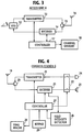
- each access unit 4 k includes a hybrid 12 having its two-wire circuit coupled to the associated local line 7 k .
- the transmit portion of the four-wire circuit is coupled to the input of a transmitter 13, the receive portion of the four-wire circuit being coupled to the output of a receiver 14.
- the output of transmitter 13 is coupled via a diplexer 15 to an antenna 16 for transmission to cordless stations.
- Signals received by antenna 16 from cordless stations are coupled by diplexer 15 to the input of receiver 14 for transmission to main controller 2.
- a frequency synthesizer is included in transmitter 13 and receiver 14 to receive control signals transmitted on the control channel from both sides of the access unit for coupling to a control circuit 17.
- control circuit 17 processes the received control signals for transmission to either side of the unit using a channel memory 18 in which the status of the control channel of the own zone and the status of all speech channels of the zone are stored.
- Each alert signal contains a system identifier and a cordless-station identifier.
- the frequency synthesizers of access units 41 and 42 are tuned to channel #46 during standby mode readying to receive signals and those of access units 43 and 44 are tuned to channel #89 during standby mode.
- signal from the nearby access unit is detected by an antenna 19 of each cordless station 5 k and passed through a diplexer 20 to a receiver 21 where it is converted to an audio-frequency signal and applied through a normally open switching circuit 22 to an earphone 23.
- Signal from microphone 24 is coupled through switching circuit 22 to a transmitter 25 where it is converted to a high-frequency signal and applied through diplexer 20 to antenna 19.
- a field intensity detector 26 is connected to receiver 21 to compare the field intensity of the cordless station with a prescribed threshold and applies an output signal to a control circuit 27 if the field intensity is higher than the threshold.
- control circuit 27 exchanges control signals with receiver 21 and transmitter 25 by successively tuning their frequency synthesizers to specified control channels and switching to an idle speech channel when it is assigned by the communicating access unit.
- a tone ringer 28 is connected to control circuit 27 to audibly alert the user upon receipt of an incoming call from the network.
- a keypad 29 is also connected to control circuit 27 to generate an off-hook signal when answering an incoming call or generate a call request as well as destination address information when originating an outgoing call.
- Each of the respective control circuits of main controller 2, access units 4 and cordless stations 5 is a microprocessor-based controller which is programmed to perform a stored sequence of instructions as described hereinbelow.
- step 30 the program execution of the controller 27 of a cordless station starts with decision step 30 to check the output of field intensity detector 26 to see if the field intensity is lower than an acceptable level. If this is the case, detector 26 generates an output and the program branches at step 30 to step 31 to switch the cordless station to the other control channel of the system to transmit a zone switching signal identifying the cordless station.
- the program proceeds to step 32 to switch the cordless station to the other control channel of the system, i.e., the control channel of a second zone to which the cordless station is about to enter, and moves ahead to step 33 to wait for an alert signal.
- control channels of other zones may be scanned to detect one having highest intensity as the control channel of the second zone and the zone switching signal may further contain an identifier indicating the control channel of the second zone.
- this zone switching signal is received by the access unit of a first zone and relayed to main controller 2.
- main controller 2 On receiving this zone switching signal, main controller 2 returns a disconnect signal to the access unit of the first zone, and then transmits an alert signal to one of the access units of a second zone.
- the alert signal is relayed from the access unit of the second zone to the cordless station in which it is detected at step 33.
- the program branches at step 33 to step 34 to transmit an acknowledgment (ACK) signal to the new access unit.
- ACK acknowledgment
- the access unit of the second zone On receiving this ACK signal, the access unit of the second zone returns a channel assignment signal to the cordless station, containing a channel identifier indicating a speech channel and the identifier of that cordless station to which the speech channel is to be assigned.
- step 35 The program proceeds to step 35 to check to see if a channel assignment signal is received. If this signal is not received within a specified period, control returns to step 34 to retransmit the acknowledgment signal.
- step 36 On receiving a channel assignment signal, the program branches at step 35 to step 36 to switch the cordless station to the assigned speech channel and transmits a switching complete signal to the access unit of the second zone (step 37).
- the switching complete signal is relayed by the access unit of the second zone to the main controller to cause it to transmit a turn-on signal.
- Control advances to step 38 to wait for the turn-on signal. If this turn-on signal is not received within a specified period, control returns to step 37 to retransmit the switching complete signal. On receiving this turn-on signal, cordless station operates switch 22 to reestablish a connection through the access unit to the main controller.
- Fig. 6A with a connection being established between a cordless station and an exchange line the program execution of the access unit 4 that is involved in the connection begins with decision step 40 to check for the presence of a zone switching signal from the cordless station. If the answer is affirmative, the program branches at step 40 to step 41 to relay the received zone switching signal to main controller 2 and goes to step 42 to wait for a disconnect signal from the main controller.
- main controller 2 responds to the zone switching signal by returning a disconnect signal to the access unit of the first zone.
- the program at the access unit branches at step 42 to step 43 to clear the connection to the cordless station, leaving the access unit in a standby state.
- step 44 when an access unit is in a standby state, the program execution starts with decision step 44 to check for the reception of an alert signal from the main controller.
- This alert signal contains the identifier of the cordless station crossing a zone boundary. If there is one, control branches at step 44 to step 45 to broadcast the alert signal, and goes to step 46 to wait for an acknowledgment signal returning from the addressed cordless station. This alert signal will be received by that cordless station and an acknowledgment signal will be returned therefrom. If the acknowledgment signal is not returned within a specified period, control branches to step 45 to rebroadcast the alert signal.
- step 46 On receiving the acknowledgment signal, the program branches at step 46 to step 47 to relay the acknowledgment signal to the main controller and proceeds to step 48 to scan all speech channels to select an idle channel and broadcast a channel assignment signal identifying the cordless station to which the selected idle speech channel is to be assigned and the identifier of the selected channel. Control exits to step 49 to wait for a switching complete signal returning from the cordless station.
- the cordless station will respond to the channel assignment signal from the access unit by reestablishing a link to the assigned speech channel and returning a switching complete signal to the access unit. If the switching complete signal is not received within a specified period, the program branches at step 49 to step 48 to repeat the transmission of the channel assignment signal.
- the program at the access unit branches at step 49 to step 50 to relay it to the main controller and moves to step 51 to wait for a turn-on signal from the main controller.
- the program of the access unit now branches to step 52 to broadcast the received turn-on signal to all cordless stations so that the cordless station entering the second zone is allowed to establish a speech path to enter a talking mode again with the exchange line.
- step 60 when a cordless station is in a talking mode through an exchange line, the program execution of main controller 2 begins with decision step 60 to check for the presence of a zone switching signal from the access unit through which the talking connection has been established. If there is one, control branches at step 60 to step 61 to hold the exchange line which is identified by a record in the call status memory 11B as corresponding to the cordless station from which the zone switching signal has been received, and applies a musical tone or a vocal announcement to the exchange line, indicating to the distant user that the key-telephone user is now crossing a zone boundary and the connection will be briefly interrupted. Exit then is to step 62 to return a disconnect signal to the access unit to allow it to clear the connection with the cordless telephone.
- step 63 to select one of the access units of the second zone and transmit an alert signal to the selected access unit. Exit then is to step 64 to check to see if an acknowledgment signal is received from the access unit of the second zone. If an acknowledgment signal is not received within a specified period, step 63 is repeated to retransmit the alert signal. If the answer is affirmative in step 64, control branches to decision step 65 to wait for a switching complete signal from the cordless station via the access unit. If there is one, the program branches to step 66 to connect the exchange line to the access unit of the second zone and proceeds to step 67 to transmit a turn-on signal to the access unit.
- a zone switching signal is transmitted (step 31) from station 51 and received and relayed by access unit 42 (steps 40 and 41, Fig. 6A) to main controller 2.
- Main controller 2 receives the zone switching signal (step 60, Fig. 7) and determines from the contents of call status memory 11B that exchange line 61 (step 61) is being connected to cordless station 51 and holds the line in an announcement mode and transmits a disconnect signal to access unit 42 (step 62).
- access unit 42 clears the connection to cordless station 51 (steps 42, 43, Fig. 6A).
- main controller 2 selects an access unit 43 and applies to it an alert signal identifying cordless station 51 (step 63, Fig. 7).
- This alert signal is received and broadcast by access unit 43 (steps 44, 45, Fig. 6B) and finally received by cordless station 51 (step 33, Fig. 5).
- Cordless station 51 returns an ACK signal (step 34), which is received and relayed by access unit 43 (step 47) to main controller 2 (step 64).
- Main controller 2 reconnects the exchange line 61 to access unit 43.
- access unit 43 scans the speech channels of zone 32 to select an idle channel and broadcasts a channel assignment signal identifying the selected channel and the cordless station 51 (step 48).
- the channel assignment signal is received by cordless station 51 (step 35) and cordless station 51 is switched to the assigned speech channel (step 36) to establish a connection between cordless station 51 and access unit 43.
- a switching complete signal is then transmitted from cordless station 51 (step 37) to access unit 43 and relayed to main controller 2 (steps 49, 50).
- Main controller 2 now connects the exchange line 61 to access unit 43 (step 66) and transmits a turn-on signal (step 67) to access unit 43, which, in turn, broadcasts it to cordless stations (steps 51, 52).
- Cordless station 51 responds to this turn-on signal by activating switch 22 and reestablishes the talking connection with the distant station via the exchange line 61 (steps 38 and 39, Fig. 5).
- Fig. 9 during a talking mode with an exchange line the program execution of a cordless station starts with decision step 70 to check to see if the field intensity is reduced to a level which indicates that the cordless station is leaving a first zone in which the talking connection has been established and entering a second zone. If the answer is affirmative, program branches at step 70 to step 71 to switch the cordless station to the control channel of the first zone and transmit a zone switching signal.
- the zone switching signal is received by the access unit of the first zone and relayed to the main controller in which the call status memory is accessed to detect an exchange line with which the cordless station is in talking mode.
- the main controller keeps the exchange line in an announcement-hold mode in a manner identical to the first embodiment by coupling the announcement source 11A to the line interface with which the exchange is connected.
- Control then proceeds to step 72 to check to see if the control channel of the second zone is idle. If the answer is affirmative, the program branches at step 72 to step 73 to switch the cordless station to the control channel of the second zone and transmit a call request signal to one of the access units of the second zone which is selected by the main controller, with the call request signal containing the cordless station identifier and the control channel identifier of the second zone. Control moves ahead to step 74 to wait for a channel assignment signal.
- the call request signal from the cordless station is relayed by the selected access unit to the main controller, whereupon it returns a disconnect signal to the access unit of the first zone to allow it to clear the connection to the cordless station. Meanwhile, the access unit of the second zone broadcasts a channel assignment signal.
- the program of the cordless station branches at step 74 to step 75 to switch the station to an idle speech channel specified by the channel assignment signal.
- the program then proceeds to step 76 to transmit a switching complete signal to the access unit of the second zone, and goes to step 77 to wait for a turn-on signal from the main controller via the access unit.
- the program branches at step 77 to step 78 to turn on the speech circuit switch 22 to reestablish the talking connection.
- Fig. 10A with a connection being established between a cordless station and an exchange line the program execution of the access unit that is involved in the connection begins with decision step 80 to check for the presence of a zone switching signal from the cordless station. If the answer is affirmative, the program branches at step 80 to step 81 to relay the received zone switching signal to main controller 2 and goes to step 82 to wait for a disconnect signal from the main controller. On receiving the disconnect signal, the program branches at step 82 to step 83 to clear the connection to the cordless station, leaving the access unit in a standby state.
- step 84 when an access unit is in a standby mode, the program execution starts with decision step 84 to check for the reception of a call request signal from a cordless station. If there is one, control branches at step 84 to step 85 to broadcast the relay the call request signal to the main controller, and goes to step 86 to scan all speech channels to select an idle channel and broadcast a channel assignment signal identifying the cordless station to which the selected idle speech channel is to be assigned and the selected channel identifier. Control exits to step 87 to wait for a switching complete signal from the cordless station. On receiving it, control branches to step 88 to relays it to the main controller and goes to decision step 89 to check for the reception of a turn-on signal from the main controller. When this signal is received, the program branches at step 89 to step 90 to broadcast the turn-on signal to cordless stations.
- step 100 when a cordless station is in a talking mode through an exchange line, the program execution of main controller 2 begins with decision step 100 to check for the presence of a zone switching signal from the access unit through which the talking connection has been established. If there is one, control branches at step 100 to step 101 to hold the exchange line which is identified by the call status memory of controller 11 as corresponding to the cordless station from which the zone switching signal has been received, and applies a musical tone or a vocal announcement to the exchange line, indicating to the distant user that the key-telephone user is now leaving a first zone and entering a second zone and the connection will be briefly interrupted. Exit then is to decision step 102 to wait for a call request signal from the cordless station by way of an access unit of the second zone.
- step 102 On receiving the call request signal, the program branches at step 102 to step 103 to transmit a disconnect signal to the access unit of the first zone to allow it to clear the connection with the cordless station which has left the first zone. Exit then is to step 104 to check to see if a switching complete signal is received from the access unit of the second zone. If the answer is affirmative in step 104, control branches to step 105 to connect the exchange line to the access unit and exits to step 106 to transmit a turn-on signal to the access unit of the second zone.
- a zone switching signal is transmitted (step 71) from station 51 and received and relayed by access unit 42 (steps 80 and 81, Fig. 10A) to main controller 2.
- Main controller 2 receives the zone switching signal (step 100, Fig. 11) and determines from the call status memory of controller 11 that exchange line 61 (step 101) is being connected to cordless station 51 and holds the line in an announcement mode.
- cordless station 51 When cordless station 51 has entered the second zone, the field intensity of the control channel of the second zone detected by the station will become higher than a specified level (step 72) and a call request signal is sent from cordless station 51 to access unit 43 (step 73).
- the call request signal is relayed by access unit 43 (steps 84, 85, Fig. 10B) to the main controller, whereupon it proceeds to transmit a disconnect signal to access unit 42 (steps 102 and 103, Fig. 11).
- access unit 42 clears the connection to cordless station 51 (steps 82, 83, Fig. 10A).
- access unit 43 responds to the call request signal from station 51 by scanning speech channels of the second zone and selects one of the idle channels and broadcasts a channels assignment signal.
- Cordless station 51 receives this signal (step 74) and switches to the assigned speech channel (step 75).
- a switching complete signal is then transmitted from cordless station 51 to access unit 43 (step 76) and relayed to main controller 2 (steps 87, 88).
- main controller 2 connects the exchange line 61 to access unit 43 (step 105) and transmits a turn-on signal (step 106) to access unit 43, which, in turn, broadcasts it to cordless stations (steps 89, 90).
- Cordless station 51 responds to this turn-on signal by activating switch 22 and reestablishes the talking connection with the distant station via the exchange line 61 (steps 77, 78, Fig. 9).
Abstract

Description
- The present invention relates to a cordless key telephone system.
- Cordless key telephone systems have been in widespread use replacing wired key telephone systems to reduce the amount of cables and wires laid on office floors. The system usually includes a main controller which is coupled to the public or private switched telephone network via exchange lines to receive incoming calls and originate outgoing calls. The floor space is divided into several service zones to which control channels are uniquely assigned. One or more access units are located in each service zone and coupled to the main controller to relay control signals between it and the cordless stations before establishing a connection through a speech channel. The cordless station is provided with a field intensity detector for alerting the user when the field intensity reduces below an acceptable level.
- When the user of a given cordless station is in conversation with a distant network-side party via an exchange line while walking across a boundary between adjacent zones, the user will be alerted by the field intensity detector and would request the distant party to wait for a moment, and depress a "hold" key to trigger a signal. The main controller receives this signal to hold the exchange line and sends back a signal to the cordless station to give a visual indication to the user, indicating that the exchange line is kept in a line-hold mode, while triggering a timeout circuit to measure the length of time in which the line-hold mode is continued. If a prescribed period is expired the exchange line is forcibly disconnected. On seeing the visual indication, the user is supposed to depress an end-of-call key to allow the cordless station to switch to standby mode. The end-of-call key causes a signal to be transmitted to the main controller to record the status of the call in a call status memory so that the exchange line can be accessed exclusively from the cordless station. On entering the second zone, the station user is supposed to depress a call request key signalling the origination of a call to an access unit of the second zone, and thence to the main controller. On receiving the call request, the access unit searches speech channels to assign an idle channel and returns a channel assignment signal to the cordless station to cause it to switch to the assigned channel. On the other hand, the main controller responds to the call request by accessing the call status memory and establishing a connection between the exchange line and the access unit of the second zone according to the recorded call status.
- Since the conventional cordless key telephone system processes zone switching events in response to manual key commands, delayed operations of the keys may inadvertently allow the timeout circuit to disconnect the exchange line, leaving the network-side party in a state of embarrassment.
- It is therefore an object of the present invention to provide a cordless key telephone system having multiple control channels assigned respectively to different service zones, wherein the station users are allowed to move across a zone boundary while keeping a call with a network-side user without bothering to enter key commands.
- According to the present invention, there is provided a cordless key telephone system for covering a plurality of service zones. The system includes a plurality of access units respectively located in the service zones. A plurality of cordless stations are located in the service zones. Each cordless station establishes a two-way radio channel with the access unit of the service zone in which it is located, and constantly monitors the field intensity of the established channel and transmits a zone switching signal when the field intensity is below a specified level as an indication that the cordless station is leaving a first service zone and entering a second service zone. A main controller establishes a switched connection between exchange lines and the access units and is responsive to the zone switching signal from a given cordless station via the access unit of the first service zone for holding an exchange line that is connected to the access unit of the first service zone through a first switched connection, and establishes a second switched connection between the exchange line and the access unit of the second service zone, instead of the first switched connection.
- In one embodiment of the present invention, the main controller is responsive to the zone switching signal for transmitting a disconnect signal to the access unit of the first service zone and transmitting an alert signal to the given cordless station via the access unit of the second service zone to elicit an acknowledgment signal therefrom. The access unit of the first service zone is responsive to the disconnect signal for clearing the channel established therefrom to the given cordless station for readying to receive signals in a standby mode, and the access unit of the second service zone is responsive to the acknowledgment signal for transmitting to the given cordless station a channel assignment signal indicating an idle speech channel to be assigned to the given cordless station.
- In another embodiment of the present invention, the cordless station transmits a call request signal to the access unit of the second service zone following the transmission of the zone switching signal. The access unit of the second service zone is responsive to the call request signal for transmitting to the cordless station a channel assignment signal. The main controller is responsive to the call request signal received via the access unit of the second service zone for transmitting a disconnect signal to the access unit of the first service zone for clearing the channel established therefrom to the cordless station for readying to receive signals in a standby mode.
- The present invention will be described in further detail with reference to the accompanying drawings, in which:
- Fig. 1 shows in block form a cordless key telephone system embodying the present invention;
- Fig. 2 shows details of a main controller;
- Fig. 3 shows details of an access unit;
- Fig. 4 shows details of a cordless station;
- Fig. 5 shows instructions programmed in the controller of cordless stations according to a first embodiment of this invention;
- Figs. 6A and 6B show instructions programmed in the controller of access units according to the first embodiment of this invention;
- Fig. 7 shows instructions programmed in the main controller according to the first embodiment of this invention;
- Fig. 8 shows a sequence of signals useful for describing the operation of the system according to the first embodiment of this invention;
- Fig. 9 shows instructions programmed in the controller of cordless stations according to a second embodiment of this invention;
- Figs. 10A and 10B show instructions programmed in the controller of access units according to the second embodiment of this invention;
- Fig. 11 shows instructions programmed in the main controller according to the second embodiment of this invention; and
- Fig. 12 shows a sequence of signals useful for describing the operation of the system according to the second embodiment of this invention.
- Referring now to Fig. 1, there is shown a cordless key telephone system according to the present invention. The system includes a
main controller 2 connected to the public or private telephone network 1 via threesubscriber lines 6₁ through 6₃, for example.Main controller 2 is further connected bylocal lines 7₁∼7₄ to accessunits 4₁∼4₄ which are divided into groups corresponding toservice zones cordless stations 5₁ through 5₄, for example, which may roam across the boundaries betweenservice zones - The frequency spectrum of the radio signals used in the system is equally divided at 12.5-kHz intervals into 89 (eighty-nine) telephone channels each with a bandwidth of 3 kHz. In order to avoid interference between control signals and speech signals due to third-order intermodulation distortion,
service zone 3₁ is permanently assigned an even-numbered control channel, say,channel # 46 and a plurality of odd-numbered speech channels (channel #1 to channel #87), whilezone 3₂ is permanently assigned an odd-numbered control channel, say,channel # 89, and a plurality of even-numbered speech channels (channel # 2 to channel #88) with the exception ofchannel # 46. - As shown in Fig. 2,
main controller 2 comprisesline interfaces 8₁∼8₃ respectively coupled viasubscriber lines 6₁∼6₃ to the network 1,local interfaces 10₁∼10₄ respectively coupled tolocal lines 7₁∼7₄, and a switching matrix 9 for establishing a connection between the interfaces 8 and 10. Acontrol circuit 11 is coupled to all interfaces 8 and 10 to supply a switching control signal to matrix 9. Anannouncement source 11A is connected to all line interfaces 8 to supply a melodious tone and voiced announcement when an exchange line is kept in a line-hold condition in a manner as will be described.Control circuit 11 is connected to acall status memory 11B in which relationships between calls, exchange lines, access units and cordless stations are stored. Using the contents ofcall status memory 11B,control circuit 11 controls the switching matrix 9. - As illustrated in Fig. 3, each
access unit 4k includes ahybrid 12 having its two-wire circuit coupled to the associated local line 7k. The transmit portion of the four-wire circuit is coupled to the input of atransmitter 13, the receive portion of the four-wire circuit being coupled to the output of areceiver 14. The output oftransmitter 13 is coupled via adiplexer 15 to anantenna 16 for transmission to cordless stations. Signals received byantenna 16 from cordless stations are coupled bydiplexer 15 to the input ofreceiver 14 for transmission tomain controller 2. A frequency synthesizer is included intransmitter 13 andreceiver 14 to receive control signals transmitted on the control channel from both sides of the access unit for coupling to acontrol circuit 17. In a manner to be described,control circuit 17 processes the received control signals for transmission to either side of the unit using achannel memory 18 in which the status of the control channel of the own zone and the status of all speech channels of the zone are stored. Each alert signal contains a system identifier and a cordless-station identifier. The frequency synthesizers ofaccess units channel # 46 during standby mode readying to receive signals and those ofaccess units channel # 89 during standby mode. - In Fig. 4, signal from the nearby access unit is detected by an
antenna 19 of eachcordless station 5k and passed through adiplexer 20 to areceiver 21 where it is converted to an audio-frequency signal and applied through a normallyopen switching circuit 22 to anearphone 23. Signal frommicrophone 24 is coupled through switchingcircuit 22 to atransmitter 25 where it is converted to a high-frequency signal and applied throughdiplexer 20 toantenna 19. Afield intensity detector 26 is connected toreceiver 21 to compare the field intensity of the cordless station with a prescribed threshold and applies an output signal to acontrol circuit 27 if the field intensity is higher than the threshold. As will be described,control circuit 27 exchanges control signals withreceiver 21 andtransmitter 25 by successively tuning their frequency synthesizers to specified control channels and switching to an idle speech channel when it is assigned by the communicating access unit. Atone ringer 28 is connected to controlcircuit 27 to audibly alert the user upon receipt of an incoming call from the network. Akeypad 29 is also connected to controlcircuit 27 to generate an off-hook signal when answering an incoming call or generate a call request as well as destination address information when originating an outgoing call. - Each of the respective control circuits of
main controller 2,access units 4 andcordless stations 5 is a microprocessor-based controller which is programmed to perform a stored sequence of instructions as described hereinbelow. - A first embodiment of the present invention will now be described with reference to flowcharts shown in Figs. 5 to 7.
- In Fig. 5, during a talking mode with a distant station via an exchange line the program execution of the
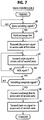
controller 27 of a cordless station starts withdecision step 30 to check the output offield intensity detector 26 to see if the field intensity is lower than an acceptable level. If this is the case,detector 26 generates an output and the program branches atstep 30 to step 31 to switch the cordless station to the other control channel of the system to transmit a zone switching signal identifying the cordless station. The program proceeds to step 32 to switch the cordless station to the other control channel of the system, i.e., the control channel of a second zone to which the cordless station is about to enter, and moves ahead to step 33 to wait for an alert signal. If the system has three or more control channels assigned respectively to different zones, control channels of other zones may be scanned to detect one having highest intensity as the control channel of the second zone and the zone switching signal may further contain an identifier indicating the control channel of the second zone. - As will be described, this zone switching signal is received by the access unit of a first zone and relayed to
main controller 2. On receiving this zone switching signal,main controller 2 returns a disconnect signal to the access unit of the first zone, and then transmits an alert signal to one of the access units of a second zone. - The alert signal is relayed from the access unit of the second zone to the cordless station in which it is detected at
step 33. The program branches atstep 33 to step 34 to transmit an acknowledgment (ACK) signal to the new access unit. - On receiving this ACK signal, the access unit of the second zone returns a channel assignment signal to the cordless station, containing a channel identifier indicating a speech channel and the identifier of that cordless station to which the speech channel is to be assigned.
- The program proceeds to step 35 to check to see if a channel assignment signal is received. If this signal is not received within a specified period, control returns to step 34 to retransmit the acknowledgment signal. On receiving a channel assignment signal, the program branches at
step 35 to step 36 to switch the cordless station to the assigned speech channel and transmits a switching complete signal to the access unit of the second zone (step 37). - The switching complete signal is relayed by the access unit of the second zone to the main controller to cause it to transmit a turn-on signal.
- Control advances to step 38 to wait for the turn-on signal. If this turn-on signal is not received within a specified period, control returns to step 37 to retransmit the switching complete signal. On receiving this turn-on signal, cordless station operates
switch 22 to reestablish a connection through the access unit to the main controller. - In Fig. 6A, with a connection being established between a cordless station and an exchange line the program execution of the
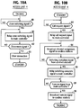
access unit 4 that is involved in the connection begins withdecision step 40 to check for the presence of a zone switching signal from the cordless station. If the answer is affirmative, the program branches atstep 40 to step 41 to relay the received zone switching signal tomain controller 2 and goes to step 42 to wait for a disconnect signal from the main controller. - As will be described,
main controller 2 responds to the zone switching signal by returning a disconnect signal to the access unit of the first zone. On receiving it, the program at the access unit branches atstep 42 to step 43 to clear the connection to the cordless station, leaving the access unit in a standby state. - In Fig. 6B, when an access unit is in a standby state, the program execution starts with
decision step 44 to check for the reception of an alert signal from the main controller. This alert signal contains the identifier of the cordless station crossing a zone boundary. If there is one, control branches atstep 44 to step 45 to broadcast the alert signal, and goes to step 46 to wait for an acknowledgment signal returning from the addressed cordless station. This alert signal will be received by that cordless station and an acknowledgment signal will be returned therefrom. If the acknowledgment signal is not returned within a specified period, control branches to step 45 to rebroadcast the alert signal. - On receiving the acknowledgment signal, the program branches at
step 46 to step 47 to relay the acknowledgment signal to the main controller and proceeds to step 48 to scan all speech channels to select an idle channel and broadcast a channel assignment signal identifying the cordless station to which the selected idle speech channel is to be assigned and the identifier of the selected channel. Control exits to step 49 to wait for a switching complete signal returning from the cordless station. - The cordless station will respond to the channel assignment signal from the access unit by reestablishing a link to the assigned speech channel and returning a switching complete signal to the access unit. If the switching complete signal is not received within a specified period, the program branches at
step 49 to step 48 to repeat the transmission of the channel assignment signal. - In response to receipt of a switching complete signal, the program at the access unit branches at
step 49 to step 50 to relay it to the main controller and moves to step 51 to wait for a turn-on signal from the main controller. - The program of the access unit now branches to step 52 to broadcast the received turn-on signal to all cordless stations so that the cordless station entering the second zone is allowed to establish a speech path to enter a talking mode again with the exchange line.
- In Fig. 7, when a cordless station is in a talking mode through an exchange line, the program execution of
main controller 2 begins withdecision step 60 to check for the presence of a zone switching signal from the access unit through which the talking connection has been established. If there is one, control branches atstep 60 to step 61 to hold the exchange line which is identified by a record in thecall status memory 11B as corresponding to the cordless station from which the zone switching signal has been received, and applies a musical tone or a vocal announcement to the exchange line, indicating to the distant user that the key-telephone user is now crossing a zone boundary and the connection will be briefly interrupted. Exit then is to step 62 to return a disconnect signal to the access unit to allow it to clear the connection with the cordless telephone. The program then proceeds to step 63 to select one of the access units of the second zone and transmit an alert signal to the selected access unit. Exit then is to step 64 to check to see if an acknowledgment signal is received from the access unit of the second zone. If an acknowledgment signal is not received within a specified period,step 63 is repeated to retransmit the alert signal. If the answer is affirmative instep 64, control branches todecision step 65 to wait for a switching complete signal from the cordless station via the access unit. If there is one, the program branches to step 66 to connect the exchange line to the access unit of the second zone and proceeds to step 67 to transmit a turn-on signal to the access unit. - The operation of the first embodiment of the system will now be described with reference to the drawings described above together with Fig. 8. Assume that
cordless station 5₁ is in a talking mode withexchange line 6₁ by way ofaccess unit 4₂ and is leavingzone 3₁ and enteringsecond zone 3₂. When a low field intensity condition is detected (step 30, Fig. 5), a zone switching signal is transmitted (step 31) fromstation 5₁ and received and relayed by access unit 4₂ (steps main controller 2.Main controller 2 receives the zone switching signal (step 60, Fig. 7) and determines from the contents ofcall status memory 11B that exchange line 6₁ (step 61) is being connected tocordless station 5₁ and holds the line in an announcement mode and transmits a disconnect signal to access unit 4₂ (step 62). On receiving this disconnect signal,access unit 4₂ clears the connection to cordless station 5₁ (steps main controller 2 selects anaccess unit 4₃ and applies to it an alert signal identifying cordless station 5₁ (step 63, Fig. 7). This alert signal is received and broadcast by access unit 4₃ (steps step 33, Fig. 5).Cordless station 5₁ returns an ACK signal (step 34), which is received and relayed by access unit 4₃ (step 47) to main controller 2 (step 64).Main controller 2 reconnects theexchange line 6₁ to accessunit 4₃. - Meanwhile,
access unit 4₃ scans the speech channels ofzone 3₂ to select an idle channel and broadcasts a channel assignment signal identifying the selected channel and the cordless station 5₁ (step 48). The channel assignment signal is received by cordless station 5₁ (step 35) andcordless station 5₁ is switched to the assigned speech channel (step 36) to establish a connection betweencordless station 5₁ andaccess unit 4₃. A switching complete signal is then transmitted from cordless station 5₁ (step 37) to accessunit 4₃ and relayed to main controller 2 (steps 49, 50).Main controller 2 now connects theexchange line 6₁ to access unit 4₃ (step 66) and transmits a turn-on signal (step 67) to accessunit 4₃, which, in turn, broadcasts it to cordless stations (steps 51, 52).Cordless station 5₁ responds to this turn-on signal by activatingswitch 22 and reestablishes the talking connection with the distant station via the exchange line 6₁ (steps - A second embodiment of the present invention will now be described with reference to flowcharts shown in Figs. 9 to 11.
- In Fig. 9, during a talking mode with an exchange line the program execution of a cordless station starts with
decision step 70 to check to see if the field intensity is reduced to a level which indicates that the cordless station is leaving a first zone in which the talking connection has been established and entering a second zone. If the answer is affirmative, program branches atstep 70 to step 71 to switch the cordless station to the control channel of the first zone and transmit a zone switching signal. - As will be described, the zone switching signal is received by the access unit of the first zone and relayed to the main controller in which the call status memory is accessed to detect an exchange line with which the cordless station is in talking mode. The main controller keeps the exchange line in an announcement-hold mode in a manner identical to the first embodiment by coupling the
announcement source 11A to the line interface with which the exchange is connected. - Control then proceeds to step 72 to check to see if the control channel of the second zone is idle. If the answer is affirmative, the program branches at
step 72 to step 73 to switch the cordless station to the control channel of the second zone and transmit a call request signal to one of the access units of the second zone which is selected by the main controller, with the call request signal containing the cordless station identifier and the control channel identifier of the second zone. Control moves ahead to step 74 to wait for a channel assignment signal. - As will be described, the call request signal from the cordless station is relayed by the selected access unit to the main controller, whereupon it returns a disconnect signal to the access unit of the first zone to allow it to clear the connection to the cordless station. Meanwhile, the access unit of the second zone broadcasts a channel assignment signal.
- On receiving the channel assignment signal, the program of the cordless station branches at
step 74 to step 75 to switch the station to an idle speech channel specified by the channel assignment signal. The program then proceeds to step 76 to transmit a switching complete signal to the access unit of the second zone, and goes to step 77 to wait for a turn-on signal from the main controller via the access unit. When the turn-on signal is received by the cordless station, the program branches at step 77 to step 78 to turn on thespeech circuit switch 22 to reestablish the talking connection. - In Fig. 10A, with a connection being established between a cordless station and an exchange line the program execution of the access unit that is involved in the connection begins with
decision step 80 to check for the presence of a zone switching signal from the cordless station. If the answer is affirmative, the program branches atstep 80 to step 81 to relay the received zone switching signal tomain controller 2 and goes to step 82 to wait for a disconnect signal from the main controller. On receiving the disconnect signal, the program branches atstep 82 to step 83 to clear the connection to the cordless station, leaving the access unit in a standby state. - In Fig. 10B, when an access unit is in a standby mode, the program execution starts with
decision step 84 to check for the reception of a call request signal from a cordless station. If there is one, control branches atstep 84 to step 85 to broadcast the relay the call request signal to the main controller, and goes to step 86 to scan all speech channels to select an idle channel and broadcast a channel assignment signal identifying the cordless station to which the selected idle speech channel is to be assigned and the selected channel identifier. Control exits to step 87 to wait for a switching complete signal from the cordless station. On receiving it, control branches to step 88 to relays it to the main controller and goes todecision step 89 to check for the reception of a turn-on signal from the main controller. When this signal is received, the program branches atstep 89 to step 90 to broadcast the turn-on signal to cordless stations. - In Fig. 11, when a cordless station is in a talking mode through an exchange line, the program execution of
main controller 2 begins withdecision step 100 to check for the presence of a zone switching signal from the access unit through which the talking connection has been established. If there is one, control branches atstep 100 to step 101 to hold the exchange line which is identified by the call status memory ofcontroller 11 as corresponding to the cordless station from which the zone switching signal has been received, and applies a musical tone or a vocal announcement to the exchange line, indicating to the distant user that the key-telephone user is now leaving a first zone and entering a second zone and the connection will be briefly interrupted. Exit then is todecision step 102 to wait for a call request signal from the cordless station by way of an access unit of the second zone. On receiving the call request signal, the program branches atstep 102 to step 103 to transmit a disconnect signal to the access unit of the first zone to allow it to clear the connection with the cordless station which has left the first zone. Exit then is to step 104 to check to see if a switching complete signal is received from the access unit of the second zone. If the answer is affirmative instep 104, control branches to step 105 to connect the exchange line to the access unit and exits to step 106 to transmit a turn-on signal to the access unit of the second zone. - The operation of the second embodiment of the system will now be described with reference to Figs. 9-12. As in the case of the first embodiment, it is assumed that
cordless station 5₁ is in a talking mode withexchange line 6₁ by way ofaccess unit 4₂ and is leavingfirst zone 3₁ and enteringsecond zone 3₂. When a low field intensity condition is detected (step 70, Fig. 9), a zone switching signal is transmitted (step 71) fromstation 5₁ and received and relayed by access unit 4₂ (steps main controller 2.Main controller 2 receives the zone switching signal (step 100, Fig. 11) and determines from the call status memory ofcontroller 11 that exchange line 6₁ (step 101) is being connected tocordless station 5₁ and holds the line in an announcement mode. Whencordless station 5₁ has entered the second zone, the field intensity of the control channel of the second zone detected by the station will become higher than a specified level (step 72) and a call request signal is sent fromcordless station 5₁ to access unit 4₃ (step 73). The call request signal is relayed by access unit 4₃ (steps steps access unit 4₂ clears the connection to cordless station 5₁ (steps - Meanwhile,
access unit 4₃ responds to the call request signal fromstation 5₁ by scanning speech channels of the second zone and selects one of the idle channels and broadcasts a channels assignment signal.Cordless station 5₁ receives this signal (step 74) and switches to the assigned speech channel (step 75). A switching complete signal is then transmitted fromcordless station 5₁ to access unit 4₃ (step 76) and relayed to main controller 2 (steps 87, 88). In response to the switching complete signal (step 104),main controller 2 connects theexchange line 6₁ to access unit 4₃ (step 105) and transmits a turn-on signal (step 106) to accessunit 4₃, which, in turn, broadcasts it to cordless stations (steps 89, 90).Cordless station 5₁ responds to this turn-on signal by activatingswitch 22 and reestablishes the talking connection with the distant station via the exchange line 6₁ (steps 77, 78, Fig. 9).
Claims (6)
- A cordless key telephone system for covering a plurality of service zones, comprising:
a plurality of access units (4₁∼4₄) respectively located in the service zones (3₁, 3₂);
a plurality of cordless stations (5) movable across boundaries of said service zones, each of the cordless stations establishing a two-way radio channel with the access unit of the service zone in which the cordless station is located, and including means for constantly monitoring field intensity of the established channel and transmitting a zone switching signal when the field intensity is below a specified level as an indication that the cordless station is leaving a first service zone and entering a second service zone; and
a main controller (2) for establishing a switched connection between exchange lines (6₁-6₃) and said access units (4₁∼4₄) and responsive to said zone switching signal from a given cordless station via the access unit of the first service zone for holding an exchange line which is connected to the access unit of the first service zone through a first switched connection, and establishing a second switched connection between said exchange line and the access unit of the second service zone instead of the first switched connection. - A cordless key telephone system as claimed in claim 1, wherein said main controller is responsive to said zone switching signal for transmitting a disconnect signal to the access unit of the first service zone (3₁) and transmitting an alert signal to the given cordless station via the access unit of said second service zone to elicit an acknowledgment signal from said given cordless station, and wherein the access unit of the first service zone is responsive to the disconnect signal for clearing the channel to the given cordless station for readying to receive signals in a standby mode, and wherein the access unit of the second service zone is responsive to the acknowledgment signal for transmitting to said given cordless station a channel assignment signal indicating an idle speech channel to be assigned to said given cordless station.
- A cordless key telephone system as claimed in claim 1 or 2, wherein said given cordless stations includes means for transmitting a call request signal to the access unit of said second service zone (3₂) following the transmission of said zone switching signal, wherein the access unit of said second service zone (3₂) is responsive to said call request signal for transmitting to said given cordless station a channel assignment signal indicating an idle speech channel to be assigned to said given cordless station, and wherein the main controller (2) is responsive to said call request signal via the access unit of the second service zone (3₂) for transmitting a disconnect signal to the access unit of the first service zone for clearing the channel established therefrom to the given cordless station for readying to receive signals in a standby mode.
- A cordless key telephone system for covering a plurality of service zones each having a uniquely assigned two-way control channel and a plurality of two-way speech channels, comprising:
a plurality of access units (4₁∼4₄) respectively located in said service zones (3₁, 3₂);
a plurality of cordless stations (5) movable across boundaries of said service zones, each of the cordless stations establishing a first control connection to the access unit of a first service zone (3₁), in which the cordless station is located, through the control channel of said first service zone and subsequently establishing a speech connection to said access unit through one of the speech channels of the first service zone instead of the first control connection, and including means (26) for constantly monitoring field intensity of the established speech connection, reestablishing the first control connection and transmitting a zone switching signal when the field intensity is below a specified level as an indication that the cordless station is leaving said first service zone (3₁) and entering a second service zone (3₂), and establishing a second control connection to the access unit of the second service zone through the control channel of the second service zone; and
a main controller (2) for establishing a switched connection between exchange lines (6₁-6₃) and said access units and responsive to said zone switching signal from a given cordless station via the access unit of the first service zone for holding an exchange line which is connected to the access unit of the first service zone through a first switched connection, and establishing a second switched connection between said exchange line and the access unit of the second service zone instead of the first switched connection. - A cordless key telephone system as claimed in claim 4, wherein said main controller (2) is responsive to said zone switching signal for transmitting a disconnect signal to the access unit of the first service zone (3₁) and transmitting an alert signal to the given cordless station via said second control connection to elicit an acknowledgment signal from the given cordless station, and wherein the access unit of the first service zone (3₁) is responsive to the disconnect signal for clearing the second control connection for readying to receive signals in a standby mode, and wherein the access unit of the second service zone (3₂) is responsive to the acknowledgment signal for transmitting to said given cordless station a channel assignment signal indicating an idle speech channel to be assigned to said given cordless station.
- A cordless key telephone system as claimed in claim 4 or 5, wherein said given cordless stations includes means for transmitting a call request signal through said second control connection to the access unit of said second service zone (3₂) following the transmission of said zone switching signal, wherein the access unit (3₂) of said second service zone is responsive to said call request signal for transmitting to said given cordless station a channel assignment signal indicating an idle speech channel to be assigned to said given cordless station, and wherein the main controller (2) is responsive to said call request signal via the access unit of the second service zone (3₂) for transmitting a disconnect signal to the access unit of the first service zone for clearing the second control connection for readying to receive signals in a standby mode.
Applications Claiming Priority (4)
| Application Number | Priority Date | Filing Date | Title |
|---|---|---|---|
| JP2238964A JPH04119726A (en) | 1990-09-11 | 1990-09-11 | Zone changeover system for radio telephone system |
| JP2238965A JPH04119727A (en) | 1990-09-11 | 1990-09-11 | Zone changeover system for radio telephone system |
| JP238965/90 | 1990-09-11 | ||
| JP238964/90 | 1990-09-11 |
Publications (3)
| Publication Number | Publication Date |
|---|---|
| EP0475348A2 true EP0475348A2 (en) | 1992-03-18 |
| EP0475348A3 EP0475348A3 (en) | 1993-03-03 |
| EP0475348B1 EP0475348B1 (en) | 1999-03-10 |
Family
ID=26534009
Family Applications (1)
| Application Number | Title | Priority Date | Filing Date |
|---|---|---|---|
| EP91115272A Expired - Lifetime EP0475348B1 (en) | 1990-09-11 | 1991-09-10 | Cordless key telephone system having zone switching function |
Country Status (6)
| Country | Link |
|---|---|
| US (1) | US5454028A (en) |
| EP (1) | EP0475348B1 (en) |
| KR (1) | KR950013162B1 (en) |
| AU (1) | AU650044B2 (en) |
| CA (1) | CA2051086C (en) |
| DE (1) | DE69130973T2 (en) |
Cited By (5)
| Publication number | Priority date | Publication date | Assignee | Title |
|---|---|---|---|---|
| EP0569645A1 (en) * | 1991-04-12 | 1993-11-18 | Dassault Automatismes Et Telecommunications | Method and arrangement for telephone connections with continuity of service in a communication network with autonomous stations |
| US5311571A (en) * | 1992-05-14 | 1994-05-10 | Motorola, Inc. | Method and apparatus for performing inbound calling in a wireless communication system having fixed communication units coupled to a telephone system by a telephone line shared in common |
| TR27974A (en) * | 1992-06-30 | 1995-11-01 | Dassault Automatismes | Device and method for telephone interconnection intended to provide service continuity to independent stations within a communication network. |
| EP0898435A2 (en) * | 1997-08-16 | 1999-02-24 | Deutsche Telekom AG | Digital cordless telephone system |
| CN1082319C (en) * | 1995-07-24 | 2002-04-03 | 三星电子株式会社 | Cordless private automatic branch exchange |
Families Citing this family (22)
| Publication number | Priority date | Publication date | Assignee | Title |
|---|---|---|---|---|
| US5790587A (en) | 1991-05-13 | 1998-08-04 | Omnipoint Corporation | Multi-band, multi-mode spread-spectrum communication system |
| US5694414A (en) | 1991-05-13 | 1997-12-02 | Omnipoint Corporation | Multi-band, multi-mode spread-spectrum communication system |
| US5887020A (en) | 1991-05-13 | 1999-03-23 | Omnipoint Corporation | Multi-band, multi-mode spread-spectrum communication system |
| US5796772A (en) | 1991-05-13 | 1998-08-18 | Omnipoint Corporation | Multi-band, multi-mode spread-spectrum communication system |
| US5815525A (en) | 1991-05-13 | 1998-09-29 | Omnipoint Corporation | Multi-band, multi-mode spread-spectrum communication system |
| US5285469A (en) | 1991-06-03 | 1994-02-08 | Omnipoint Data Corporation | Spread spectrum wireless telephone system |
| AU660975B2 (en) * | 1992-05-19 | 1995-07-13 | Dassault Automatismes Et Telecommunications | Device and method for telephony interconnection intended to offer continuity of service to independent stations in a communications network |
| GB2282730B (en) * | 1993-10-08 | 1998-01-28 | Nokia Telecommunications Oy | Dual mode subscriber terminal and a handover procedure of the dual mode subscriber terminal in a mobile telecommunication network |
| US6301242B1 (en) | 1998-07-24 | 2001-10-09 | Xircom Wireless, Inc. | Communication system with fast control traffic |
| US6005856A (en) | 1993-11-01 | 1999-12-21 | Omnipoint Corporation | Communication protocol for spread spectrum wireless communication system |
| US6088590A (en) | 1993-11-01 | 2000-07-11 | Omnipoint Corporation | Method and system for mobile controlled handoff and link maintenance in spread spectrum communication |
| IL111469A0 (en) | 1993-11-01 | 1994-12-29 | Omnipoint Corp | Despreading/demodulating direct sequence spread spectrum signals |
| US6094575A (en) | 1993-11-01 | 2000-07-25 | Omnipoint Corporation | Communication system and method |
| US5745484A (en) | 1995-06-05 | 1998-04-28 | Omnipoint Corporation | Efficient communication system using time division multiplexing and timing adjustment control |
| US5959980A (en) | 1995-06-05 | 1999-09-28 | Omnipoint Corporation | Timing adjustment control for efficient time division duplex communication |
| US5689502A (en) * | 1995-06-05 | 1997-11-18 | Omnipoint Corporation | Efficient frequency division duplex communication system with interleaved format and timing adjustment control |
| US5802046A (en) * | 1995-06-05 | 1998-09-01 | Omnipoint Corporation | Efficient time division duplex communication system with interleaved format and timing adjustment control |
| US6272121B1 (en) * | 1997-03-03 | 2001-08-07 | Omnipoint Corporation | Spread spectrum communication system using DECT protocol |
| US6571096B2 (en) * | 1998-11-12 | 2003-05-27 | Fujitsu Limited | Method and device for preventing toggling between two zones of a wireless communications network |
| JP4207005B2 (en) * | 2005-01-28 | 2009-01-14 | ブラザー工業株式会社 | Cordless equipment |
| US7747544B2 (en) * | 2005-12-07 | 2010-06-29 | Pitney Bowes Inc. | Meter tape with location indicator used for unique identification |
| US7920524B2 (en) * | 2006-09-29 | 2011-04-05 | Vixs Systems, Inc. | Multimedia server with channel control module and methods for use therewith |
Citations (6)
| Publication number | Priority date | Publication date | Assignee | Title |
|---|---|---|---|---|
| DE2625475A1 (en) * | 1976-06-05 | 1978-04-06 | Licentia Gmbh | Radio communications network for mobile stations - reroutes connection via second local switching centre when mobile station leaves area of first one |
| JPS5595438A (en) * | 1979-01-11 | 1980-07-19 | Nec Corp | Channel switching system of car telephone |
| US4352955A (en) * | 1979-02-14 | 1982-10-05 | Nippon Electric Co., Ltd. | Control signal transmission system for use in a mobile radio communication system |
| EP0325713A2 (en) * | 1988-01-29 | 1989-08-02 | Motorola, Inc. | Cellular radiotelephone system with dropped call protection |
| EP0369535A2 (en) * | 1988-11-16 | 1990-05-23 | Philips Electronics Uk Limited | Cellular radio system |
| EP0443503A2 (en) * | 1990-02-23 | 1991-08-28 | Mitsubishi Denki Kabushiki Kaisha | Mobile communication system |
Family Cites Families (4)
| Publication number | Priority date | Publication date | Assignee | Title |
|---|---|---|---|---|
| GB8419003D0 (en) * | 1984-07-25 | 1984-08-30 | Racal Res Ltd | Portable telephones |
| JPS6451831A (en) * | 1987-08-24 | 1989-02-28 | Nippon Telegraph & Telephone | Zone changeover method for portable telephone system |
| US4926421A (en) * | 1987-10-23 | 1990-05-15 | Mitsubishi Denki Kabushiki Kaisha | Mobile radio telephone system |
| JP2852045B2 (en) * | 1988-02-25 | 1999-01-27 | 日本電気株式会社 | Radio frequency switching method |
-
1991
- 1991-09-10 AU AU83784/91A patent/AU650044B2/en not_active Ceased
- 1991-09-10 CA CA002051086A patent/CA2051086C/en not_active Expired - Fee Related
- 1991-09-10 DE DE69130973T patent/DE69130973T2/en not_active Expired - Fee Related
- 1991-09-10 EP EP91115272A patent/EP0475348B1/en not_active Expired - Lifetime
- 1991-09-11 KR KR1019910015850A patent/KR950013162B1/en not_active IP Right Cessation
-
1994
- 1994-01-27 US US08/187,315 patent/US5454028A/en not_active Expired - Fee Related
Patent Citations (6)
| Publication number | Priority date | Publication date | Assignee | Title |
|---|---|---|---|---|
| DE2625475A1 (en) * | 1976-06-05 | 1978-04-06 | Licentia Gmbh | Radio communications network for mobile stations - reroutes connection via second local switching centre when mobile station leaves area of first one |
| JPS5595438A (en) * | 1979-01-11 | 1980-07-19 | Nec Corp | Channel switching system of car telephone |
| US4352955A (en) * | 1979-02-14 | 1982-10-05 | Nippon Electric Co., Ltd. | Control signal transmission system for use in a mobile radio communication system |
| EP0325713A2 (en) * | 1988-01-29 | 1989-08-02 | Motorola, Inc. | Cellular radiotelephone system with dropped call protection |
| EP0369535A2 (en) * | 1988-11-16 | 1990-05-23 | Philips Electronics Uk Limited | Cellular radio system |
| EP0443503A2 (en) * | 1990-02-23 | 1991-08-28 | Mitsubishi Denki Kabushiki Kaisha | Mobile communication system |
Non-Patent Citations (2)
| Title |
|---|
| IEEE COMMUNICATIONS MAGAZINE vol. 26, no. 1, January 1908, NEW YORK, US pages 53 - 58 HATTORI ET AL. 'Emerging Technology and Service Enhancement for Cordless Telephone Systems' * |
| PATENT ABSTRACTS OF JAPAN vol. 004, no. 145 (E-029)19 July 1980 & JP-A-55 095 438 ( NEC ) * |
Cited By (6)
| Publication number | Priority date | Publication date | Assignee | Title |
|---|---|---|---|---|
| EP0569645A1 (en) * | 1991-04-12 | 1993-11-18 | Dassault Automatismes Et Telecommunications | Method and arrangement for telephone connections with continuity of service in a communication network with autonomous stations |
| US5311571A (en) * | 1992-05-14 | 1994-05-10 | Motorola, Inc. | Method and apparatus for performing inbound calling in a wireless communication system having fixed communication units coupled to a telephone system by a telephone line shared in common |
| TR27974A (en) * | 1992-06-30 | 1995-11-01 | Dassault Automatismes | Device and method for telephone interconnection intended to provide service continuity to independent stations within a communication network. |
| CN1082319C (en) * | 1995-07-24 | 2002-04-03 | 三星电子株式会社 | Cordless private automatic branch exchange |
| EP0898435A2 (en) * | 1997-08-16 | 1999-02-24 | Deutsche Telekom AG | Digital cordless telephone system |
| EP0898435A3 (en) * | 1997-08-16 | 2000-02-09 | Deutsche Telekom AG | Digital cordless telephone system |
Also Published As
| Publication number | Publication date |
|---|---|
| AU8378491A (en) | 1992-03-19 |
| EP0475348B1 (en) | 1999-03-10 |
| CA2051086A1 (en) | 1992-03-12 |
| AU650044B2 (en) | 1994-06-09 |
| DE69130973D1 (en) | 1999-04-15 |
| KR920007487A (en) | 1992-04-28 |
| KR950013162B1 (en) | 1995-10-25 |
| DE69130973T2 (en) | 1999-07-29 |
| CA2051086C (en) | 1996-01-02 |
| EP0475348A3 (en) | 1993-03-03 |
| US5454028A (en) | 1995-09-26 |
Similar Documents
| Publication | Publication Date | Title |
|---|---|---|
| US5454028A (en) | Cordless key telephone system having zone switching function | |
| JP2586631B2 (en) | Cellular radiotelephone apparatus and method with dropped call protection circuit | |
| EP0243900B1 (en) | Radio key telephone system having a common signaling channel | |
| US5901357A (en) | Frequency allocation for subscribers of multiple telephone systems having frequency sharing | |
| US4399555A (en) | Cellular high capacity mobile radiotelephone system with fleet-calling arrangement for dispatch service | |
| US6363246B1 (en) | Call routing method for a radiotelephone in multiple radiotelephone systems | |
| US5260988A (en) | Apparatus and method for alternative radiotelephone system selection | |
| US6163691A (en) | Caller identification in a radio communication system | |
| US6785533B2 (en) | Automatic radio wave output limiting system for portable telephone set | |
| EP0452872B1 (en) | Cordless key telephone system for covering multiple service areas having exclusively assigned control channels | |
| US5239572A (en) | Cordless key telephone system capable of quickly answering incoming calls | |
| JP3421674B2 (en) | Mobile wireless communication system | |
| EP0454080A2 (en) | Cordless telephone system capable of quickly establishing connection during call setup phase | |
| JPH09219678A (en) | Cordless communication system | |
| US6006107A (en) | Radio telecommunication apparatus and method having stored system identification numbers | |
| JP2598321B2 (en) | Mobile communication system | |
| JP2902420B2 (en) | Mobile communication system | |
| JP2731708B2 (en) | Alternate call connection control method for mobile communication systems | |
| JPH0226143A (en) | Line connecting system | |
| JP2748806B2 (en) | Connection control method in mobile communication system | |
| JPH0750952B2 (en) | Mobile communication system | |
| KR0137353B1 (en) | Traffic channel connecting method in the trs | |
| JP2803138B2 (en) | Communication method and system for mobile communication | |
| JPS63215230A (en) | Radio channel switching method | |
| JPH0744723B2 (en) | Wireless channel switching method and system for mobile communication |
Legal Events
| Date | Code | Title | Description |
|---|---|---|---|
| PUAI | Public reference made under article 153(3) epc to a published international application that has entered the european phase |
Free format text: ORIGINAL CODE: 0009012 |
|
| 17P | Request for examination filed |
Effective date: 19911009 |
|
| AK | Designated contracting states |
Kind code of ref document: A2 Designated state(s): DE GB SE |
|
| RAP1 | Party data changed (applicant data changed or rights of an application transferred) |
Owner name: NIPPON TELEGRAPH AND TELEPHONE CORPORATION Owner name: NEC CORPORATION |
|
| PUAL | Search report despatched |
Free format text: ORIGINAL CODE: 0009013 |
|
| AK | Designated contracting states |
Kind code of ref document: A3 Designated state(s): DE GB SE |
|
| 17Q | First examination report despatched |
Effective date: 19950825 |
|
| RAP1 | Party data changed (applicant data changed or rights of an application transferred) |
Owner name: NIPPON TELEGRAPH AND TELEPHONE CORPORATION Owner name: NEC CORPORATION |
|
| GRAG | Despatch of communication of intention to grant |
Free format text: ORIGINAL CODE: EPIDOS AGRA |
|
| GRAG | Despatch of communication of intention to grant |
Free format text: ORIGINAL CODE: EPIDOS AGRA |
|
| GRAG | Despatch of communication of intention to grant |
Free format text: ORIGINAL CODE: EPIDOS AGRA |
|
| GRAH | Despatch of communication of intention to grant a patent |
Free format text: ORIGINAL CODE: EPIDOS IGRA |
|
| GRAH | Despatch of communication of intention to grant a patent |
Free format text: ORIGINAL CODE: EPIDOS IGRA |
|
| GRAA | (expected) grant |
Free format text: ORIGINAL CODE: 0009210 |
|
| AK | Designated contracting states |
Kind code of ref document: B1 Designated state(s): DE GB SE |
|
| PG25 | Lapsed in a contracting state [announced via postgrant information from national office to epo] |
Ref country code: SE Free format text: THE PATENT HAS BEEN ANNULLED BY A DECISION OF A NATIONAL AUTHORITY Effective date: 19990310 |
|
| REF | Corresponds to: |
Ref document number: 69130973 Country of ref document: DE Date of ref document: 19990415 |
|
| PLBE | No opposition filed within time limit |
Free format text: ORIGINAL CODE: 0009261 |
|
| STAA | Information on the status of an ep patent application or granted ep patent |
Free format text: STATUS: NO OPPOSITION FILED WITHIN TIME LIMIT |
|
| 26N | No opposition filed | ||
| REG | Reference to a national code |
Ref country code: GB Ref legal event code: IF02 |
|
| PGFP | Annual fee paid to national office [announced via postgrant information from national office to epo] |
Ref country code: GB Payment date: 20050907 Year of fee payment: 15 |
|
| PGFP | Annual fee paid to national office [announced via postgrant information from national office to epo] |
Ref country code: DE Payment date: 20050909 Year of fee payment: 15 |
|
| PG25 | Lapsed in a contracting state [announced via postgrant information from national office to epo] |
Ref country code: DE Free format text: LAPSE BECAUSE OF NON-PAYMENT OF DUE FEES Effective date: 20070403 |
|
| GBPC | Gb: european patent ceased through non-payment of renewal fee |
Effective date: 20060910 |
|
| PG25 | Lapsed in a contracting state [announced via postgrant information from national office to epo] |
Ref country code: GB Free format text: LAPSE BECAUSE OF NON-PAYMENT OF DUE FEES Effective date: 20060910 |