EP0475466B1 - Process for manufacturing a superconducting elongated article of compound oxide-type ceramic - Google Patents
Process for manufacturing a superconducting elongated article of compound oxide-type ceramic Download PDFInfo
- Publication number
- EP0475466B1 EP0475466B1 EP91119826A EP91119826A EP0475466B1 EP 0475466 B1 EP0475466 B1 EP 0475466B1 EP 91119826 A EP91119826 A EP 91119826A EP 91119826 A EP91119826 A EP 91119826A EP 0475466 B1 EP0475466 B1 EP 0475466B1
- Authority
- EP
- European Patent Office
- Prior art keywords
- metal pipe
- set forth
- material powder
- process set
- ceramic
- Prior art date
- Legal status (The legal status is an assumption and is not a legal conclusion. Google has not performed a legal analysis and makes no representation as to the accuracy of the status listed.)
- Revoked
Links
Images


Classifications
-
- H—ELECTRICITY
- H10—SEMICONDUCTOR DEVICES; ELECTRIC SOLID-STATE DEVICES NOT OTHERWISE PROVIDED FOR
- H10N—ELECTRIC SOLID-STATE DEVICES NOT OTHERWISE PROVIDED FOR
- H10N60/00—Superconducting devices
- H10N60/01—Manufacture or treatment
- H10N60/0268—Manufacture or treatment of devices comprising copper oxide
- H10N60/0801—Processes peculiar to the manufacture or treatment of filaments or composite wires
-
- C—CHEMISTRY; METALLURGY
- C04—CEMENTS; CONCRETE; ARTIFICIAL STONE; CERAMICS; REFRACTORIES
- C04B—LIME, MAGNESIA; SLAG; CEMENTS; COMPOSITIONS THEREOF, e.g. MORTARS, CONCRETE OR LIKE BUILDING MATERIALS; ARTIFICIAL STONE; CERAMICS; REFRACTORIES; TREATMENT OF NATURAL STONE
- C04B35/00—Shaped ceramic products characterised by their composition; Ceramics compositions; Processing powders of inorganic compounds preparatory to the manufacturing of ceramic products
- C04B35/01—Shaped ceramic products characterised by their composition; Ceramics compositions; Processing powders of inorganic compounds preparatory to the manufacturing of ceramic products based on oxide ceramics
- C04B35/45—Shaped ceramic products characterised by their composition; Ceramics compositions; Processing powders of inorganic compounds preparatory to the manufacturing of ceramic products based on oxide ceramics based on copper oxide or solid solutions thereof with other oxides
- C04B35/4504—Shaped ceramic products characterised by their composition; Ceramics compositions; Processing powders of inorganic compounds preparatory to the manufacturing of ceramic products based on oxide ceramics based on copper oxide or solid solutions thereof with other oxides containing rare earth oxides
-
- C—CHEMISTRY; METALLURGY
- C04—CEMENTS; CONCRETE; ARTIFICIAL STONE; CERAMICS; REFRACTORIES
- C04B—LIME, MAGNESIA; SLAG; CEMENTS; COMPOSITIONS THEREOF, e.g. MORTARS, CONCRETE OR LIKE BUILDING MATERIALS; ARTIFICIAL STONE; CERAMICS; REFRACTORIES; TREATMENT OF NATURAL STONE
- C04B35/00—Shaped ceramic products characterised by their composition; Ceramics compositions; Processing powders of inorganic compounds preparatory to the manufacturing of ceramic products
- C04B35/01—Shaped ceramic products characterised by their composition; Ceramics compositions; Processing powders of inorganic compounds preparatory to the manufacturing of ceramic products based on oxide ceramics
- C04B35/45—Shaped ceramic products characterised by their composition; Ceramics compositions; Processing powders of inorganic compounds preparatory to the manufacturing of ceramic products based on oxide ceramics based on copper oxide or solid solutions thereof with other oxides
- C04B35/4521—Shaped ceramic products characterised by their composition; Ceramics compositions; Processing powders of inorganic compounds preparatory to the manufacturing of ceramic products based on oxide ceramics based on copper oxide or solid solutions thereof with other oxides containing bismuth oxide
-
- Y—GENERAL TAGGING OF NEW TECHNOLOGICAL DEVELOPMENTS; GENERAL TAGGING OF CROSS-SECTIONAL TECHNOLOGIES SPANNING OVER SEVERAL SECTIONS OF THE IPC; TECHNICAL SUBJECTS COVERED BY FORMER USPC CROSS-REFERENCE ART COLLECTIONS [XRACs] AND DIGESTS
- Y10—TECHNICAL SUBJECTS COVERED BY FORMER USPC
- Y10T—TECHNICAL SUBJECTS COVERED BY FORMER US CLASSIFICATION
- Y10T29/00—Metal working
- Y10T29/49—Method of mechanical manufacture
- Y10T29/49002—Electrical device making
- Y10T29/49014—Superconductor
Definitions
- the present invention relates to a process for manufacturing an elongated article made of sintered ceramic material possessing superconductivity.
- a process for manufacturing a superconducting wire made of sintered ceramic of compound oxide which is applicable for producing superconducting coils or the like.
- the present invention relates to a process for manufacturing a superconducting wire made of sintered ceramic of compound oxide having a higher critical current density and a higher superconductivity critical transition temperature.
- Superconductivity is a phenomenon in which electrical resistance becomes zero and hence can be utilized to realize power cables and a variety of devices and apparatus which are requested to reduce consumption of electrical energy and several ideas for its applications which utilize the phenomenon of superconductivity have been proposed.
- superconductivity is applicable in a variety of industrial fields, for example in the field of electrical power supply such as fusion power, MHD power generation, power transmission, or electric power reservation; in the field of transportation such as magnetic levitation trains, magnetic propulsion of ships; in the medical field such as in a high-energy beam radiation unit; in the field of science such as NMR or high-energy physics; or in the field of sensors or detectors for sensing very weak magnetic fields, microwave or radiant radiation or the like as well as in the field of electronics such as Josephson Junction devices and high-speed computers with reduced energy consumption.
- electrical power supply such as fusion power, MHD power generation, power transmission, or electric power reservation
- in the field of transportation such as magnetic levitation trains, magnetic propulsion of ships
- in the medical field such as in a high-energy beam radiation unit
- in the field of science such as NMR or high-energy physics
- sensors or detectors for sensing very weak magnetic fields, microwave or radiant radiation or the like as well as in the field of electronics such as Josephson Junction devices and
- liquidized helium (boiling point of 4.2°K) is the only cryogen that can provide such a very low temperature of Tc.
- helium is not only a limited, costly resource but also requires a large-scale system for liquefaction. Therefore, it is desired to find another superconducting materials having much higher Tc. But research has found no material which exceeded the above-mentioned Tc during the past ten years.
- This new oxide type superconducting material is La, Ba 2 CuO 4 or La, Sr 2 CuO 4 which are so-called K 2 NiF 4 -type oxides having a crystal structure that is similar to perovskite-type superconducting oxides which were known in the past (for example, BaPb 1 - x Bi x O 3 disclosed in U.S. Patent No. 3,932,315).
- the K 2 NiF 4 -type oxides show such higher Tc at round about 30°K which is very much higher than that of known superconducting materials.
- the new type superconducting materials which have just come to light have been studied and developed only in a form of sintered bodies as a bulk product produced from powders but for which no attempt has been made them into a wire form.
- the reason is that the new type superconductors are ceramic materials of compound oxide which do not possess high plasticity or processability when compared with well-known metal type superconducting materials such as Ni-Ti alloy, and therefore they can not, or can only with difficulty, be shaped or deformed into an elongated article such as a wire by a conventional technique such as wire-drawing technique in which superconducting metal is drawn directly, or embedded in copper, to a wire form.
- This metal working technique can not be applied directly to ceramic material consisting of compound oxide, because the compound oxide type superconducting materials can not exhibit the superconductivity if the specific or predetermined crystal structure is not realized.
- a superconducting wire having higher critical temperature and higher critical current density and which is useable in actual applications can not be obtained outside predetermined optimum conditions.
- the shell is not selected from suitable materials, the resulting compound oxide will be reduced due to chemical reaction with the metal of the shell, resulting in poor or inferior superconductivity properties.
- the extrusion technique is much better than the press-molding technique as regards economy of material and productivity, but requires great quantities of organic binder added to the powder material.
- This organic binder is difficult to remove completely during the intermediate sintering stage and hence remains in the final sintered article, being a cause of defects of the product which will lower its strength and flexibility. Therefore, it is difficult to manufacture a fine rod of ceramics having higher dimensional ratios of longitudinal direction to cross sectional direction according to the extrusion technique.
- DE-B-12 57 436 discloses the fabrication of a superconducting wire by a powder metallurgical technique. According to the method, a metal pipe is filled with Nb 3 Sn. The pipe is reduced in diametern and the reduced pipe is then heat treated at a temperature sufficient to make the powder filled in the pipe superconducting.
- the structure In order to realize a reliable and practical superconducting structure, it is indispensable that the structure possesses sufficient strength and tenacity to endure bending forces during usage and also has as fine a cross-sectional dimension as possible so that it can transmit electrical current at higher critical current density and at higher critical temperature.
- an object of the present invention is to provide a process for manufacturing a superconducting wire of sintered ceramic having a sufficient length to be used in practical applications, namely having a higher dimensional ratio of longitudinal direction to cross sectional direction, without using organic binder which is causative of lowering the strength and tenacity of the product.
- Another object of the present invention is to provide a process for manufacturing a fine superconducting wire of compound oxide type sintered ceramic having higher resistance to breakage, even if the diameter of the wire is reduced greatly in other words, under higher cross section dimensional reduction ratios.
- Still another object of the present invention is to provide a process for manufacturing a fine superconducting wire of compound oxide type sintered ceramic having higher critical current density and higher critical temperature.
- the present invention provides a process for manufacturing a superconducting elongated article, according to claim 1.
- the elongated articles which can be manufactured by the process according to the present invention include rods, wires, strands, tapes, bands, or any other articles whose dimensional ratio of the elongated direction to the cross sectional direction is more than 30, the cross section of the article not being limited to a circle but may have any configuration such as a rectangular shape.
- the material powder of ceramic consisting of compound oxide having superconductivity includes any compound oxide which exhibits superconductivity after the heat-treatment according to the present invention.
- the material ceramic powder which can be used in the process of the present invention may have the general formula: AaBbCc, in which "A” stands for at least one element selected from a group comprising IIa and IIIa of the Periodic Table, “B” stands for at least one element selected from a group comprising Ia, IIa and IIIa of the Periodic Table, “C” stands for at least one element selected from a group comprising oxygen, carbon, nitrogen, fluorine and sulfur, and "a", "b” and “c” stand for atom ratios of the elements "A”, "B” and “C”.
- the elements of group IIIa in the Periodic Table may be Sc, Y, La, Ce, Pr, Nd, Pm, Sm, Eu, Gd, Tb, Dy, Ho, Er, Tm, Yb, Lu, Ac, Th, Pa, U, Np, Pu, Am, Cm, Bk, Cf, Es, Fm, Md, Mo and Lr.
- the elements of group Ib in the Periodic Table may be Cu, Ag and Au.
- the elements of group IIb in the Periodic Table may be Zn, Cd and Hg.
- the elements of group IIIb in the Periodic Table may be B, Al, Ga, In and Tl.
- the ceramic powder material is preferably a powder mixture containing oxides of such metals that possess higher oxygen potential for producing the oxide than that of copper.
- superconducting ceramics we can be mention those that contain at least two elements selected from groups Ia, IIa and IIIa of the Periodic Table as "A”, at least copper as “B”, and oxygen as "C", for example, Y-Ba-Cu-O type ceramics, Y-Sr-Cu-O type ceramics, La-Sr-Cu-O type ceramics and La-Ba-Cu-O type ceramics.
- the ceramic material powder may be compound oxides having the crystal structure of K 2 NiF 4 -type oxides, such as [La,Ba] 2 CuO 4 or [La,Sr] 2 CuO 4 .
- the material ceramic powder may be compound oxides having Perovskite-type crystal structure exhibiting superconductivity having the general formula: ( ⁇ 1-x, ⁇ x) ⁇ y Oz wherein ⁇ stands for an element selected from group IIa elements of the Periodic Table, ⁇ stands for an element selected from group IIIa elements of the Periodic Table, ⁇ stands for an element selected from elements of group Ib, IIb, IIIb, IVa or VIIIa of the Periodic Table, x, y and z are numbers which satisfy following respective ranges: 0.1 ⁇ x ⁇ 0.9 0.4 ⁇ y ⁇ 4.0, and 1 ⁇ z ⁇ 5, in particular, a compound oxide in which ⁇ is Ba, ⁇ is Y and ⁇ is Cu.
- a ceramic material powder which is prepared by steps comprising mixing powders of Bi 2 O 3 SrCO 3 , CaCO 3 and CuO, drying and then compacting the powder mixture, sintering the compacted mass, and then pulverizing the sintered mass.
- the material powders of ceramics are preferably previously granulated before they are filled into the metal pipe.
- the metal pipe may be selected from a group comprising metals of Ag, Au, Pt, Pd, Rh, Ir, Ru, Os, Cu, Al, Fe, Ni, Cr, Ti, Mo, W and Ta and alloys including these metals as their base.
- the heat-treatment may be carried out over a temperature range of from 700 to 1,000°C.
- the plastic deformation of the metal pipe filled with the ceramic material powder may be performed in such manner that the cross section of the metal pipe is reduced at a dimensional reduction ratio ranging from 16% to 92%.
- the operation of the plastic deformation may be carried out by wire-drawing which is performed by means of dies, roller dies, or extruder.
- the plastic deformation may be performed by forging, for example by means of a swaging unit or rolls.
- the metal pipe containing the sintered ceramic material powder therein it is also preferable to cool the metal pipe containing the sintered ceramic material powder therein slowly at a rate of less than 50°C/min, after the heat-treatment is completed.
- Fig. 1A to 1J illustrate a series of steps for manufacturing a superconducting elongated article according to the present invention.
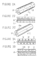
- Fig. 2A to 2C show variations of the superconducting elongated articles according to the present invention, wherein Fig. 2A is an illustrative perspective view of the article, Fig. 2B is a cross section thereof, and Fig. 2C shows an illustrative view of another embodiment of the article.
- Fig. 3A and 3B show cross sections of variations of Fig. 2.
- Fig. 4 shows another embodiment of the present invention, wherein, Fig 4A is a cross section and Fig. 4B is a plane view of the elongated article according to the present invention.
- FIG. 5 shows still another embodiment of the present invention, wherein, Fig. 5A is a cross section and Fig. 5B is a perspective view of the elongated article according to the present invention.
- Fig. 6 is an illustrative view of an apparatus for manufacturing continuously a composite having a tape-like configuration according to the present invention.
- Fig. 1A to Fig. 1J illustrate manufacturing steps for an elongated article according to the present invention.
- a metal pipe 1 having a predetermined cross sectional configuration (outer diameter of "L", and inner diameter of "l") is filled with a material ceramic powder 2, as is shown in Fig. 1B.
- the resulting metal pipe filed with the material ceramic powder is passed to wire-drawing operation which can be performed by means of roller dies 3 as is shown in Fig. 1C, or a die or a series of dies 4 shown in Fig. 1D in cross section.
- the wire-drawing may be performed by means of a swaging unit 5 as is shown in Fig. E or an extruder-type wire drawing machine (Fig. 1F shows a cross section of an extruder head).
- the metal pipe may be rolled by means of rolls 7 as is shown in Fig. 1H.
- An annealing step can be incorporated in the wire-drawing stage in order to facilitate operation of the wire-drawing. It is also preferable to seal one end or opposite ends of the metal pipe before entering into the wire-drawing operation as is shown in Fig. 1H to prevent the powder material from escaping out of the metal pipe.
- Fig. 1I illustrates a perspective view of the resulting wire-drawn product comprising an inner core obtained from the material powder 2 having a reduced diameter "l'", so that the final product which will be obtained after the subsequent sintering step hereinafter described has the same configuration as Fig. 11.
- Fig. 1J illustrates a case in which the outer pipe is removed.
- Fig. 2 shows a variation of the elongated article obtained according to the present invention, in which perforations or through holes are made in the metal pipe 11.
- fine holes 13 are cut through the metal pipe over the whole surface thereof by means of a CO 2 laser or the like.
- Fig. 2B is a cross-sectional view of the pipe shown in Fig. 2A.
- the holes 13 may be replaced by a slit 13a shown in Fig. 2C.
- the slit 13a may have a dimension of about 200 ⁇ m in width.
- the resulting superconducting wire deteriorates under an oxygen-containing atmosphere such as air, so that it is preferable to close up the holes 13 cut in the metal pipe 11.
- the holes 13 can be filled up with sealant 14 to isolate the sintered wire of superconductor 12 from the ambient atmosphere as is shown in Fig. 3A.
- This method is difficult to practice or has poor productivity, so that, in practice, it is preferable to cover the whole of the outer surface of the perforated metal pipe with a suitable air-tight cylindrical liner, for example a heat shrinkable plastic tube which is chemically stable as is shown in Fig. 3B.
- the liner may be composed of a metal layer vacuum-deposited on the whole surface of the metal pipe and more preferably may be made of low-melting point glass coated on the metal pipe to produce complete sealing.
- Fig. 4A illustrates an elongated sintered superconductor having a rectangular cross section according to an embodiment of the present invention and Fig. 4B shows a plan view thereof.
- This superconductor can be manufactured by a process including the steps of molding the superconducting material into the shape of a rectangular body 21 and then covering the molded article 21 with a metal sheath 22.
- Fig. 5 illustrates another embodiment of the elongated article having the same circular cross section as that of Fig. 1I according to the present invention, but, in this case, a superconductor 21 is covered with a sheath 24 made in the form of a net.
- Fig. 5A is a cross-sectional view and Fig. 5B is a perspective view of the resulting superconductor.
- the surface of the sheath 22 and 24 is oxidized by the oxidative treatment to produce copper oxide, so that the contents of oxygen in the sintered superconductor is not influenced or fluctuated by the oxidation of the sheath 22 or 24.
- through holes 13 are dispersed over the whole surface of the metal pipe 11 and 22, so that the sintered superconductor can communicate with an outer atmosphere. Higher contact surface between the superconductor and the surrounding atmosphere can be assured by the net-like sheath 24.
- Fig. 6 illustrates an apparatus for continuously producing an elongated article according to the present invention.
- the material ceramic powder is preferably blended with organic binder.
- the apparatus includes a continuous furnace being provided with two heating means at a binder-removing zone 112 and a sintering zone 113.
- An elongated shaped tape or wire 114 is supplied to an inlet of the binder-removing zone 112 from a coiler 115.
- the elongated article 114 unwound from the coiler 115 is fed continuously to the binder-removing zone 112 at which the elongated article 114 is heated at a temperature of 400 to 700°C to remove the binder out of the elongated article 114.
- the elongated article 114 is passed to a continuous lining station 116 which is positioned at the downstream of the binder-removing zone 112.
- the continuous lining station 116 is provided with a drum 118 for feeding a sheet 117 of metal or alloy to a guide 119 where the sheet 117 is wound around the elongated article 117.
- a seam of the wound sheet 117 is welded by means of a laser welder 120 so that the elongated article 114 is wrapped by the metal sheet 117.
- the resulting composite comprising the elongated article 114 and the covering sheet or outer sheath 117 is then passed to the sintering zone 113 where the composite is heated at a temperature of 850 to 950°C to sinter the elongated article.
- the longitudinal dimension or length of the sintering zone 113 and the velocity of advance of the composite can be adjusted in such manner that the sintering is performed completely.
- the product 121 thus obtained may be wound about a drum 122 for stock.
- the product possesses enough flexibility and self-supporting properties, since the elongated article 114 contains the binder.
- the apparatus shown in Fig. 6 permits the sintering operation to be carried out continuously at higher productivity.
- the composite comprising the elongated article and the outer sheet can be shaped or deformed into a desired configuration such as a coil or the like due to the higher flexibility end self-supporting properties, so that the sintering can be performed in the coiled configuration condition or in a condition where the coil is supported on any other conductive body.
- a desired configuration such as a coil or the like due to the higher flexibility end self-supporting properties, so that the sintering can be performed in the coiled configuration condition or in a condition where the coil is supported on any other conductive body.
- the existence of the sheath of metal or alloy also increases the bending strength.
- the material ceramic powder As the material ceramic powder, following powders may be mentioned:
- a ceramic material powder for example a compound oxide composed of at least two elements selected from a group comprising groups IIa and IIIa of the Periodic Table, one element selected from a group comprising group Va of the Periodic Table, Cu and oxygen, such as a Sr-Ca-Bi-Cu-O type compound oxide which is prepared for example by the steps comprising mixing powders of Bi 2 O 3 , SrCO 3 , CaCO 3 and CuO, drying and then compacting the powder mixture, sintering the compacted mass, and then pulverizing the sintered mass.
- a Sr-Ca-Bi-Cu-O type compound oxide which is prepared for example by the steps comprising mixing powders of Bi 2 O 3 , SrCO 3 , CaCO 3 and CuO, drying and then compacting the powder mixture, sintering the compacted mass, and then pulverizing the sintered mass.
- the material powders used in the present invention are not limited to those abovementioned.
- the material powders of ceramics are preferably previously granulated before they are filled into the metal pipe.
- the material powder is granulated into particles having an average particle size of less than 0.1 mm and then is heat-treated before being charged into the metal pipe.
- This heat-treatment corresponds to the final sintering used in the conventional procedure.
- the material powder may be further heat-treated again after the powder is compacted in the metal pipe. If the heat-treatment of the powder material result in coagulation of powders to produce large particles having an average particle size of more than 0.1 mm, the heat-treated powder may be pulverized before it is compacted in the metal pipe. In this case, conventional final heat-treatment is carried out in the powder condition having an average particle size of less than 0.1 mm.
- the resulting heat-treated powder as a whole possesses the crystal structure which exhibits superconductivity and hence there remains no portion where superconductivity is not exhibited. Furthermore, a higher packing factor or density is obtained in the metal pipe and also a higher elongation ratio of the wire is assured.
- the resulting wire obtained according to this embodiment is changed to an elongated superconducting wire having higher critical current density.
- a wire of compound oxide having the crystal structure of K 2 NiF 4 -type oxides such as a powder of [La,Ba] 2 CuO 4 or [La,Sr] 2 CuO 4 can be obtained by sintering a material powder mixture of oxides, carbonates, nitrate, sulfates or the like of the constituent elements of the compound oxide, for example, a powder mixture of La 2 O 3 , BaO 2 , SrO 2 and CuO.
- the metal pipe may be made of a metal selected from a group comprising Ag, Au, Pt, Pd, Rh, Ir, Ru, Os, Cu, Al, Fe, Ni, Cr, Ti, Mo, W and Ta and of an alloy including these metals as the base.
- the base metal it is preferable to select from among Ag, Au, platinum metals comprising Pt, Pd, Rh, Ir, Ru and Os and alloys containing them as the base metal.
- the metals of Ag, Au and platinum metals are almost inert towards the superconducting ceramic materials under heated conditions, and hence the heat-treatment operation can be carried out at a sufficiently high temperature so as to accelerate the sintering or solid-solid reaction among superconducting ceramic particles in the metal pipe to obtain a uniform elongated article.
- the metal pipe made of copper is used in place of the platinum metals, there is a possibility of reaction between the superconducting material and the copper of the metal pipe, with the results that the composition in the resulting wire will deviate or fluctuate.
- the copper pipe is apt to be oxidized, it is difficult to perform the heat-treatment at a high temperature.
- These problems may be avoidable by using a pipe of platinum metals which is chemically inactive to the ceramics filling the pipe and hence the resulting wire possesses a composition which is uniformly distributed along the longitudinal direction. Therefore, the superconducting wire whose outer metal pipe is made of platinum metal exhibits almost the same critical temperature as a bulk or mass which is produced by sintering this same material ceramic powder and shows a much higher critical current density in comparison with a wire whose outer metal pipe is made of copper.
- the plastic deformation step of the metal pipe filled with the ceramic metal powder is preferably carried out under such conditions that the cross section of the metal pipe is reduced at a dimensional reduction ratio ranging from 16% to 92%, more particularly from 20% to 90%. If the reduction ratio exceeds 92%, the material powder filling the pipe will not follow or accompany the movement of the inner surface of the metal pipe, resulting in breakage of the sintered ceramic wire inside the metal pipe at several points. On the other hand, if the reduction ratio is lower than 16%, satisfactory packing density in the metal pipe can not be expected, so that complete sintering can not be performed.
- the plastic deformation is preferably performed by the technique of wire-drawing, particularly, by means of a die or a series of dies, a roller die or a series of roller dies, or an extruder or a series of extruders.
- the plastic deformation may be carried out by forging which is preferably achieved by swaging or rolling.
- the heat-treatment of the metal pipe filled with the material ceramic powder which is performed after the plastic deformation is preferably carried out at a temperature ranging from 700 to 1,000°C which is selected as a function of the constituent elements of the ceramics.
- the superconducting powder filled in the metal pipe are kept in a condition where they are contacted with each other but are not fused to form a continuous body even after the plastic deformation.
- the heat-treatment promotes sintering or reaction among the powders to produce a uniform product.
- the temperature at which the sintering of powders of compound oxide is performed is below a melting point of the sintered body which is the upper limit and is preferably above a temperature which is 100°C lower than the melting point. If the sintering temperature is lower than the temperature which is 100°C lower than the melting point, complete sintering reaction can not be achieved and hence the resulting product will not have practical strength. On the other hand, if the sintering temperature exceeds the upper limit of the melting point, a liquid phase will be produced so that the sintered body melts or decomposes resulting in lowering the Tc.
- the metal pipe filled with the material powder is deformed or wire-drawn to target configuration
- the metal pipe is subjected to the sintering operation at a temperature where the compound oxide superconductor is not produced but which is greater than or equal to half, the reaction temperature expressed as absolute temperature, to such an extent that boundaries of the material powders diffuse each other.
- an intermediate annealing is performed, which is followed by further wire-drawing. If necessary, a combination of the wire-drawing and the intermediate annealing can be repeated the desired number of times.
- the sintered composite is subjected to the final treatment including a slow cooling at a rate of less than 50°C/min and a rapid cooling at a rate of more than 50°C to obtain the final superconductor product.
- the superconducting ceramic of Y-Ba-Cu-O type compound oxide does not exhibit the property of superconductivity if it is not sintered at a temperature of more than about 900°C and hence one constituent element of Cu in the ceramic is reduced by reaction with the metal which constitute the outer pipe, which result in deterioration of the superconductivity.
- the material powder such a powder which is prepared by pulverizing a sintered ceramic mass which itself has superconductivity and to perform the sintering operation at a temperature where no reductive reaction occur after the wire-drawing operation.
- the metal pipe containing sintered ceramic body therein is cooled slowly at a rate of less than 50°C/min.
- improvement in the property of superconductivity can be achieved by heat-treatment including a slow cooling of the sintered body at a rate of less than 50°C/min and a rapid cooling thereof at a rate of more than 50°C.
- the outer metal pipe or sheath can be removed after sintering is completed, but if necessary, the outer metal pipe may remain as it is on the outer surface of the sintered ceramic body in order to improve safety for the magnetic field and to assure a heat-transmitting path as a precaution against the case where superconductivity breaks off accidentally.
- the outer metal can be removed from the sintered body mechanically for example using grinding, or chemically for example using etching liquid such as nitric acid.
- the metal of the metal pipe may be removed during the sintering step, namely both sintering and removal of the metal are carried out simultaneously, while leaving a very thin skin layer on the surface of the sintered body.
- the thickness o:E the thin skin layer left on the surface of the sintered body is less than 500 ⁇ m, preferably less than 200 ⁇ m, so that the thin skin layer left on the surface is held on the surface even if the metal fuses during the sintering operation owing to its surface tension without dropping of the fused metal.
- the plastic deformation is performed by metal working or processing which is such that compressive stress is imparted to an article to be worked, examples being wire-drawing and forging operations, so as to cause the material powder filled in the metal pipe to be compacted.
- one adopts a sequence of steps comprising, after the plastic deformation operation such as wire-drawing for reducing the cross sectional dimension of the metal pipe complete, subjecting the deformed pipe to an intermediate annealing at a temperature where the metal pipe is annealed, further carrying out plastic deformation such as wire-drawing of the annealed pipe, and then subjecting the resulting pipe to the final heat-treatment to sinter the material ceramic powder filled in the metal pipe.
- the metal pipe may be removed after the intermediate annealing and the first annealing but before the final sintering of the material ceramic powder in order to prevent undesirable reaction between the ceramic powder and the metal of the metal pipe at a high sintering temperature.
- the second annealing advantageously provides enough strength which can resist against external force exerted on the annealed article and/or imparts a desired configuration to the annealed body, before it is passed to, and during it is maintained in, the final sintering furnace in which the annealed article is sintered with no outer metal pipe.
- the combination of the wire-drawing and the intermediate annealing can be repeated a desired number of times to increase the dimensional reduction ratio in the cross sectional direction with no wire breakage, and hence the resulting wire shows a fine diameter and higher strength.
- the intermediate annealing is performed in the temperature range where the metal pipe is annealed but ceramic powder is not sintered.
- the intermediate annealing following the wire-drawing is performed in the temperature range where the metal pipe is annealed but ceramic powder is not sintered, a higher dimensional reduction ratio can be achieved to obtain a fine ceramic wire having satisfactory deflection strength with no breakage.
- the intermediate annealing can be performed at a suitable temperature which is selected as a function of the kind of metal of the metal pipe and components and composition of the ceramic powder.
- through holes which pass through a wall of the metal pipe are made after plastic deformation is completed, so that the material ceramic powder filled in the perforated metal pipe is sintered in an open condition.
- the wall of the metal pipe of the wire is perforated by means of laser, electron beam or a microdrill or the like, so as to permit passage of gas, particularly oxygen-containing gas through the perforations or holes.
- gas particularly oxygen-containing gas
- the material ceramic powder is sintered under a closed or sealed condition in the outer metal pipe in the sintering stage, so that oxygen deficiency in the compound oxide is too great to obtain a product having superior superconductivity. Therefore, it is preferable to make through holes in the wall and to carry out the sintering of the metal pipe in an atmosphere containing oxygen gas to supply a proper amount of oxygen to the compound oxide in the metal pipe.
- satisfactory oxygen can be supplied through the through holes or a slit made in the outer metal layer, so that the resulting sintered body of compound oxide possess a crystal structure of a so to say quasi-perovskite type crystal structure such as an orthorhombic structure or the like for which there is a higher possibility of producing Cooper pairs.
- the through holes or slit are preferably closed by filling them with sealing material or by covering the whole outer surface of the metal pipe with another metal sheath or covering in order to protect the compound oxide from deterioration due to attack by surrounding humid gas.
- the material powder was compacted in an iron pipe having an outer diameter of 5 mm, an inner diameter of 4 mm and a length of 1 m and opposite ends of the pipe were sealed.
- the wire-drawing was ceased when the outer diameter reduced to a value of 1.5 mm. And then, the pipe was subjected to a series of operations comprising an intermediate annealing at 750°C for 25 hours, a plurality of wire-drawing operations each of which was carried out at a cross sectional reduction ratio of 18% per pass so that the pipe was reduced to 0.6 mm in diameter, and sintering being carried out at 930°C for 3 hours.
- the measured value of the critical temperature (Tc) was 38°K.
Description
- The present invention relates to a process for manufacturing an elongated article made of sintered ceramic material possessing superconductivity.
- Particularly, it relates to a process for manufacturing a superconducting wire made of sintered ceramic of compound oxide which is applicable for producing superconducting coils or the like.
- More particularly, the present invention relates to a process for manufacturing a superconducting wire made of sintered ceramic of compound oxide having a higher critical current density and a higher superconductivity critical transition temperature.
- Superconductivity is a phenomenon in which electrical resistance becomes zero and hence can be utilized to realize power cables and a variety of devices and apparatus which are requested to reduce consumption of electrical energy and several ideas for its applications which utilize the phenomenon of superconductivity have been proposed.
- In fact, superconductivity is applicable in a variety of industrial fields, for example in the field of electrical power supply such as fusion power, MHD power generation, power transmission, or electric power reservation; in the field of transportation such as magnetic levitation trains, magnetic propulsion of ships; in the medical field such as in a high-energy beam radiation unit; in the field of science such as NMR or high-energy physics; or in the field of sensors or detectors for sensing very weak magnetic fields, microwave or radiant radiation or the like as well as in the field of electronics such as Josephson Junction devices and high-speed computers with reduced energy consumption.
- However, their actual usage have been restricted because the phenomenon of superconductivity can be observed only at very low cryogenic temperatures. Among known superconducting materials, a group of materials having so-called A-15 structure show rather higher Tc (critical temperature of superconductivity) than others, but even the top record of Tc in the case of Nb3Ge which showed the highest Tc could not exceed 23.2°K as most.
- This means that liquidized helium (boiling point of 4.2°K) is the only cryogen that can provide such a very low temperature of Tc. However, helium is not only a limited, costly resource but also requires a large-scale system for liquefaction. Therefore, it is desired to find another superconducting materials having much higher Tc. But research has found no material which exceeded the above-mentioned Tc during the past ten years.
- It is known that certain ceramic materials of compound oxides exhibit the property of superconductivity. For example, U.S. patent No. 3,932,315 discloses Ba-Pb-Bi-type compound oxide which shows superconductivity. This type of superconductor, however, possess a rather low transition temperature of lower than 13°K and hence usage of liquidized helium (boiling point of 4.2°K) as the cryogen is indispensable to realize superconductivity.
- The possibility of the existence of a new type of superconducting materials having much higher Tc was revealed by Bednorz and Muller who discovered a new oxide type superconductor in 1986 [Z. Phys. B64 (1986) p.189]. However this document neither describes nor mentions the use of such an oxide material to produce a superconducting wire thereof.
- This new oxide type superconducting material is La, Ba2CuO4 or La, Sr2CuO4 which are so-called K2NiF4-type oxides having a crystal structure that is similar to perovskite-type superconducting oxides which were known in the past (for example, BaPb1-xBixO3 disclosed in U.S. Patent No. 3,932,315). The K2NiF4-type oxides show such higher Tc at round about 30°K which is very much higher than that of known superconducting materials.
- As the compound oxide type superconductors consisting of oxides of elements of IIa and IIIa groups in the Periodic Table, we can be mention those of, so to say, quasi-Perovskite structure which can be considered to have a crystal structure that is similar to Perovskite-type oxides and includes an orthorhombically distorted perovskite or a distorted oxygen-deficient perovskite such as Ba2YCu3O7-δ in addition to the abovementioned K2NiF4-type oxide such as [La,Ba]2CuO4 or [La,Sr]2CuO4. Since these superconducting materials show very high Tc of 30 to 90°K, it becomes possible to use liquidized hydrogen (b.p. = 20.4°K) or liquidized neon (b.p. = 27.3°K) as a cryogen for realizing the superconductivity in practice. Particularly, hydrogen is an inexhaustable resource but has the danger of explosion.
- However, the above mentioned new type superconducting materials which have just come to light have been studied and developed only in a form of sintered bodies as a bulk product produced from powders but for which no attempt has been made them into a wire form. The reason is that the new type superconductors are ceramic materials of compound oxide which do not possess high plasticity or processability when compared with well-known metal type superconducting materials such as Ni-Ti alloy, and therefore they can not, or can only with difficulty, be shaped or deformed into an elongated article such as a wire by a conventional technique such as wire-drawing technique in which superconducting metal is drawn directly, or embedded in copper, to a wire form.
- There is proposed in laid-open Japanese patent No. 61-131,307 and also in IEEE Transactions on Magnetics, vol. MAG-19, No. 3, May 3, 1983, p.402, a method for manufacturing a superconducting wire from a metal type superconducting material which is apt to be oxidized and very fragile such as PbMo0.35S8, or PbMo6S8 respectively, comprising charging the material powder in a metal shell, extruding the metal shell filled with the material powder at higher than 1,000°C, and then drawing the extruded composite. This metal working technique, to be more specific, can not be applied directly to ceramic material consisting of compound oxide, because the compound oxide type superconducting materials can not exhibit the superconductivity if the specific or predetermined crystal structure is not realized. In other words, a superconducting wire having higher critical temperature and higher critical current density and which is useable in actual applications can not be obtained outside predetermined optimum conditions. In particular, if the shell is not selected from suitable materials, the resulting compound oxide will be reduced due to chemical reaction with the metal of the shell, resulting in poor or inferior superconductivity properties.
- In the field of ceramic molding, it has been the general practice for manufacturing an elongated article such as wires or rods to add an organic binder to the material powder of ceramic in order to facilitate shaping or molding of the powder material. Thus, a mixture of the powder material and the organic binder is shaped into a rod by means of an extruder or a press machine and then the shaped rod is passed directly, or via a trimming or cutting stage, to an intermediate sintering stage to remove the organic binder before it is fed to the final sintering stage.
- The combination of the abovementioned press-molding and trimming or cutting operations gives rise to loss of much expensive ceramics material, so that not only economy of material is low but also a dimensional ratio of longitudinal direction to cross-sectional direction of the rod can not be increased. Therefore, this process can not be used in practice.
- The extrusion technique is much better than the press-molding technique as regards economy of material and productivity, but requires great quantities of organic binder added to the powder material. This organic binder is difficult to remove completely during the intermediate sintering stage and hence remains in the final sintered article, being a cause of defects of the product which will lower its strength and flexibility. Therefore, it is difficult to manufacture a fine rod of ceramics having higher dimensional ratios of longitudinal direction to cross sectional direction according to the extrusion technique.
- DE-B-12 57 436 discloses the fabrication of a superconducting wire by a powder metallurgical technique. According to the method, a metal pipe is filled with Nb3Sn. The pipe is reduced in diametern and the reduced pipe is then heat treated at a temperature sufficient to make the powder filled in the pipe superconducting.
- In order to realize a reliable and practical superconducting structure, it is indispensable that the structure possesses sufficient strength and tenacity to endure bending forces during usage and also has as fine a cross-sectional dimension as possible so that it can transmit electrical current at higher critical current density and at higher critical temperature.
- Therefore, an object of the present invention is to provide a process for manufacturing a superconducting wire of sintered ceramic having a sufficient length to be used in practical applications, namely having a higher dimensional ratio of longitudinal direction to cross sectional direction, without using organic binder which is causative of lowering the strength and tenacity of the product.
- Another object of the present invention is to provide a process for manufacturing a fine superconducting wire of compound oxide type sintered ceramic having higher resistance to breakage, even if the diameter of the wire is reduced greatly in other words, under higher cross section dimensional reduction ratios.
- Still another object of the present invention is to provide a process for manufacturing a fine superconducting wire of compound oxide type sintered ceramic having higher critical current density and higher critical temperature.
- The present invention provides a process for manufacturing a superconducting elongated article, according to
claim 1. - The elongated articles which can be manufactured by the process according to the present invention include rods, wires, strands, tapes, bands, or any other articles whose dimensional ratio of the elongated direction to the cross sectional direction is more than 30, the cross section of the article not being limited to a circle but may have any configuration such as a rectangular shape.
- The material powder of ceramic consisting of compound oxide having superconductivity includes any compound oxide which exhibits superconductivity after the heat-treatment according to the present invention.
- Generally speaking, the material ceramic powder which can be used in the process of the present invention may have the general formula: AaBbCc, in which "A" stands for at least one element selected from a group comprising IIa and IIIa of the Periodic Table, "B" stands for at least one element selected from a group comprising Ia, IIa and IIIa of the Periodic Table, "C" stands for at least one element selected from a group comprising oxygen, carbon, nitrogen, fluorine and sulfur, and "a", "b" and "c" stand for atom ratios of the elements "A", "B" and "C". They preferably satisfy the following equation:
- The ceramic powder material is preferably a powder mixture containing oxides of such metals that possess higher oxygen potential for producing the oxide than that of copper.
- Among superconducting ceramics, we can be mention those that contain at least two elements selected from groups Ia, IIa and IIIa of the Periodic Table as "A", at least copper as "B", and oxygen as "C", for example, Y-Ba-Cu-O type ceramics, Y-Sr-Cu-O type ceramics, La-Sr-Cu-O type ceramics and La-Ba-Cu-O type ceramics.
- The ceramic material powder may be compound oxides having the crystal structure of K2NiF4-type oxides, such as [La,Ba]2CuO4 or [La,Sr]2CuO4.
- Additionally, the material ceramic powder may be compound oxides having Perovskite-type crystal structure exhibiting superconductivity having the general formula:
- It is also preferable to use a ceramic material powder which is prepared by steps comprising mixing powders of Bi2O3 SrCO3, CaCO3 and CuO, drying and then compacting the powder mixture, sintering the compacted mass, and then pulverizing the sintered mass.
- The material powders of ceramics are preferably previously granulated before they are filled into the metal pipe.
- The metal pipe may be selected from a group comprising metals of Ag, Au, Pt, Pd, Rh, Ir, Ru, Os, Cu, Al, Fe, Ni, Cr, Ti, Mo, W and Ta and alloys including these metals as their base.
- The heat-treatment may be carried out over a temperature range of from 700 to 1,000°C.
- The plastic deformation of the metal pipe filled with the ceramic material powder may be performed in such manner that the cross section of the metal pipe is reduced at a dimensional reduction ratio ranging from 16% to 92%. The operation of the plastic deformation may be carried out by wire-drawing which is performed by means of dies, roller dies, or extruder.
- The plastic deformation may be performed by forging, for example by means of a swaging unit or rolls.
- It is also preferable to cool the metal pipe containing the sintered ceramic material powder therein slowly at a rate of less than 50°C/min, after the heat-treatment is completed.
- Now, an apparatus which can be used to realize the abovementioned process according to the present invention will be described with reference to the attached drawings which are not limitative of the present invention.
- Fig. 1A to 1J illustrate a series of steps for manufacturing a superconducting elongated article according to the present invention.
- Fig. 2A to 2C show variations of the superconducting elongated articles according to the present invention, wherein Fig. 2A is an illustrative perspective view of the article, Fig. 2B is a cross section thereof, and Fig. 2C shows an illustrative view of another embodiment of the article.
- Fig. 3A and 3B show cross sections of variations of Fig. 2.
- Fig. 4 shows another embodiment of the present invention, wherein, Fig 4A is a cross section and Fig. 4B is a plane view of the elongated article according to the present invention.
- Fig. 5 shows still another embodiment of the present invention, wherein, Fig. 5A is a cross section and Fig. 5B is a perspective view of the elongated article according to the present invention.
- Fig. 6 is an illustrative view of an apparatus for manufacturing continuously a composite having a tape-like configuration according to the present invention.
- Referring to Fig. 1, the Fig. 1A to Fig. 1J illustrate manufacturing steps for an elongated article according to the present invention.
- First, a
metal pipe 1 having a predetermined cross sectional configuration (outer diameter of "L", and inner diameter of "l") is filled with a materialceramic powder 2, as is shown in Fig. 1B. - Then, the resulting metal pipe filed with the material ceramic powder is passed to wire-drawing operation which can be performed by means of roller dies 3 as is shown in Fig. 1C, or a die or a series of dies 4 shown in Fig. 1D in cross section. The wire-drawing may be performed by means of a
swaging unit 5 as is shown in Fig. E or an extruder-type wire drawing machine (Fig. 1F shows a cross section of an extruder head). In the case of an elongated article having a rectangular cross section, the metal pipe may be rolled by means of rolls 7 as is shown in Fig. 1H. - An annealing step can be incorporated in the wire-drawing stage in order to facilitate operation of the wire-drawing. It is also preferable to seal one end or opposite ends of the metal pipe before entering into the wire-drawing operation as is shown in Fig. 1H to prevent the powder material from escaping out of the metal pipe.
- Fig. 1I illustrates a perspective view of the resulting wire-drawn product comprising an inner core obtained from the
material powder 2 having a reduced diameter "l'", so that the final product which will be obtained after the subsequent sintering step hereinafter described has the same configuration as Fig. 11. - Fig. 1J illustrates a case in which the outer pipe is removed.
- Fig. 2 shows a variation of the elongated article obtained according to the present invention, in which perforations or through holes are made in the
metal pipe 11. In an embodiment shown in the perspective view of Fig. 2A,fine holes 13 are cut through the metal pipe over the whole surface thereof by means of a CO2 laser or the like. Fig. 2B is a cross-sectional view of the pipe shown in Fig. 2A. Theholes 13 may be replaced by a slit 13a shown in Fig. 2C. The slit 13a may have a dimension of about 200 µm in width. - It is known that the resulting superconducting wire deteriorates under an oxygen-containing atmosphere such as air, so that it is preferable to close up the
holes 13 cut in themetal pipe 11. For this purpose, theholes 13 can be filled up withsealant 14 to isolate the sintered wire ofsuperconductor 12 from the ambient atmosphere as is shown in Fig. 3A. This method, however, is difficult to practice or has poor productivity, so that, in practice, it is preferable to cover the whole of the outer surface of the perforated metal pipe with a suitable air-tight cylindrical liner, for example a heat shrinkable plastic tube which is chemically stable as is shown in Fig. 3B. The liner may be composed of a metal layer vacuum-deposited on the whole surface of the metal pipe and more preferably may be made of low-melting point glass coated on the metal pipe to produce complete sealing. - Fig. 4A illustrates an elongated sintered superconductor having a rectangular cross section according to an embodiment of the present invention and Fig. 4B shows a plan view thereof. This superconductor can be manufactured by a process including the steps of molding the superconducting material into the shape of a
rectangular body 21 and then covering the moldedarticle 21 with ametal sheath 22. - Fig. 5 illustrates another embodiment of the elongated article having the same circular cross section as that of Fig. 1I according to the present invention, but, in this case, a
superconductor 21 is covered with asheath 24 made in the form of a net. Fig. 5A is a cross-sectional view and Fig. 5B is a perspective view of the resulting superconductor. - The abovementioned variation can be adopted to a variety of applications. The presence of the abovementioned porous outer sheath or shell provides the following advantages:
- At first, the surface of the
sheath sheath holes 13 are dispersed over the whole surface of themetal pipe like sheath 24. - Fig. 6 illustrates an apparatus for continuously producing an elongated article according to the present invention. In this case, the material ceramic powder is preferably blended with organic binder.
- The apparatus includes a continuous furnace being provided with two heating means at a binder-removing
zone 112 and asintering zone 113. An elongated shaped tape orwire 114 is supplied to an inlet of the binder-removingzone 112 from acoiler 115. Theelongated article 114 unwound from thecoiler 115 is fed continuously to the binder-removingzone 112 at which theelongated article 114 is heated at a temperature of 400 to 700°C to remove the binder out of theelongated article 114. - After the binder-removing
zone 112, theelongated article 114 is passed to acontinuous lining station 116 which is positioned at the downstream of the binder-removingzone 112. Thecontinuous lining station 116 is provided with adrum 118 for feeding a sheet 117 of metal or alloy to a guide 119 where the sheet 117 is wound around the elongated article 117. A seam of the wound sheet 117 is welded by means of alaser welder 120 so that theelongated article 114 is wrapped by the metal sheet 117. - The resulting composite comprising the
elongated article 114 and the covering sheet or outer sheath 117 is then passed to thesintering zone 113 where the composite is heated at a temperature of 850 to 950°C to sinter the elongated article. The longitudinal dimension or length of thesintering zone 113 and the velocity of advance of the composite can be adjusted in such manner that the sintering is performed completely. - The
product 121 thus obtained may be wound about adrum 122 for stock. In this embodiment, the product possesses enough flexibility and self-supporting properties, since theelongated article 114 contains the binder. The apparatus shown in Fig. 6 permits the sintering operation to be carried out continuously at higher productivity. - According to a variation of the present invention, the composite comprising the elongated article and the outer sheet can be shaped or deformed into a desired configuration such as a coil or the like due to the higher flexibility end self-supporting properties, so that the sintering can be performed in the coiled configuration condition or in a condition where the coil is supported on any other conductive body. The existence of the sheath of metal or alloy also increases the bending strength.
- In a preferable embodiment according to the present invention, as the material ceramic powder, following powders may be mentioned:
- (1) Ceramic powder containing compound oxides having the crystal structure of K2NiF4-type oxides having superconducting property, particularly powders of [La,Ba]2CuO4 or [La,Sr]2CuO4.
- (2) Compound oxides having Perovskite-type crystal structure
exhibiting superconductivity having the general formula:
-
- It is possible to use another type ceramic material powders for example a compound oxide composed of at least two elements selected from a group comprising groups IIa and IIIa of the Periodic Table, one element selected from a group comprising group Va of the Periodic Table, Cu and oxygen, such as a Sr-Ca-Bi-Cu-O type compound oxide which is prepared for example by the steps comprising mixing powders of Bi2O3, SrCO3, CaCO3 and CuO, drying and then compacting the powder mixture, sintering the compacted mass, and then pulverizing the sintered mass.
- The material powders used in the present invention are not limited to those abovementioned.
- The material powders of ceramics are preferably previously granulated before they are filled into the metal pipe. When the material powder can not be compacted into the metal pipe at a higher packaging density, it is desirable to granulate the material powder previously to facilitate charging operation into the metal pipe and to obtain a higher packing density.
- According to a preferred embodiment, the material powder is granulated into particles having an average particle size of less than 0.1 mm and then is heat-treated before being charged into the metal pipe. This heat-treatment corresponds to the final sintering used in the conventional procedure. In this case, if necessary, the material powder may be further heat-treated again after the powder is compacted in the metal pipe. If the heat-treatment of the powder material result in coagulation of powders to produce large particles having an average particle size of more than 0.1 mm, the heat-treated powder may be pulverized before it is compacted in the metal pipe. In this case, conventional final heat-treatment is carried out in the powder condition having an average particle size of less than 0.1 mm. Therefore, the resulting heat-treated powder as a whole possesses the crystal structure which exhibits superconductivity and hence there remains no portion where superconductivity is not exhibited. Furthermore, a higher packing factor or density is obtained in the metal pipe and also a higher elongation ratio of the wire is assured. In conclusion, the resulting wire obtained according to this embodiment is changed to an elongated superconducting wire having higher critical current density.
- In operation, a wire of compound oxide having the crystal structure of K2NiF4-type oxides such as a powder of [La,Ba]2CuO4 or [La,Sr]2CuO4 can be obtained by sintering a material powder mixture of oxides, carbonates, nitrate, sulfates or the like of the constituent elements of the compound oxide, for example, a powder mixture of La2O3, BaO2, SrO2 and CuO.
- The metal pipe may be made of a metal selected from a group comprising Ag, Au, Pt, Pd, Rh, Ir, Ru, Os, Cu, Al, Fe, Ni, Cr, Ti, Mo, W and Ta and of an alloy including these metals as the base.
- In particular, it is preferable to select from among Ag, Au, platinum metals comprising Pt, Pd, Rh, Ir, Ru and Os and alloys containing them as the base metal. The metals of Ag, Au and platinum metals are almost inert towards the superconducting ceramic materials under heated conditions, and hence the heat-treatment operation can be carried out at a sufficiently high temperature so as to accelerate the sintering or solid-solid reaction among superconducting ceramic particles in the metal pipe to obtain a uniform elongated article. When the metal pipe made of copper is used in place of the platinum metals, there is a possibility of reaction between the superconducting material and the copper of the metal pipe, with the results that the composition in the resulting wire will deviate or fluctuate. Moreover, since the copper pipe is apt to be oxidized, it is difficult to perform the heat-treatment at a high temperature. These problems may be avoidable by using a pipe of platinum metals which is chemically inactive to the ceramics filling the pipe and hence the resulting wire possesses a composition which is uniformly distributed along the longitudinal direction. Therefore, the superconducting wire whose outer metal pipe is made of platinum metal exhibits almost the same critical temperature as a bulk or mass which is produced by sintering this same material ceramic powder and shows a much higher critical current density in comparison with a wire whose outer metal pipe is made of copper.
- According to the present invention, it is also possible to arrange another metal such as copper, copper alloy or stainless steel around the outer metal pipe. Such additional metal layer will increase the flexibility of the resulting wire which is obtained by plastic deformation.
- The plastic deformation step of the metal pipe filled with the ceramic metal powder is preferably carried out under such conditions that the cross section of the metal pipe is reduced at a dimensional reduction ratio ranging from 16% to 92%, more particularly from 20% to 90%. If the reduction ratio exceeds 92%, the material powder filling the pipe will not follow or accompany the movement of the inner surface of the metal pipe, resulting in breakage of the sintered ceramic wire inside the metal pipe at several points. On the other hand, if the reduction ratio is lower than 16%, satisfactory packing density in the metal pipe can not be expected, so that complete sintering can not be performed.
- The plastic deformation is preferably performed by the technique of wire-drawing, particularly, by means of a die or a series of dies, a roller die or a series of roller dies, or an extruder or a series of extruders. The plastic deformation may be carried out by forging which is preferably achieved by swaging or rolling.
- It is also possible to combine more than two operations of the abovementioned plastic deformations of extrusion, rolling, swaging and other wire drawing. It is also possible to shape the deformed wire into a desired configuration such as a shape of a coil which is applicable to a superconducting magnet or the like before the coil is heat-treated.
- The heat-treatment of the metal pipe filled with the material ceramic powder which is performed after the plastic deformation is preferably carried out at a temperature ranging from 700 to 1,000°C which is selected as a function of the constituent elements of the ceramics. Thus, the superconducting powder filled in the metal pipe are kept in a condition where they are contacted with each other but are not fused to form a continuous body even after the plastic deformation. The heat-treatment promotes sintering or reaction among the powders to produce a uniform product.
- Generally speaking, the temperature at which the sintering of powders of compound oxide is performed is below a melting point of the sintered body which is the upper limit and is preferably above a temperature which is 100°C lower than the melting point. If the sintering temperature is lower than the temperature which is 100°C lower than the melting point, complete sintering reaction can not be achieved and hence the resulting product will not have practical strength. On the other hand, if the sintering temperature exceeds the upper limit of the melting point, a liquid phase will be produced so that the sintered body melts or decomposes resulting in lowering the Tc.
- According to one embodiment, after the metal pipe filled with the material powder is deformed or wire-drawn to target configuration, the metal pipe is subjected to the sintering operation at a temperature where the compound oxide superconductor is not produced but which is greater than or equal to half, the reaction temperature expressed as absolute temperature, to such an extent that boundaries of the material powders diffuse each other. After the wire-drawing step, an intermediate annealing is performed, which is followed by further wire-drawing. If necessary, a combination of the wire-drawing and the intermediate annealing can be repeated the desired number of times. After this, the sintered composite is subjected to the final treatment including a slow cooling at a rate of less than 50°C/min and a rapid cooling at a rate of more than 50°C to obtain the final superconductor product. The reasons why the above-mentioned procedure is preferable results from the fact that the superconducting ceramic of Y-Ba-Cu-O type compound oxide does not exhibit the property of superconductivity if it is not sintered at a temperature of more than about 900°C and hence one constituent element of Cu in the ceramic is reduced by reaction with the metal which constitute the outer pipe, which result in deterioration of the superconductivity. To solve this problem, it is preferable to use, as the material powder, such a powder which is prepared by pulverizing a sintered ceramic mass which itself has superconductivity and to perform the sintering operation at a temperature where no reductive reaction occur after the wire-drawing operation.
- It is also preferable that, after the sintering or heat-treatment is completed, the metal pipe containing sintered ceramic body therein is cooled slowly at a rate of less than 50°C/min. When the process according to the present invention is applied to a sintered ceramic wire of Y-Ba-Cu-O type compound oxide or the like, improvement in the property of superconductivity can be achieved by heat-treatment including a slow cooling of the sintered body at a rate of less than 50°C/min and a rapid cooling thereof at a rate of more than 50°C.
- The outer metal pipe or sheath can be removed after sintering is completed, but if necessary, the outer metal pipe may remain as it is on the outer surface of the sintered ceramic body in order to improve safety for the magnetic field and to assure a heat-transmitting path as a precaution against the case where superconductivity breaks off accidentally. On the other hand, when inherent properties of a sintered ceramic body, such as resistance to chemicals and resistance to abrasion are required, it is preferable to remove the metal pipe off the sintered body (Fig. 1J). The outer metal can be removed from the sintered body mechanically for example using grinding, or chemically for example using etching liquid such as nitric acid.
- In a variation of the process according to the present invention, almost all the metal of the metal pipe may be removed during the sintering step, namely both sintering and removal of the metal are carried out simultaneously, while leaving a very thin skin layer on the surface of the sintered body. The thickness o:E the thin skin layer left on the surface of the sintered body is less than 500 µm, preferably less than 200 µm, so that the thin skin layer left on the surface is held on the surface even if the metal fuses during the sintering operation owing to its surface tension without dropping of the fused metal.
- It is preferable that the plastic deformation is performed by metal working or processing which is such that compressive stress is imparted to an article to be worked, examples being wire-drawing and forging operations, so as to cause the material powder filled in the metal pipe to be compacted.
- According to the invention one adopts a sequence of steps comprising, after the plastic deformation operation such as wire-drawing for reducing the cross sectional dimension of the metal pipe complete, subjecting the deformed pipe to an intermediate annealing at a temperature where the metal pipe is annealed, further carrying out plastic deformation such as wire-drawing of the annealed pipe, and then subjecting the resulting pipe to the final heat-treatment to sinter the material ceramic powder filled in the metal pipe. In this case, the metal pipe may be removed after the intermediate annealing and the first annealing but before the final sintering of the material ceramic powder in order to prevent undesirable reaction between the ceramic powder and the metal of the metal pipe at a high sintering temperature. It is also possible to repeat another intermediate annealing after the first wire-drawing following the first intermediate annealing, so that, after then, the metal pipe is removed after the repeated second intermediate annealing before the final sintering. According to this sequence of operations comprising the first annealing, wire-drawing and the second annealing, the second annealing advantageously provides enough strength which can resist against external force exerted on the annealed article and/or imparts a desired configuration to the annealed body, before it is passed to, and during it is maintained in, the final sintering furnace in which the annealed article is sintered with no outer metal pipe. The combination of the wire-drawing and the intermediate annealing can be repeated a desired number of times to increase the dimensional reduction ratio in the cross sectional direction with no wire breakage, and hence the resulting wire shows a fine diameter and higher strength.
- The intermediate annealing is performed in the temperature range where the metal pipe is annealed but ceramic powder is not sintered.
- Since the intermediate annealing following the wire-drawing is performed in the temperature range where the metal pipe is annealed but ceramic powder is not sintered, a higher dimensional reduction ratio can be achieved to obtain a fine ceramic wire having satisfactory deflection strength with no breakage. The intermediate annealing can be performed at a suitable temperature which is selected as a function of the kind of metal of the metal pipe and components and composition of the ceramic powder.
- It is also possible to add a cold working step before and/or after the hot working step. Furthermore, it is also possible to repeat the series of steps including the above-mentioned hot working and sintering steps several times.
- According to a special variation of the process of the present invention, through holes which pass through a wall of the metal pipe are made after plastic deformation is completed, so that the material ceramic powder filled in the perforated metal pipe is sintered in an open condition.
- In this variation, after the wire drawing, the wall of the metal pipe of the wire is perforated by means of laser, electron beam or a microdrill or the like, so as to permit passage of gas, particularly oxygen-containing gas through the perforations or holes. If the metal pipe is not perforated, the material ceramic powder is sintered under a closed or sealed condition in the outer metal pipe in the sintering stage, so that oxygen deficiency in the compound oxide is too great to obtain a product having superior superconductivity. Therefore, it is preferable to make through holes in the wall and to carry out the sintering of the metal pipe in an atmosphere containing oxygen gas to supply a proper amount of oxygen to the compound oxide in the metal pipe. It is the general property of superconducting compound oxides that the superconductivity is influenced by the oxygen deficiency in the crystal structure. In other words, the oxygen deficiency as well as the crystal structure of the resulting sintered wire are keys to the superconductivity. Therefore, it is important to adjust the atomic ratios of elements so as to satisfy the abovementioned ranges of elements defined in connection with the general formula: (α 1-x, βx) γy Oz as well as to fulfill the abovementioned procedure according to the present invention in order to adjust the oxygen contents defined by the general formula. Otherwise, the value of Tc can not be improved owing to a different crystal structure and improper oxygen deficiency.
- According to the abovementioned special variant, satisfactory oxygen can be supplied through the through holes or a slit made in the outer metal layer, so that the resulting sintered body of compound oxide possess a crystal structure of a so to say quasi-perovskite type crystal structure such as an orthorhombic structure or the like for which there is a higher possibility of producing Cooper pairs.
- The through holes or slit are preferably closed by filling them with sealing material or by covering the whole outer surface of the metal pipe with another metal sheath or covering in order to protect the compound oxide from deterioration due to attack by surrounding humid gas.
- It is also preferable to increase the partial pressure of oxygen gas during the sintering stage in order to promote penetration of oxygen gas through the holes or slits.
- Now, the process according to the present invention will be described with reference to illustrative Examples, but the scope of the present invention should not be limited thereto.
- 20.8% by weight of commercially available Y2O3 powder, 54.7% by weight of commercially available BaCO3 and 24.5% by weight of commercially available CuO were mixed in an attrition mill in the wet state and then dried. The dried powder was sintered at 880°C in air for 24 hours. The sintered body was pulverized and passed through a sieve to obtain powder of under 100 mesh. The steps including sintering, pulverization and screening were repeated three times.
- After granulation treatment, the material powder was compacted in an iron pipe having an outer diameter of 5 mm, an inner diameter of 4 mm and a length of 1 m and opposite ends of the pipe were sealed.
- When the pipe filled with the material powder was subjected to a series of wire-drawing operations in such a manner that its outer diameter was reduced in a cross sectional reduction ratio of 19% per pass, the pipe broke when the outer diameter thereof was reduced to 1.2 mm.
- Therefore, the wire-drawing was ceased when the outer diameter reduced to a value of 1.5 mm. And then, the pipe was subjected to a series of operations comprising an intermediate annealing at 750°C for 25 hours, a plurality of wire-drawing operations each of which was carried out at a cross sectional reduction ratio of 18% per pass so that the pipe was reduced to 0.6 mm in diameter, and sintering being carried out at 930°C for 3 hours.
- The measured value of the critical temperature (Tc) was 38°K.
Claims (16)
- A process for manufacturing a superconducting elongated article, comprising the steps of filling a metal pipe with a material powder, subjecting the said metal pipe filled with said material powder to cold plastic deformation to reduce the cross section of said metal pipe, and heating the deformed metal pipe to sinter said material powder,
characterized in that the said metal pipe is filled with a ceramic material powder consisting of a compound oxide having superconductivity,
in that the deformed metal pipe is subjected to an intermediate annealing at such a temperature that said metal pipe is annealed but said material powder is not sintered,
and in that the pipe is subjected to another plastic deformation before said heating step. - The process set forth in claim 1, characterized in that, after said ceramic powder is sintered, said metal pipe containing the sintered material powder therein is cooled slowly at a rate of less than 50°C/min.
- The process set forth in claim 1 or 2, characterized in that said material powder of ceramic is a compound oxide having a K2NiF4-type crystal structure.
- The process set forth in claim 3, characterized in that said compound oxide is (La,M)2CuO4 in which M stands for Ba or Sr.
- The process set forth in any one of claims 1 to 3, characterized in that said material powder of ceramic is a compound oxide having a Perovskite-type crystal structure exhibiting superconductivity having the general formula:
- The process set forth in claim 5, characterized in that said α is Ba, and β is Y.
- The process set forth in claim 5, characterized in that said material powder of ceramic is prepared by the steps of mixing powders of Bi2O3, SrCO3, CaCO3 and CuO, drying and then compacting the powder mixture, sintering the compacted mass, and then pulverizing the sintered mass.
- The process set forth in any one of claims 1 to 7, characterized in that said metal pipe is made of a metal selected from a group comprising Ag, Au, Pt, Pd, Rh, Ir, Ru, Os, Cu, Al, Fe, Ni, Cr, Ti, Mo, W and Ta and alloys of these metals.
- The process set forth in any one of claims 1 to 8, characterized in that said cold plastic deformation of the metal pipe filled with the ceramic material powder is effected in such a manner that the cross section of said metal pipe is reduced at a dimensional reduction ratio ranging from 16% to 92%.
- The process set forth in any one of claims 1 to 9, characterized in that said cold plastic deformation is carried out by wire-drawing.
- The process set forth in claim 10, characterized in that said wire-drawing is performed by at least one means selected from the group consisting of dies, roller dies and an extruder.
- The process set forth in any one of claims 1 to 9, characterized in that cold plastic deformation is carried out by forging.
- The process set forth in claim 12, characterized in that said forging is performed by means of a swaging unit or rolls.
- The process set forth in any one of claims 1 to 13, characterized in that said material powder of ceramic is granulated before said material powder is filled into said metal pipe.
- The process set forth in any one of claims 1 to 14, characterized in that openings passing through a wall of said metal pipe are made after said cold plastic deformation but before heating.
- The process set forth in any one of claims 1 to 15, characterized in that said metal pipe is removed from said sintered ceramic material powder after the cooling has been complete.
Applications Claiming Priority (34)
| Application Number | Priority Date | Filing Date | Title |
|---|---|---|---|
| JP2522487 | 1987-02-05 | ||
| JP25224/87 | 1987-02-05 | ||
| JP2522487 | 1987-02-05 | ||
| JP66992/87 | 1987-03-20 | ||
| JP6699287 | 1987-03-20 | ||
| JP6699287 | 1987-03-20 | ||
| JP7794187 | 1987-03-31 | ||
| JP77941/87 | 1987-03-31 | ||
| JP7794187 | 1987-03-31 | ||
| JP9042687 | 1987-04-13 | ||
| JP90426/87 | 1987-04-13 | ||
| JP9042687 | 1987-04-13 | ||
| JP93974/87 | 1987-04-16 | ||
| JP9397387 | 1987-04-16 | ||
| JP9397487 | 1987-04-16 | ||
| JP9397387 | 1987-04-16 | ||
| JP93973/87 | 1987-04-16 | ||
| JP9397487 | 1987-04-16 | ||
| JP9588287 | 1987-04-18 | ||
| JP95882/87 | 1987-04-18 | ||
| JP9588287 | 1987-04-18 | ||
| JP10290187 | 1987-04-24 | ||
| JP102901/87 | 1987-04-24 | ||
| JP10290187 | 1987-04-24 | ||
| JP12173487 | 1987-05-19 | ||
| JP121734/87 | 1987-05-19 | ||
| JP121733/87 | 1987-05-19 | ||
| JP12173387 | 1987-05-19 | ||
| JP12173487 | 1987-05-19 | ||
| JP12173387 | 1987-05-19 | ||
| JP20984287 | 1987-08-24 | ||
| JP20984287 | 1987-08-24 | ||
| JP209842/87 | 1987-08-24 | ||
| EP88400267A EP0281444B1 (en) | 1987-02-05 | 1988-02-05 | Process for manufacturing a superconducting wire of compound oxide-type ceramic |
Related Parent Applications (2)
| Application Number | Title | Priority Date | Filing Date |
|---|---|---|---|
| EP88400267.6 Division | 1988-02-05 | ||
| EP88400267A Division EP0281444B1 (en) | 1987-02-05 | 1988-02-05 | Process for manufacturing a superconducting wire of compound oxide-type ceramic |
Publications (3)
| Publication Number | Publication Date |
|---|---|
| EP0475466A2 EP0475466A2 (en) | 1992-03-18 |
| EP0475466A3 EP0475466A3 (en) | 1992-04-01 |
| EP0475466B1 true EP0475466B1 (en) | 2002-06-05 |
Family
ID=27581898
Family Applications (2)
| Application Number | Title | Priority Date | Filing Date |
|---|---|---|---|
| EP88400267A Expired - Lifetime EP0281444B1 (en) | 1987-02-05 | 1988-02-05 | Process for manufacturing a superconducting wire of compound oxide-type ceramic |
| EP91119826A Revoked EP0475466B1 (en) | 1987-02-05 | 1988-02-05 | Process for manufacturing a superconducting elongated article of compound oxide-type ceramic |
Family Applications Before (1)
| Application Number | Title | Priority Date | Filing Date |
|---|---|---|---|
| EP88400267A Expired - Lifetime EP0281444B1 (en) | 1987-02-05 | 1988-02-05 | Process for manufacturing a superconducting wire of compound oxide-type ceramic |
Country Status (7)
| Country | Link |
|---|---|
| US (1) | US5981444A (en) |
| EP (2) | EP0281444B1 (en) |
| JP (4) | JP2877149B2 (en) |
| CN (1) | CN1033991C (en) |
| AU (1) | AU597148B2 (en) |
| CA (1) | CA1338396C (en) |
| DE (1) | DE3877018T2 (en) |
Families Citing this family (58)
| Publication number | Priority date | Publication date | Assignee | Title |
|---|---|---|---|---|
| CA1330702C (en) * | 1987-02-26 | 1994-07-19 | Kengo Ohkura | Method of producing long functional oxide objects |
| EP0281474B2 (en) * | 1987-02-28 | 2006-05-24 | Sumitomo Electric Industries Limited | Process for manufacturing a compound oxide-type superconducting wire |
| EP0282286B2 (en) * | 1987-03-13 | 2013-06-05 | Kabushiki Kaisha Toshiba | Superconducting wire and method of manufacturing the same |
| JP2685751B2 (en) * | 1987-03-13 | 1997-12-03 | 株式会社東芝 | Compound superconducting wire and method for producing compound superconducting wire |
| KR0132061B1 (en) † | 1987-03-14 | 1998-04-24 | 나까하라 쯔네오 | Process for depositing a superconducting thin film |
| US4952554A (en) * | 1987-04-01 | 1990-08-28 | At&T Bell Laboratories | Apparatus and systems comprising a clad superconductive oxide body, and method for producing such body |
| GB8710113D0 (en) * | 1987-04-29 | 1987-06-03 | Evetts J E | Superconducting composite |
| DE3716815C2 (en) * | 1987-05-20 | 1997-07-31 | Kabelmetal Electro Gmbh | Process for the continuous production of a superconductor |
| JP2904348B2 (en) * | 1987-06-19 | 1999-06-14 | 株式会社東芝 | Method for manufacturing compound superconducting wire |
| US5063200A (en) * | 1987-08-12 | 1991-11-05 | Hitachi, Ltd. | Ceramic superconductor article |
| JPS6457535A (en) * | 1987-08-27 | 1989-03-03 | Mitsubishi Metal Corp | Manufacture of superconductive ceramics wire |
| US5252549A (en) * | 1987-08-27 | 1993-10-12 | Mitsubishi Kinzoku Kabushiki Kaisha | Superconductive ceramic wire and method for making same |
| JPS6465716A (en) * | 1987-09-04 | 1989-03-13 | Furukawa Electric Co Ltd | Manufacture of oxide superconductive wire |
| EP0308326B1 (en) * | 1987-09-14 | 1993-06-09 | Sumitomo Electric Industries Limited | A process for producing an elongated superconductor |
| US5244874A (en) * | 1987-09-14 | 1993-09-14 | Sumitomo Electric Industries, Ltd. | Process for producing an elongated superconductor |
| DE3731266A1 (en) * | 1987-09-17 | 1989-04-06 | Kernforschungsz Karlsruhe | COVER MATERIAL FOR SUPRAL-CONDUCTING WIRE |
| JP2842537B2 (en) * | 1987-09-28 | 1999-01-06 | 株式会社日立製作所 | Oxide superconducting wire and its manufacturing method |
| JPH01115015A (en) * | 1987-10-29 | 1989-05-08 | Toshiba Corp | Manufacture of superconductor wire material |
| JP2644244B2 (en) * | 1987-12-18 | 1997-08-25 | 株式会社東芝 | Method for producing oxide-based superconducting wire |
| JP2644245B2 (en) * | 1987-12-18 | 1997-08-25 | 株式会社東芝 | Oxide superconducting wire |
| JP2636049B2 (en) * | 1988-08-29 | 1997-07-30 | 住友電気工業株式会社 | Method for producing oxide superconductor and method for producing oxide superconducting wire |
| WO1990008389A1 (en) * | 1989-01-14 | 1990-07-26 | Sumitomo Electric Industries, Ltd. | Method of producing ceramic-type superconductive wire |
| JP3042551B2 (en) * | 1991-08-23 | 2000-05-15 | 三菱マテリアル株式会社 | Superconducting wire manufacturing method |
| GB9200790D0 (en) * | 1992-01-15 | 1992-03-11 | Bicc Plc | Manufacture of elongate superconductors |
| CH685996A5 (en) * | 1993-06-22 | 1995-11-30 | Univ Geneve | Method and apparatus for producing a conductor having at least one textured superconducting core. |
| DK128293D0 (en) | 1993-11-12 | 1993-11-12 | Nkt Res Center As | PROCEDURE FOR MANUFACTURING SUPERVISORY BANDS WITH HIGH CRITICAL POWER DENSITY |
| DE4339407A1 (en) * | 1993-11-18 | 1995-05-24 | Dresden Ev Inst Festkoerper | High temp. superconductor strip mfr. |
| JPH07282659A (en) † | 1994-04-07 | 1995-10-27 | Sumitomo Electric Ind Ltd | Manufacture of high temperature superconducting wire rod |
| DE4417426A1 (en) * | 1994-05-18 | 1995-11-23 | Siemens Ag | Process for the production of a superconductor with several high-T¶c¶ superconductor wires |
| US20020023772A1 (en) | 1994-09-30 | 2002-02-28 | Norio Kaneko | Superconducting wire and manufacturing method for the same |
| US6247224B1 (en) | 1995-06-06 | 2001-06-19 | American Superconductor Corporation | Simplified deformation-sintering process for oxide superconducting articles |
| US6294738B1 (en) * | 1997-03-31 | 2001-09-25 | American Superconductor Corporation | Silver and silver alloy articles |
| DE19746976C2 (en) | 1997-10-24 | 2000-11-30 | Abb Research Ltd | High temperature superconductor arrangement |
| DE19754669C1 (en) * | 1997-12-09 | 1999-08-19 | Siemens Ag | Process for producing a ribbon-shaped superconductor with high-T¶c¶ superconductor material, and superconductor produced using the process |
| DE19929653B4 (en) * | 1998-06-29 | 2007-10-25 | Siemens Ag | Method for producing a strip-shaped multi-core superconductor with high-Tc superconductor material, apparatus for carrying out the method and superconductors produced by the method |
| US20040097996A1 (en) | 1999-10-05 | 2004-05-20 | Omnisonics Medical Technologies, Inc. | Apparatus and method of removing occlusions using an ultrasonic medical device operating in a transverse mode |
| JP3783538B2 (en) | 2000-08-29 | 2006-06-07 | 住友電気工業株式会社 | Manufacturing method of oxide superconducting wire |
| WO2002070158A1 (en) * | 2001-03-07 | 2002-09-12 | Omnisonics Medical Technologies, Inc. | Apparatus and method for manufacturing small diameter medical devices |
| US6699821B2 (en) * | 2001-04-09 | 2004-03-02 | Composite Materials Technology, Inc. | Nb3Al superconductor and method of manufacture |
| JP2002367456A (en) * | 2001-06-06 | 2002-12-20 | Sumitomo Electric Ind Ltd | Oxide superconducting wire |
| DE10143680C1 (en) * | 2001-08-30 | 2003-05-08 | Leibniz Inst Fuer Festkoerper | Process for the production of metal strips with high-grade cube texture |
| DE10216927B4 (en) * | 2002-04-17 | 2005-06-02 | Trithor Gmbh | Process for the preparation of superconductors and superconductors |
| US20050070442A1 (en) * | 2003-07-02 | 2005-03-31 | Holcomb Matthew J. | Mercury-based oxide superconductor composition |
| US7794414B2 (en) | 2004-02-09 | 2010-09-14 | Emigrant Bank, N.A. | Apparatus and method for an ultrasonic medical device operating in torsional and transverse modes |
| GB2444090A (en) * | 2006-11-24 | 2008-05-28 | David Peter Lee | Elecrical conductor |
| US8952295B2 (en) * | 2008-06-18 | 2015-02-10 | Lincoln Global, Inc. | Welding wire with perovskite coating |
| US8901455B2 (en) * | 2008-06-18 | 2014-12-02 | Lincoln Global, Inc. | Welding wire for submerged arc welding |
| JP5322755B2 (en) * | 2009-04-23 | 2013-10-23 | 日立電線株式会社 | cable |
| CN101635187B (en) * | 2009-08-28 | 2011-01-12 | 北京工业大学 | Method for improving cubic texture of Ni-W alloy base band with high W content |
| CN101780490B (en) * | 2010-02-10 | 2011-12-07 | 宝鸡市三鑫金属有限责任公司 | Preparation process for titanium-copper composite wires |
| CN102615128B (en) * | 2012-03-27 | 2014-05-28 | 西北工业大学 | Weight reducing metal rod and processing method thereof |
| CN108097948B (en) * | 2017-12-22 | 2019-11-05 | 北京机科国创轻量化科学研究院有限公司 | A kind of high-temperature heat treatment method that metal alloy attritive powder is anti-oxidation |
| CN110783040B (en) * | 2019-11-06 | 2021-06-04 | 安徽华上电缆科技有限公司 | Cross-linked polyethylene insulated cable wire drawing machine |
| CN111299572B (en) * | 2019-11-28 | 2022-05-03 | 天钛隆(天津)金属材料有限公司 | Production method of titanium and titanium alloy seamless tube |
| CN112126250B (en) * | 2020-09-24 | 2022-05-13 | 中国科学院包头稀土研发中心 | Rare earth green pigment without cobalt and chromium, and preparation method and application thereof |
| CN113305172B (en) * | 2021-05-21 | 2022-09-27 | 中国矿业大学 | Preparation method of GH4169 alloy bar |
| CN115779926A (en) * | 2022-12-02 | 2023-03-14 | 中海石油环保服务(天津)有限公司 | Multi-metal catalytic oxidation filler and preparation method and application thereof |
| CN115961159A (en) * | 2022-12-14 | 2023-04-14 | 英特派铂业股份有限公司 | Preparation method of platinum-ruthenium-gallium alloy for platinum jewelry |
Family Cites Families (24)
| Publication number | Priority date | Publication date | Assignee | Title |
|---|---|---|---|---|
| US3325888A (en) * | 1963-02-08 | 1967-06-20 | Materials Research Corp | Method of making a superconductor by sintering powdered metals |
| JPS60160511A (en) * | 1984-01-31 | 1985-08-22 | 昭和電線電纜株式会社 | Method of producing nb3sn superconductive wire |
| JP2685751B2 (en) * | 1987-03-13 | 1997-12-03 | 株式会社東芝 | Compound superconducting wire and method for producing compound superconducting wire |
| JPS63232209A (en) * | 1987-03-20 | 1988-09-28 | Fujikura Ltd | Manufacture of oxide superconductor |
| JPS63236220A (en) * | 1987-03-24 | 1988-10-03 | Nippon Telegr & Teleph Corp <Ntt> | Wire forming method for oxide superconductive material |
| JP2547209B2 (en) * | 1987-03-27 | 1996-10-23 | 古河電気工業株式会社 | Superconducting wire manufacturing method |
| US4952554A (en) * | 1987-04-01 | 1990-08-28 | At&T Bell Laboratories | Apparatus and systems comprising a clad superconductive oxide body, and method for producing such body |
| JPS63248009A (en) * | 1987-04-03 | 1988-10-14 | Hitachi Ltd | Superconductive wire and its manufacture |
| JPS63252309A (en) * | 1987-04-08 | 1988-10-19 | Hitachi Ltd | Manufacture of oxide superconductive wire |
| CA1324190C (en) * | 1987-05-01 | 1993-11-09 | Susumu Yamamoto | Process for manufacturing a superconducting composite |
| JPS63276825A (en) * | 1987-05-08 | 1988-11-15 | Hitachi Ltd | Manufacturing of oxide superconducting wire rod |
| JPH01251514A (en) * | 1987-05-25 | 1989-10-06 | Hitachi Ltd | Superconductive wire and manufacture thereof |
| DE3817693A1 (en) * | 1987-05-25 | 1988-12-08 | Hitachi Ltd | Oxidic superconductor in wire form and process for its production |
| JPS63292527A (en) * | 1987-05-25 | 1988-11-29 | Nippon Steel Corp | Manufacture of ceramic superconductive wire |
| JPS63298918A (en) * | 1987-05-29 | 1988-12-06 | Nippon Steel Corp | Manufacture of ceramics type superconductive wire |
| JPS6410525A (en) * | 1987-07-02 | 1989-01-13 | Toshiba Corp | Manufacture of compound superconductive wire |
| EP0302791A3 (en) * | 1987-08-03 | 1990-05-02 | Sumitomo Electric Industries Limited | A process for producing an elongated sintered article |
| JPS6457534A (en) * | 1987-08-28 | 1989-03-03 | Mitsubishi Metal Corp | Manufacture of superconductive ceramics processed material |
| JPS6465716A (en) * | 1987-09-04 | 1989-03-13 | Furukawa Electric Co Ltd | Manufacture of oxide superconductive wire |
| JPS6467826A (en) * | 1987-09-08 | 1989-03-14 | Mitsubishi Electric Corp | Manufacture of oxide superconducting wire |
| JPS6471006A (en) * | 1987-09-09 | 1989-03-16 | Fujikura Ltd | Oxide superconductor |
| JPH01115015A (en) * | 1987-10-29 | 1989-05-08 | Toshiba Corp | Manufacture of superconductor wire material |
| JPH0269295A (en) * | 1988-09-05 | 1990-03-08 | Mitsubishi Electric Corp | Ic card |
| JPH0922592A (en) * | 1995-07-03 | 1997-01-21 | Sanyo Electric Co Ltd | Synchronous dram |
-
1988
- 1988-02-04 CA CA000558142A patent/CA1338396C/en not_active Expired - Fee Related
- 1988-02-05 EP EP88400267A patent/EP0281444B1/en not_active Expired - Lifetime
- 1988-02-05 EP EP91119826A patent/EP0475466B1/en not_active Revoked
- 1988-02-05 DE DE8888400267T patent/DE3877018T2/en not_active Revoked
- 1988-02-05 CN CN88101528A patent/CN1033991C/en not_active Expired - Fee Related
- 1988-02-05 JP JP63025108A patent/JP2877149B2/en not_active Expired - Lifetime
- 1988-02-05 AU AU11422/88A patent/AU597148B2/en not_active Expired
-
1996
- 1996-11-18 JP JP8322312A patent/JP2914331B2/en not_active Expired - Lifetime
- 1996-11-18 JP JP8322313A patent/JP2996340B2/en not_active Expired - Lifetime
- 1996-11-18 JP JP8322314A patent/JPH09185916A/en active Pending
-
1997
- 1997-05-05 US US08/851,312 patent/US5981444A/en not_active Expired - Fee Related
Non-Patent Citations (3)
| Title |
|---|
| JIN ET AL., APPLIED PHYSICS LETTERS, vol. 51, no. 3, 1987, pages 203 - 204 * |
| JIN ET AL., PROCEEDINGS OF THE SPRING MEETING OF THE MATERIALS RESEARCH SOCIETY, 23 April 1987 (1987-04-23) - 24 April 1987 (1987-04-24), pages 219 - 221 * |
| ROY ET AL., IEEE TRANSACTIONS ON MAGNETICS, vol. 13, no. 1, 1977, pages 836 - 839 * |
Also Published As
| Publication number | Publication date |
|---|---|
| JPH09185916A (en) | 1997-07-15 |
| JPH09185915A (en) | 1997-07-15 |
| DE3877018D1 (en) | 1993-02-11 |
| JPH09185914A (en) | 1997-07-15 |
| JP2914331B2 (en) | 1999-06-28 |
| DE3877018T2 (en) | 1993-04-15 |
| JPH01140520A (en) | 1989-06-01 |
| EP0475466A3 (en) | 1992-04-01 |
| US5981444A (en) | 1999-11-09 |
| CN1031442A (en) | 1989-03-01 |
| EP0281444A1 (en) | 1988-09-07 |
| AU1142288A (en) | 1988-08-11 |
| EP0281444B1 (en) | 1992-12-30 |
| JP2877149B2 (en) | 1999-03-31 |
| AU597148B2 (en) | 1990-05-24 |
| EP0475466A2 (en) | 1992-03-18 |
| CA1338396C (en) | 1996-06-18 |
| JP2996340B2 (en) | 1999-12-27 |
| CN1033991C (en) | 1997-02-05 |
Similar Documents
| Publication | Publication Date | Title |
|---|---|---|
| EP0475466B1 (en) | Process for manufacturing a superconducting elongated article of compound oxide-type ceramic | |
| EP0290331B1 (en) | Superconducting composite | |
| US4906609A (en) | Fabrication of superconducting oxide wires by powder-in-tube method | |
| EP0281474B2 (en) | Process for manufacturing a compound oxide-type superconducting wire | |
| EP0282286B2 (en) | Superconducting wire and method of manufacturing the same | |
| US4952554A (en) | Apparatus and systems comprising a clad superconductive oxide body, and method for producing such body | |
| US5686394A (en) | Process for manufacturing a superconducting composite | |
| US5304602A (en) | Process for producing sintered ceramic wire | |
| EP0308326B1 (en) | A process for producing an elongated superconductor | |
| US5157016A (en) | Method for producing a superconducting article | |
| EP0304076B1 (en) | Method of manufacturing superconductive products | |
| US5244874A (en) | Process for producing an elongated superconductor | |
| JPH0917249A (en) | Oxide superconducting wire and its manufacture | |
| US5346883A (en) | Method of manufacturing superconductive products | |
| JP2563411B2 (en) | Manufacturing method of oxide superconducting wire | |
| JP2593520B2 (en) | Method for producing oxide-based superconducting wire | |
| JPS63269411A (en) | Ceramic superconductive filament | |
| JPH02192619A (en) | Manufacture of oxide superconductor | |
| JPH0589729A (en) | Manufacture of high strength ceramic superconductive conductor | |
| JPH01169820A (en) | Manufacture of oxide superconductive wire | |
| JPH01315907A (en) | Oxide superconductive filament and manufacture thereof | |
| JPH05274933A (en) | Manufacture of oxide superconducting wire material |
Legal Events
| Date | Code | Title | Description |
|---|---|---|---|
| PUAI | Public reference made under article 153(3) epc to a published international application that has entered the european phase |
Free format text: ORIGINAL CODE: 0009012 |
|
| PUAL | Search report despatched |
Free format text: ORIGINAL CODE: 0009013 |
|
| AC | Divisional application: reference to earlier application |
Ref document number: 281444 Country of ref document: EP |
|
| AK | Designated contracting states |
Kind code of ref document: A2 Designated state(s): BE CH DE FR GB IT LI NL SE |
|
| AK | Designated contracting states |
Kind code of ref document: A3 Designated state(s): BE CH DE FR GB IT LI NL SE |
|
| 17P | Request for examination filed |
Effective date: 19920609 |
|
| 17Q | First examination report despatched |
Effective date: 19930624 |
|
| GRAG | Despatch of communication of intention to grant |
Free format text: ORIGINAL CODE: EPIDOS AGRA |
|
| GRAG | Despatch of communication of intention to grant |
Free format text: ORIGINAL CODE: EPIDOS AGRA |
|
| GRAH | Despatch of communication of intention to grant a patent |
Free format text: ORIGINAL CODE: EPIDOS IGRA |
|
| GRAH | Despatch of communication of intention to grant a patent |
Free format text: ORIGINAL CODE: EPIDOS IGRA |
|
| GRAA | (expected) grant |
Free format text: ORIGINAL CODE: 0009210 |
|
| AC | Divisional application: reference to earlier application |
Ref document number: 281444 Country of ref document: EP |
|
| AK | Designated contracting states |
Kind code of ref document: B1 Designated state(s): BE CH DE FR GB IT LI NL SE |
|
| PG25 | Lapsed in a contracting state [announced via postgrant information from national office to epo] |
Ref country code: NL Free format text: LAPSE BECAUSE OF FAILURE TO SUBMIT A TRANSLATION OF THE DESCRIPTION OR TO PAY THE FEE WITHIN THE PRESCRIBED TIME-LIMIT Effective date: 20020605 Ref country code: LI Free format text: LAPSE BECAUSE OF FAILURE TO SUBMIT A TRANSLATION OF THE DESCRIPTION OR TO PAY THE FEE WITHIN THE PRESCRIBED TIME-LIMIT Effective date: 20020605 Ref country code: CH Free format text: LAPSE BECAUSE OF FAILURE TO SUBMIT A TRANSLATION OF THE DESCRIPTION OR TO PAY THE FEE WITHIN THE PRESCRIBED TIME-LIMIT Effective date: 20020605 Ref country code: BE Free format text: LAPSE BECAUSE OF FAILURE TO SUBMIT A TRANSLATION OF THE DESCRIPTION OR TO PAY THE FEE WITHIN THE PRESCRIBED TIME-LIMIT Effective date: 20020605 |
|
| REG | Reference to a national code |
Ref country code: GB Ref legal event code: FG4D |
|
| REG | Reference to a national code |
Ref country code: CH Ref legal event code: EP |
|
| REF | Corresponds to: |
Ref document number: 3856529 Country of ref document: DE Date of ref document: 20020711 |
|
| ET | Fr: translation filed | ||
| PG25 | Lapsed in a contracting state [announced via postgrant information from national office to epo] |
Ref country code: SE Free format text: LAPSE BECAUSE OF FAILURE TO SUBMIT A TRANSLATION OF THE DESCRIPTION OR TO PAY THE FEE WITHIN THE PRESCRIBED TIME-LIMIT Effective date: 20020905 |
|
| NLV1 | Nl: lapsed or annulled due to failure to fulfill the requirements of art. 29p and 29m of the patents act | ||
| REG | Reference to a national code |
Ref country code: CH Ref legal event code: PL |
|
| PLBQ | Unpublished change to opponent data |
Free format text: ORIGINAL CODE: EPIDOS OPPO |
|
| PLBI | Opposition filed |
Free format text: ORIGINAL CODE: 0009260 |
|
| PLBF | Reply of patent proprietor to notice(s) of opposition |
Free format text: ORIGINAL CODE: EPIDOS OBSO |
|
| 26 | Opposition filed |
Opponent name: VACUUMSCHMELZE GMBH & CO. KG Effective date: 20030305 Opponent name: TRITHOR GMBH Effective date: 20030304 |
|
| PLAX | Notice of opposition and request to file observation + time limit sent |
Free format text: ORIGINAL CODE: EPIDOSNOBS2 |
|
| PLBB | Reply of patent proprietor to notice(s) of opposition received |
Free format text: ORIGINAL CODE: EPIDOSNOBS3 |
|
| PGFP | Annual fee paid to national office [announced via postgrant information from national office to epo] |
Ref country code: GB Payment date: 20050202 Year of fee payment: 18 |
|
| PGFP | Annual fee paid to national office [announced via postgrant information from national office to epo] |
Ref country code: DE Payment date: 20050203 Year of fee payment: 18 |
|
| PGFP | Annual fee paid to national office [announced via postgrant information from national office to epo] |
Ref country code: FR Payment date: 20050208 Year of fee payment: 18 |
|
| RDAF | Communication despatched that patent is revoked |
Free format text: ORIGINAL CODE: EPIDOSNREV1 |
|
| RDAG | Patent revoked |
Free format text: ORIGINAL CODE: 0009271 |
|
| STAA | Information on the status of an ep patent application or granted ep patent |
Free format text: STATUS: PATENT REVOKED |
|
| 27W | Patent revoked |
Effective date: 20050421 |
|
| GBPR | Gb: patent revoked under art. 102 of the ep convention designating the uk as contracting state |
Free format text: 20050421 |
|
| PGFP | Annual fee paid to national office [announced via postgrant information from national office to epo] |
Ref country code: IT Payment date: 20060228 Year of fee payment: 19 |
|
| PLAB | Opposition data, opponent's data or that of the opponent's representative modified |
Free format text: ORIGINAL CODE: 0009299OPPO |