EP0475601A2 - A full-colour desktop publishing system - Google Patents
A full-colour desktop publishing system Download PDFInfo
- Publication number
- EP0475601A2 EP0475601A2 EP91307565A EP91307565A EP0475601A2 EP 0475601 A2 EP0475601 A2 EP 0475601A2 EP 91307565 A EP91307565 A EP 91307565A EP 91307565 A EP91307565 A EP 91307565A EP 0475601 A2 EP0475601 A2 EP 0475601A2
- Authority
- EP
- European Patent Office
- Prior art keywords
- image
- band
- compositing
- file
- matte
- Prior art date
- Legal status (The legal status is an assumption and is not a legal conclusion. Google has not performed a legal analysis and makes no representation as to the accuracy of the status listed.)
- Granted
Links
Images


Classifications
-
- G—PHYSICS
- G06—COMPUTING; CALCULATING OR COUNTING
- G06T—IMAGE DATA PROCESSING OR GENERATION, IN GENERAL
- G06T9/00—Image coding
- G06T9/007—Transform coding, e.g. discrete cosine transform
-
- G—PHYSICS
- G06—COMPUTING; CALCULATING OR COUNTING
- G06K—GRAPHICAL DATA READING; PRESENTATION OF DATA; RECORD CARRIERS; HANDLING RECORD CARRIERS
- G06K15/00—Arrangements for producing a permanent visual presentation of the output data, e.g. computer output printers
- G06K15/02—Arrangements for producing a permanent visual presentation of the output data, e.g. computer output printers using printers
- G06K15/18—Conditioning data for presenting it to the physical printing elements
- G06K15/1848—Generation of the printable image
- G06K15/1849—Generation of the printable image using an intermediate representation, e.g. a list of graphical primitives
- G06K15/1851—Generation of the printable image using an intermediate representation, e.g. a list of graphical primitives parted in a plurality of segments per page
-
- G—PHYSICS
- G06—COMPUTING; CALCULATING OR COUNTING
- G06K—GRAPHICAL DATA READING; PRESENTATION OF DATA; RECORD CARRIERS; HANDLING RECORD CARRIERS
- G06K15/00—Arrangements for producing a permanent visual presentation of the output data, e.g. computer output printers
- G06K15/02—Arrangements for producing a permanent visual presentation of the output data, e.g. computer output printers using printers
- G06K15/18—Conditioning data for presenting it to the physical printing elements
- G06K15/1848—Generation of the printable image
- G06K15/1856—Generation of the printable image characterized by its workflow
- G06K15/1861—Generation of the printable image characterized by its workflow taking account of a limited available memory space or rasterization time
- G06K15/1863—Generation of the printable image characterized by its workflow taking account of a limited available memory space or rasterization time by rasterizing in sub-page segments
-
- G—PHYSICS
- G06—COMPUTING; CALCULATING OR COUNTING
- G06K—GRAPHICAL DATA READING; PRESENTATION OF DATA; RECORD CARRIERS; HANDLING RECORD CARRIERS
- G06K15/00—Arrangements for producing a permanent visual presentation of the output data, e.g. computer output printers
- G06K15/02—Arrangements for producing a permanent visual presentation of the output data, e.g. computer output printers using printers
- G06K15/18—Conditioning data for presenting it to the physical printing elements
- G06K15/1848—Generation of the printable image
- G06K15/1856—Generation of the printable image characterized by its workflow
- G06K15/1861—Generation of the printable image characterized by its workflow taking account of a limited available memory space or rasterization time
- G06K15/1865—Generation of the printable image characterized by its workflow taking account of a limited available memory space or rasterization time by compressing the rasterized print data
-
- G—PHYSICS
- G06—COMPUTING; CALCULATING OR COUNTING
- G06T—IMAGE DATA PROCESSING OR GENERATION, IN GENERAL
- G06T11/00—2D [Two Dimensional] image generation
- G06T11/40—Filling a planar surface by adding surface attributes, e.g. colour or texture
-
- H—ELECTRICITY
- H04—ELECTRIC COMMUNICATION TECHNIQUE
- H04N—PICTORIAL COMMUNICATION, e.g. TELEVISION
- H04N1/00—Scanning, transmission or reproduction of documents or the like, e.g. facsimile transmission; Details thereof
- H04N1/387—Composing, repositioning or otherwise geometrically modifying originals
-
- H—ELECTRICITY
- H04—ELECTRIC COMMUNICATION TECHNIQUE
- H04N—PICTORIAL COMMUNICATION, e.g. TELEVISION
- H04N1/00—Scanning, transmission or reproduction of documents or the like, e.g. facsimile transmission; Details thereof
- H04N1/46—Colour picture communication systems
- H04N1/64—Systems for the transmission or the storage of the colour picture signal; Details therefor, e.g. coding or decoding means therefor
- H04N1/646—Transmitting or storing colour television type signals, e.g. PAL, Lab; Their conversion into additive or subtractive colour signals or vice versa therefor
Definitions
- the present invention relates to computer graphics and, in particular, discloses a full colour desk top publishing system capable of creating and printing A3 size true colour images at 400 dots per inch (dpi).
- DTP systems such as VENTURA PUBLISHER and PAGEMAKER are well known and provide for document and image creation generally in personal computer systems with the aid of a mouse-like input device and a half-tone laser printer (black on white).
- Tables 1 to 21 show various preferred application examples utilizing a number of processing steps.
- Fig. 1 shows a desktop publishing system (DTP) 100 which has been configured for high performance, high quality and high functionality at low cost.
- DTP desktop publishing system
- the illustration of Fig. 1 shows the major functional blocks within the system 100 and basic data flow between the various blocks. Control connections are not shown for the sake of clarity but would be understood by those by skilled in the art.
- the DTP system 100 essentially comprises a computer system 200 and a graphics system 300 that are interconnected via a system bus 130.
- the computer system 200 can be any general purpose computer such as a Sun workstation for example.
- the DTP system 100 also has a user interface 110 which includes a keyboard 112 which is used primarily for text entry and a digitizer 114 which acts as a pressure sensitive digitising tablet for painting, drawing and command entry.
- the user interface 110 connects via serial connections 116 to a serial port 205, such as an RS232 arrangement, of the computer system 200.
- the DTP system 100 also includes a disk drive unit 120 which can include a magneto-optical disk drive (MOD) 122 and a standard hard disk drive (HDD) 124.
- the HDD 124 can be used for storage of standard colour DTP system data.
- the disk drive unit 120 interfaces to the computer system 200 via a connection 126 to a port 210 such as a Small Computer Systems Interface (SCSI).
- SCSI Small Computer Systems Interface
- the computer system 200 also has an interface device 215 which allows for a connection 110 to be made to a network bus 105 such as an Ethernet.
- the computer system 200 includes a general purpose processor 230 such as a 68040 processor manufactured by Motorola.
- the processor 230 includes various software layers which perform various functions within the DTP system 100.
- An operating system 235 such as the Unix operating system acts as a software layer which provides system utilities such as multi-tasking kernel, file and I/O management and memory management.
- a workscreen manager 240 is a software layer provided for communications and screen management functions.
- the workscreen manager 240 can include an X-Windows system which is responsible for screen display management, including Windows, Icons, Cursors, and Buttons.
- screen rendering is performed with the system 100 of a render pipeline which takes high level image representations in the form of display lists and converts them to colour pixel data.
- the workscreen manager 240 can also include the MOTIF system which is a style of user interface useful in DTP applications and in the operation of the DTP system 100.
- An applications layer 245 is also provided which implements specific application necessary for desktop publishing.
- the application layer 245 can include a colour Japanese language DTP system as well as graphics applications useful in the system 100.
- Other applications include English language document creation applications and filters such as a Postscript Level 2 to a Command Interface filter which converts one applications language into the specific command interface language used in the computer system 200.
- the operating system 235 is multi-tasking such that more than one application can be implemented at any time.
- the applications layer 245 provides for the preparation of a page description language (PDL) of objects used to form a page image.
- the PDL is compiled to provide a high level representation of the page image as a display list.
- a host render layer 250 forms part of the render pipeline. Whenever a new image is to be rendered (created), the host render layer 250 translates display list information from a display list memory 220 into a render list 397 which forms part of the graphics system 300.
- the host render layer 250 includes steps such as:
- the display list memory 220 includes high level object based descriptions of coloured documents.
- the data contained in the display list memory 220 contains floating point object definitions, extending ASCII text definitions, and a ADCT+ compressed pixel images.
- the display list 220 is optimised for flexibility and ease of interactive modification and is a relatively compact description of any particular image. Pages of graphics and text have data sizes generally less than 10 Kbytes. A single display list can define a multiple page document.
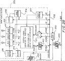
- the graphics system 300 as seen in Fig. 1, is structured about a compositing bus 305 which is generally 32 bits wide occupying 8 bits for each of red, green, blue and matte (transparencies) (RGBM) data.
- RGBM red, green, blue and matte
- the graphics system 300 includes a render processor 310 which is preferably a high performance 32 bit RISC processor such as the Intel i960 CA device with high speed DRAM memory interfaces and on-chip data and instruction caches.
- the render processor 310 also includes DMA channels for reading and writing ADCT+ compressed data to and from storage areas formed in DRAM.
- the main function of the render processor 310 is to convert render list data 398 into graphics engine commands 312. This process is known as BAND RENDER, and must be performed for each 8 line block of a page image and forms part of the render pipeline.
- the render processor 310 outputs RGBM data 314 to a graphics engine 320 which composites runs, blends, bit maps, and other graphics commands into a composite line store 330.
- the graphics engine 320 is critical to the high performance of the DTP system 100 as it performs pixel and line level operations in hardware. Generally, the graphics engine 320 performs operations at a rate of 13.5 million pixels per second, even where complex transparency and colour blend operations are to be performed for every pixel.
- the graphics engine 320 is capable of performing many operations at a rate 100 times faster than is presently available in software implementations.
- a full description of a specific example of the graphics engine 320 can be found in European Patent Application No. 91306080.2 claiming priority from Australian Patent Application Nos. PK1023 of 5 July 1990 and PK3419 of 19 November 1990 by the same applicant, the disclosure of which is incorporated by cross- reference.
- ADCT+ processor 340 which converts ADCT+ compressed images into pixel data and vice versa in the manner described in Australian Patent Application No. PK1784 entitled “Compressed Image Stores for High Resolution Computer Graphics” of 16 August 1990, from which priority is claimed, and European Application 9130 alone (agents ref. 2181230) filed on 15 August 1991 which is hereby incorporated by cross-reference.
- the ADCT+ processor 340 performs adaptive discrete cosine transforms of pixel data to provide compressed images in a manner described in the CCITT/ISO JPEG standard.
- the ADCT+ processor includes variations to the JPEG standard which permit improvements in the quality of reconstructed text and allows for the insertion of marker codes at the end of each 8 line block of compressed data.
- Using the ADCT+ processor 340 a full A3 400 dot per inch page image which would normally occupy 98 MBytes of DRAM, can be stored in approximately 4 MBytes of memory in the destination/source location 390 which generally occupies about 12 MBytes of the DRAM 420.
- the graphics system 300 includes a number of designated memory locations which are formed in DRAM. Those memory locations provide storage for Huffman tables 380, compressed image files 385, compressed image data 390 having both destination 391 and source 392 partitions, a buffer 395, the render list 397 and for font data 399. With reference to Fig. 2, each of these designated memory locations is formed within 32 megabytes of DRAM 420.
- the render list 397 is a low level object based description of an image to be shown on a workscreen 140 of the system 300.
- the workscreen 140 can be either a video display or a liquid crystal display.
- the render list 397 contains data indicative of individual spline definitions, individual character positions, ADCT+ compressed pixel images, and a spacial sub-division system for speed optimisation.
- the render list 397 is optimised for speed and is generally large in comparison with the display list 220. Approximately 4 MBytes of memory is allocated for the render list 397. In very complex object based images, more than this amount may be required. In such cases the image must be rendered in several passes.
- the font data cache 399 is used to store font data in both outline format and pixel format.
- the file store 385 contains an image file in ADCT+ compressed form which is typically an image file to be expanded and composited with the existing source image.
- the file ADCT+ image may contain more than one compressed image file. It is also forms part of the render pipeline.
- the source page image store 392 is a section of the DRAM 420. It forms part of the compositing pipeline. For each compositing pass, data in the source page image store 392 is expanded, compressed and written into the destination page image store 391 occupying adjacent memory locations in the DRAM 420. As the image source is no longer required when a new image is created, the source page image store 392 is overwritten by the destination page image.
- the destination page image store 391 stores the ADCT+ compressed page image after compositing.
- the destination page image of one compositing pass will typically become the source page image for the next compositing pass.
- the destination page image store 391 is also part of the compositing pipeline.
- the image buffer 395 is a section of the DRAM 420 used to temporarily buffer an 8 line block of the page image so that it can be processed by the render processor 310.
- the types of processing typically performed include formatting into graphics engine commands, and software anti-aliased zoom operations.
- the Huffman tables 380 are a section of the DRAM 420 used to store the set-up data for a JPEG compression/decompression device 415, seen in Fig. 2, which forms part of the ADCT+ processor 340.
- a JPEG compression/decompression device 415 is the C-Cube CL550B image compression processor.
- various tables and registers need to be changed. The largest of these is the Huffman table, but quantization tables and general registers must also be changed.
- the mode of the compression processor 415 is changed as many as 1,620 times during the composition of a single A3 page.
- the Huffman tables 380 are provided as a separate block of hardware to assist in the rapid change of the processor mode.
- This hardware consists of a DMA channel and a logic block 490 seen in Fig. 2 which converts the DMA data stream into direct control signals for the JPEG chip 415.
- a display frame store 370 connects to the composite bus 305 for the display of graphics images on the workscreen 140.
- the display frame store 370 is a frame store preferably comprising 1,280 pixels by 1,024 lines with 32 bits per pixel. There are 8 bits for each of red, green, blue and matte planes. The matte plane is not displayed but is used for compositing operations using the graphics engine 320.
- the display frame store 370 also includes a separate hardware cursor 375, seen in Fig. 2. The display frame store accordingly outputs RGB data to the workscreen 140.
- a pan/zoom controller 350 connects to the compositing bus 305 as well as to the display frame store 370 and is used to display a portion of-the full page in a window of the workscreen 140.
- the pan/zoom control unit 350 is capable of integer zoom ratios, such as 1:1, 2:1, 3:1, 4:1, etc. Zoom ratios required to view an entire A3 page on the workscreen is 6:1. Low zoom ratios are useful for close-up views of a portion of a page.
- the pan/zoom controller 350 is also capable of enlargement of the image for fine detailed work. Enlargements of up to 1:16 are available, resulting in a single page image pixel being written to a 16 x 16 pixel block of the workscreen 140.
- the DTP system 100 Apart from displaying images on the workscreen 140, the DTP system 100, using a colour laser copier 150, allows for image data to be scanned into the system 100 using a scanner 152 of the copier 150 and printed using a printer 154.
- the colour laser copier 150 can for example be the Canon Colour Laser Copier CLC500 or CLC300.
- the scanner 152 is capable of scanning an A3 page at 400 dots per inch resolution.
- the scanner output is in the form of 8 bits for each of red, green, and blue which are buffered simultaneously onto the compositing bus 305.
- the printer 154 is driven from the compositing bus 305 via a RGB to MCYK converter 360.
- the converter 360 converts red, green and blue data to magenta, cyan, yellow and black (MCYK) data which is used for the printing process of the printer 154.
- the compositing line store 330 is a high speed static memory array which provides 16 lines of page image storage.
- the compositing line store 330 has four 8 bit planes for red, green, blue and matte.
- the compositing line store 330 is used in several ways. Firstly, the line store 330 is used as a compositing memory for the page image. In this case, the graphics engine 320 composites 8 lines of object or image data at a time, and the system 300 advances to the next 8 lines of the page image.
- the line store 330 is used as a reordering line buffer for the ADCT+ processor 340.
- the compositing line store 330 is used to re-order 8 lines of image data from the 8 x 8 pixel block into 8 lines. All 16 lines of the compositing line store 330 are required in this instance, as the ADCT+ processor 340 must be able to write pixel blocks at the same time as pixel lines are being sent to the printer 154. A similar situation exists for the scanner 152, except in reverse.
- the DTP system 100 includes numerous data types that are transferred throughout. Already discussed, are the RGBM type transferred on the compositing bus 305 and RGB data transferred to the converter 360, from the scanner 152, and to workscreen 140.
- a synchronous 24 bit RGB pixel data is transferred to the display frame store 370 via data links 242 and the system bus 130.
- Such synchronous data is normally used only by the user interface 110 under the control of workscreen manager 240 (such as X-Windows), and is normally written to or read from the workscreen memory formed as VRAM 371 seen in Fig. 2.
- Compressed image data is formed by the ADCT+ PROCESSOR 340, and via the files memory 385 and image memory 390, can be buffered onto the system bus 130.
- the system bus 130, together with the network bus 105 carry mixed data types and can distribute those data types to peripheral devices connected to the network 105.
- the system 300 includes four main busses, one of which is the system bus 130 already described and another of which is the compositing bus 305, also described.
- a render bus 311 interconnects circuit components associated with image generation and editing. Connected to the render bus 311 is the render processor 310, a boot EPROM 430 which contains low level controlling software, the graphics engine 320 and the ADCT+ processor 340 which includes the JPEG device 415 and the ADCT extension 410.
- the system DRAM 420 connects via two bus drivers 450 and 451 to the render bus 311 and the system bus 130, respectively.
- a logic block 490 is provided for direct memory access (DMA) of the Huffman tables 380 stored in the DRAM 420 to the JPEG chip 415.
- a bus driver 452 is provided for direct memory access between the compositing memory 330 and the DRAM 420 via the data packer unit 410. At a bus driver 452 also allows direct memory access of the JPEG extension data stored in the DRAM 420 to the JPEG chip 415, via the ADCT extension unit 410.
- the display frame store 370 connects to the compositing bus 305 via a bus driver 454.
- the bus driver 454 supplies a VRAM 371 which is central to the display frame store 370.
- the VRAM 371 outputs to RAMDAC′s 372 for each of red, green and blue which provide video output to the workscreen 140.
- the display frame store 370 also includes an oscillator 373 which drives a clock generator 374 for the control of the RAMDAC 372.
- a separate cursor unit 375 is provided for control of the workscreen 140.
- a video bus 378 is provided which permits interconnection with the compositing bus 305 and the system bus 130. In this manner, workscreen data from a workscreen manager 240 can be buffered directly onto the video bus via a bus driver 453.
- the DTP system 100 supports all of the capabilities of a page imaging system on the workscreen 140. To enable interactive graphics in a window environment, the workscreen 140 also has some other capabilities, including:
- the system 100 hardware supports continued operation while page compositing is in process. This operation can be in two ways:
- Interactive graphics and object graphics operations to the workscreen can continue while printing or scanning.
- the DTP system 100 cannot perform any combination of printing, scanning, or compositing simultaneously. This is because printing and scanning are synchronous operations which both require the compression processor for their full duration.
- rendering opaque images involves writing pixel image data into memory.
- rendering transparent images involves compositing newly rendered objects with existing pixel image data.
- ADCT+ compressed image store 390 requires that the image must be calculated in essentially the same order as the printer 154 requires the output data for printing.
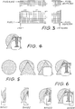
- Canon colour laser printing process printing occurs from the bottom left to the top right of an A3 page in landscape mode, as seen in Fig. 3.
- This method has the advantage of simplicity in that the image generation process need only consider each object in turn. This simplicity makes the method relatively easy to optimise for speed. Generally, a complete pixel mapped image store is required. For full colour A3 images at 400 dpi, this results in a memory requirement of approximately 96 MBytes per page.
- Band rendering has the disadvantage of complexity in that all of the objects must be stored, usually in a display list, and the appropriate section of each object must be created for each band.
- the painters algorithm can be used to overlay the visible objects in that band. This usually is substantially slower than when an entire page store is available, as each object must be created and clipped to each band.
- the ADCT+ image compression system used in the DTP system 100 works on blocks of 8 x 8 pixels.
- An A4 image with 6,480 lines x 4,632 pixels contains 810 x 579 pixel blocks.
- the rendering system in the DTP system 100 renders bands of 579 pixel blocks (8 vertical scan lines) in one pass. This rendering process must be repeated for 810 bands to render an entire A3 image.
- the combination of these techniques makes the DTP system 100 operate at very high speed.
- A3 size images can be created in as little as 6 seconds, and will typically take less than 20 seconds. This means that the DTP system 100 image generation speed is comparable to the Colour Copier print speed under most circumstances.
- image creation order must be from left to right of an A3 page in landscape format, or an A4 page in portrait format.
- Horizontal compositing runs to the 8 line buffer for the page image would be limited to eight pixels long, so only vertical runs are supported. There is no access to individual pixels of the page image without expanding and compressing the entire page.
- the screen image has no such limitations.
- the image can be built in any order, and runs can be either vertical or horizontal. Individual pixels can also be addressed in random order. This makes the generation of interactive user interfaces substantially easier.
- the image is processed in bands generally 8 lines wide. Because of this, the composite line store 330 is preferably a multiple of 8 lines. Most preferably it is formed having a 24 line capacity including source, composite and destination locations.
- the band processing of data allows for individual processing steps to be pipelined which improves image generation speed.
- This configuration provides for buffering of an expanded file image into the buffer 395 in DRAM, where it can be processed by the render processor 310. This step is performed where there is no matte associated with the file image. Where a matte is included, the step "Buffer file image and matte" is used.
- Eight lines of RGB pixel data from the expanded image file are copied from the composite line store 330 into the DRAM buffer 395. This copying is performed by block DMA transfers initiated by the render processor 310.
- This step will be performed once for every 8 line block of the image file. Buffering of the image data is required in most circumstances because the image data will typically be much larger than the command FIFO (seen in Fig. 2) of the Graphics Engine 320, and the composite line store 330 cannot be read at the same time as compositing.
- This configuration provides for the buffering of an expanded file image and file matte into the DRAM buffer 395, where it can be processed by the render processor.
- This data is in RGBM format, and can be transferred directly as RGBM pixels to the graphics engine 320.
- Eight lines of RGBM pixel data from the expanded image file are copied from the composite line store 330, into the DRAM buffer 395. This copying is performed by block DMA transfers of the render processor 310.
- eight lines of a file image must be expanded into the composite line store 330
- eight lines of a file matte must be expanded into the composite line store 330
- the DMA controller in the render processor 310 must be set up to transfer data from the compositing line store 330 to the DRAM buffer 395.
- This configuration provides for the compositing of RGB image data with the composite line buffer 330 using the combination of an image matte and object transparency or a file matte.
- RGB and matte pixel data is read from the compositing line buffer 330, composited with data generated by the graphics engine 320, and written back to the compositing line buffer 330 at the same address.
- the RGB data generated by the graphics engine 320 can be in the form of object based data expanded into Colour Runs or Colour Blends, or RGB pixel data derived from File images which are transferred the graphics engine 320.
- the compositing is controlled by the combination of matte data in the compositing line store 330 and transparency data generated by the graphics engine 330.
- This transparency data can be in the form of object based data expanded into Transparency Runs or Transparency Blends, Bitmap data, or Matte pixel data derived from File images which are transferred the graphics engine 320.
- graphic engine commands 312 must be established in the graphics engine 320.
- This configuration provides for the clearing of the compositing line buffer 330 prior to the generation of images.
- the compositing line buffer 330 has the capability of being cleared as the composited image is compressed. Therefore, it is only necessary to explicitly clear the compositing line buffer 330 for the first 8 line block of the image.
- a Display list is usually the first step in the creation of an image.
- a Display list is composed of data describing the image, and may contain graphic objects, text, and ADCT+ compressed images.
- the DTP 100 rendering system accepts display lists in the form defined by the command interface software layer (SCI).
- a display list 220 may be derived from several sources:
- This configuration provides for the compositing of RGB image data with the composite line buffer 330.
- This step is performed where there is no matte associated with the page image. Where a Page matte is included, the step "Compositing using page matte" is used.
- RGB pixel data is read from the compositing line store 330, composited with data generated by the graphics engine 320, and written back to the compositing line store 330 at the same address.
- the RGB data generated by the graphics engine 320 is in the form of RGB pixel data derived from File images which are transferred to the graphics engine 20.
- the compositing is controlled by Matte pixel data derived from a File matte which are transferred to the graphics engine 320.
- graphic engine commands 312 must be established in the graphics engine 320, and 8 lines of the page image must exist in the compositing line store 330.
- This configuration provides for the process of compressing a File image after scanning.
- an image When an image is initially scanned, it will typically be an entire A3 image. This is used to trim a scanned image for saving as a File image.
- the ADCT+ processor 340 must be set up into compression mode
- the DMA controller 425 must be set up to transfer data from the ADCT+ system 340 to the destination compressed page image 391 in DRAM 420
- the compositing line store 330,address generator must be set up with the appropriate start pixels and line length for the destination image size and position.
- This configuration provides for the process of compressing a file matte after compositing. This step also clears the matte plane of compositing buffer 330 to transparent to prepare for object graphics in the next 8 line block.
- Eight lines of the composited matte pixel data in the Compositing line buffer 330 are compressed by the ADCT+ system 340 in compression mode. This data is written to the destination compressed file matte 391 in DRAM 420.
- the data required by the ADCT+ system 340 is in 8 x 8 pixel blocks, but is stored in the compositing line buffer 330 in Raster format. Therefore, the address sequence used when reading from the line buffer re-orders the data.
- the ADCT+ processor 340 must be set up into compression mode, the DMA controller in the render processor 310 must be set up to transfer data from the ADCT+ system 340 to the destination compressed file matte 391 in DRAM 420.
- the compositing line store 330 address generator must be set up in the appropriate re-ordering mode.
- This configuration provides for the compositing of RGB image data with the Composite line buffer 330.
- RGB pixel data is read from the compositing line buffer 330, composited with data generated by the graphics engine 320, and written back to the compositing line buffer 330 at the same address.
- the RGB data generated by the graphics engine 320 is in the form of RGB pixel data derived from File images which are transferred to the graphics engine 320.
- the compositing is controlled by transparency data generated by the graphics engine 320, which is in the form of object based data expanded into Transparency Runs or Transparency Blends or Bitmap data.
- Graphicengine commands 312 must be established in the graphics engine 320 and 8 lines of the page image must exist in the compositing line store 330.
- This configuration provides for the compositing of RGB image data with the composite line buffer 330 using a matte associated with the page image.
- RGB and matte pixel data is read from the compositing line store 30, composited with data generated by the graphics engine 320, and written back to the compositing line store 330 at the same address.
- the RGB data generated by the graphics engine 320 is in the form of RGB pixel data derived from file images which are transferred to the graphics engine 320.
- graphic engine commands 312 must be established in the graphics engine 320, 8 lines of the page image must exist in the compositing line store 330 and 8 lines of the page matte must exist in the compositing line store 330.
- Matte pixel data is read from the compositing line store 330, composited with data generated by the graphics engine 320, and written back to the compositing line store 330 at the same address.
- the matte (transparency) generated by the graphics engine 320 is in the form of object based data expanded into Transparency Runs or Transparency Blends or Bitmap data. Either the page matte of the file matte may be composited using this method.
- Graphic engine commands 312 must be established in the graphics engine 321 and 8 lines of the page matte or file matte must exist in the compositing line store 330.
- This configuration provides for the compositing of object based graphics (and text) with the composite line buffer 330
- RGB pixel data is read from the compositing line buffer 330, composited with data generated by the graphics engine 320, and written back to the compositing line buffer 330 at the same address.
- the RGB data generated by the graphics engine 320 is in the form of object based data expanded into Colour runs or Colour blends.
- the compositing is controlled by transparency data generated by the graphics engine 320, which is in the form of object based data expanded into Transparency Runs or Transparency Blends or Bitmap data.
- Graphic engine commands 312 must be established in the graphics engine 320 and 8 lines of the page image must exist in the compositing line buffer 330, except where the compositing memory is completely filled with opaque runs (for example, when using the White Run command to generate a blank background).
- This configuration provides for the process of compressing a Page image after compositing. This step also clears the compositing buffer 30 to white to prepare for object graphics in the next 8 line block.
- Eight lines of the composited RGB pixel data in the Compositing line buffer 330 are compressed by the ADCT+ system 340 in compression mode. This data is written to the destination compressed page image 391 n DRAM 420.
- the data required by the ADCT+ system 340 is in 8 x 8 pixel blocks, but it is stored in the compositing line buffer 330 in Raster format. Therefore, the address sequence used when reading from the line buffer reorders the data.
- the ADCT+ processor 340 For preconditions the ADCT+ processor 340 must be set up into compression mode, the DMA controller in the render processor 310 must be et up to transfer data from the ADCT+ system 340 to the destination compressed page image 391 in DRAM 420, and the compositing line buffer address generator 410 must be set up in the appropriate re-ordering mode.
- This configuration provides for the process of compressing a page Matte after compositing. This step also clears the matte plane of compositing buffer 330 to transparent to prepare for object graphics in the next 8 line block.
- Eight lines of the composited matte pixel data in the Compositing line buffer 330 are compressed by the ADCT+ system 340 in compression mode. This data is written to the destination compressed page matte 391 n DRAM 420.
- the data required by the ADCT+ system is in 8 x 8 pixel blocks, but is stored in the compositing line buffer 330 in Raster format. Therefore, the address sequence used when reading from the line buffer reorders the data.
- the ADCT+ processor 340 must be set up into compression mode, the DMA controller in the render processor 310 must be set up to transfer data from the ADCT+ system 340 to the destination compressed page matte 391 in DRAM 420 and the compositing line buffer 330 address generator 410 must be set up in the appropriate re-ordering mode.
- This data path is used to convert a display list 220 in the form defined by the command interface (SCI) layer into a render list 397.
- SCI command interface
- the conversion from a display list 220 to a render list 397 is performed by the Host Render program running on the G.P. processor 230.
- the display list 220 is read from memory on the computer system 200, converted, and stored as a render list in the shared memory (DRAM 420).
- ADCT+ image files which form part of the display list 220 are transferred to the shared memory (420) without alteration. While these are part of the render list 397, they are shown separately as their data path diverges from that of object graphics after this stage.
- a display list 220 in command interface layer format is required for conversion.
- This configuration provides for the compositing of object based graphics (and text) with the workscreen 140.
- This configuration is used to provide high speed interactive WYSIWYG graphics.
- RGB pixel data is read directly from the display frame store 370, composited with data generated by the graphics engine 320, and written back to the display frame store 370 at the same address.
- memory access to the workscreen 140 is substantially slower than to the compositing line buffer 330, so the compositing pixel rate will be much lower.
- the workscreen 140 contains only 4.37% as many pixels as the page image, so the image creation rate should be acceptable.
- Graphics engine commands 312 must be established in the graphics engine 320.
- This configuration provides for compositing of object based graphics (and text) with the workscreen 140, using the workscreen matte plane. This configuration is used to provide high speed interactive WYSIWYG graphics.
- RBG and matte pixel data is read directly from the display frame store 370, composited with data generated by the graphics engine 320, and written back to the display frame store 370 at the same address.
- the workscreen matte plane is not altered by this process.
- the DTP system 100 has the capability of simulating the cumulative interaction between paint and a textured background.
- the matte plane is also altered during compositing. Note that memory access to the workscreen 140 is substantially slower than to the Compositing line buffer 330, so the compositing pixel rate will be much lower.
- the workscreen contains only 4.37% as many pixels as the page image, so the image creation rate should be acceptable.
- Graphics engine commands 312 must be established in the graphics engine 330.
- This configuration provides for the drawing of graphics to the workscreen 140 by writing individual pixels via direct access to the workscreen VRAM 371.
- This method is relative slow, but allows pixels to be written in any order, and access to the workscreen memory 371 by this method is available at all times.
- RGB pixel data is written directly to the workscreen memory 371, by the G.P. processor 320.
- This configuration provides for the process of expanding a compressed image file ready for compositing with the source image.
- Eight lines of the ADCT+ compressed image file 385 are expanded into RGB pixel data by the ADCT+ system 340 in expansion mode. This data s written directly to the composite line buffer 330.
- the data from the ADCT+ system 340 is in 8 x 8 pixel blocks, but is stored in the composite line buffer 330 in Raster format. Therefore, the address sequence used when writing to the line buffer re-orders the data. This step will be performed once for every 8 line block of the image file.
- the preconditions are that the ADCT+ processor 340 must be set up into expansion mode, the DMA controller in the render processor 310 must be set up to transfer data from the file image 385 in DRAM 420 to the ADCT+ expander 340, and the composite line buffer 330 address generator 410 must be set up in the appropriate reordering mode.
- This configuration provides for the process of expanding a File matte before compositing.
- the File matte can be used to control compositing of Files with the page image.
- Eight lines of the ADCT+ compressed file matte are expanded from the source 392 into Matte pixel data by the ADCT+ system 340 in expansion mode. This data is written directly to the matte plane of the composite line buffer 330. The RGB planes of the composite line buffer are not affected.
- the data from the ADCT+ system 340 is in 8 x 8 pixel blocks, but is stored in the composite line buffer 330 in Raster format. Therefore, the address sequence used when writing to the line buffer re-orders the data.
- the ADCT+ processor 340 must be set up into expansion mode, the DMA controller in the render processor 310 must be set up to transfer data from the file matte 392 in DRAM 420 to the ADCT+ expander340, and the compositing line buffer 340 address generator 410 must be set up in the appropriate reordering mode.
- This configuration provides for the process of expanding a Page image ready for compositing. This is generally the first step in the process of compositing new information with an existing page image.
- Eight lines of the ADCT+ compressed Page image are expanded from the source 392 into RGB pixel data by the ADCT+ system 340 in expansion mode. This data is written directly to the composite line buffer 330.
- the data from the ADCT+ system 340 is in 8 x 8 pixel blocks, but is stored in the compositing memory in Raster format. Therefore, the address sequence used when writing to the line buffer re-orders the data.
- the preconditions are that the ADCT+ processor 340 must be set up into expansion mode, and the DMA controller in the render processor 310 must be set up to transfer data from the source image 392 in DRAM 420 to the ADCT+ expander, and the compositing line buffer 330 address generator 10 must be set up in the appropriate re-ordering mode.
- This configuration provides for the process of expanding a Page matte before compositing.
- the page matte can be used to control compositing of files and object graphics with the page image.
- Eight lines of the ADCT+ compressed page matte are expanded from the source 293 into matte pixel data by the ADCT+ system 340 in expansion mode. This data is written directly to the Matte plane of the'composite line buffer 330. The RGB planes of the composite line buffer 330 are not affected. The data from the ADCT+ system 340 is in 8 x 8 pixel blocks, but is stored in the compositing line buffer 330 in Raster format.
- the address sequence used when writing to the line buffer re-orders the data.
- Preconditions are that the ADCT+ processor 340 must be set up into expansion mode, the DMA controller in the render processor 310 must be set up to transfer data from the page matte 392 in DRAM 420 to the ADCT+ expander, and the compositing line buffer 330 address generator 410 must be set up in the appropriate reordering mode.
- the ADCT+ format file is passed from the display list 220 through a "filter” program in the applications layer 245 which converts the file to JPEG format which then written to the Hard Disk (HDD) 124 or Magneto-Optical Disk (MOD) 122 under the control of the operating system 235.
- HDD Hard Disk
- MOD Magneto-Optical Disk
- This configuration provides for the formatting of an expanded and buffered file image 395 from RGB pixels into graphics engine commands 312. This step is performed where there is no matte associated with the file image. Where a matte is included, the step "Format file image and matte" is used.
- a graphics engine command 312 header is written to the graphics engine 320, specifying the number of pixels to be composited, the start pixel address, and the compositing mode.
- the graphics engine 312 command includes RGB pixel data
- the run of RGB pixel data from the buffered image file is copied by the DRAM buffer 395 into the graphics engine 320. This copying is performed by render processor 310 performing block DMA transfers. This run may be longer than a graphics engine 320 FIFO 321 length (seen in Fig. 2), in which case a FIFO 321 full signal temporarily stalls the DMA transfer. This step is performed once for every compositing run. There are typically eight compositing runs for each 8 line block of an image file.
- the RGB image data must be in the DRAM buffer 95, and the DMA controller in the render processor 310 must be set up to transfer data from the DRAM buffer 395 to the Graphics engine FIFO 321.
- This configuration provides for the formatting of an expanded and buffered file image and file matte from RGBM pixels into graphics engine commands 312.
- a graphics engine command 312 header is written to the graphics engine 320, specifying the number of pixels to be composited, the start pixel address, and the compositing mode.
- the relevant graphics engine commands 312 include RGBM pixel data from the buffered file image pixel data. This data is copied from the DRAM buffer 395 into the graphics engine 320 by the render processor 310 performing block DMA transfers.
- the data run may be longer than the graphics engine FIFO 321 length, in which case the FIFO full signal temporarily stalls the DMA transfer. This step is performed once for every compositing run. There are typically eight compositing runs for each 8 line block of an image file.
- the preconditions are that the RGBM image data must be in the DRAM buffer 395, and the DMA controller 425 must be set up to transfer data from the DRAM buffer 395 to the graphics engine FIFO 321.
- the JPEG format file is read from the Hard Disk (HDD) 124 or Magneto-Optical Disk (MOD) 122 under the control of the operating system 235 and passed through a "filter" program in the applications layer 245 which converts the file to ADCT+ format for storage in the display lists 220.
- HDD Hard Disk
- MOD Magneto-Optical Disk
- This configuration provides for the fast expansion and writing of a file image directly to the compositing line store 330.
- Eight lines of the ADCT+ compressed image file 385 are expanded into RGB pixel data by the ADCT+ system 340 in expansion mode. This data is written directly to the compositing line buffer 330. This will overwrite the existing contents of the compositing line buffer 330 in the rectangular region specified.
- the preconditions are that the ADCT+ processor 340 must be set up into expansion mode, the DMA controller in the render processor 310 must be set up to transfer data from the file image 385 in DRAM 420 to the ADCT+ expander 340, and the compositing line buffer 330 address generator must be set up in the appropriate reordering mode.
- This data path is used to set up the JPEG Chip 415 into compress mode. This must be done whenever a compression is to be performed when the chip is currently in expand mode.
- the compress Huffman tables 380 and the other setup data for the JPEG chip 415 are transferred from DRAM 420 to the JPEG chip 415 by a DMA controller on the render processor 310.
- This data is in a special format which includes control data, and is written to a hardware location containing circuitry which interprets this data as control signals for the JPEG chip 415. This is so that the entire set-up of the various registers and arrays in the chip 415 can be achieved very rapidly.
- the JPEG chip 415 must be changed from expand mode to compress mode (and back again) 810 times to composite a full A3 sized image.
- Set-up data for the JPEG chip 415 is loaded into DRAM at boot time.
- This data path is used to set up the JPEG chip 415 into expand mode. This must be done whenever an expansion is to be performed when the chip 415 is currently in compress mode.
- the expand Huffman tables 380 and other setup data for the JPEG chip 415 are transferred from DRAM 420 to the chip 415 a DMA controller on the render processor 410.
- This data is in a special format which includes control data, and is written to a hardware location containing circuitry which interprets this data as control signals for the JPEG chip 415. This is so that the entire set-up of the various registers and arrays in the chip 415 can be achieved very rapidly.
- the chip 415 must be changed from compress mode to expand mode (and back again) 810 times to composite a full A3 sized image.
- Set-up data for the JPEG chip 415 is loaded into DRAM at boot time.
- This configuration shows the process of printing an image.
- the compressed page image is expanded into RGB pixel data in real time, converted to MCYK data, and printed one colour component at a time.
- the ADCT+ compressed page image 392 is expanded into RGB pixel data in real time by the ADCT+ system 340 in expansion mode.
- This data is written directly to the compositing line store 330, which is used as a reordering line store to convert the 8 x 8 pixel cells generated by the ADCT processor into raster data.
- the data is then converted in the converter 360 from RGB into Magenta, Cyan, Yellow, and Black, and printed.
- the colour laser printer 154 requires synchronous data which cannot be stopped in mid process. Therefore, the print operation must be treated as a single indivisible operation, and must operate in real time.
- the expansion, conversion and printing process is performed four times for each copy to be printed: once for each of the Magenta, Cyan, Yellow, and Black colour printing passes. Data output timing is controlled by line and page sync signals from the printer 154.
- the preconditions are that the ADCT+ processor 340 must be set up into expansion mode, the DMA controller in the render processor 310 must be set up to transfer data from the DRAM 420 to the ADCT+ expander 340 and an RS232C print command is given to the printer 154.
- This configuration provides a zoom function performed by software in the render processor 310. This duplicates the function of the hardware pan-zoom engine 350 when displaying an image to the workscreen 140. The zoom is not anti-aliased.
- the graphics engine 320 reads 8 lines of the RGB and matte pixel data from the buffer image 395 and creates a zoomed version of this for the workscreen by discarding a portion of the pixels. This zoomed version is written back to the image buffer 395. This version can then be transferred to the graphics engine 320 using DMA transfers.
- the only precondition is that the RGBM image data must be in the buffer 395 of the DRAM 420.
- Display lists 220 may include ADCT+ image files.
- the display list 20 must directly contain the ADCT+ filename, size, x/y size, matte configuration, and other characteristics, but need not contain the actual ADCT+ data, which can be as large as 4 MBytes.
- the host render process 250 does not directly alter or use the ADCT+ data, this can be transferred directly to the memory (DRAM 420) from disk 120 as and when required. This avoids the double transfers necessary if the data is saved in a display list 220 on the computer system 200, and can therefore improve performance and reduce memory requirements. This is particularly significant for multiple page documents with many file images, where object data and text tends to be very compact.
- On demand direct loading of ADCT+ data means that very long colour documents can be edited and printed without running out of memory. .
- the ADCT+ file is read from the Hard Disk (HDD) 124 or Magneto-Optical Disk (MOD) 120 under the control of the operating system 235 and written directly to the DRAM 420 by SCSI DMA transfers from the port 210.
- HDD Hard Disk
- MOD Magneto-Optical Disk
- the only precondition is that sufficient space must be available in the DRAM 420. This requires communications between the memory management running on the render processor 310 and the operating system 235.
- This configuration provides for the re-sizing of an ADCT+ image, performed by software on the render processor 310. This resizing is performed when the image required on the page is a different size than the image stored in the file.
- the render processor 310 reads 8 lines of the RGB and matte pixel data from the buffer image 395 and creates a resized version of this for the workscreen 140 using bi-linear sample rate conversion. This resized version is written back to the image buffer 395.
- the resized image can .hen be transferred to the graphics engine 320 using DMA transfers. The only precondition is that the RGBM image data must be in the RAM buffer.
- This data path is used to convert the object descriptions in a render list 397 into graphics engine "Transparency" commands 312.
- the conversion from a render list 397 to Graphics engine commands is performed by a program running on the render processor 310 called BAND RENDER which performs band rendering in the manner already described.
- the render list 397 is read from shared memory 420 converted, and stored as commands in the Graphics engine command FIFO 321.
- One "band” of 8 lines wide is rendered at a time. 810 bands must be rendered for a full A3 sized image, and 405 bands are required for an A4 image.
- the only precondition is that a render list containing the object matte must be established.
- This data path is used to convert the object descriptions in a render list 397 into graphics engine commands 312.
- the conversion from a render list 397 to graphics engine commands 312 is performed by a program running on the render processor 310 called BAND RENDER.
- the render list 397 is read from shared memory 420, converted, and stored as commands in the Graphics engine command FIFO 321.
- One "band” of 8 lines wide is rendered at a time 810 bands must be rendered for a full A3 sized image, and 405 bands are required for an A4 image.
- the preconditions for this process are that a render list 397 in appropriate format is required for rendering, all font descriptions required by text in the render list 397 must be available, either in the font cache 399, or by requesting the computer system 200, and the graphics engine command FIFO 321 must not be full. Block synchronisation with the FIFO 321 is required.
- Display lists 320 are read from disk 120 as a named file by an application, and as spooled information for printing.
- a display list is composed of data describing the image, and may contain graphic objects, text, and ADCT+ compressed images.
- the display list 220 is read from the Hard Disk (HDD) 124 or Magneto-Optical Disk (MOD) 122 under the control of the operating system 235 and written to DRAM (not illustrated) in the computer system 200.
- HDD Hard Disk
- MOD Magneto-Optical Disk
- Normally Display lists are received from the Network 105 (Ethernet) as a remote printing job from another workstation on the network 105. This differs from reading a Display List from disk in that the task will normally be initiated remotely, and can coincide with display list manipulation occurring locally under the control of the application. This function is facilitated by allowing multiple Display lists to exist at the same time.
- the Display list is received from Ethernet 105 under the control of the operating system 235 and written to DRAM (not illustrated) on the computer system 200.
- This configuration shows formatting of an expanded and buffered File Image from RGB pixels into graphics engine commands 312, at the same time as rendering an object based matte.
- the conversion from a render list 397 to graphics engine commands 312 is performed by a program running on the render processor 310 called BAND RENDER.
- a graphics engine command 312 of a type containing a Transparency Run or Transparency Blend followed by pixel data is written to the graphics engine 320. This is followed by the RGB pixel data from the buffered file image 395. This data is copied from the DRAM buffer 320 into the graphics engine 320 by the render processor 310 performing block DMA transfers.
- the preconditions are that a Render list 397 containing the object matte must be established, the RGB image data must be in the DRAM buffer 395 and the DMA controller in the render processor 310 must be set up to transfer data from the DRAM buffer 420 to the graphics engine FIFO 312.
- This configuration shows scanning an image and compressing the file in ADCT+ format.
- the scanner 152 uses the scanner 152, only a complete A3 page can be scanned using this method.
- a Trim Scan operation can be used to create smaller files (see the applications section following).
- the scanned image is not shown on the workscreen 140. This can be achieved using the Scan to workscreen operation.
- the scanner 152 data is written directly to the compositing line store 330.
- the compositing memory is used as a re-ordering line store to convert the raster data from the scanner 152 to the 8 x 8 pixel cells required by the ADCT+ processor 340. While the scanner data is written to one half of the reordering line store, it is read from the other half by the ADCT+ processor 340 and compressed to create the destination image 391.
- the data from the scanner 152 is synchronous, so the scan operation must be treated as a single indivisible operation, and must operate in real time.
- the preconditions are that the ADCT+ processor 340 must be set up into compression mode, the DMA controller in the render processor 310 must be set up to transfer data from the ADCT+ compressor 340 to the DRAM 420, and an RS232C scan command is given to the scanner 152.
- This configuration provides for the scanning of an image and displaying a reduced version on the workscreen 140. This is used to accurately position the image on the scanner 152 and ensure that the zoom ratios, image angle, and other factors are correct before performing the final scan of the image.
- the Scanner data is written to the compositing line store 330.
- the compositing line store 330 is used as an image buffer to allow a synchronous operation of the scanning and transfer to the workscreen 140.
- the scanner data is written to one half of the image buffer, it is read from the other half by the graphics engine 320, which provides the pan-zoom 350 controller with start addresses and zoom ratios.
- a selection of the pixels from the scanned image are written to the workscreen 140 under the control of the pan-zoom controller 350.
- the scan operation must be treated as a single operation, and must operate in real time.
- graphics engine commands 312 are established to set up the pan-zoom controller 350 with the start address of every run. These commands should take into account the zoom ratio of the image, the size and position of the image window, and the presence of any windows which may overlay the image window, and an RS232C scan command is given to the scanner 152.
- ADCT+ images are usually saved to disk as a "File Image” after scanning and trimming.
- ADCT+ images may be stored in the DRAM 420 and directly transferred to disk 120. This avoids the double transfers necessary if the data is saved in a Display list on the computer system 200, and can therefore improve performance and reduce memory requirements.
- the ADCT+ file is read from the DRAM 420 under the control of the operating system 235 and written directly to the Hard Disk (HDD) 124 or Magneto-Optical Disk (MOD) 122 by SCSI DMA transfers instituted by the port 210.
- HDD Hard Disk
- MOD Magneto-Optical Disk
- a Display list is composed of data describing the image, and may contain graphic objects, text, and ADCT+ compressed images.
- the display list 220 resides in DRAM (not illustrated) on the computer system 200. It is written to the hard Disk (HDD) 124 or Magneto-Optical Disk (MOD) 122 under the control of the operating system 235
- the graphics engine 320 can be used.
- the graphics engine 320 can draw either horizontal or vertical (but not diagonal) runs. Therefore filled shapes and aligned lines can be drawn very rapidly, but diagonal lines are slow.
- X-Windows can draw to the screen, including:
- X-Windows running on the G.P. processor 230, directly creates graphics engine commands 310 for the Workscreen 140, and passes them to the render processor 310, which places them in the graphics engine command FIFO 321.
- This configuration provides the process of expanding a Page image to display a portion of it on the Workscreen 140.
- the ADCT+ compressed page image 392 is expanded into RGB pixel data by the ADCT+ system 340 in expansion mode. This data is written directly to the compositing line store 330.
- the compositing line store 330 is used as a re-ordering line store to convert the 8 x 8 pixel cells generated by the ADCT+ processor 340 into raster data required by the Pan-Zoom engine 350.
- the graphics engine 320 reads lines of pixels from the compositing line store 330 and writes them to the pan-zoom engine 350.
- the preconditions are that the ADCT+ processor 340 must be set up into expansion mode, the DMA controller in the render processor 310 must be set up to transfer data from the Source image 392 in DRAM 420 to the ADCT+ expander 340, the compositing line store 330 address generator 410 must be set up in the appropriate reordering mode, and graphics engine commands 312 are established to set up the pan-zoom controller 350 with the start address of every run. These commands should take into account the zoom ratio of the image, the size and position of the image window, and the presence of any windows which may overlay the image window.
- the tables are arranged to show those processing steps that are performed simultaneously and sequentially.
- Example 1 Composite Layers of Objects with Image
- Table 1 shows the steps necessary when compositing graphic objects or text over an existing ADCT+ image. This process is normally be done as part of an interactive image composition sequence. The number of layers of graphic objects that can be composited in one pass is limited only be available render list memory. Typically, many thousands of objects are generally composited in one pass. In subsequent compositing diagram, all contiguous layers of object graphics are shown as a single layer. Table 1 Notes
- Table 2 shows the steps necessary when compositing an ADCT+ compressed file image with the existing ADCT+ page image.
- This configuration uses an ADCT+ compressed Matte associated with the file to control the compositing of the file image with the page image. This process would normally be done as part of an interactive image composition sequence.
- a file matte will usually be used to "cut out" the region of interest in a photograph.
- Table 3 shows the steps necessary when compositing an ADCT+ compressed file image with the existing ADCT+ page image.
- This configuration uses an ADCT+ compressed Matte associated with the page image to control the compositing of the file image with the page image. This process is normally be done as part of an interactive image composition sequence.
- a page matte is usually used to "protect" some region of the page image from being composited over.
- Table 4 shows the steps necessary when compositing an ADCT+ compressed file image with the existing ADCT+ page image.
- This configuration uses the simultaneously combination of two mattes to control the compositing of the file image with the page image.
- These mattes are a matte associated with the page image (the Page Matte) and the matte associated with the file image (the File Matte). This can be used for various special effects, such as to "insert” a file image behind some portions of the page image and in front of other portions, to control the density of an image based on a page "texture” as well as to allow the placement of images with transparent regions into a "window” (which may be irregular and of variable density) on the page.
- Table 4 Notes
- Table 5 shows the steps necessary when compositing and printing object based images or text, on a blank page.
- the number of layers of graphic objects that can be composited in one pass is limited only be available render list memory. Typically, many thousands of objects could be composited in one pass.
- all contiguous layers of object graphics are shown as a single layer.
- the background is white. If other colour backgrounds are required, they must be created by overlaying the background with full page graphic objects.
- Table 6 shows the printing of an existing page image, which will typically be in the Source ADCT+ image memory 392.
- Table 7 shows the steps necessary when compositing and printing an ADCT+ Image file with associated ADCT+ Matte, as well as object based images or text, on a blank page.
- the background is white. If other colour backgrounds are required, they must be created by overlaying the background with full page graphic objects. Table 7 Notes
- Example 8 Print 2 Images with Object Mattes, and Text
- Table 8 shows the steps necessary when compositing and printing two ADCT+ Image files, each with object based Mattes, on a blank page.
- the top layer of the image contains Object based text or graphics. This compositing sequence is only required in regions where the two ADCT+ images share vertical compositing blocks. Where there is no vertical overlap, the compositing may proceed as if there were only one image.
- the background is white. If other colour backgrounds are required, they must be created by overlaying the background with full page graphic objects. Table 8 Notes
- Table 9 shows the steps necessary when compositing and printing two ADCT+ Image files, each with associated ADCT+ Mattes, as well as object based text, on a blank page. This compositing sequence is only required in regions where the two ADCT+ images share vertical compositing blocks. Where there is no vertical overlap, the compositing may proceed as if there were only ,one image. The background is white. If other colour backgrounds are required, they must be created by overlaying the background with full page graphic objects. Table 9 Notes
- Table 10 shows fast creation of a page with three images and text. This fast compositing method can only be used where there is no matte associated with the image, where there is no page matte, and where the image is aligned to the 8 x 8 ADCT+ pixel grid. Alignment to the grid created a maximum positioning error of +4 pixels, or +O.25 mm. In many circumstances, this position constraint is irrelevant. Alignment to the grid also preserves image quality, as the image will not alter when expanded and re-compressed if the image is grid-aligned. When there is no matte associated with the image, the image will be fully opaque, and rectangular. Table 10 Notes
- Table 11 shows the steps necessary when displaying a portion of the page image on the workscreen 140 without modifying it. This is used when panning or zooming to display a different portion of the page image than that currently displayed. Table 11 Notes
- Table 12 shows the steps necessary when directly compositing WYSIWYG object graphics to the workscreen 140. This process wound normally be done as part of an interactive image composition sequence, building a display list which can later be rendered to the page image.
- the number of layers of graphic objects that can be composited in one pass is limited only by available render list memory 397. Compositing to the workscreen 140 has fewer constraints than compositing to the page image, as both horizontal and vertical runs are available, and compositing can proceed in any scan-line order, as long as the viewing order of the objects is maintained. Table 12 Notes
- Table 13 shows the steps necessary when directly compositing ADCT+ files to the workscreen 140 using a file matte. This process would normally be done as part of an interactive image composition sequence, building a display list which can later be rendered to the page image. Note that this general method is necessary when compositing to the workscreen 140 using a matte, but the faster method of directly writing the image to the workscreen 140 using the pan-zoom engine 350 can be used where the image is rectangular and there is no matte involved. Table 13 Notes
- Table 14 shows the steps necessary when directly writing an ADCT+ file to the workscreen 140 where the image is rectangular and there is no ADCT+ matte or object matte involved. This is the fastest method, as the Pan-zoom engine 350 is used. This process would normally be done as part of an interactive image composition sequence, building a display list which can later be rendered to the page image. Table 14 Notes
- Table 15 shows the steps necessary when directly compositing ADCT+ files to the workscreen using an object based matte. This process would normally be done as part of an interactive image composition sequence, building a display list which can later be rendered to the page image. Note that this general method is necessary when compositing to the workscreen 140 using a matte, but the faster method of directly writing the image to the workscreen 140 using the pan-zoom engine 350 can be used where the image is rectangular and there is no matter involved. This method is suitable when the object matte is simple. For object mattes containing multiple layers of overlapping transparency see the sequence on "compositing with complex object mattes". Table 15 Notes
- Table 16 shows the configuration used when the user wishes to see the result of a scan without saving a file to disk 120. This will usually be in order to position the scanned image correctly. This process does not produce a "destination" ADCT+ image.
- Example 17 Scan an A3 Image
- Table 17 shows scanning and compressing of an image from the Colour Copier scanner 152.
- the colour copier 150 only supports one scan mode, which is to scan an entire A3 image. Where smaller images are required, these should be trimmed from the A3 page using the scan and trim sequence.
- the scanned data is always the entire A3 page. However, in most cases the image actually required will be smaller than the complete A3 page, and it is desirable to be able to save just the portion required.
- ADCT+ file sizes must be in increments of 8 x 8 pixel cells. So that no further image degradation occurs when expanding and recompressing the scanner image, the image cells are not moved in the process of trimming an image. Therefore, the ADCT+ file size will be rounded out to the nearest 8 x 8 pixel cell on all four sides of the image. This method can only produce rectangular images. Where it is desirable that the shape of the picture is other than rectangular, a file matte should be created. Table 18 Notes
Abstract
Description
- The present invention relates to computer graphics and, in particular, discloses a full colour desk top publishing system capable of creating and printing A3 size true colour images at 400 dots per inch (dpi).
- DTP systems such as VENTURA PUBLISHER and PAGEMAKER are well known and provide for document and image creation generally in personal computer systems with the aid of a mouse-like input device and a half-tone laser printer (black on white).
- However, there exists a need for DTP systems to operate in full colour and to provide greater versatility for image creation and editing. Full colour DTP systems have been constructed but those known arrangements are expensive when high quality is demanded.
- It is an object of the present invention to substantially overcome, or ameliorate some or all of the disadvantages of the prior art.
- In accordance with one aspect of the present invention there is disclosed a method of creating an image, said method comprising the steps of:
- (a) forming bands of the image as follows:
- (1) rendering a band of the image from objects in a display list;
- (2) compressing the band of the image;
- (3) storing the compressed band of the image; and
- (4) repeating steps (1) to (3) for each band of the image;
- (b) editing a selected band of the image by:
- (1) expanding the selected band of the stored image;
- (2) rendering an additional band of the image from additional objects in said display list;
- (3) compositing the additional band with the selected band to form an edited selected band of the image;
- (4) compressing the edited selected band of the image;
- (5) storing the compressed edited selected band;
- (c) repeating steps (b)(1)-(b)(5) for each band of the image; and
- (d) repeating steps (b) and (c) as required to create a final edited image.
- In accordance with another embodiment of the present invention there is disclosed a method of creating an image characterised in that said image is formed as a plurality of bands, in which multiple passes over said bands are used to edit said image, said bands being stored as compressed image data.
- The present invention is not limited to the above embodiments and various changes and modifications can be made within the spirit and scope of the present invention. Therefore, to apprise the public of the scope of the present invention, the following claims are made.
-
- Fig. 1 is a schematic block diagram of a DTP system incorporating the preferred embodiment;
- Fig. 2 is a schematic block diagram of a circuit of a graphics system included in the DTP system of Fig. 1; and
- Fig. 3 is a graphical representation of a page image;
- Fig. 4 shows a layered graphics image; and
- Fig. 5 illustrates the formation of the layers of Fig. 4;
- Fig. 6 shows the band rendering of the image of Fig. 4.
-
- Tables 1 to 21 show various preferred application examples utilizing a number of processing steps.
- Fig. 1 shows a desktop publishing system (DTP) 100 which has been configured for high performance, high quality and high functionality at low cost. The illustration of Fig. 1 shows the major functional blocks within the
system 100 and basic data flow between the various blocks. Control connections are not shown for the sake of clarity but would be understood by those by skilled in the art. - The
DTP system 100 essentially comprises acomputer system 200 and agraphics system 300 that are interconnected via asystem bus 130. Thecomputer system 200 can be any general purpose computer such as a Sun workstation for example. - The
DTP system 100 also has a user interface 110 which includes akeyboard 112 which is used primarily for text entry and a digitizer 114 which acts as a pressure sensitive digitising tablet for painting, drawing and command entry. The user interface 110 connects viaserial connections 116 to aserial port 205, such as an RS232 arrangement, of thecomputer system 200. TheDTP system 100 also includes a disk drive unit 120 which can include a magneto-optical disk drive (MOD) 122 and a standard hard disk drive (HDD) 124. The HDD 124 can be used for storage of standard colour DTP system data. The disk drive unit 120 interfaces to thecomputer system 200 via aconnection 126 to aport 210 such as a Small Computer Systems Interface (SCSI). - The
computer system 200 also has an interface device 215 which allows for a connection 110 to be made to anetwork bus 105 such as an Ethernet. - The
computer system 200 includes ageneral purpose processor 230 such as a 68040 processor manufactured by Motorola. Theprocessor 230 includes various software layers which perform various functions within theDTP system 100. Anoperating system 235 such as the Unix operating system acts as a software layer which provides system utilities such as multi-tasking kernel, file and I/O management and memory management. - A
workscreen manager 240 is a software layer provided for communications and screen management functions. For example, theworkscreen manager 240 can include an X-Windows system which is responsible for screen display management, including Windows, Icons, Cursors, and Buttons. In the case of "WYSIWYG" images, screen rendering is performed with thesystem 100 of a render pipeline which takes high level image representations in the form of display lists and converts them to colour pixel data. Theworkscreen manager 240 can also include the MOTIF system which is a style of user interface useful in DTP applications and in the operation of theDTP system 100. - An
applications layer 245 is also provided which implements specific application necessary for desktop publishing. For example, theapplication layer 245 can include a colour Japanese language DTP system as well as graphics applications useful in thesystem 100. Other applications include English language document creation applications and filters such as a Postscript Level 2 to a Command Interface filter which converts one applications language into the specific command interface language used in thecomputer system 200. Preferably, theoperating system 235 is multi-tasking such that more than one application can be implemented at any time. Theapplications layer 245 provides for the preparation of a page description language (PDL) of objects used to form a page image. The PDL is compiled to provide a high level representation of the page image as a display list. - A
host render layer 250 forms part of the render pipeline. Whenever a new image is to be rendered (created), thehost render layer 250 translates display list information from adisplay list memory 220 into arender list 397 which forms part of thegraphics system 300. Thehost render layer 250 includes steps such as: - (a) calculation of the exact position, size, colour, blend and other characteristics of each text character;
- (b) calculation of a spacial sub-division array to increase the speed of any subsequent rendering processes;
- (c) calculation of spline outlines for all object based graphics images;
- (d) culling objects and graphics which are not to be rendered, for example because they are on a different page of a multiple page document, or where only a portion of a page is to be rendered; and
- (e) routing of ADCT+ compressed files for expansion.
- The
display list memory 220 includes high level object based descriptions of coloured documents. The data contained in thedisplay list memory 220 contains floating point object definitions, extending ASCII text definitions, and a ADCT+ compressed pixel images. Thedisplay list 220 is optimised for flexibility and ease of interactive modification and is a relatively compact description of any particular image. Pages of graphics and text have data sizes generally less than 10 Kbytes. A single display list can define a multiple page document. - The
graphics system 300 as seen in Fig. 1, is structured about acompositing bus 305 which is generally 32 bits wide occupying 8 bits for each of red, green, blue and matte (transparencies) (RGBM) data. - The
graphics system 300 includes a renderprocessor 310 which is preferably ahigh performance 32 bit RISC processor such as the Intel i960 CA device with high speed DRAM memory interfaces and on-chip data and instruction caches. The renderprocessor 310 also includes DMA channels for reading and writing ADCT+ compressed data to and from storage areas formed in DRAM. The main function of the renderprocessor 310 is to convert renderlist data 398 into graphics engine commands 312. This process is known as BAND RENDER, and must be performed for each 8 line block of a page image and forms part of the render pipeline. - The render
processor 310 outputs RGBM data 314 to agraphics engine 320 which composites runs, blends, bit maps, and other graphics commands into acomposite line store 330. Thegraphics engine 320 is critical to the high performance of theDTP system 100 as it performs pixel and line level operations in hardware. Generally, thegraphics engine 320 performs operations at a rate of 13.5 million pixels per second, even where complex transparency and colour blend operations are to be performed for every pixel. Thegraphics engine 320 is capable of performing many operations at arate 100 times faster than is presently available in software implementations. A full description of a specific example of thegraphics engine 320 can be found in European Patent Application No. 91306080.2 claiming priority from Australian Patent Application Nos. PK1023 of 5 July 1990 and PK3419 of 19 November 1990 by the same applicant, the disclosure of which is incorporated by cross- reference. - Also connected to the
compositing bus 305 is anADCT+ processor 340 which converts ADCT+ compressed images into pixel data and vice versa in the manner described in Australian Patent Application No. PK1784 entitled "Compressed Image Stores for High Resolution Computer Graphics" of 16 August 1990, from which priority is claimed, and European Application 9130.....
(agents ref. 2181230) filed on 15 August 1991
which is hereby incorporated by cross-reference. TheADCT+ processor 340 performs adaptive discrete cosine transforms of pixel data to provide compressed images in a manner described in the CCITT/ISO JPEG standard. The ADCT+ processor includes variations to the JPEG standard which permit improvements in the quality of reconstructed text and allows for the insertion of marker codes at the end of each 8 line block of compressed data. Using theADCT+ processor 340, a full A3 400 dot per inch page image which would normally occupy 98 MBytes of DRAM, can be stored in approximately 4 MBytes of memory in the destination/source location 390 which generally occupies about 12 MBytes of theDRAM 420. - The
graphics system 300 includes a number of designated memory locations which are formed in DRAM. Those memory locations provide storage for Huffman tables 380, compressed image files 385,compressed image data 390 having bothdestination 391 andsource 392 partitions, abuffer 395, the renderlist 397 and forfont data 399. With reference to Fig. 2, each of these designated memory locations is formed within 32 megabytes ofDRAM 420. - The render
list 397 is a low level object based description of an image to be shown on aworkscreen 140 of thesystem 300. Theworkscreen 140 can be either a video display or a liquid crystal display. The renderlist 397 contains data indicative of individual spline definitions, individual character positions, ADCT+ compressed pixel images, and a spacial sub-division system for speed optimisation. The renderlist 397 is optimised for speed and is generally large in comparison with thedisplay list 220. Approximately 4 MBytes of memory is allocated for the renderlist 397. In very complex object based images, more than this amount may be required. In such cases the image must be rendered in several passes. - The
font data cache 399 is used to store font data in both outline format and pixel format. - The
file store 385 contains an image file in ADCT+ compressed form which is typically an image file to be expanded and composited with the existing source image. The file ADCT+ image may contain more than one compressed image file. It is also forms part of the render pipeline. - The source
page image store 392 is a section of theDRAM 420. It forms part of the compositing pipeline. For each compositing pass, data in the sourcepage image store 392 is expanded, compressed and written into the destinationpage image store 391 occupying adjacent memory locations in theDRAM 420. As the image source is no longer required when a new image is created, the sourcepage image store 392 is overwritten by the destination page image. - Similarly, the destination
page image store 391 stores the ADCT+ compressed page image after compositing. The destination page image of one compositing pass will typically become the source page image for the next compositing pass. The destinationpage image store 391 is also part of the compositing pipeline. - The
image buffer 395 is a section of theDRAM 420 used to temporarily buffer an 8 line block of the page image so that it can be processed by the renderprocessor 310. The types of processing typically performed include formatting into graphics engine commands, and software anti-aliased zoom operations. - The Huffman tables 380 are a section of the
DRAM 420 used to store the set-up data for a JPEG compression/decompression device 415, seen in Fig. 2, which forms part of theADCT+ processor 340. Such a device is the C-Cube CL550B image compression processor. Whenever theJPEG device 415 is changed from compression mode to expansion mode, or vice versa, various tables and registers need to be changed. The largest of these is the Huffman table, but quantization tables and general registers must also be changed. In many instances, the mode of thecompression processor 415 is changed as many as 1,620 times during the composition of a single A3 page. For this reason, the Huffman tables 380 are provided as a separate block of hardware to assist in the rapid change of the processor mode. This hardware consists of a DMA channel and alogic block 490 seen in Fig. 2 which converts the DMA data stream into direct control signals for theJPEG chip 415. - A
display frame store 370 connects to thecomposite bus 305 for the display of graphics images on theworkscreen 140. Thedisplay frame store 370 is a frame store preferably comprising 1,280 pixels by 1,024 lines with 32 bits per pixel. There are 8 bits for each of red, green, blue and matte planes. The matte plane is not displayed but is used for compositing operations using thegraphics engine 320. Thedisplay frame store 370 also includes aseparate hardware cursor 375, seen in Fig. 2. The display frame store accordingly outputs RGB data to theworkscreen 140. - A pan/
zoom controller 350 connects to thecompositing bus 305 as well as to thedisplay frame store 370 and is used to display a portion of-the full page in a window of theworkscreen 140. The pan/zoom control unit 350 is capable of integer zoom ratios, such as 1:1, 2:1, 3:1, 4:1, etc. Zoom ratios required to view an entire A3 page on the workscreen is 6:1. Low zoom ratios are useful for close-up views of a portion of a page. The pan/zoom controller 350 is also capable of enlargement of the image for fine detailed work. Enlargements of up to 1:16 are available, resulting in a single page image pixel being written to a 16 x 16 pixel block of theworkscreen 140. - Apart from displaying images on the
workscreen 140, theDTP system 100, using acolour laser copier 150, allows for image data to be scanned into thesystem 100 using ascanner 152 of thecopier 150 and printed using aprinter 154. Thecolour laser copier 150 can for example be the Canon Colour Laser Copier CLC500 or CLC300. Thescanner 152 is capable of scanning an A3 page at 400 dots per inch resolution. The scanner output is in the form of 8 bits for each of red, green, and blue which are buffered simultaneously onto thecompositing bus 305. Theprinter 154 is driven from thecompositing bus 305 via a RGB toMCYK converter 360. Theconverter 360 converts red, green and blue data to magenta, cyan, yellow and black (MCYK) data which is used for the printing process of theprinter 154. - The
compositing line store 330 is a high speed static memory array which provides 16 lines of page image storage. Thecompositing line store 330 has four 8 bit planes for red, green, blue and matte. Thecompositing line store 330 is used in several ways. Firstly, theline store 330 is used as a compositing memory for the page image. In this case, thegraphics engine 320composites 8 lines of object or image data at a time, and thesystem 300 advances to the next 8 lines of the page image. - Secondly, it is used as a temporary storage buffer for the expanded data of a compressed image file.
- Finally, the
line store 330 is used as a reordering line buffer for theADCT+ processor 340. When theDTP system 100 is printing a page, the page image must be expanded synchronously. Thecompositing line store 330 is used to re-order 8 lines of image data from the 8 x 8 pixel block into 8 lines. All 16 lines of thecompositing line store 330 are required in this instance, as theADCT+ processor 340 must be able to write pixel blocks at the same time as pixel lines are being sent to theprinter 154. A similar situation exists for thescanner 152, except in reverse. - The
DTP system 100 includes numerous data types that are transferred throughout. Already discussed, are the RGBM type transferred on thecompositing bus 305 and RGB data transferred to theconverter 360, from thescanner 152, and to workscreen 140. - Also transferred to the
display frame store 370 is a synchronous 24 bit RGB pixel data from theworkscreen manager 240 viadata links 242 and thesystem bus 130. Such synchronous data is normally used only by the user interface 110 under the control of workscreen manager 240 (such as X-Windows), and is normally written to or read from the workscreen memory formed asVRAM 371 seen in Fig. 2. - Compressed image data is formed by the
ADCT+ PROCESSOR 340, and via thefiles memory 385 andimage memory 390, can be buffered onto thesystem bus 130. Thesystem bus 130, together with thenetwork bus 105 carry mixed data types and can distribute those data types to peripheral devices connected to thenetwork 105. - Referring now to Fig. 2, a schematic block diagram of the
graphics system 300 is shown. Thesystem 300 includes four main busses, one of which is thesystem bus 130 already described and another of which is thecompositing bus 305, also described. A renderbus 311 interconnects circuit components associated with image generation and editing. Connected to the renderbus 311 is the renderprocessor 310, aboot EPROM 430 which contains low level controlling software, thegraphics engine 320 and theADCT+ processor 340 which includes theJPEG device 415 and theADCT extension 410. Thesystem DRAM 420 connects via twobus drivers bus 311 and thesystem bus 130, respectively. In this manner, data can be buffered into and out of each of the Huffman tables 380,compressed files 385,image storage 390, thebuffer 395, the renderlist 397 and thefront data store 399 onto eitherbus logic block 490 is provided for direct memory access (DMA) of the Huffman tables 380 stored in theDRAM 420 to theJPEG chip 415. Abus driver 452 is provided for direct memory access between thecompositing memory 330 and theDRAM 420 via thedata packer unit 410. At abus driver 452 also allows direct memory access of the JPEG extension data stored in theDRAM 420 to theJPEG chip 415, via theADCT extension unit 410. - In a similar manner, the
display frame store 370 connects to thecompositing bus 305 via abus driver 454. Thebus driver 454 supplies aVRAM 371 which is central to thedisplay frame store 370. TheVRAM 371 outputs to RAMDAC′s 372 for each of red, green and blue which provide video output to theworkscreen 140. Thedisplay frame store 370 also includes anoscillator 373 which drives aclock generator 374 for the control of the RAMDAC 372. Aseparate cursor unit 375 is provided for control of theworkscreen 140. Avideo bus 378 is provided which permits interconnection with thecompositing bus 305 and thesystem bus 130. In this manner, workscreen data from aworkscreen manager 240 can be buffered directly onto the video bus via abus driver 453. - Having now described the general configuration of the
desktop publishing system 100, specific operations and sequences can be described in greater detail. - The
DTP system 100 supports all of the capabilities of a page imaging system on theworkscreen 140. To enable interactive graphics in a window environment, theworkscreen 140 also has some other capabilities, including: - Direct access to any pixel: The G.P. processor 230 (68040) has direct memory mapped access to the
workscreen VRAM 371. - Image generation in any order: Unlike the page image, which must be generated in left-to-right order, the workscreen image can be built in any order.
- Horizontal graphics engine runs: The
graphics engine 320 is only capable of vertical runs to the page image. Runs to theworkscreen 140 can be either horizontal or vertical. - Hardware zoom: A hardware zoom facility is included for transferring pixels from the page image to the
workscreen 140 at integer zoom ratios. This does not operate on the workscreen alone, so cannot be used for real-time pan or zoom. - Windowing capability: The
DTP system 100 hardware and software environment supports multiple windows, which may overlap. - Colour palette: The workscreen 140 includes a RAMDAC 372 color palette for each of the red, green and blue components. These palettes provide an arbitrary transfer function between the screen memory and the colour actually displayed on the
workscreen 140. These palettes can be loaded with transfer functions designed to match the screen colour and gamma to that of theprinter 154. A perfect match is not possible, as theprinter 154 andscreen 140 have different colour gamuts. - There are several common features of the user interface of the
DTP system 100 to known interactive graphics systems. However, some other features of theDTP system 100 differ, such as: - Object movement: As with most computer systems, the
system 100 has no hardware support for interactive movement of pixel images on the screen. Movement of this kind is conventionally achieved by moving a simple representation of the object, such as a bounding box. This can be done by the G.P. processor 230 (68040) by drawing lines of inverted colour by direct pixel access. The image can be restored as the bounding box is moved by re-inverting the old bounding box position. - Handles: On-screen handles for objects, lines and splines can be drawn in inverted colour in a similar manner to the the bounding boxes.
- Windows: Window borders and filled areas can be drawn rapidly using graphics engine commands 312. As the
graphics engine 320 can draw both horizontal and vertical lines to theworkscreen 140, rectangles can be drawn very rapidly. - WYSIWYG windows: Windows containing accurate WYSIWYG representations of the page image can be created by using a render pipeline to generate the screen image, or by generating a page image and "zooming" it to the workscreen. The render pipeline and other pipeline structures are more fully disclosed in European Patent Application 9130........ (agents ref. 2181130) filed on the even date entitled "Pipeline Structures for High Resolution Computer Graphics" claiming the same priority as the present application.
- The
system 100 hardware supports continued operation while page compositing is in process. This operation can be in two ways: - Direct pixel access: Access to the
workscreen VRAM 371 by the G.P.processor 230 is unaffected during compositing operations. - Graphics engine operations:
Graphics engine 320 runs to theworkscreen 140 cannot occur exactly simultaneously with compositing, but can be interleaved between each 8 line band of the page creation process. This means that the average latency to workscreen updates caused by simultaneous compositing operation is around 4mS. -
- Interactive graphics and object graphics operations to the workscreen can continue while printing or scanning. However, it is not possible to expand or compress an ADCT+ image file while scanning or printing, as the ADCT+ compression processor is fully utilised at these times.
- The
DTP system 100 cannot perform any combination of printing, scanning, or compositing simultaneously. This is because printing and scanning are synchronous operations which both require the compression processor for their full duration. - The formation of pixel image data from object based data is known in the art as rendering. As such, rendering opaque images involves writing pixel image data into memory. However, when images are combining of pixel images, generally by controlling the proportion of two or more source images in a destination or composited image. Accordingly, rendering transparent images involves compositing newly rendered objects with existing pixel image data.
- Using an ADCT+
compressed image store 390 requires that the image must be calculated in essentially the same order as theprinter 154 requires the output data for printing. With the Canon colour laser printing process, printing occurs from the bottom left to the top right of an A3 page in landscape mode, as seen in Fig. 3. - This requirement for scan-line ordered image creation is different from the usual method of creating two dimensional object-based graphic images.
- Most known systems, including most Postscript interpreters, use the "painters algorithm" which achieves the effect of obscuring underlying objects simply by "writing over" them in a pixel mapped (or bitmapped for black and white) image store. To create the image shown in Fig. 4, the image is written object by object into the page image store, with each pixel of a new image replacing the pixel already present, in the manner shown in Fig. 5.
- This method has the advantage of simplicity in that the image generation process need only consider each object in turn. This simplicity makes the method relatively easy to optimise for speed. Generally, a complete pixel mapped image store is required. For full colour A3 images at 400 dpi, this results in a memory requirement of approximately 96 MBytes per page.
- It is possible to create the same image by creating rectangular strips, or bands. This is known as band rendering and is illustrated in Fig. 6. This is useful for systems which do not possess a full page memory, such as some laser printers and dot matrix printers.
- Band rendering has the disadvantage of complexity in that all of the objects must be stored, usually in a display list, and the appropriate section of each object must be created for each band. During the process of creating each band, the painters algorithm can be used to overlay the visible objects in that band. This usually is substantially slower than when an entire page store is available, as each object must be created and clipped to each band.
- The ADCT+ image compression system used in the
DTP system 100 works on blocks of 8 x 8 pixels. An A4 image with 6,480 lines x 4,632 pixels contains 810 x 579 pixel blocks. The rendering system in theDTP system 100 renders bands of 579 pixel blocks (8 vertical scan lines) in one pass. This rendering process must be repeated for 810 bands to render an entire A3 image. - The requirement to render 810 separate bands for each image places special concerns for speed and efficiency on the image generation process. For example, if an appropriate approach is not taken, image rendering could easily be 100 times slower than with conventional techniques. This problem is solved in the
DTP system 100 by a combination of techniques, including the following: - Conversion of the high
level display list 220 into a low level render list 297 optimised for speed. While this process is complex and time consuming, it is only performed once for each image. - Generation of a spatial subdivision array, so that the render
processor 310 automatically "knows" which part of the renderlist 397 to process for each band. - Inclusion of vertically scanned
bitmapped font data 399 and a high speed format for outline font data. - Inclusion of a very high
speed rendering processor 310. - Inclusion of special hardware - the graphics engine 320 - to speed up colour, bitmap, transparency, and area fill operations by several orders of magnitude.
- Inclusion of high speed image compositing hardware.
- The combination of these techniques makes the
DTP system 100 operate at very high speed. A3 size images can be created in as little as 6 seconds, and will typically take less than 20 seconds. This means that theDTP system 100 image generation speed is comparable to the Colour Copier print speed under most circumstances. - The order of image creation for the page image is limited by the nature of the image compression method and the image raster format required by the
colour laser copier 150. For the Canon CLC500, image creation order must be from left to right of an A3 page in landscape format, or an A4 page in portrait format. Horizontal compositing runs to the 8 line buffer for the page image would be limited to eight pixels long, so only vertical runs are supported. There is no access to individual pixels of the page image without expanding and compressing the entire page. - However, the screen image has no such limitations. The image can be built in any order, and runs can be either vertical or horizontal. Individual pixels can also be addressed in random order. This makes the generation of interactive user interfaces substantially easier.
- Various processing steps that act on data in the
DTP system 100 can now be described. As indicated above, the image is processed in bands generally 8 lines wide. Because of this, thecomposite line store 330 is preferably a multiple of 8 lines. Most preferably it is formed having a 24 line capacity including source, composite and destination locations. The band processing of data allows for individual processing steps to be pipelined which improves image generation speed. - This configuration provides for buffering of an expanded file image into the
buffer 395 in DRAM, where it can be processed by the renderprocessor 310. This step is performed where there is no matte associated with the file image. Where a matte is included, the step "Buffer file image and matte" is used. - Eight lines of RGB pixel data from the expanded image file are copied from the
composite line store 330 into theDRAM buffer 395. This copying is performed by block DMA transfers initiated by the renderprocessor 310. - This step will be performed once for every 8 line block of the image file. Buffering of the image data is required in most circumstances because the image data will typically be much larger than the command FIFO (seen in Fig. 2) of the
Graphics Engine 320, and thecomposite line store 330 cannot be read at the same time as compositing. - As to the preconditions for the BFI process, eight lines of a file image must be expanded into the
composite line store 330, and a DMA controller in the renderprocessor 310 seen in Fig. 2 must be set up to transfer data from thecompositing line store 330 to theDRAM buffer 395. -
- This configuration provides for the buffering of an expanded file image and file matte into the
DRAM buffer 395, where it can be processed by the render processor. This data is in RGBM format, and can be transferred directly as RGBM pixels to thegraphics engine 320. - Eight lines of RGBM pixel data from the expanded image file are copied from the
composite line store 330, into theDRAM buffer 395. This copying is performed by block DMA transfers of the renderprocessor 310. - As to preconditions, eight lines of a file image must be expanded into the
composite line store 330, eight lines of a file matte must be expanded into thecomposite line store 330, and the DMA controller in the renderprocessor 310 must be set up to transfer data from thecompositing line store 330 to theDRAM buffer 395. - This configuration provides for the compositing of RGB image data with the
composite line buffer 330 using the combination of an image matte and object transparency or a file matte. - RGB and matte pixel data is read from the
compositing line buffer 330, composited with data generated by thegraphics engine 320, and written back to thecompositing line buffer 330 at the same address. - The RGB data generated by the
graphics engine 320 can be in the form of object based data expanded into Colour Runs or Colour Blends, or RGB pixel data derived from File images which are transferred thegraphics engine 320. - The compositing is controlled by the combination of matte data in the
compositing line store 330 and transparency data generated by thegraphics engine 330. This transparency data can be in the form of object based data expanded into Transparency Runs or Transparency Blends, Bitmap data, or Matte pixel data derived from File images which are transferred thegraphics engine 320. - Regarding preconditions, graphic engine commands 312 must be established in the
graphics engine 320. - 8 lines of the page image must exist in the
compositing line store 330, and - 8 lines of the page matte must exist in the
compositing line store 330. - This configuration provides for the clearing of the
compositing line buffer 330 prior to the generation of images. - The
compositing line buffer 330 has the capability of being cleared as the composited image is compressed. Therefore, it is only necessary to explicitly clear thecompositing line buffer 330 for the first 8 line block of the image. - Eight runs of opaque white, of length equal to 4,632 pixels, are written to the
compositing line buffer 330 by thegraphics engine 320. The only precondition is that thegraphics engine 312 commands must be established in thegraphics engine 320. - The creation of a Display list is usually the first step in the creation of an image. A Display list is composed of data describing the image, and may contain graphic objects, text, and ADCT+ compressed images. The
DTP 100 rendering system accepts display lists in the form defined by the command interface software layer (SCI). - A
display list 220 may be derived from several sources: - 1) It may be created interactively using the
application 245 or other applications. - 2) It may be created automatically by an application package, such as a graphing application.
- 3) It may be converted from some other form of display list or page description language, such as Postscript.
- 4) It may be retrieved from disk 120 as a previously created file.
- 5) It may be received over the
network 105 from a remote workstation which is using theDTP system 100 as a printing resource. - This configuration provides for the compositing of RGB image data with the
composite line buffer 330. - This step is performed where there is no matte associated with the page image. Where a Page matte is included, the step "Compositing using page matte" is used.
- RGB pixel data is read from the
compositing line store 330, composited with data generated by thegraphics engine 320, and written back to thecompositing line store 330 at the same address. The RGB data generated by thegraphics engine 320 is in the form of RGB pixel data derived from File images which are transferred to the graphics engine 20. The compositing is controlled by Matte pixel data derived from a File matte which are transferred to thegraphics engine 320. - As to preconditions, graphic engine commands 312 must be established in the
graphics engine compositing line store 330. - This configuration provides for the process of compressing a File image after scanning. When an image is initially scanned, it will typically be an entire A3 image. This is used to trim a scanned image for saving as a File image.
- Only the selected rectangular region of the original scanned image is compressed. This region must be aligned with the 8 x 8 pixel grid of the scanned image. Eight lines of the RGB pixel data in the
Compositing line buffer 330 are compressed by theADCT+ system 340 in compression mode. This data is written to the destination compressedpage image 391 inDRAM 420. The data required by theADCT+ system 340 is in 8 x 8 pixel blocks, but is stored in thecompositing line store 330 in Raster format. Therefore, the address sequence used when reading from the line buffer reorders the data. - Three preconditions must be met. Firstly, the
ADCT+ processor 340 must be set up into compression mode, theDMA controller 425 must be set up to transfer data from theADCT+ system 340 to the destination compressedpage image 391 inDRAM 420, and thecompositing line store 330,address generator must be set up with the appropriate start pixels and line length for the destination image size and position. - This configuration provides for the process of compressing a file matte after compositing. This step also clears the matte plane of
compositing buffer 330 to transparent to prepare for object graphics in the next 8 line block. - Eight lines of the composited matte pixel data in the
Compositing line buffer 330 are compressed by theADCT+ system 340 in compression mode. This data is written to the destination compressedfile matte 391 inDRAM 420. The data required by theADCT+ system 340 is in 8 x 8 pixel blocks, but is stored in thecompositing line buffer 330 in Raster format. Therefore, the address sequence used when reading from the line buffer re-orders the data. - For preconditions, the
ADCT+ processor 340 must be set up into compression mode, the DMA controller in the renderprocessor 310 must be set up to transfer data from theADCT+ system 340 to the destination compressedfile matte 391 inDRAM 420. - The
compositing line store 330 address generator must be set up in the appropriate re-ordering mode. - This configuration provides for the compositing of RGB image data with the
Composite line buffer 330. - RGB pixel data is read from the
compositing line buffer 330, composited with data generated by thegraphics engine 320, and written back to thecompositing line buffer 330 at the same address. - The RGB data generated by the
graphics engine 320 is in the form of RGB pixel data derived from File images which are transferred to thegraphics engine 320. - The compositing is controlled by transparency data generated by the
graphics engine 320, which is in the form of object based data expanded into Transparency Runs or Transparency Blends or Bitmap data. - Preconditions: Graphicengine commands 312 must be established in the
graphics engine compositing line store 330. - This configuration provides for the compositing of RGB image data with the
composite line buffer 330 using a matte associated with the page image. - RGB and matte pixel data is read from the compositing line store 30, composited with data generated by the
graphics engine 320, and written back to thecompositing line store 330 at the same address. - The RGB data generated by the
graphics engine 320 is in the form of RGB pixel data derived from file images which are transferred to thegraphics engine 320. - Regarding preconditions, graphic engine commands 312 must be established in the
graphics engine compositing line store compositing line store 330. - It is possible to generate complex object based mattes by using drawing tools with the colour component suppressed. In this way, a matte can be "painted" using multiple layers of transparency. When using such a matte to composite files, the matte can be generated in much the same manner as for object graphics, by suppressing the RGB colour components during compositing.
- Matte pixel data is read from the
compositing line store 330, composited with data generated by thegraphics engine 320, and written back to thecompositing line store 330 at the same address. - The matte (transparency) generated by the
graphics engine 320 is in the form of object based data expanded into Transparency Runs or Transparency Blends or Bitmap data. Either the page matte of the file matte may be composited using this method. - Preconditions: Graphic engine commands 312 must be established in the
graphics engine 321 and 8 lines of the page matte or file matte must exist in thecompositing line store 330. -
- This configuration provides for the compositing of object based graphics (and text) with the
composite line buffer 330 - RGB pixel data is read from the
compositing line buffer 330, composited with data generated by thegraphics engine 320, and written back to thecompositing line buffer 330 at the same address. The RGB data generated by thegraphics engine 320 is in the form of object based data expanded into Colour runs or Colour blends. - The compositing is controlled by transparency data generated by the
graphics engine 320, which is in the form of object based data expanded into Transparency Runs or Transparency Blends or Bitmap data. - Preconditions: Graphic engine commands 312 must be established in the
graphics engine compositing line buffer 330, except where the compositing memory is completely filled with opaque runs (for example, when using the White Run command to generate a blank background). - This configuration provides for the process of compressing a Page image after compositing. This step also clears the compositing buffer 30 to white to prepare for object graphics in the next 8 line block.
- Eight lines of the composited RGB pixel data in the
Compositing line buffer 330 are compressed by theADCT+ system 340 in compression mode. This data is written to the destination compressed page image 391n DRAM 420. The data required by theADCT+ system 340 is in 8 x 8 pixel blocks, but it is stored in thecompositing line buffer 330 in Raster format. Therefore, the address sequence used when reading from the line buffer reorders the data. - For preconditions the
ADCT+ processor 340 must be set up into compression mode, the DMA controller in the renderprocessor 310 must be et up to transfer data from theADCT+ system 340 to the destination compressedpage image 391 inDRAM 420, and the compositing linebuffer address generator 410 must be set up in the appropriate re-ordering mode. - This configuration provides for the process of compressing a page Matte after compositing. This step also clears the matte plane of
compositing buffer 330 to transparent to prepare for object graphics in the next 8 line block. - Eight lines of the composited matte pixel data in the
Compositing line buffer 330 are compressed by theADCT+ system 340 in compression mode. This data is written to the destination compressed page matte 391n DRAM 420. The data required by the ADCT+ system is in 8 x 8 pixel blocks, but is stored in thecompositing line buffer 330 in Raster format. Therefore, the address sequence used when reading from the line buffer reorders the data. - Preconditions: The
ADCT+ processor 340 must be set up into compression mode, the DMA controller in the renderprocessor 310 must be set up to transfer data from theADCT+ system 340 to the destination compressedpage matte 391 inDRAM 420 and thecompositing line buffer 330address generator 410 must be set up in the appropriate re-ordering mode. - This data path is used to convert a
display list 220 in the form defined by the command interface (SCI) layer into a renderlist 397. - The conversion from a
display list 220 to a renderlist 397 is performed by the Host Render program running on the G.P.processor 230. Thedisplay list 220 is read from memory on thecomputer system 200, converted, and stored as a render list in the shared memory (DRAM 420). ADCT+ image files which form part of thedisplay list 220 are transferred to the shared memory (420) without alteration. While these are part of the renderlist 397, they are shown separately as their data path diverges from that of object graphics after this stage. - Preconditions: A
display list 220 in command interface layer format is required for conversion. - This configuration provides for the compositing of object based graphics (and text) with the
workscreen 140. This configuration is used to provide high speed interactive WYSIWYG graphics. - RGB pixel data is read directly from the
display frame store 370, composited with data generated by thegraphics engine 320, and written back to thedisplay frame store 370 at the same address. Note that memory access to theworkscreen 140 is substantially slower than to thecompositing line buffer 330, so the compositing pixel rate will be much lower. However, theworkscreen 140 contains only 4.37% as many pixels as the page image, so the image creation rate should be acceptable. - Preconditions: Graphics engine commands 312 must be established in the
graphics engine 320. - This configuration provides for compositing of object based graphics (and text) with the
workscreen 140, using the workscreen matte plane. This configuration is used to provide high speed interactive WYSIWYG graphics. - RBG and matte pixel data is read directly from the
display frame store 370, composited with data generated by thegraphics engine 320, and written back to thedisplay frame store 370 at the same address. In most circumstances, the workscreen matte plane is not altered by this process. However, theDTP system 100 has the capability of simulating the cumulative interaction between paint and a textured background. When this capability is utilised, the matte plane is also altered during compositing. Note that memory access to theworkscreen 140 is substantially slower than to theCompositing line buffer 330, so the compositing pixel rate will be much lower. However, the workscreen contains only 4.37% as many pixels as the page image, so the image creation rate should be acceptable. - Preconditions: Graphics engine commands 312 must be established in the
graphics engine 330. - This configuration provides for the drawing of graphics to the
workscreen 140 by writing individual pixels via direct access to theworkscreen VRAM 371. This method is relative slow, but allows pixels to be written in any order, and access to theworkscreen memory 371 by this method is available at all times. - RGB pixel data is written directly to the
workscreen memory 371, by the G.P.processor 320. - This configuration provides for the process of expanding a compressed image file ready for compositing with the source image.
- Eight lines of the ADCT+
compressed image file 385 are expanded into RGB pixel data by theADCT+ system 340 in expansion mode. This data s written directly to thecomposite line buffer 330. The data from theADCT+ system 340 is in 8 x 8 pixel blocks, but is stored in thecomposite line buffer 330 in Raster format. Therefore, the address sequence used when writing to the line buffer re-orders the data. This step will be performed once for every 8 line block of the image file. - The preconditions are that the
ADCT+ processor 340 must be set up into expansion mode, the DMA controller in the renderprocessor 310 must be set up to transfer data from thefile image 385 inDRAM 420 to theADCT+ expander 340, and thecomposite line buffer 330address generator 410 must be set up in the appropriate reordering mode. - This configuration provides for the process of expanding a File matte before compositing. The File matte can be used to control compositing of Files with the page image.
- Eight lines of the ADCT+ compressed file matte are expanded from the
source 392 into Matte pixel data by theADCT+ system 340 in expansion mode. This data is written directly to the matte plane of thecomposite line buffer 330. The RGB planes of the composite line buffer are not affected. The data from theADCT+ system 340 is in 8 x 8 pixel blocks, but is stored in thecomposite line buffer 330 in Raster format. Therefore, the address sequence used when writing to the line buffer re-orders the data. - As to preconditions, the
ADCT+ processor 340 must be set up into expansion mode, the DMA controller in the renderprocessor 310 must be set up to transfer data from thefile matte 392 inDRAM 420 to the ADCT+ expander340, and thecompositing line buffer 340address generator 410 must be set up in the appropriate reordering mode. - This configuration provides for the process of expanding a Page image ready for compositing. This is generally the first step in the process of compositing new information with an existing page image.
- Eight lines of the ADCT+ compressed Page image are expanded from the
source 392 into RGB pixel data by theADCT+ system 340 in expansion mode. This data is written directly to thecomposite line buffer 330. The data from theADCT+ system 340 is in 8 x 8 pixel blocks, but is stored in the compositing memory in Raster format. Therefore, the address sequence used when writing to the line buffer re-orders the data. - The preconditions are that the
ADCT+ processor 340 must be set up into expansion mode, and the DMA controller in the renderprocessor 310 must be set up to transfer data from thesource image 392 inDRAM 420 to the ADCT+ expander, and thecompositing line buffer 330 address generator 10 must be set up in the appropriate re-ordering mode. - This configuration provides for the process of expanding a Page matte before compositing. The page matte can be used to control compositing of files and object graphics with the page image.
- Eight lines of the ADCT+ compressed page matte are expanded from the source 293 into matte pixel data by the
ADCT+ system 340 in expansion mode. This data is written directly to the Matte plane ofthe'composite line buffer 330. The RGB planes of thecomposite line buffer 330 are not affected. The data from theADCT+ system 340 is in 8 x 8 pixel blocks, but is stored in thecompositing line buffer 330 in Raster format. - Therefore, the address sequence used when writing to the line buffer re-orders the data.
- Preconditions are that the
ADCT+ processor 340 must be set up into expansion mode, the DMA controller in the renderprocessor 310 must be set up to transfer data from thepage matte 392 inDRAM 420 to the ADCT+ expander, and thecompositing line buffer 330address generator 410 must be set up in the appropriate reordering mode. - When transferring image files from the
DTP system 100 to systems which use the JPEG standard, the image format must be converted from ADCT+ to JPEG formats. Conversion from a ADCT+ file to an JPEG file requires the following processes: - 1) The text detect array must be discarded. This will mean that the benefit of text detection will not be available, but there is no way for non ADCT+ systems to reproduce this benefit.
- 2) There is no need to remove the marker codes, as the presence of marker codes is a special mode of the baseline JPEG standard.
- The ADCT+ format file is passed from the
display list 220 through a "filter" program in theapplications layer 245 which converts the file to JPEG format which then written to the Hard Disk (HDD) 124 or Magneto-Optical Disk (MOD) 122 under the control of theoperating system 235. - This configuration provides for the formatting of an expanded and buffered
file image 395 from RGB pixels into graphics engine commands 312. This step is performed where there is no matte associated with the file image. Where a matte is included, the step "Format file image and matte" is used. - A
graphics engine command 312 header is written to thegraphics engine 320, specifying the number of pixels to be composited, the start pixel address, and the compositing mode. Where thegraphics engine 312 command includes RGB pixel data, the run of RGB pixel data from the buffered image file is copied by theDRAM buffer 395 into thegraphics engine 320. This copying is performed by renderprocessor 310 performing block DMA transfers. This run may be longer than agraphics engine 320 FIFO 321 length (seen in Fig. 2), in which case a FIFO 321 full signal temporarily stalls the DMA transfer. This step is performed once for every compositing run. There are typically eight compositing runs for each 8 line block of an image file. - For preconditions, the RGB image data must be in the DRAM buffer 95, and the DMA controller in the render
processor 310 must be set up to transfer data from theDRAM buffer 395 to the Graphics engine FIFO 321. -
- This configuration provides for the formatting of an expanded and buffered file image and file matte from RGBM pixels into graphics engine commands 312.
- A
graphics engine command 312 header is written to thegraphics engine 320, specifying the number of pixels to be composited, the start pixel address, and the compositing mode. The relevant graphics engine commands 312 include RGBM pixel data from the buffered file image pixel data. This data is copied from theDRAM buffer 395 into thegraphics engine 320 by the renderprocessor 310 performing block DMA transfers. The data run may be longer than the graphics engine FIFO 321 length, in which case the FIFO full signal temporarily stalls the DMA transfer. This step is performed once for every compositing run. There are typically eight compositing runs for each 8 line block of an image file. - The preconditions are that the RGBM image data must be in the
DRAM buffer 395, and theDMA controller 425 must be set up to transfer data from theDRAM buffer 395 to the graphics engine FIFO 321. - When transferring image files from systems which use the JPEG standard to the
DTP system 100, the image format must be converted from JPEG to ADCT+ formats. Conversion from a JPEG file to an ADCT+ file requires the following processes: - 1) A text detect array must be cleared, to indicate that each cell is to be treated as if it were an image cell and not a text cell. This maintains full JPEG image quality, although it does not take advantage of the ADCT+ text improvements.
- 2) Marker codes are inserted into the JPEG data stream, at the end of each 8 line block. This requires that the JPEG data steam be interpreted to establish where the blocks are, and reconstructed with marker codes installed. The DCPM encoded DC values within each block must be adapted, as the presence of the marker code will reset the DCPM register at the beginning of the 8 line block.
- The JPEG format file is read from the Hard Disk (HDD) 124 or Magneto-Optical Disk (MOD) 122 under the control of the
operating system 235 and passed through a "filter" program in theapplications layer 245 which converts the file to ADCT+ format for storage in the display lists 220. - This configuration provides for the fast expansion and writing of a file image directly to the
compositing line store 330. - This operates substantially faster than the more flexible compositing of a file, as the file data does not need to be buffered in
DRAM 420, formatted into graphics engine commands 312, or composited. However, this can only be done where there is no matte or object based transparency associated with the file (therefore the image will be rectangular), and where the file can be aligned to the 8 x 8 pixel blocks used by the ADCT+ compression. This situation is common in most DTP applications. - Eight lines of the ADCT+
compressed image file 385 are expanded into RGB pixel data by theADCT+ system 340 in expansion mode. This data is written directly to thecompositing line buffer 330. This will overwrite the existing contents of thecompositing line buffer 330 in the rectangular region specified. - The preconditions are that the
ADCT+ processor 340 must be set up into expansion mode, the DMA controller in the renderprocessor 310 must be set up to transfer data from thefile image 385 inDRAM 420 to theADCT+ expander 340, and thecompositing line buffer 330 address generator must be set up in the appropriate reordering mode. - This data path is used to set up the
JPEG Chip 415 into compress mode. This must be done whenever a compression is to be performed when the chip is currently in expand mode. - The compress Huffman tables 380 and the other setup data for the
JPEG chip 415 are transferred fromDRAM 420 to theJPEG chip 415 by a DMA controller on the renderprocessor 310. This data is in a special format which includes control data, and is written to a hardware location containing circuitry which interprets this data as control signals for theJPEG chip 415. This is so that the entire set-up of the various registers and arrays in thechip 415 can be achieved very rapidly. - The
JPEG chip 415 must be changed from expand mode to compress mode (and back again) 810 times to composite a full A3 sized image. - Set-up data for the
JPEG chip 415 is loaded into DRAM at boot time. - This data path is used to set up the
JPEG chip 415 into expand mode. This must be done whenever an expansion is to be performed when thechip 415 is currently in compress mode. - The expand Huffman tables 380 and other setup data for the
JPEG chip 415 are transferred fromDRAM 420 to the chip 415 a DMA controller on the renderprocessor 410. This data is in a special format which includes control data, and is written to a hardware location containing circuitry which interprets this data as control signals for theJPEG chip 415. This is so that the entire set-up of the various registers and arrays in thechip 415 can be achieved very rapidly. - The
chip 415 must be changed from compress mode to expand mode (and back again) 810 times to composite a full A3 sized image. - Set-up data for the
JPEG chip 415 is loaded into DRAM at boot time. - This configuration shows the process of printing an image. The compressed page image is expanded into RGB pixel data in real time, converted to MCYK data, and printed one colour component at a time.
- The ADCT+ compressed
page image 392 is expanded into RGB pixel data in real time by theADCT+ system 340 in expansion mode. This data is written directly to thecompositing line store 330, which is used as a reordering line store to convert the 8 x 8 pixel cells generated by the ADCT processor into raster data. The data is then converted in theconverter 360 from RGB into Magenta, Cyan, Yellow, and Black, and printed. Thecolour laser printer 154 requires synchronous data which cannot be stopped in mid process. Therefore, the print operation must be treated as a single indivisible operation, and must operate in real time. The expansion, conversion and printing process is performed four times for each copy to be printed: once for each of the Magenta, Cyan, Yellow, and Black colour printing passes. Data output timing is controlled by line and page sync signals from theprinter 154. - The preconditions are that the
ADCT+ processor 340 must be set up into expansion mode, the DMA controller in the renderprocessor 310 must be set up to transfer data from theDRAM 420 to theADCT+ expander 340 and an RS232C print command is given to theprinter 154. - This configuration provides a zoom function performed by software in the render
processor 310. This duplicates the function of thehardware pan-zoom engine 350 when displaying an image to theworkscreen 140. The zoom is not anti-aliased. - This process is necessary where the file image is to be composited the
workscreen 140 at other than unity zoom ratio. The hardware zoom can only be used where the image is to be simply written to the workscreen instead of composited. - The
graphics engine 320 reads 8 lines of the RGB and matte pixel data from thebuffer image 395 and creates a zoomed version of this for the workscreen by discarding a portion of the pixels. This zoomed version is written back to theimage buffer 395. This version can then be transferred to thegraphics engine 320 using DMA transfers. - The only precondition is that the RGBM image data must be in the
buffer 395 of theDRAM 420. - Display lists 220 may include ADCT+ image files. The display list 20 must directly contain the ADCT+ filename, size, x/y size, matte configuration, and other characteristics, but need not contain the actual ADCT+ data, which can be as large as 4 MBytes. As the host render
process 250 does not directly alter or use the ADCT+ data, this can be transferred directly to the memory (DRAM 420) from disk 120 as and when required. This avoids the double transfers necessary if the data is saved in adisplay list 220 on thecomputer system 200, and can therefore improve performance and reduce memory requirements. This is particularly significant for multiple page documents with many file images, where object data and text tends to be very compact. On demand direct loading of ADCT+ data means that very long colour documents can be edited and printed without running out of memory. . - The ADCT+ file is read from the Hard Disk (HDD) 124 or Magneto-Optical Disk (MOD) 120 under the control of the
operating system 235 and written directly to theDRAM 420 by SCSI DMA transfers from theport 210. - The only precondition is that sufficient space must be available in the
DRAM 420. This requires communications between the memory management running on the renderprocessor 310 and theoperating system 235. - This configuration provides for the re-sizing of an ADCT+ image, performed by software on the render
processor 310. This resizing is performed when the image required on the page is a different size than the image stored in the file. - To maintain image quality, aliasing noise is virtually eliminated by performing a bi-linear sample rate conversion. This process is processor intensive, typically involving a minimum of two multiplications and several additions per colour component per pixel. These must be performed in software.
- The render
processor 310 reads 8 lines of the RGB and matte pixel data from thebuffer image 395 and creates a resized version of this for theworkscreen 140 using bi-linear sample rate conversion. This resized version is written back to theimage buffer 395. The resized image can .hen be transferred to thegraphics engine 320 using DMA transfers. The only precondition is that the RGBM image data must be in the RAM buffer. - This data path is used to convert the object descriptions in a render
list 397 into graphics engine "Transparency" commands 312. - The conversion from a render
list 397 to Graphics engine commands is performed by a program running on the renderprocessor 310 called BAND RENDER which performs band rendering in the manner already described. The renderlist 397 is read from sharedmemory 420 converted, and stored as commands in the Graphics engine command FIFO 321. - One "band" of 8 lines wide is rendered at a time. 810 bands must be rendered for a full A3 sized image, and 405 bands are required for an A4 image.
- The only precondition is that a render list containing the object matte must be established.
- This data path is used to convert the object descriptions in a render
list 397 into graphics engine commands 312. - The conversion from a render
list 397 to graphics engine commands 312 is performed by a program running on the renderprocessor 310 called BAND RENDER. The renderlist 397 is read from sharedmemory 420, converted, and stored as commands in the Graphics engine command FIFO 321. - One "band" of 8 lines wide is rendered at a time 810 bands must be rendered for a full A3 sized image, and 405 bands are required for an A4 image.
- The preconditions for this process are that a render
list 397 in appropriate format is required for rendering, all font descriptions required by text in the renderlist 397 must be available, either in thefont cache 399, or by requesting thecomputer system 200, and the graphics engine command FIFO 321 must not be full. Block synchronisation with the FIFO 321 is required. - Display lists 320 are read from disk 120 as a named file by an application, and as spooled information for printing. A display list is composed of data describing the image, and may contain graphic objects, text, and ADCT+ compressed images.
- The
display list 220 is read from the Hard Disk (HDD) 124 or Magneto-Optical Disk (MOD) 122 under the control of theoperating system 235 and written to DRAM (not illustrated) in thecomputer system 200. - Normally Display lists are received from the Network 105 (Ethernet) as a remote printing job from another workstation on the
network 105. This differs from reading a Display List from disk in that the task will normally be initiated remotely, and can coincide with display list manipulation occurring locally under the control of the application. This function is facilitated by allowing multiple Display lists to exist at the same time. - The Display list is received from
Ethernet 105 under the control of theoperating system 235 and written to DRAM (not illustrated) on thecomputer system 200. - This configuration shows formatting of an expanded and buffered File Image from RGB pixels into graphics engine commands 312, at the same time as rendering an object based matte.
- The conversion from a render
list 397 to graphics engine commands 312 is performed by a program running on the renderprocessor 310 called BAND RENDER. - A
graphics engine command 312 of a type containing a Transparency Run or Transparency Blend followed by pixel data is written to thegraphics engine 320. This is followed by the RGB pixel data from the bufferedfile image 395. This data is copied from theDRAM buffer 320 into thegraphics engine 320 by the renderprocessor 310 performing block DMA transfers. - The preconditions are that a Render
list 397 containing the object matte must be established, the RGB image data must be in theDRAM buffer 395 and the DMA controller in the renderprocessor 310 must be set up to transfer data from theDRAM buffer 420 to thegraphics engine FIFO 312. - This configuration shows scanning an image and compressing the file in ADCT+ format. Using the
scanner 152, only a complete A3 page can be scanned using this method. A Trim Scan operation can be used to create smaller files (see the applications section following). The scanned image is not shown on theworkscreen 140. This can be achieved using the Scan to workscreen operation. - The
scanner 152 data is written directly to thecompositing line store 330. In this case, the compositing memory is used as a re-ordering line store to convert the raster data from thescanner 152 to the 8 x 8 pixel cells required by theADCT+ processor 340. While the scanner data is written to one half of the reordering line store, it is read from the other half by theADCT+ processor 340 and compressed to create thedestination image 391. The data from thescanner 152 is synchronous, so the scan operation must be treated as a single indivisible operation, and must operate in real time. - The preconditions are that the
ADCT+ processor 340 must be set up into compression mode, the DMA controller in the renderprocessor 310 must be set up to transfer data from theADCT+ compressor 340 to theDRAM 420, and an RS232C scan command is given to thescanner 152. - This configuration provides for the scanning of an image and displaying a reduced version on the
workscreen 140. This is used to accurately position the image on thescanner 152 and ensure that the zoom ratios, image angle, and other factors are correct before performing the final scan of the image. - The Scanner data is written to the
compositing line store 330. In this case, thecompositing line store 330 is used as an image buffer to allow a synchronous operation of the scanning and transfer to theworkscreen 140. While the scanner data is written to one half of the image buffer, it is read from the other half by thegraphics engine 320, which provides the pan-zoom 350 controller with start addresses and zoom ratios. A selection of the pixels from the scanned image are written to theworkscreen 140 under the control of thepan-zoom controller 350. The scan operation must be treated as a single operation, and must operate in real time. - Two preconditions exist and are that graphics engine commands 312 are established to set up the
pan-zoom controller 350 with the start address of every run. These commands should take into account the zoom ratio of the image, the size and position of the image window, and the presence of any windows which may overlay the image window, and an RS232C scan command is given to thescanner 152. - ADCT+ images are usually saved to disk as a "File Image" after scanning and trimming.
- Complete composited pages can also be saved to disk as ADCT+ images rather than as object based Display lists, but this is unlikely to be a normal operating procedure. The advantage of doing this is to avoid re-compositing a complex image if the same image is to be printed later. ADCT+ images may be stored in the
DRAM 420 and directly transferred to disk 120. This avoids the double transfers necessary if the data is saved in a Display list on thecomputer system 200, and can therefore improve performance and reduce memory requirements. - The ADCT+ file is read from the
DRAM 420 under the control of theoperating system 235 and written directly to the Hard Disk (HDD) 124 or Magneto-Optical Disk (MOD) 122 by SCSI DMA transfers instituted by theport 210. - Display lists are saved to disk 120 in two major situations:
- 1) When saving work created by an
Application 245, and - 2) When spooling display lists for printing.
- This occurs when a display list is received from remote workstations via the
network 105, and there is insufficient memory to store the display list in RAM. - A Display list is composed of data describing the image, and may contain graphic objects, text, and ADCT+ compressed images.
- The
display list 220 resides in DRAM (not illustrated) on thecomputer system 200. It is written to the hard Disk (HDD) 124 or Magneto-Optical Disk (MOD) 122 under the control of theoperating system 235 - In order to achieve high performance when creating screen displays for X-Windows operating as the
workscreen manager 240, thegraphics engine 320 can be used. When drawing to theworkscreen 140, thegraphics engine 320 can draw either horizontal or vertical (but not diagonal) runs. Therefore filled shapes and aligned lines can be drawn very rapidly, but diagonal lines are slow. There are several ways that X-Windows can draw to the screen, including: - 1) Direct drawing of pixels to the VRAM.
- 2) Creation of a
Display list 220, which is converted to a Renderlist 397 by Host Render 250, and to graphics engine commands 312 by Band Render, - 3) Direct creation of a Render
list 397, which is converted to graphics engine commands 312 by Band Render, - 4) Direct creation of graphics engine commands 312, which are loaded to the
graphics engine 320 by the renderprocessor 310, and - 5) Direct creation and loading of graphics engine commands 312, (requiring synchronisation locks with the i960 processor).
- X-Windows, running on the G.P.
processor 230, directly creates graphics engine commands 310 for theWorkscreen 140, and passes them to the renderprocessor 310, which places them in the graphics engine command FIFO 321. - This configuration provides the process of expanding a Page image to display a portion of it on the
Workscreen 140. - The ADCT+ compressed
page image 392 is expanded into RGB pixel data by theADCT+ system 340 in expansion mode. This data is written directly to thecompositing line store 330. Thecompositing line store 330 is used as a re-ordering line store to convert the 8 x 8 pixel cells generated by theADCT+ processor 340 into raster data required by thePan-Zoom engine 350. Thegraphics engine 320 reads lines of pixels from thecompositing line store 330 and writes them to thepan-zoom engine 350. - The preconditions are that the
ADCT+ processor 340 must be set up into expansion mode, the DMA controller in the renderprocessor 310 must be set up to transfer data from theSource image 392 inDRAM 420 to theADCT+ expander 340, thecompositing line store 330address generator 410 must be set up in the appropriate reordering mode, and graphics engine commands 312 are established to set up thepan-zoom controller 350 with the start address of every run. These commands should take into account the zoom ratio of the image, the size and position of the image window, and the presence of any windows which may overlay the image window. - Following are examples of how the
DTP system 100 hardware can be used to achieve various functions. - These examples show functional possibilities only, and do not imply that the function described will be supported by the Seraph application software, or that the Seraph application will use the particular example shown here in cases where there is more than one way of achieving a function.
- The following is not a definitive set of possible functions, but is intended to show enough combinations to convey the capabilities and limitations of the Seraph hardware.
- The three letter Mnemonics used in the tables referred to in this section are defined in the preceding section on "processing steps".
- The tables are arranged to show those processing steps that are performed simultaneously and sequentially. The application sequence at the top of each table and proceeds down the page (with line). Horizontally aligned processing steps are performed simultaneously.
- Table 1 shows the steps necessary when compositing graphic objects or text over an existing ADCT+ image. This process is normally be done as part of an interactive image composition sequence. The number of layers of graphic objects that can be composited in one pass is limited only be available render list memory. Typically, many thousands of objects are generally composited in one pass. In subsequent compositing diagram, all contiguous layers of object graphics are shown as a single layer.
Table 1 Notes - 1) The rendering of object based images can overlap all of the previous stages until the graphics engine commands 312 for those objects are required for compositing.
- 2) Loading of the
JPEG Chip 415 Huffman tables and other data for compression can begin as soon as the page image has been expanded. - Table 2 shows the steps necessary when compositing an ADCT+ compressed file image with the existing ADCT+ page image. This configuration uses an ADCT+ compressed Matte associated with the file to control the compositing of the file image with the page image. This process would normally be done as part of an interactive image composition sequence. A file matte will usually be used to "cut out" the region of interest in a photograph.
Table 2 Notes - 1) Loading of the
JPEG chip 415 Huffman tables and other data for compression can begin as so-on as the page image has been expanded, however, there may be DMA memory contention which will reduce the efficiency of buffering and formatting. For this reason loading of the Huffman tables is shown to occur during compositing. -
- Table 3 shows the steps necessary when compositing an ADCT+ compressed file image with the existing ADCT+ page image. This configuration uses an ADCT+ compressed Matte associated with the page image to control the compositing of the file image with the page image. This process is normally be done as part of an interactive image composition sequence. A page matte is usually used to "protect" some region of the page image from being composited over.
Table 3 Notes - 1) Loading of the
JPEG chip 415 Huffman tables and other data for compression can begin as soon as the page image has been expanded, however, there may be DMA memory contention which will reduce the efficiency of buffering and formatting. For this reason loading of the tables is shown to occur during compositing. - Table 4 shows the steps necessary when compositing an ADCT+ compressed file image with the existing ADCT+ page image. This configuration uses the simultaneously combination of two mattes to control the compositing of the file image with the page image. These mattes are a matte associated with the page image (the Page Matte) and the matte associated with the file image (the File Matte). This can be used for various special effects, such as to "insert" a file image behind some portions of the page image and in front of other portions, to control the density of an image based on a page "texture" as well as to allow the placement of images with transparent regions into a "window" (which may be irregular and of variable density) on the page.
Table 4 Notes - 1) Compositing with both mattes is a complex operation where the two mattes may be combined in various ways. The functional specification of the
graphics engine 320 described in European Patent Application No. 91306080.2 can be of assistance. - Table 5 shows the steps necessary when compositing and printing object based images or text, on a blank page. The number of layers of graphic objects that can be composited in one pass is limited only be available render list memory. Typically, many thousands of objects could be composited in one pass. In subsequent printing diagrams, all contiguous layers of object graphics are shown as a single layer. The background is white. If other colour backgrounds are required, they must be created by overlaying the background with full page graphic objects.
Table 5 Notes - 1) The rendering of object based images can overlap all of the previous stages until the graphics engine commands 312 for those objects are required for compositing.
- 2) Loading of the
JPEG chip 415 Huffman tables for compression can be done once, before compositing begins. This is because there are no files to be expanded. - 3) The compression operation clears the
composite line buffer 330 to white for the next 8 line block. - 4) The
JPEG chip 415 needs to be loaded with the expansion tables before printing. - Table 6 shows the printing of an existing page image, which will typically be in the Source
ADCT+ image memory 392. - Table 7 shows the steps necessary when compositing and printing an ADCT+ Image file with associated ADCT+ Matte, as well as object based images or text, on a blank page. The background is white. If other colour backgrounds are required, they must be created by overlaying the background with full page graphic objects.
Table 7 Notes - 1) The rendering of object based images can overlap all of the previous stages until the graphics engine commands 312 for those objects are required for compositing.
- 2) Loading of the Huffman tables and other data for compression (expansion) can begin as soon as the last file has been expanded (compressed). Here it is shown to occur after the file data has been formatted and loaded into the graphics engine, to avoid consuming DRAM bandwidth, which may slow down the buffering process.
- 3) The formatting and compositing of file RGB or RGBM pixel data will usually overlap, as this data will often be larger than the graphics engine command FIFO 321.
- Table 8 shows the steps necessary when compositing and printing two ADCT+ Image files, each with object based Mattes, on a blank page. The top layer of the image contains Object based text or graphics. This compositing sequence is only required in regions where the two ADCT+ images share vertical compositing blocks. Where there is no vertical overlap, the compositing may proceed as if there were only one image. The background is white. If other colour backgrounds are required, they must be created by overlaying the background with full page graphic objects.
Table 8 Notes - 1) Rendering is of the matte for
File 1. This must be completed beforeFile 1 is composited. - 2) Rendering is of the matte for File 2. This must be completed before File 2 is composited.
- 3) Rendering of the top layer of objects and text can begin at any time, but graphics engine commands 312 for the objects cannot be put into the
graphics engine 320 until all of the commands for the file compositing are entered (unless there is guaranteed to be no overlap). - Table 9 shows the steps necessary when compositing and printing two ADCT+ Image files, each with associated ADCT+ Mattes, as well as object based text, on a blank page. This compositing sequence is only required in regions where the two ADCT+ images share vertical compositing blocks. Where there is no vertical overlap, the compositing may proceed as if there were only ,one image. The background is white. If other colour backgrounds are required, they must be created by overlaying the background with full page graphic objects.
Table 9 Notes - 1) The rendering of object based text can overlap all of the previous stages until the graphics engine commands 312 for the text are required for compositing.
-
- Table 10 shows fast creation of a page with three images and text. This fast compositing method can only be used where there is no matte associated with the image, where there is no page matte, and where the image is aligned to the 8 x 8 ADCT+ pixel grid. Alignment to the grid created a maximum positioning error of +4 pixels, or +O.25 mm. In many circumstances, this position constraint is irrelevant. Alignment to the grid also preserves image quality, as the image will not alter when expanded and re-compressed if the image is grid-aligned. When there is no matte associated with the image, the image will be fully opaque, and rectangular.
Table 10 Notes - 1) The rendering of object based text can overlap all of the previous stages until the graphics engine commands 312 for the text are required for compositing.
- 2) The fast compositing of file images using only the single overwrite step can only be done if the image is opaque, rectangular, and grid aligned.
- 3) Loading of the Huffman tables and other data for compression can begin as soon as the last file has been expanded.
- Table 11 shows the steps necessary when displaying a portion of the page image on the
workscreen 140 without modifying it. This is used when panning or zooming to display a different portion of the page image than that currently displayed.
Table 11 Notes - 1) If the ADCT+ system is already in expansion mode, this step can be omitted.
- Table 12 shows the steps necessary when directly compositing WYSIWYG object graphics to the
workscreen 140. This process wound normally be done as part of an interactive image composition sequence, building a display list which can later be rendered to the page image. The number of layers of graphic objects that can be composited in one pass is limited only by available renderlist memory 397. Compositing to theworkscreen 140 has fewer constraints than compositing to the page image, as both horizontal and vertical runs are available, and compositing can proceed in any scan-line order, as long as the viewing order of the objects is maintained.
Table 12 Notes - 1) The rendering of object based images can overlap all of the previous stages until the graphics engine commands 312 for those objects are required for compositing.
- 2) Compositing to the
workscreen 140 is not limited to eitht-line blocks. Compositing can also occur either horizontally or vertically. Compositing can occur in any order, as long as the viewing order of objects is maintained (using painter's algorithm). - Table 13 shows the steps necessary when directly compositing ADCT+ files to the
workscreen 140 using a file matte. This process would normally be done as part of an interactive image composition sequence, building a display list which can later be rendered to the page image. Note that this general method is necessary when compositing to theworkscreen 140 using a matte, but the faster method of directly writing the image to theworkscreen 140 using thepan-zoom engine 350 can be used where the image is rectangular and there is no matte involved.
Table 13 Notes - 1) The
JPEG chip 415 needs to be set up in expansion mode only once, as no compression is used. - 2) A software zoom is required, as the
Pan-zoom engine 350 cannot be used for compositing. In this case, a quick non-antialiased zoom is used. - Table 14 shows the steps necessary when directly writing an ADCT+ file to the
workscreen 140 where the image is rectangular and there is no ADCT+ matte or object matte involved. This is the fastest method, as thePan-zoom engine 350 is used. This process would normally be done as part of an interactive image composition sequence, building a display list which can later be rendered to the page image.
Table 14 Notes - 1) As only one file is being written to the screen, the render pipeline may not always be used, and the process may occur under the direct command of other software.
- 2) The
JPEG chip 415 needs to be set up in expansion mode only once, as no compression is used. - 3) The
Pan-zoom controller 350 must be set up so that the destination addresses are those of the region of the screen that the image is to appear. ThePan-zoom controller 350 also performs a clipping function. - Table 15 shows the steps necessary when directly compositing ADCT+ files to the workscreen using an object based matte. This process would normally be done as part of an interactive image composition sequence, building a display list which can later be rendered to the page image. Note that this general method is necessary when compositing to the
workscreen 140 using a matte, but the faster method of directly writing the image to theworkscreen 140 using thepan-zoom engine 350 can be used where the image is rectangular and there is no matter involved. This method is suitable when the object matte is simple. For object mattes containing multiple layers of overlapping transparency see the sequence on "compositing with complex object mattes".
Table 15 Notes - 1) The
JPEG chip 415 needs to be set up in expansion mode only once, as no compression is used. - 2) A software zoom is required, as the
Pan-zoom engine 350 cannot be used for compositing. In this case, a quick non-antialiased zoom is used. - Table 16 shows the configuration used when the user wishes to see the result of a scan without saving a file to disk 120. This will usually be in order to position the scanned image correctly. This process does not produce a "destination" ADCT+ image.
- Table 17 shows scanning and compressing of an image from the
Colour Copier scanner 152. Thecolour copier 150 only supports one scan mode, which is to scan an entire A3 image. Where smaller images are required, these should be trimmed from the A3 page using the scan and trim sequence. -
- The scanned data is always the entire A3 page. However, in most cases the image actually required will be smaller than the complete A3 page, and it is desirable to be able to save just the portion required.
- The procedure to achieve this is shown in Table 18 and is to scan and compress the complete image, expand the scanned image, select the region that is desired as the final image, compress this region, and write the compressed image to disk. ADCT+ file sizes must be in increments of 8 x 8 pixel cells. So that no further image degradation occurs when expanding and recompressing the scanner image, the image cells are not moved in the process of trimming an image. Therefore, the ADCT+ file size will be rounded out to the nearest 8 x 8 pixel cell on all four sides of the image. This method can only produce rectangular images. Where it is desirable that the shape of the picture is other than rectangular, a file matte should be created.
Table 18 Notes - 1) The Test Scan is performed as many times as is required by the user to align the image on the scanner and set the scanner controls to the desired values.
- 2) The file expanded is the scanner file in the
Destination image memory 391. As is usually the case, thedestination memory 391 is treated as thesource memory 392 for expansion. The Source and destination normally share approximately thesame memory space 420. - 3) The compression line size and start address will usually vary from that used in expansion.
- The foregoing describes only a number of embodiments of the present invention and modifications, obvious to those skilled in the art can be made thereto without departing from the scope of the present invention.


Claims (89)
- A method of creating an image, said method comprising the steps of:(a) forming bands of the image as follows:(1) rendering a band of the image from objects in a display list;(2) compressing the band of the image;(3) storing the compressed band of the image; and(4) repeating steps (1) to (3) for each band of the image;(b) editing a selected band of the image by:(1) expanding the selected band of the stored image;(2) rendering an additional band of the image from additional objects in said display list;(3) compositing the additional band with the selected band to form an edited selected band of the image;(4) compressing the edited selected band of the image; and(5) storing the compressed edited selected band;(c) repeating steps (b)(1)-(b)(5) for each band of the image; and(d) repeating steps (b) and (c) as required to create a final edited image.
- A method as claimed in claim 1, wherein the selected bands are selected consecutively across said image.
- A method as claimed in claim 1, comprising the further steps of:
(e) expanding bands of the final edited image; and
(f) displaying the expanded bands to reproduce the final edited image. - A method as claimed in claim 1, wherein adaptive discrete cosine transform methods are used for compressing and expanding bands of the image.
- A method as claimed in claim 4, wherein said adaptive discrete cosine transform methods are implemented in accordance with ISO/IEC JTCl/SC21WG8 JPEG technical specifications.
- A method as claimed in claim 1, wherein said rendering and expanding steps produce, and said compositing and compressing steps act upon red (R), green (G), blue (B) and matte (M) pixel image data, said rendering steps being performed by a render processor, said compositing steps being performed by a graphics engine and an associated compositing memory, said compressing and expanding steps are performed by a compander, with said image data being stored in an associated storage means.
- A method as claimed in claim 6 including the image processing step of buffering a file image (BFI), wherein a band of RGB pixel image data is transferred from said compositing memory to a buffer location in said storage means.
- A method as claimed in claim 6 including the image processing step of buffering a file image and matte (BIM), wherein a band of RGBM pixel image data is transferred from said compositing memory to a buffer location in said storage means.
- A method as claimed in claim 6 including the image processing step of compositing using both mattes (CBM), wherein RGBM pixel image data is read from said compositing memory, composited with RGBM pixel image data generated by said graphics engine and written back into said compositing memory, the compositing operation being controlled by a combination of matte data in said compositing memory and transparency data generated by said graphics engine.
- A method as claimed in claim 6 including the image processing step of clearing the compositing memory (CCB), wherein bands of opaque white pixel image data are generated by said graphics engine and written into said compositing memory.
- A method as claimed in claim 6 including the image processing step of creating a display list (CDL) in a computing means connected to said render processor means, said display list being composed of data describing the image selected from the group consisting of graphic objects, text, and compressed image data.
- A method as claimed in claim 6 including the image processing step of compositing a file using a file matte (CFF), wherein RGB pixel data is read from said compositing memory, composited with matte data generated by said graphics engine and written back to said compositing memory.
- A method as claimed in claim 6 including the image processing step of compressing a file image (CFI), wherein a predetermined number of lines of RGB pixel image data are read from said compositing memory, compressed by said compander and written to a compressed image destination location in said storage means.
- A method as claim in claim 13, wherein said pixel image data is stored in said compositing memory in raster format and is read by said compander in a square array of pixel blocks.
- A method as claimed in claim 6 including the image processing step of compressing a file matte (CFM), wherein a predetermined number of lines of matte pixel data are read from said compositing memory and compressed by said compander, the compressed data being stored in a compressed matte destination location in said storage means.
- A method as claimed in claim 15, wherein said matte pixel data stored in said compositing memory is in raster format and is read by said compander as a square array of pixel blocks.
- A method as claimed in claim 6 including the image processing step of compositing a file using an object matte (CFO), wherein RGB pixel image data is read from said compositing memory, composited with RGB pixel data generated by said graphics engine, and written back into said compositing memory at corresponding addresses.
- A method as claimed in claim 17, wherein said compositing is controlled by transparency data generated by said graphics engine, said transparency data being in the form of object based data expanded into data selected from the group consisting of transparency runs, transparency blends, and bit map data.
- A method as claimed in claim 6 including the image processing step of compositing a file using page matte (CFP), wherein RGBM pixel image data is read from said compositing memory, composited with data generated by said graphics engine, and written back into said compositing memory.
- A method as claimed in claim 19, wherein said RGB data generated by said graphics engine is in the form of RGB pixel data derived from file image data transferred to said graphics engine, said compositing being controlled by matte data in said compositing memory.
- A method as claimed in claim 6 including the image processing step of compositing a matte only (CMO), wherein matte pixel data is read from said compositing memory, composited with matte data generated by said graphics engine, and written back into said compositing memory.
- A method as claimed in claim 6 including the image processing step of compositing an object based image (COI), wherein RGB pixel image data is read from said compositing memory, composited with RGB data generated by said graphics engine, and written back into said compositing memory.
- A method as claimed in claim 22, wherein said RGB data generated by said graphics engine is in the form of object based data expanded into colour runs or colour blends, said compositing being controlled by transparency data generated by said graphics engine in the form of object based data.
- A method as claimed in claim 6 including the image processing step of compressing a page image (CPI), wherein a predetermined number of lines of RGB pixel image data in said compositing memory are compressed by said compander, the compressed data being stored in a compressed page image destination location in said storage means.
- A method as claimed in claim 24, wherein said processing step is performed 810 times when compositing an A3 page image, and 405 times when compositing an A4 page image.
- A method as claimed in claim 6 including the image processing step of compressing a page matte (CPM), wherein a predetermined number of lines of matte pixel data in said compositing memory are compressed by said compander, wherein said compressed matte data being stored in a compressed page matte destination location in said storage means.
- A method as claimed in claim 6 including the image processing step of creating a render list (CRL), wherein said display list is read from a memory store of an associated computing means and stored as a render list in said storage means, said render list being directly readable by said render processor for performing rendering operations.
- A method as claimed in claim 27, wherein said display list results in the creation of compressed image files.
- A method as claimed in claim 6 including the image processing step of compositing to a workscreen (CTW), wherein RGB pixel image data is read from a workscreen memory associated with a workscreen display, composited with RGB data generated by said graphics engine, and written back to said workscreen memory.
- A method as claimed in claim 6 including the image processing step of compositing using a workscreen matte (CWM), wherein RGBM pixel data is read directly from a workscreen memory associated with a workscreen display, composited with RGBM data generated by said graphics engine and written back to said workscreen memory.
- A method as claimed in claim 6 including the image processing step of drawing workscreen pixels (DXP), wherein an associated computing means generates pixels directly which are written directly into a workscreen memory associated with a workscreen display.
- A method as claimed in claim 6 including the image processing step of expanding a file image (EFI), wherein a predetermined number of lines of a compressed file image are expanded from said storage means by said compander into RGB pixel image data, the RGB pixel image data being stored in said compositing memory.
- A method as claimed in claim 6 including the image processing step of expanding a file matte (EFM), wherein a predetermined number of lines of compressed file matte data are expanded into matte pixel data by said compander, said matte pixel data being written directly to a matte plane of said compositing memory.
- A method as claimed in claim 6 including the image processing step of expanding a page image (EPI), wherein a predetermined number of lines of compressed page image are expanded from said storage means by said compander into RGB pixel image data, the RGB pixel image data being written directly into said compositing memory.
- A method as claimed in claim 6 including the image processing step of expanding a page matte (EPM), wherein a predetermined number of lines of compressed page matte data are expanded from said storage means by said compander into matte pixel data, said matte pixel data being written directly to a matte plane and said compositing memory.
- A method as claimed in claim 6, wherein said compander performs adaptive discrete cosine transformation in accordance with JPEG technical specifications.
- A method as claimed in claim 36, wherein said compander also creates in said compressed image data a text detect array to permit text detection, and marker codes inserted at the end of each band of compressed image data.
- A method as claimed in claim 37, comprising the step of filtering compressed image data to the JPEG format (FAJ), wherein the text detect array is discarded.
- A method as claimed in claim 37, comprising the step of filtering JPEG file data into compressed image data (FJA), wherein said text detect array is cleared so as to indicate that each cell of said array is treated as it were an image cell and not a text cell, and inserting marker codes at the end of each band.
- A method as claimed in claim 6 including the image processing step of formatting a file image (FFI), wherein said render processor creates a header command for said graphics engine, which is written to said graphics engine specifying a number of pixels to be composited, a start pixel address, and a compositing mode
- A method as claimed in claim 40, wherein RGB pixel data is transferred from a buffer location of said storage means into said render processor to provide RGB pixel image data as input for said graphics engine.
- A method as claimed in claim 6 including the image processing step of formatting a file image and matte (FIM), wherein said render processor creates a header command for said graphics engine, which is written to said graphics engine specifying a number of pixels to be composited, a start pixel address, and a compositing mode.
- A method as claimed in claim 40, wherein RGBM pixel image data is transferred from a buffer location of said storage means into said render processor to provide RGBM pixel image data as input for said graphics engine.
- A method as claimed in claim 6 including the image processing step of fast write of a file image (FWI), wherein a predetermined number of lines of compressed file image in said storage are expanded into RGB pixel image data by said compander and written into said compositing memory.
- A method as claimed in claim 6 including the image processing step of having the processing step of loading Huffman tables for compression, wherein Huffman tables required for adaptive discrete cosine transformation compression of pixel image data are stored in said storage means and are loaded from said storage means into said compander prior to compression processing.
- A method as claimed in claim 6 including the image processing step of loading of Huffman tables for expansion, wherein Huffman tables required for adaptive discrete cosine transformation expansion of compressed image data are stored in said storage means and are transferred from said storage means to said compander prior to expansion processing.
- A method as claimed in claim 6 including the image processing step of printing (PRN), wherein compressed page image data is expanded from said storage means by said compander and written into said compositing memory as pixel image data, said pixel image data being buffered from said compositing memory to a printer for displaying said page image.
- A method as claimed in claim 47, wherein said RGB pixel image data is converted into magenta, cyan, yellow and black image data for input to said printer.
- A method as claimed in claim 6 including the image processing step of a quick software zoom (QSZ), wherein said graphics engine reads a predetermined number of lines of RGBM pixel image data via said render processor from a buffer location of said storage means, said graphics engine creating a zoomed version of said image pixel data for display on an associated workscreen.
- A method as claimed in claim 6 including the image processing step of reading a compressed file from disk (RAD), wherein a compressed image file is stored on a hard disk associated with a computing means, said compressed image file being read from said hard disk by said computing means and transferred to a location in said storage means.
- A method as claimed in claim 6 including the image processing step of resizing a compressed image file (RAF), wherein said render processor reads a predetermined number of lines of RGBM pixel data from a buffer location of said storage means and creates a resized version of said data using a bi-linear sample rate conversion, the resized version being written back into the buffer location.
- A method as claimed in claim 6 including the image processing step of render a band of object matte (RBM), wherein a render list of graphics commands are provided in said storage means and are read by said render processor, said render processor providing a series of graphics engine commands to said graphics engine for the rendering of matte pixel data.
- A method as claimed in claim 6 including the image processing step of rendering a band of objects (RBO), wherein a render list residing in said storage means is interpreted by said render processor to provide graphics engine commands to said graphics engine for rendering of a band of objects.
- A method as claimed in claim 53, wherein font descriptions required for text are available in said storage means and also input to said render processor.
- A method as claimed in claim 6 including the image processing step of reading a display list from disk (RDD), wherein associated computer means includes a disk storage means and said display list is read from said disk storage means into said computer means for transfer to said render processor.
- A method as claimed in claim 6 including the image processing step of receiving a display list from a network (RDE), wherein an associated computer means is connected to a communication network in which a display list is read from said communication network into said computer means for transfer to said render processor.
- A method as claimed in claim 6 including the image processing step of rendering a matte with a file image (RMF), wherein said render processor converts a render list residing in said storage means into graphics engine commands that are input to said graphics engine, said graphics engine receiving RGB pixel image data from a buffer location of said storage means via said render processor, said graphics engine outputting RGBM pixel data.
- A method as claimed in claim 6 including the image processing step of scanning (SCN), wherein an image scanner provides RGB pixel image data of a scanned page image which is buffered into said compositing memory, said image pixel data being buffered from said compositing memory into said compander and compressed for storage in said storage means as a compressed page image.
- A method as claimed in claim 6 including the image processing step of scanning to a workscreen (STW), wherein an image scanner provides RGB pixel image data of a scanned page image which is buffered into said compositing memory, said pixel image data being buffered from said compositing memory to a display memory associated with a workscreen for the display of image pixel data.
- A method as claimed in claim 59, wherein a pan/zoom controller connected between said compositing memory and said display memory allows for augmenting the image for display on the workscreen display.
- A method as claimed in claim 6 including the image processing step of writing a compressed image to disk (WAD), wherein compressed image data is read from said storage means to an associated computer means and stored in a disk storage means connected to said computing means.
- A method as claimed in claim 6 including the image processing step of writing a display list to disk (WDD), wherein an associated computing means creates a set display lists and said display lists are transferred from said computing means to a disk drive storage means connected thereto for storage.
- A method as claimed in claim 6 including the image processing step of directly rendering objects (XRO), wherein an associated computing means directly creates graphics engine commands which are transferred from said computing means via said render processor to said graphics engine for the rendering of objects.
- A method as claimed in claim 6 including the image processing step of zooming to a workscreen (ZTW), wherein compressed page image data is expanded from said storage means by said compander and written as pixel image data into said compositing memory, said pixel image being transferred to said graphics engine for writing said data to a pan/zoom controller, said pan/zoom controller augmenting said data prior to transferring said data to a display memory associated with a workscreen display.
- A method as claimed in claim 6, including the image creation process of compositing layers of objects with a compressed image, said image creation process comprising the sequential processing steps of:(i) creating a display list;(ii) creating a render list from said display list; repeating the following steps for each band of the image:(iii) simultaneously rendering a band of objects, and loading Huffman tables for expansion;(iv) simultaneously rendering a band of objects, and expanding a page image from said storage means;(v) rendering a band of a first object, loading Huffman tables for compression, and compositing the object-based image;(vi) for each further object of the image to be created, rendering a band of the further object, and compositing the object-based image; and(vii) compressing a band of the page image.
- A method as claimed in claim 6, including the image creation process of compositing a file using an image matte, said image creation process comprising the sequential processing steps of:(i) creating a display list;(ii) creating a render list from said display list; repeating the following steps for each band of the image:(iii) loading Huffman tables for expansion;(iv) expanding a band of a page image;(v) expanding a band of a file image;(vi) expanding a band of a file matte; '(vii) buffering the band of the file image and the matte;(viii) formatting a band of the file image and matte;(ix) simultaneously loading Huffman tables for compression, and compositing the band of the file image using file matte; and(x) compressing a band of the file image.
- A method as claimed in claim 6, including the image creation process of compositing a file using a page matte, said image creation process comprising the sequential processing steps of:(i) creating a display list;(ii) creating a render list from said display list; repeating the following steps for each band of the image:(iii) loading Huffman tables for expansion;(iv) expanding a band of a page image;(v) expanding a band of a page matte;(vi) expanding a band of a file image;(vii) buffering the band of the file image;(viii)formatting a band of the file image;(ix) simultaneously loading Huffman tables for compression, and compositing the band of the file image with the page matte; and(x) compressing a band of the page image.
- A method as claimed in claim 6, including the image creation process of compositing a file using both page and file mattes, said image creation process comprising the sequential processing steps of:(i) creating a display list;(ii) creating a render list from said display list; repeating the following steps for each band of the image:(iii)loading Huffman tables for expansion;(iv) expanding a band of a page image;(v) expanding a band of a page matte;(vi) expanding a band of a file image;(vii) expanding a band of a file matte;(viii) buffering the band of the file image and the file matte;(ix) formatting a band of the file image and matte;(x) simultaneously loading Huffman tables for compression, and compositing using both file and image matte; and(xi) compressing a band of the page image.
- A method as claimed in claim 6, including the image creation process of printing object graphics and text only, said image creation process comprising the sequential processing steps of:(i) creating a display list;(ii) creating a render list from said display list;(iii) loading Huffman tables for compression; repeating the steps (iv) to (vii) for each band of the image:(iv) rendering a band of objects and clearing the compositing memory;(v) simultaneously rendering a band of a first object, and compositing that band of the page image;(vi) repeating step (v) for each further object of the page image;(vii) compressing the band of the page image; and following the conclusion of step (vii) for the last band:(viii) loading Huffman tables for expansion; and(ix) printing the entire image.
- A method as claimed in claim 6, including the image creation process of printing an existing page image, said image creation process comprising the sequential processing steps of:(i) loading Huffman tables for expansion; and(ii) printing the page image.
- A method as claimed in claim 6, including the image creation process of printing a compressed image with matte and graphics, said image creation process comprising the sequential processing steps of:(i) creating a display list;(ii) creating a render list from said display list; repeating steps (iii) to (xi) for each band of the image:(iii) simultaneously rendering a band of objects, clearing the compositing memory, and loading Huffman tables for expansion;(iv) simultaneously rendering a band of objects, and expanding a band of a file image;(v) simultaneously rendering a band of objects, and expanding a band of file matte;(vi) simultaneously rendering a band of objects, and buffering the file image and matte;(viix) simultaneously rendering a band of objects, and formatting the file image and matte;(viii) simultaneously rendering a band of objects, loading Huffman tables for compression and compositing the band of the file using the file matte;(ix) compositing the band of the object-based image;(x) compressing the band of the page image; and following the conclusion of step (xii) for the last band:(xi) loading Huffman tables for expansion; and(xii) printing the page image.
- A method as claimed in claim 6, including the image creation process of printing two images with object mattes and text, said image creation process comprising the sequential processing steps of:(i) creating a display list;(ii) creating a render list from said display list; repeating steps (iii) to (xiii) for each band of the image:(iii) simultaneously rendering a band of object matte, clearing the compositing memory, and loading Huffman tables for expansion;(iv) simultaneously rendering a band of object matte, and expanding a band of a first file image;(v) simultaneously rendering a band of object matte, and buffering the band of the first file image;(vi) rendering a band of object-based matte with the band of first file image;(vii) simultaneously rendering a band of object-based matte, and compositing the band of the first file image with the object-based matte;(viii) simultaneously rendering a band of object-based matte, and expanding a band of the second file image;(ix) simultaneously rendering a band of object matte, and buffering the band of the second file image; .(x) rendering a band of object-based matte for the second file image;(xi) simultaneously rendering a band of objects, loading Huffman tables for compression, and compositing the band of the second file image with its matte;(xii) compositing a band of object-based text image;(xiii) compressing the band of the page image; and following the conclusion of step (xiii) for the last band:(xiv) loading Huffman tables for expansion; and(xv) printing the page image.
- A method as claimed in claim 6, including the image creation process of printing two images with file mattes and text, said image creation process comprising the sequential processing steps of:(i) simultaneously rendering a band of objects, loading Huffman tables for expansion, and clearing the compositing memory;(ii) creating a display list;(iii) creating a render list from the display list; repeating steps (iv) to (xvi) for each band of the image:(iv) simultaneously rendering a band of objects, clearing the compositing memory, and loading Huffman tables for expansion;(v) simultaneously rendering a band of objects, and expanding a band of a first file image;(vi) simultaneously rendering a band of objects, and expanding a band of a first file matte;(vii) simultaneously rendering a band of objects, and buffering the band of first file image and first file matte;(viii) simultaneously rendering a band of objects, and formatting the band of file image and matte;(ix) simultaneously rendering a band of objects, and compositing the band of first file image using the first file matte;(x) simultaneously rendering a band of objects, and expanding a band of a second file image;(xi) simultaneously rendering a band of objects, and expanding a band of a second file matte;(xii) simultaneously rendering a band of objects, and buffering the band of the second file image and the band of second file matte;(xiii) simultaneously rendering a band of objects, and formatting the second file image and matte;(xiv) simultaneously rendering a band of objects, loading Huffman tables for compression, and compositing the band of the second file image and its matte;(xv) compositing a band of object-based image text;(xvi) compressing the band of the page image; and following the conclusion of step (xvi) for the last band:(xvii) loading Huffman tables for expansion; and(xviii) printing the page image.
- A method as claimed in claim 6, including the image creation process of printing three opaque rectangular images and text, said image creation process comprising the sequential processing steps of:(ii) creating a display list;(iii) creating a render list from said display list;repeating steps (iii) to (viii) for each band of the image:(iii) simultaneously rendering a band of objects, clearing the compositing memory, and loading Huffman tables for expansion;(iv) simultaneously rendering a band of objects, and fast writing a band of a first file image into said compositing memory;(v) simultaneously rendering a band of objects. and fast writing a band of a second file image into said compositing memory;(vi) simultaneously rendering a band of objects, and fast writing a band of a third file image into said compositing memory;(vii) simultaneously loading Huffman tables for compression, and compressing a band of the page image from said compositing memory; and(viii) compressing the band of the page image;following the conclusion of step (viii) for the last band:(ix) loading Huffman tables for expansion; and(x) printing the page image.
- A method as claimed in claim 6, including the image creation process of zooming to a workscreen, said image creation process comprising the sequential processing steps of:(i) loading Huffman tables for expansion; and(ii) zooming to a workscreen.
- A method as claimed in claim 6, including the image creation process of compositing graphics to a workscreen, said image creation process comprising the sequential processing steps of:(i) creating a display list;(ii) creating a render list from said display list; repeating the following steps for each band of the image:(iii) rendering a band of objects;(iv) simultaneously rendering a band of a first object, and compositing said band to said workscreen;(v) repeating step (iv) for each further object of the image;(vi) compositing the band to the workscreen.
- A method as claimed in claim 6, including the image creation process of compositing a file to a workscreen using a file matte, said image creation process comprising the sequential processing steps of:(i) creating a display list;(ii) creating a render list from said display list;(iii) loading Huffman tables for expansion; repeating the following steps for each band of the image:(iv) expanding a band of the file image;(v) expanding a band of the file matte;(vi) buffering the band of file image and the band of file matte;(vii) performing a quick software zoom on said buffered band;(viii) formatting the band of file image and matte; and(ix) compositing the band to the workscreen.
- A method as claimed in claim 6, including the image creation process of writing a file image to a workscreen without a matte, said image creation process comprising the sequential processing steps of:(i) creating a display list;(ii) creating a render list from said display list;(iii) loading Huffman tables for expansion; repeating the following step for each band of the image:(iv) zooming the band to the workscreen.
- A method as claimed in claim 6, including the image creation process of compositing a file image to a workscreen using an object matte, said image creation process comprising the sequential processing steps of:(i) creating a display list;(ii) creating a render list from the display list;(iii) loading Huffman tables for expansion; repeating the following steps for each band of the image:(iv) expanding a band of the file image;(v) buffering the band of the file image;(vi) performing a quick software zoom on the band of the file image;(vii) rendering a band of matte with the band of file image; and(viii) compositing the band to the workscreen.
- A method as claimed in claim 6, including the image creation process of performing a test scan, said image creation process comprising the sequential processing steps of:(i) loading Huffman tables for compression;(ii) scanning image data to the workscreen.
- A method as claimed in claim 6, including the image creation process of scanning a page image, said image creation process comprising the sequential processing steps of:(i) loading Huffman tables for compression;(ii) scanning the page image.
- A method as claimed in claim 6, including the image creation process of scanning, trimming and filing a page image, said image creation process comprising the sequential processing steps of:(i) loading Huffman tables for compression;(ii) scanning the page image;repeating steps (iii) to (vi) for each band of the image:(iii) loading Huffman tables for expansion;(iv) expanding a band of the file image;(v) loading Huffman tables for compression;(vi) compressing the band of the file image; following the conclusion of step (vi) for the last band:(vii) writing the compressed data to a non-volatile storage means.
- A method of creating an image characterized in that said image is formed as a plurality of bands, in which multiple passes over said bands are used to edit said image, said bands being stored as compressed image data.
- A desktop publishing system comprising means for interactive movement of pixel images, which means comprise input means (e.g. a mouse) and means responsive to said input means to draw lines of inverted colour on a screen.
- A desktop publishing system comprising means for creating an image characterised in that said image is formed as a plurality of bands.
- Apparatus according to claim 85, further comprising means for editing said bands in multiple passes thereover.
- Apparatus according to either of claims 85 or 86, further comprising means for storing said bands in compressed form.
- Apparatus according to any of claims 85 to 87, further comprising means for converting a high level display information into low level rendering information once per image; and/or means for generating a spatial sub-division array, from which a rendering processor can derive information on which part of the said rendering list to process for each band; and/or means for including a vertically scanned bit mapped font data and a high speed format for outline font data; and/or very high speed rendering means; and/or graphics processing apparatus dedicated to accelerate processing of colour/bit map/transparency and/or area fill operations by several orders of magnitude; and/or apparatus for compositing images at high speed.
- A desktop publishing system comprising means for performing full colour editing and compositing image processing operations, preferably comprising means for performing image compression/expansion and/or high speed image rendering.
Applications Claiming Priority (6)
| Application Number | Priority Date | Filing Date | Title |
|---|---|---|---|
| AUPK178490 | 1990-08-16 | ||
| AU1784/90 | 1990-08-16 | ||
| AUPK178590 | 1990-08-16 | ||
| AU1785/90 | 1990-08-16 | ||
| AU3418/90 | 1990-11-19 | ||
| AUPK341890 | 1990-11-19 |
Publications (3)
| Publication Number | Publication Date |
|---|---|
| EP0475601A2 true EP0475601A2 (en) | 1992-03-18 |
| EP0475601A3 EP0475601A3 (en) | 1993-02-24 |
| EP0475601B1 EP0475601B1 (en) | 1997-10-29 |
Family
ID=27157576
Family Applications (3)
| Application Number | Title | Priority Date | Filing Date |
|---|---|---|---|
| EP91307563A Expired - Lifetime EP0473340B1 (en) | 1990-08-16 | 1991-08-15 | Pipeline structures for full-colour computer graphics |
| EP91307564A Expired - Lifetime EP0473341B1 (en) | 1990-08-16 | 1991-08-15 | Compressed image stores for high resolution computer graphics |
| EP91307565A Expired - Lifetime EP0475601B1 (en) | 1990-08-16 | 1991-08-15 | A full-colour desktop publishing system |
Family Applications Before (2)
| Application Number | Title | Priority Date | Filing Date |
|---|---|---|---|
| EP91307563A Expired - Lifetime EP0473340B1 (en) | 1990-08-16 | 1991-08-15 | Pipeline structures for full-colour computer graphics |
| EP91307564A Expired - Lifetime EP0473341B1 (en) | 1990-08-16 | 1991-08-15 | Compressed image stores for high resolution computer graphics |
Country Status (4)
| Country | Link |
|---|---|
| US (4) | US5801716A (en) |
| EP (3) | EP0473340B1 (en) |
| JP (3) | JP3166977B2 (en) |
| DE (3) | DE69131370T2 (en) |
Cited By (16)
| Publication number | Priority date | Publication date | Assignee | Title |
|---|---|---|---|---|
| EP0597571A2 (en) * | 1992-11-10 | 1994-05-18 | Adobe Systems Inc. | Method and apparatus for processing data for a visual-output device with reduced buffer memory requirements |
| EP0702328A3 (en) * | 1994-09-16 | 1996-10-30 | Canon Kk | Object based rendering system |
| US5638498A (en) * | 1992-11-10 | 1997-06-10 | Adobe Systems Incorporated | Method and apparatus for reducing storage requirements for display data |
| US5687303A (en) * | 1994-05-18 | 1997-11-11 | Xerox Corporation | Printer controller for object optimized printing |
| USRE35657E (en) * | 1991-05-07 | 1997-11-11 | Xerox Corporation | Means for combining data of different frequencies for a raster output device |
| EP0817119A2 (en) * | 1996-06-28 | 1998-01-07 | Cirrus Logic, Inc. | Image resizing apparatus |
| US5991515A (en) * | 1992-11-10 | 1999-11-23 | Adobe Systems Incorporated | Method and apparatus for compressing and decompressing data prior to display |
| US6023556A (en) * | 1997-01-29 | 2000-02-08 | Gammagrapnx, Inc. | Processing print job image data |
| US6269190B1 (en) | 1996-09-24 | 2001-07-31 | Electronics For Imaging, Inc. | Computer system for processing images using a virtual frame buffer |
| US6327043B1 (en) | 1994-05-18 | 2001-12-04 | Xerox Corporation | Object optimized printing system and method |
| US6490696B1 (en) | 1999-12-15 | 2002-12-03 | Electronics For Imaging, Inc. | System and method for printer output regression testing using display lists |
| US6631375B2 (en) * | 1997-12-02 | 2003-10-07 | Vistaprint Limited | Administration and search and replace of computerized prepress |
| US7715642B1 (en) * | 1995-06-06 | 2010-05-11 | Hewlett-Packard Development Company, L.P. | Bitmap image compressing |
| US8634089B2 (en) | 2000-01-25 | 2014-01-21 | Vistaprint Usa, Inc. | Browser-based product design |
| US8732003B2 (en) | 2000-01-25 | 2014-05-20 | Vistaprint Usa, Inc. | Product pricing system and method |
| EP3211592A4 (en) * | 2014-10-22 | 2017-08-30 | Huawei Technologies Co., Ltd. | Image synthesis method, image chip and image device |
Families Citing this family (87)
| Publication number | Priority date | Publication date | Assignee | Title |
|---|---|---|---|---|
| US5801716A (en) * | 1990-08-16 | 1998-09-01 | Canon Kabushiki Kaisha | Pipeline structures for full-color computer graphics |
| EP0506482B1 (en) * | 1991-03-29 | 1998-11-25 | Canon Kabushiki Kaisha | Image processing |
| AU3274593A (en) * | 1991-12-13 | 1993-07-19 | Avid Technology, Inc. | Quantization table adjustment |
| US5355450A (en) * | 1992-04-10 | 1994-10-11 | Avid Technology, Inc. | Media composer with adjustable source material compression |
| EP0648399A1 (en) | 1992-07-01 | 1995-04-19 | Avid Technology, Inc. | Electronic film editing system using both film and videotape format |
| JPH06274612A (en) * | 1993-03-17 | 1994-09-30 | Matsushita Electric Ind Co Ltd | Image processor |
| CA2127053C (en) * | 1993-07-02 | 2005-01-04 | Makoto Furuhashi | Method and apparatus for time-sharing cpu system bus in image generation system |
| EP0650140B1 (en) * | 1993-10-18 | 1999-08-25 | Hewlett-Packard Company | DOT depletion in pixel-array printing |
| US6323958B1 (en) * | 1993-11-19 | 2001-11-27 | Canon Kabushiki Kaisha | Printing apparatus |
| JP2611637B2 (en) * | 1993-11-22 | 1997-05-21 | 日本電気株式会社 | Image compression / decompression device |
| US5672357A (en) * | 1994-07-01 | 1997-09-30 | Monsanto Company | Method and device for implantation of large diameter objects in bovines |
| US5595752A (en) * | 1994-07-01 | 1997-01-21 | Monsanto Company | Increasing dressing percentage and carcass weight in finishing beef cattle |
| TW304254B (en) * | 1994-07-08 | 1997-05-01 | Hitachi Ltd | |
| US5784503A (en) * | 1994-08-26 | 1998-07-21 | Unisys Corp | Check reader utilizing sync-tags to match the images at the front and rear faces of a check |
| JP3554034B2 (en) * | 1994-09-02 | 2004-08-11 | キヤノン株式会社 | Color printing apparatus and method |
| US5805781A (en) * | 1994-12-07 | 1998-09-08 | Hewlett-Packard Company | Printer method and apparatus for combining sub-images to eliminate image artifacts |
| US6243172B1 (en) * | 1995-01-18 | 2001-06-05 | Varis Corporation | Method and system for merging variable text and images into bitmaps defined by a page description language |
| US5729665A (en) * | 1995-01-18 | 1998-03-17 | Varis Corporation | Method of utilizing variable data fields with a page description language |
| AUPN229195A0 (en) * | 1995-04-12 | 1995-05-04 | Eastman Kodak Company | A color plotter using lift printing technology |
| WO1996032811A2 (en) * | 1995-04-12 | 1996-10-17 | Eastman Kodak Company | High capacity compressed document image storage for digital color printers |
| WO1996039680A1 (en) * | 1995-06-06 | 1996-12-12 | Apple Computer, Inc. | System and method for image generation using compression |
| CA2226125A1 (en) | 1995-07-03 | 1997-01-23 | Luis Trabb Pardo | Processor/memory non-intensive rendering for page printers |
| JPH0944130A (en) * | 1995-07-28 | 1997-02-14 | Sony Corp | Video device |
| US6094453A (en) * | 1996-10-11 | 2000-07-25 | Digital Accelerator Corporation | Digital data compression with quad-tree coding of header file |
| US5835104A (en) * | 1997-04-23 | 1998-11-10 | S3 Incorporated | Variable band size compositing buffer method and apparatus |
| US6487568B1 (en) * | 1997-07-18 | 2002-11-26 | Tesseron, Ltd. | Method and system for flowing data to an arbitrary path defined by a page description language |
| US6049390A (en) * | 1997-11-05 | 2000-04-11 | Barco Graphics Nv | Compressed merging of raster images for high speed digital printing |
| US6115134A (en) * | 1997-12-05 | 2000-09-05 | Hewlett-Packard Company | Scan line splitting in a multi-staged image processing pipeline |
| US6289364B1 (en) | 1997-12-22 | 2001-09-11 | Adobe Systems, Inc. | Transparency processing in a page description language |
| US6466210B1 (en) * | 1997-12-22 | 2002-10-15 | Adobe Systems Incorporated | Blending image data using layers |
| US6323858B1 (en) * | 1998-05-13 | 2001-11-27 | Imove Inc. | System for digitally capturing and recording panoramic movies |
| CA2371349A1 (en) | 1998-05-13 | 1999-11-18 | Scott Gilbert | Panoramic movies which simulate movement through multidimensional space |
| US20040083085A1 (en) * | 1998-06-01 | 2004-04-29 | Zeineh Jack A. | Integrated virtual slide and live microscope system |
| US6606413B1 (en) * | 1998-06-01 | 2003-08-12 | Trestle Acquisition Corp. | Compression packaged image transmission for telemicroscopy |
| US6249290B1 (en) * | 1998-12-14 | 2001-06-19 | Sony Corporation | Object oriented zooming graphical user interface |
| US7050085B1 (en) | 2000-10-26 | 2006-05-23 | Imove, Inc. | System and method for camera calibration |
| US6690374B2 (en) | 1999-05-12 | 2004-02-10 | Imove, Inc. | Security camera system for tracking moving objects in both forward and reverse directions |
| US6738073B2 (en) * | 1999-05-12 | 2004-05-18 | Imove, Inc. | Camera system with both a wide angle view and a high resolution view |
| US6452600B1 (en) | 1999-10-28 | 2002-09-17 | Nintendo Co., Ltd. | Graphics system interface |
| US6411301B1 (en) | 1999-10-28 | 2002-06-25 | Nintendo Co., Ltd. | Graphics system interface |
| US6618048B1 (en) | 1999-10-28 | 2003-09-09 | Nintendo Co., Ltd. | 3D graphics rendering system for performing Z value clamping in near-Z range to maximize scene resolution of visually important Z components |
| US7050639B1 (en) * | 1999-11-24 | 2006-05-23 | General Electric Company | Image data compression employing multiple compression code tables |
| EP1109093A1 (en) * | 1999-12-14 | 2001-06-20 | Sun Microsystems, Inc. | Method and apparatus for printing transparent graphics |
| US7505046B1 (en) | 2000-05-02 | 2009-03-17 | Adobe Systems Incorporated | Preserving opaque-like rendering in transparent 2D graphics using knockout groups |
| US7483042B1 (en) * | 2000-01-13 | 2009-01-27 | Ati International, Srl | Video graphics module capable of blending multiple image layers |
| US6859862B1 (en) | 2000-04-07 | 2005-02-22 | Nintendo Co., Ltd. | Method and apparatus for software management of on-chip cache |
| US6857061B1 (en) | 2000-04-07 | 2005-02-15 | Nintendo Co., Ltd. | Method and apparatus for obtaining a scalar value directly from a vector register |
| US7167259B2 (en) | 2000-05-16 | 2007-01-23 | International Business Machines Corporation | System and method for merging line work objects using tokenization and selective compression |
| US7062087B1 (en) | 2000-05-16 | 2006-06-13 | International Busniness Machines Corporation | System and method for optimizing color compression using transparency control bits |
| US7119813B1 (en) | 2000-06-02 | 2006-10-10 | Nintendo Co., Ltd. | Variable bit field encoding |
| US7032227B2 (en) * | 2000-08-14 | 2006-04-18 | Twin Communications Of America, Inc. | Portable operating environment for information devices |
| US6811489B1 (en) | 2000-08-23 | 2004-11-02 | Nintendo Co., Ltd. | Controller interface for a graphics system |
| US7538772B1 (en) | 2000-08-23 | 2009-05-26 | Nintendo Co., Ltd. | Graphics processing system with enhanced memory controller |
| US6980218B1 (en) | 2000-08-23 | 2005-12-27 | Nintendo Co., Ltd. | Method and apparatus for efficient generation of texture coordinate displacements for implementing emboss-style bump mapping in a graphics rendering system |
| US6937245B1 (en) | 2000-08-23 | 2005-08-30 | Nintendo Co., Ltd. | Graphics system with embedded frame buffer having reconfigurable pixel formats |
| US6664962B1 (en) | 2000-08-23 | 2003-12-16 | Nintendo Co., Ltd. | Shadow mapping in a low cost graphics system |
| US6707458B1 (en) | 2000-08-23 | 2004-03-16 | Nintendo Co., Ltd. | Method and apparatus for texture tiling in a graphics system |
| US6700586B1 (en) | 2000-08-23 | 2004-03-02 | Nintendo Co., Ltd. | Low cost graphics with stitching processing hardware support for skeletal animation |
| US6825851B1 (en) | 2000-08-23 | 2004-11-30 | Nintendo Co., Ltd. | Method and apparatus for environment-mapped bump-mapping in a graphics system |
| US6999100B1 (en) | 2000-08-23 | 2006-02-14 | Nintendo Co., Ltd. | Method and apparatus for anti-aliasing in a graphics system |
| US7196710B1 (en) | 2000-08-23 | 2007-03-27 | Nintendo Co., Ltd. | Method and apparatus for buffering graphics data in a graphics system |
| US6639595B1 (en) | 2000-08-23 | 2003-10-28 | Nintendo Co., Ltd. | Achromatic lighting in a graphics system and method |
| US7134960B1 (en) | 2000-08-23 | 2006-11-14 | Nintendo Co., Ltd. | External interfaces for a 3D graphics system |
| US6580430B1 (en) | 2000-08-23 | 2003-06-17 | Nintendo Co., Ltd. | Method and apparatus for providing improved fog effects in a graphics system |
| US6664958B1 (en) | 2000-08-23 | 2003-12-16 | Nintendo Co., Ltd. | Z-texturing |
| US6609977B1 (en) | 2000-08-23 | 2003-08-26 | Nintendo Co., Ltd. | External interfaces for a 3D graphics system |
| US6606689B1 (en) | 2000-08-23 | 2003-08-12 | Nintendo Co., Ltd. | Method and apparatus for pre-caching data in audio memory |
| US6636214B1 (en) | 2000-08-23 | 2003-10-21 | Nintendo Co., Ltd. | Method and apparatus for dynamically reconfiguring the order of hidden surface processing based on rendering mode |
| US6697074B2 (en) | 2000-11-28 | 2004-02-24 | Nintendo Co., Ltd. | Graphics system interface |
| US7003588B1 (en) | 2001-08-22 | 2006-02-21 | Nintendo Co., Ltd. | Peripheral devices for a video game system |
| US6920618B2 (en) * | 2001-12-21 | 2005-07-19 | Hewlett-Packard Development Company, L.P. | System and method for configuring graphics pipelines in a computer graphical display system |
| US6621586B1 (en) * | 2002-04-10 | 2003-09-16 | Texas Instruments Incorporated | Accurately scheduling rendering of bands in a printer |
| US7317547B2 (en) * | 2002-05-07 | 2008-01-08 | Hewlett-Packard Development Company, L.P. | Single compressor with plural decompressors for multi-laser printing |
| US6982727B2 (en) | 2002-07-23 | 2006-01-03 | Broadcom Corporation | System and method for providing graphics using graphical engine |
| US8045215B2 (en) * | 2002-10-18 | 2011-10-25 | Hewlett-Packard Development Company, L.P. | Printer object list resolutions |
| DE10329372A1 (en) * | 2003-06-30 | 2005-02-10 | Siemens Ag | Computer-aided processing method for an image that can be output to a viewer via a display device |
| EP1524865A1 (en) * | 2003-10-17 | 2005-04-20 | Nederlandse Organisatie Voor Toegepast-Natuurwetenschappelijk Onderzoek Tno | Multi-plane display for displaying overlapping images |
| US7450775B2 (en) * | 2004-03-12 | 2008-11-11 | Kabushiki Kaisha Toshiba | Image processing apparatus for efficient storage of variable block length data |
| CN1728761A (en) | 2004-06-16 | 2006-02-01 | 株式会社理光 | Apparatus, method, and program for image processing capable of enhancing usability of image data |
| WO2007115321A2 (en) | 2006-04-04 | 2007-10-11 | Photonic Biosystems, Inc. | Visual, continuous and simultaneous measurement of solution ammonia and hydrogen ion concentration |
| JP5436526B2 (en) | 2011-12-06 | 2014-03-05 | 株式会社ソニー・コンピュータエンタテインメント | Graphics command generation device, graphics command generation method, server device, and client device |
| KR20130094447A (en) * | 2012-02-16 | 2013-08-26 | 한국전자통신연구원 | Apparatus and method for processing image data using cut through memory |
| US8994750B2 (en) | 2012-06-11 | 2015-03-31 | 2236008 Ontario Inc. | Cell-based composited windowing system |
| JP2015084172A (en) * | 2013-10-25 | 2015-04-30 | キヤノン株式会社 | Information processor and program, and control method |
| US20180181269A1 (en) * | 2016-12-23 | 2018-06-28 | tronc, Inc. | Systems and methods for online-content and print-content assembly |
| US11488349B2 (en) | 2019-06-28 | 2022-11-01 | Ati Technologies Ulc | Method and apparatus for alpha blending images from different color formats |
| JP2021115764A (en) | 2020-01-24 | 2021-08-10 | キヤノン株式会社 | Image processing device and image processing method |
Citations (2)
| Publication number | Priority date | Publication date | Assignee | Title |
|---|---|---|---|---|
| US4568983A (en) * | 1983-12-07 | 1986-02-04 | The Mead Corporation | Image data compression/decompression |
| DE3735349A1 (en) * | 1986-10-18 | 1988-04-28 | Toshiba Kawasaki Kk | Image compressor |
Family Cites Families (27)
| Publication number | Priority date | Publication date | Assignee | Title |
|---|---|---|---|---|
| US3916095A (en) * | 1972-02-17 | 1975-10-28 | Dacom Inc | Dual-line data compression method and system for compressing, transmitting and reproducing facsimile data |
| US4271476A (en) * | 1979-07-17 | 1981-06-02 | International Business Machines Corporation | Method and apparatus for rotating the scan format of digital images |
| US4679038A (en) * | 1983-07-18 | 1987-07-07 | International Business Machines Corporation | Band buffer display system |
| US4791680A (en) * | 1986-03-25 | 1988-12-13 | Matsushita Electric Industrial Co. | Image data converter |
| US4843632A (en) * | 1986-05-09 | 1989-06-27 | Prodigy Systems Corporation | Compressed image expansion system |
| JPS62272366A (en) * | 1986-05-21 | 1987-11-26 | Hitachi Ltd | Graphic information processor |
| US4868557A (en) * | 1986-06-04 | 1989-09-19 | Apple Computer, Inc. | Video display apparatus |
| JPS63106080A (en) * | 1986-06-27 | 1988-05-11 | Hitachi Ltd | Picture display system |
| US4862154A (en) * | 1986-10-31 | 1989-08-29 | International Business Machines Corporation | Image display processor for graphics workstation |
| US4896275A (en) * | 1987-07-10 | 1990-01-23 | Bull Hn Information Systems Inc. | Full page graphics image display data reduction |
| EP0310228B1 (en) * | 1987-07-31 | 1994-12-14 | QMS, Inc. | Page printing system using a virtual memory |
| US4823201A (en) * | 1987-11-16 | 1989-04-18 | Technology, Inc. 64 | Processor for expanding a compressed video signal |
| EP0326137A3 (en) * | 1988-01-27 | 1991-10-02 | Fuji Photo Film Co., Ltd. | Image processing system |
| US4897717A (en) * | 1988-03-30 | 1990-01-30 | Starsignal, Inc. | Computer-based video compression system |
| JP2787830B2 (en) | 1988-06-10 | 1998-08-20 | キヤノン株式会社 | Image processing apparatus and method |
| JPH02195480A (en) * | 1989-01-25 | 1990-08-02 | Hitachi Ltd | Retrieving system for image data |
| US5526128A (en) * | 1989-06-19 | 1996-06-11 | Matsushita Electric Industrial Co., Ltd. | Image producing apparatus with memory unit having an image memory area of changeable storage capacity |
| US5241653A (en) * | 1990-04-12 | 1993-08-31 | Adobe Systems Incorporated | Apparatus and method for adjusting and displaying scaled, rasterized characters |
| US5191406A (en) * | 1990-04-20 | 1993-03-02 | Nikon Corporation | Method and apparatus for rapid scanning of color images |
| JPH0447376A (en) * | 1990-06-12 | 1992-02-17 | Toshiba Corp | Information processor |
| US5459823A (en) | 1990-07-05 | 1995-10-17 | Canon Kabushiki Kaisha | Graphics engine for true colour 2D graphics |
| JP3043469B2 (en) | 1990-07-05 | 2000-05-22 | キヤノン株式会社 | Large-capacity color laser printing system |
| DE69132625T2 (en) | 1990-07-31 | 2001-10-31 | Canon Kk | Image processing device |
| US5509115A (en) * | 1990-08-08 | 1996-04-16 | Peerless Systems Corporation | Method and apparatus for displaying a page with graphics information on a continuous synchronous raster output device |
| US5801716A (en) * | 1990-08-16 | 1998-09-01 | Canon Kabushiki Kaisha | Pipeline structures for full-color computer graphics |
| JP3256982B2 (en) * | 1991-05-14 | 2002-02-18 | 富士ゼロックス株式会社 | Image processing device |
| US5838334A (en) * | 1994-11-16 | 1998-11-17 | Dye; Thomas A. | Memory and graphics controller which performs pointer-based display list video refresh operations |
-
1991
- 1991-08-13 US US07/744,540 patent/US5801716A/en not_active Expired - Lifetime
- 1991-08-13 US US07/744,703 patent/US5329616A/en not_active Expired - Lifetime
- 1991-08-13 US US07/744,522 patent/US6020894A/en not_active Expired - Lifetime
- 1991-08-15 DE DE69131370T patent/DE69131370T2/en not_active Expired - Lifetime
- 1991-08-15 DE DE69125549T patent/DE69125549T2/en not_active Expired - Lifetime
- 1991-08-15 EP EP91307563A patent/EP0473340B1/en not_active Expired - Lifetime
- 1991-08-15 EP EP91307564A patent/EP0473341B1/en not_active Expired - Lifetime
- 1991-08-15 EP EP91307565A patent/EP0475601B1/en not_active Expired - Lifetime
- 1991-08-15 DE DE69128063T patent/DE69128063T2/en not_active Expired - Lifetime
- 1991-08-16 JP JP20605491A patent/JP3166977B2/en not_active Expired - Lifetime
- 1991-08-16 JP JP20605091A patent/JP3255943B2/en not_active Expired - Lifetime
- 1991-08-16 JP JP3206049A patent/JP2922680B2/en not_active Expired - Lifetime
-
1999
- 1999-08-06 US US09/369,281 patent/US7012620B1/en not_active Expired - Fee Related
Patent Citations (2)
| Publication number | Priority date | Publication date | Assignee | Title |
|---|---|---|---|---|
| US4568983A (en) * | 1983-12-07 | 1986-02-04 | The Mead Corporation | Image data compression/decompression |
| DE3735349A1 (en) * | 1986-10-18 | 1988-04-28 | Toshiba Kawasaki Kk | Image compressor |
Non-Patent Citations (2)
| Title |
|---|
| INTERNATIONAL BROADCASTING CONVENTION 23 September 1988, BRIGHTONG, UK , XP232951 VIVIAN ET AL. 'towards a world standart for still image transmition' * |
| SHAH et al. :"A transform coding chip set for image compression", ICASSP '90, New Mexico, vol. 2, 3 March 1990, pages 961-964; R.WILSON :"INMOS takes on image compression with discrete cosine transform processor"; DE SA et al. :"A parallel architecture for real-time video coding" Euromicro '90, vol. 30, no 1/5, pages 439-445, August 1990. * |
Cited By (32)
| Publication number | Priority date | Publication date | Assignee | Title |
|---|---|---|---|---|
| USRE35657E (en) * | 1991-05-07 | 1997-11-11 | Xerox Corporation | Means for combining data of different frequencies for a raster output device |
| EP0597571A2 (en) * | 1992-11-10 | 1994-05-18 | Adobe Systems Inc. | Method and apparatus for processing data for a visual-output device with reduced buffer memory requirements |
| EP0597571A3 (en) * | 1992-11-10 | 1995-01-25 | Adobe Systems Inc | Method and apparatus for processing data for a visual-output device with reduced buffer memory requirements. |
| US5504842A (en) * | 1992-11-10 | 1996-04-02 | Adobe Systems, Inc. | Method and apparatus for processing data for a visual-output device with reduced buffer memory requirements |
| US5506944A (en) * | 1992-11-10 | 1996-04-09 | Adobe Systems, Inc. | Method and apparatus for processing data for a visual-output device with reduced buffer memory requirements |
| US5539865A (en) * | 1992-11-10 | 1996-07-23 | Adobe Systems, Inc. | Method and apparatus for processing data for a visual-output device with reduced buffer memory requirements |
| US5544290A (en) * | 1992-11-10 | 1996-08-06 | Adobe Systems, Inc. | Method and apparatus for processing data for a visual-output device with reduced buffer memory requirements |
| US5991515A (en) * | 1992-11-10 | 1999-11-23 | Adobe Systems Incorporated | Method and apparatus for compressing and decompressing data prior to display |
| US5638498A (en) * | 1992-11-10 | 1997-06-10 | Adobe Systems Incorporated | Method and apparatus for reducing storage requirements for display data |
| US5949968A (en) * | 1992-11-10 | 1999-09-07 | Adobe Systems Incorporated | Method and apparatus for processing data for a visual-output device with reduced buffer memory requirements |
| US5687303A (en) * | 1994-05-18 | 1997-11-11 | Xerox Corporation | Printer controller for object optimized printing |
| US6671064B2 (en) | 1994-05-18 | 2003-12-30 | Xerox Corporation | Object optimized printing system and method |
| US6327043B1 (en) | 1994-05-18 | 2001-12-04 | Xerox Corporation | Object optimized printing system and method |
| US6006013A (en) * | 1994-05-18 | 1999-12-21 | Xerox Corporation | Object optimized printing system and method |
| US6429948B1 (en) | 1994-05-18 | 2002-08-06 | Xerox Corporation | Object optimized printing system and method |
| US5912672A (en) * | 1994-09-16 | 1999-06-15 | Canon Kabushiki Kaisha | Object based rendering system for the rendering of images using edge based object descriptions and setable level indicators |
| EP0702328A3 (en) * | 1994-09-16 | 1996-10-30 | Canon Kk | Object based rendering system |
| US7715642B1 (en) * | 1995-06-06 | 2010-05-11 | Hewlett-Packard Development Company, L.P. | Bitmap image compressing |
| EP0817119A3 (en) * | 1996-06-28 | 1999-02-03 | Cirrus Logic, Inc. | Image resizing apparatus |
| EP0817119A2 (en) * | 1996-06-28 | 1998-01-07 | Cirrus Logic, Inc. | Image resizing apparatus |
| US6269190B1 (en) | 1996-09-24 | 2001-07-31 | Electronics For Imaging, Inc. | Computer system for processing images using a virtual frame buffer |
| US6023556A (en) * | 1997-01-29 | 2000-02-08 | Gammagrapnx, Inc. | Processing print job image data |
| US6631375B2 (en) * | 1997-12-02 | 2003-10-07 | Vistaprint Limited | Administration and search and replace of computerized prepress |
| US7120634B2 (en) | 1997-12-02 | 2006-10-10 | Vista Print Technologies Limited | Computerized prepress |
| US6490696B1 (en) | 1999-12-15 | 2002-12-03 | Electronics For Imaging, Inc. | System and method for printer output regression testing using display lists |
| US8634089B2 (en) | 2000-01-25 | 2014-01-21 | Vistaprint Usa, Inc. | Browser-based product design |
| US8732003B2 (en) | 2000-01-25 | 2014-05-20 | Vistaprint Usa, Inc. | Product pricing system and method |
| US9152362B2 (en) | 2000-01-25 | 2015-10-06 | Cimpress Usa Incorporated | Managing print jobs |
| US9645774B2 (en) | 2000-01-25 | 2017-05-09 | Cimpress Usa Incorporated | Managing print jobs |
| EP3211592A4 (en) * | 2014-10-22 | 2017-08-30 | Huawei Technologies Co., Ltd. | Image synthesis method, image chip and image device |
| US10489948B2 (en) | 2014-10-22 | 2019-11-26 | Huawei Technologies Co., Ltd. | Image synthesis method, image chip, and image device |
| US10832462B2 (en) | 2014-10-22 | 2020-11-10 | Huawei Technologies Co., Ltd. | Image synthesis method, image chip, and image device |
Also Published As
| Publication number | Publication date |
|---|---|
| EP0473340A3 (en) | 1993-02-24 |
| EP0475601A3 (en) | 1993-02-24 |
| EP0473341A3 (en) | 1993-02-24 |
| US5329616A (en) | 1994-07-12 |
| JPH06261202A (en) | 1994-09-16 |
| EP0473340B1 (en) | 1999-06-23 |
| DE69128063T2 (en) | 1998-03-19 |
| EP0473340A2 (en) | 1992-03-04 |
| DE69125549T2 (en) | 1997-09-04 |
| EP0475601B1 (en) | 1997-10-29 |
| EP0473341A2 (en) | 1992-03-04 |
| DE69131370D1 (en) | 1999-07-29 |
| DE69131370T2 (en) | 1999-11-18 |
| US6020894A (en) | 2000-02-01 |
| JPH06243243A (en) | 1994-09-02 |
| DE69125549D1 (en) | 1997-05-15 |
| DE69128063D1 (en) | 1997-12-04 |
| JP3166977B2 (en) | 2001-05-14 |
| JP2922680B2 (en) | 1999-07-26 |
| US5801716A (en) | 1998-09-01 |
| JP3255943B2 (en) | 2002-02-12 |
| US7012620B1 (en) | 2006-03-14 |
| EP0473341B1 (en) | 1997-04-09 |
| JPH0793559A (en) | 1995-04-07 |
Similar Documents
| Publication | Publication Date | Title |
|---|---|---|
| US6020894A (en) | Full-color desktop publishing system | |
| JP4883825B2 (en) | Mixing image data using layers | |
| US5949438A (en) | High resolution real time Raster image processing system and method | |
| US5917962A (en) | Method and apparatus for partitioning an image | |
| EP1057138B1 (en) | Compressed merging of raster images for high speed digital printing | |
| US5239625A (en) | Apparatus and method to merge images rasterized at different resolutions | |
| US5604847A (en) | System and method of printer banding | |
| US5841898A (en) | Utilization of scanned images in an image compositing system | |
| US5195174A (en) | Image data processing apparatus capable of composing one image from a plurality of images | |
| EP0229539B1 (en) | Color plotter controller | |
| JP3604152B2 (en) | Processor / memory that does not require heavy rendering for page printers | |
| JP2003060897A (en) | Multi resolution printing | |
| US5708763A (en) | Tiling for bit map image | |
| JP3496384B2 (en) | Image output device | |
| JPH0594511A (en) | Image processor | |
| JP3560124B2 (en) | Image data interpolation device, image data interpolation method, and medium recording image data interpolation program | |
| JPH0581397A (en) | Page scroll method and image processor | |
| AU2005201932A1 (en) | Parametric patch colour blend rendering | |
| CA2197822A1 (en) | Method of rendering an image for transmission over a network | |
| JPH03105686A (en) | Cursor display method | |
| JPH0895728A (en) | Print medium saving method of electronic editing system |
Legal Events
| Date | Code | Title | Description |
|---|---|---|---|
| PUAI | Public reference made under article 153(3) epc to a published international application that has entered the european phase |
Free format text: ORIGINAL CODE: 0009012 |
|
| AK | Designated contracting states |
Kind code of ref document: A2 Designated state(s): DE FR GB IT |
|
| PUAL | Search report despatched |
Free format text: ORIGINAL CODE: 0009013 |
|
| AK | Designated contracting states |
Kind code of ref document: A3 Designated state(s): DE FR GB IT |
|
| 17P | Request for examination filed |
Effective date: 19930709 |
|
| 17Q | First examination report despatched |
Effective date: 19950718 |
|
| GRAG | Despatch of communication of intention to grant |
Free format text: ORIGINAL CODE: EPIDOS AGRA |
|
| GRAH | Despatch of communication of intention to grant a patent |
Free format text: ORIGINAL CODE: EPIDOS IGRA |
|
| GRAH | Despatch of communication of intention to grant a patent |
Free format text: ORIGINAL CODE: EPIDOS IGRA |
|
| GRAA | (expected) grant |
Free format text: ORIGINAL CODE: 0009210 |
|
| AK | Designated contracting states |
Kind code of ref document: B1 Designated state(s): DE FR GB IT |
|
| REF | Corresponds to: |
Ref document number: 69128063 Country of ref document: DE Date of ref document: 19971204 |
|
| ITF | It: translation for a ep patent filed |
Owner name: SOCIETA' ITALIANA BREVETTI S.P.A. |
|
| ET | Fr: translation filed | ||
| PLBE | No opposition filed within time limit |
Free format text: ORIGINAL CODE: 0009261 |
|
| STAA | Information on the status of an ep patent application or granted ep patent |
Free format text: STATUS: NO OPPOSITION FILED WITHIN TIME LIMIT |
|
| 26N | No opposition filed | ||
| REG | Reference to a national code |
Ref country code: GB Ref legal event code: 732E |
|
| REG | Reference to a national code |
Ref country code: FR Ref legal event code: TP |
|
| REG | Reference to a national code |
Ref country code: GB Ref legal event code: IF02 |
|
| PGFP | Annual fee paid to national office [announced via postgrant information from national office to epo] |
Ref country code: FR Payment date: 20090821 Year of fee payment: 19 |
|
| PGFP | Annual fee paid to national office [announced via postgrant information from national office to epo] |
Ref country code: DE Payment date: 20090831 Year of fee payment: 19 Ref country code: GB Payment date: 20090827 Year of fee payment: 19 |
|
| PGFP | Annual fee paid to national office [announced via postgrant information from national office to epo] |
Ref country code: IT Payment date: 20090812 Year of fee payment: 19 |
|
| GBPC | Gb: european patent ceased through non-payment of renewal fee |
Effective date: 20100815 |
|
| REG | Reference to a national code |
Ref country code: FR Ref legal event code: ST Effective date: 20110502 |
|
| PG25 | Lapsed in a contracting state [announced via postgrant information from national office to epo] |
Ref country code: IT Free format text: LAPSE BECAUSE OF NON-PAYMENT OF DUE FEES Effective date: 20100815 |
|
| REG | Reference to a national code |
Ref country code: DE Ref legal event code: R119 Ref document number: 69128063 Country of ref document: DE Effective date: 20110301 |
|
| PG25 | Lapsed in a contracting state [announced via postgrant information from national office to epo] |
Ref country code: FR Free format text: LAPSE BECAUSE OF NON-PAYMENT OF DUE FEES Effective date: 20100831 Ref country code: DE Free format text: LAPSE BECAUSE OF NON-PAYMENT OF DUE FEES Effective date: 20110301 |
|
| PG25 | Lapsed in a contracting state [announced via postgrant information from national office to epo] |
Ref country code: GB Free format text: LAPSE BECAUSE OF NON-PAYMENT OF DUE FEES Effective date: 20100815 |