EP0477466B1 - Device for implanting a folded intraocular lens of elastic rubber material particularly a silicone lens - Google Patents
Device for implanting a folded intraocular lens of elastic rubber material particularly a silicone lens Download PDFInfo
- Publication number
- EP0477466B1 EP0477466B1 EP91107164A EP91107164A EP0477466B1 EP 0477466 B1 EP0477466 B1 EP 0477466B1 EP 91107164 A EP91107164 A EP 91107164A EP 91107164 A EP91107164 A EP 91107164A EP 0477466 B1 EP0477466 B1 EP 0477466B1
- Authority
- EP
- European Patent Office
- Prior art keywords
- housing
- lens
- sleeve
- implantation tool
- spindle
- Prior art date
- Legal status (The legal status is an assumption and is not a legal conclusion. Google has not performed a legal analysis and makes no representation as to the accuracy of the status listed.)
- Expired - Lifetime
Links
Images
Classifications
-
- A—HUMAN NECESSITIES
- A61—MEDICAL OR VETERINARY SCIENCE; HYGIENE
- A61F—FILTERS IMPLANTABLE INTO BLOOD VESSELS; PROSTHESES; DEVICES PROVIDING PATENCY TO, OR PREVENTING COLLAPSING OF, TUBULAR STRUCTURES OF THE BODY, e.g. STENTS; ORTHOPAEDIC, NURSING OR CONTRACEPTIVE DEVICES; FOMENTATION; TREATMENT OR PROTECTION OF EYES OR EARS; BANDAGES, DRESSINGS OR ABSORBENT PADS; FIRST-AID KITS
- A61F2/00—Filters implantable into blood vessels; Prostheses, i.e. artificial substitutes or replacements for parts of the body; Appliances for connecting them with the body; Devices providing patency to, or preventing collapsing of, tubular structures of the body, e.g. stents
- A61F2/02—Prostheses implantable into the body
- A61F2/14—Eye parts, e.g. lenses, corneal implants; Implanting instruments specially adapted therefor; Artificial eyes
- A61F2/16—Intraocular lenses
- A61F2/1662—Instruments for inserting intraocular lenses into the eye
- A61F2/1664—Instruments for inserting intraocular lenses into the eye for manual insertion during surgery, e.g. forceps-like instruments
Definitions
- the invention relates to a device for implanting a folded intraocular lens made of rubber-elastic material, in particular silicone lens, with a tubular housing, a push rod guided in the housing in the longitudinal direction of the housing, a rotary drive for generating a rotary movement with an implantation tool arranged at one end of the housing, with which the folded Lens can be inserted through a cut opening in the eye into the lens capsule of the eye, and with a plunger on the end of the push rod facing the implant tool, which pushes the push rod in the direction of the implant tool to separate the intraocular lens from the implant tool.
- a device for implanting a folded intraocular lens made of rubber-elastic material, in particular silicone lens with a tubular housing, a push rod guided in the housing in the longitudinal direction of the housing, a rotary drive for generating a rotary movement with an implantation tool arranged at one end of the housing, with which the folded Lens can be inserted through a cut opening in the eye into the lens capsule of the eye,
- a device of this type is known from EP-A-0 363 213.
- a rack and pinion drive which is arranged separately from the tubular housing and is coupled to the housing via an elastic shaft serves as the rotary drive.
- the implantation tool is designed as a gripping tool with jaws and pliers for gripping and gripping the intraocular lens, the free end of which is velvet folded intraocular lens is inserted into the cut opening in the eye, the intraocular lens being released after use in the lens capsule by rotating the device so that it can spring back into its original lens shape.
- this device and in particular its implantation tool is complex.
- the rotation of the device required to release the intraocular lens in the lens capsule also poses a not inconsiderable risk, in particular if it is inexperienced, it can damage the lens capsule.
- the object of the invention in contrast, is to design a device of the type mentioned in such a way that it can be safely handled when inserting the folded intraocular lens into the lens capsule during a cataract operation and while avoiding any rotation of the implantation tool and thus avoiding any risk of damage to the Eye, especially the lens capsule works.
- a spindle-nut drive with spindle, ball nut and sleeve is arranged as a rotary drive in the housing, the rotational movement of which is transferable to the spindle guided in the ball nut, the ball nut being screwed to the sleeve and the sleeve by means of Guide elements in the housing is guided linearly, so that the rotational movement of the spindle in a linear movement of the sleeve is converted, that the sleeve for transmitting its linear movement to the push rod is followed by a coupling, for example a helix coupling, and that the implantation tool is tubular and has an inner diameter adapted to the folded lens.
- This device ensures that the folded lens made of rubber-elastic material is held securely in the interior of the tubular implant tool. Furthermore, it is ensured that the folded lens, with the exclusion of any torque, is used correctly and with targeted guidance in the lens capsule, so that it can unfold there and assume the desired position after unfolding in the original lens shape in the lens capsule.
- the folded lens can be inserted in such a way that, after the lens has been unfolded, the lens equator matches the equator of the lens capsule.
- the implantation tool can preferably be designed as a sterilizable storage container for the folded lens.
- the implantation tool can advantageously be attached to the housing of the remaining part of the device, which is also referred to as a manipulator.
- the adapter insert can also be adapted to the different cross-sections and cross-sectional shapes of the implantation tool be.
- the plunger can be arranged in the adapter insert or can be arranged in the tubular implant tool, in particular serving as a storage container for the folded lens.
- a uniform pushing motion of the push rod guided exactly in the housing of the manipulator for example with a fairly constant feed speed, which can be a maximum of 1 mm per second, can be achieved with the help of a rotary drive, which in particular can be a DC micromotor with adjustable speed.
- the rotary movement of the rotary drive is converted into a linear or longitudinal movement via the coupling arranged in the manipulator, in particular between the sleeve and the push rod, which is transmitted to the push rod.
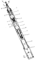
- the figure shows a longitudinal section of an embodiment of the device according to the invention for implanting a folded intraocular lens 15.
- the intraocular lens 15 is in the folded state in a tubular implant tool 19.
- the inner diameter of this tubular implant tool 19 is the thickness and the diameter or the cross-sectional shape the folded intraocular lens 15, which in particular a silicone lens is adapted.
- the tubular implantation tool is inserted in a conical adapter insert 16.
- This adapter insert 16 can be connected to the device to be explained in more detail, which can be referred to as a manipulator.
- the adapter insert 16 has two claws 18, which can be locked in their position in a housing head 14 of the tubular housing 9 of the device.
- the conical adapter insert 16 is then finally fixed to the housing 9 with the aid of an attached nut 17.
- a thrust device in the longitudinal direction of the implantation tool 19, ie along a common axis A. consisting of a push rod 12 and a plunger 20.
- the push rod 12 is guided via a miniature ball bearing 13 exactly in the housing head 14 in the longitudinal direction, ie in the direction of the axis A.
- a plunger 20 which can be provided in the conical adapter insert 16 or in the implantation tool 19.
- This plunger which is adapted to the cross section of the tube interior of the implantation tool 19, is made of a soft material, so that gentle treatment is ensured when the folded intraocular lens 15 in the implantation tool 19 is moved.
- the rod 12, the plunger 20 and the folded lens 15 are aligned with one another along the axis A.
- the manipulator has a rotary drive, which is designed in particular as an electric motor and, in the exemplary embodiment shown, as a DC micro-motor 1 which can be regulated at a speed.
- the micromotor can be fed with the aid of a battery 21.
- a planetary gear 2 is coupled to the micromotor 1.
- the rotary movement of the micromotor 1 is further transmitted via a clutch 3 connected to the planetary gear 2, which is preferably designed as a helix clutch, to a spindle 4, which in the exemplary embodiment is designed as a miniature ball screw spindle, so that the spindle 4 rotates is transferred.
- the spindle 4 is overhung in a bearing housing 6 via two ball bearings 5, in particular radial deep groove ball bearings, and is secured in the axial direction.
- the bearing housing 6 is screwed onto the tubular manipulator housing 9.
- the spindle 4 is part of a spindle-nut drive.
- the spindle 4 is guided in a ball nut 7 of the spindle-nut drive.
- the ball nut 7 is screwed to a sleeve 8.
- the sleeve 8 is longitudinally guided on the tubular manipulator housing 9 with the aid of pins 10.
- the pins 10 protrude into the interior of the tubular housing 9.
- the rotational movement of the spindle 4, which in the illustrated embodiment is preferably designed as a ball rolling spindle, is guided in a known manner in an internal thread of the ball nut 7, so that the rotation of the spindle 4 in a longitudinal movement the ball nut 7 is implemented.
- the longitudinal movement of the ball nut 7 is transmitted to the sleeve 8, which in the manner described with the aid of the fixed pins 10 in the interior of the tubular manipulator housing in the longitudinal direction, i.e. is guided in the direction of the axis A.
- the fixed pins 10 slide in the longitudinal grooves 23 of the sleeve 8.
- the linear movement in the axial direction A of the sleeve 8 is transmitted via a further coupling 11, which is also preferably designed as a helix coupling, to the push rod 12, which is mounted in the housing head 14 via the miniature ball bearing 13.
- the push rod 12 can be moved in the forward direction at a maximum feed speed of about 1 mm / sec, so that the folded intraocular lens 15 is pushed out of the implantation tool 19 into the lens capsule.
- the backward movement of the push rod 12 can be brought about by changing the direction of rotation of the DC voltage micromotor 1. The push rod 12 is then returned to its starting position.
- all bushings are preferably O-ring sealed.
- the total longitudinal extent of the device shown in the figure is approximately 215 mm.
- the length of the implant tool 19 protruding from the adapter insert 16 is approximately 10 mm.
- the feed S of the feed rod 12 is therefore also dimensioned to approximately 10 mm.
- the length of the adapter insert 16 placed on the manipulator together with the implantation tool 19 is approximately 27 mm.
- the diameter of the manipulator in the area of the battery 21 is approximately 20 mm.
Abstract
Description
Die Erfindung betrifft eine Vorrichtung zum Implantieren einer gefalteten Intraokularlinse aus gummielastischem Material, insbesondere Silikonlinse, mit einem röhrchenförmigen Gehäuse, einer im Gehäuse in Gehäuse-Längsrichtung geführten Schubstange, einem Drehantrieb zur Erzeugung einer Drehbewegung mit einem am einen Gehäuseende angeordneten Implantierwerkzeug, mit dem die gefaltete Linse durch eine Schnittöffnung im Auge in die Linsenkapsel des Auges einsetzbar ist, und mit einem Stößel am zum Implantierwerkzeug gekehrten Ende der Schubstange, der durch Verschieben der Schubstange in Richtung Implantierwerkzeug die Intraokularlinse vom Implantierwerkzeug trennt.The invention relates to a device for implanting a folded intraocular lens made of rubber-elastic material, in particular silicone lens, with a tubular housing, a push rod guided in the housing in the longitudinal direction of the housing, a rotary drive for generating a rotary movement with an implantation tool arranged at one end of the housing, with which the folded Lens can be inserted through a cut opening in the eye into the lens capsule of the eye, and with a plunger on the end of the push rod facing the implant tool, which pushes the push rod in the direction of the implant tool to separate the intraocular lens from the implant tool.
Eine Vorrichtung dieser Art ist durch die EP-A-0 363 213 bekannt. Als Drehantrieb dient bei dieser Vorrichtung ein getrennt vom röhrchenförmigen Gehäuse angeordneter und über eine elastische Welle mit dem Gehäuse gekoppelter Zahnstangentrieb. Das Implantierwerkzeug ist als Greifwerkzeug mit Backen und Zangen zum Greifen und Fassen der Intraokularlinse ausgebildet, dessen freies Ende samt gefalteter Intraokularlinse in die Schnittöffnung im Auge eingesetzt wird, wobei nach erfolgtem Einsatz in die Linsenkapsel durch Rotation der Vorrichtung die Intraokularlinse freigegeben wird, so daß diese in ihre ursprüngliche Linsenform zurückspringen kann.A device of this type is known from EP-A-0 363 213. In this device, a rack and pinion drive which is arranged separately from the tubular housing and is coupled to the housing via an elastic shaft serves as the rotary drive. The implantation tool is designed as a gripping tool with jaws and pliers for gripping and gripping the intraocular lens, the free end of which is velvet folded intraocular lens is inserted into the cut opening in the eye, the intraocular lens being released after use in the lens capsule by rotating the device so that it can spring back into its original lens shape.
Hinsichtlich ihrer Konstruktion ist diese Vorrichtung und insbesondere ihr Implantierwerkzeug aufwendig. Die zur Freigabe der Intraokularlinse in der Linsenkapsel erforderliche Rotation der Vorrichtung birgt zudem eine nicht unerhebliche Gefahr, insbesondere kann sie bei ungeübter Handhabung zur Beschädigung der Linsenkapsel führen.With regard to its construction, this device and in particular its implantation tool is complex. The rotation of the device required to release the intraocular lens in the lens capsule also poses a not inconsiderable risk, in particular if it is inexperienced, it can damage the lens capsule.
Ähnliche Vorrichtungen mit Implantierwerkzeugen mit an ihren Enden speziell geformten Pinzetten für den Einsatz der gefalteten Intraokularlinse in die Linsenkapsel erweisen sich gleichfalls als mühsam in ihrer Handhabung.Similar devices with implantation tools with tweezers specially shaped at their ends for the use of the folded intraocular lens in the lens capsule also prove to be tedious to handle.
Aufgabe der Erfindung ist es demgegenüber, eine Vorrichtung der eingangs genannten Art so zu gestalten, daß sie beim Einsetzen der gefalteten Intraokularlinse in die Linsenkapsel bei einer Kataraktoperation sicher gehandhabt werden kann und unter Vermeidung jeglicher Rotation des Implantierwerkzeugs und damit unter Vermeidung jeglicher Gefahr einer Schädigung des Auges, insbesondere der Linsenkapsel arbeitet.The object of the invention, in contrast, is to design a device of the type mentioned in such a way that it can be safely handled when inserting the folded intraocular lens into the lens capsule during a cataract operation and while avoiding any rotation of the implantation tool and thus avoiding any risk of damage to the Eye, especially the lens capsule works.
Die Aufgabe wird erfindungsgemäß dadurch gelöst, daß als Drehantrieb im Gehäuse ein Spindel-Mutter-Trieb mit Spindel, Kugelmutter und Hülse angeordnet ist, dessen Drehbewegung auf die in der Kugelmutter geführte Spindel übertragbar ist, wobei die Kugelmutter mit der Hülse verschraubt und die Hülse mittels Führungselementen im Gehäuse linear geführt ist, so daß die Drehbewegung der Spindel in eine lineare Bewegung der Hülse umgewandelt wird, daß der Hülse zur Übertragung ihrer linearen Bewegung auf die Schubstange eine Kupplung, z.B. eine Helix-Kupplung nachgeordnet ist und daß das Implantierwerkzeug röhrchenförmig ist und einen an die gefaltete Linse angepaßten Innendurchmesser aufweist.The object is achieved in that a spindle-nut drive with spindle, ball nut and sleeve is arranged as a rotary drive in the housing, the rotational movement of which is transferable to the spindle guided in the ball nut, the ball nut being screwed to the sleeve and the sleeve by means of Guide elements in the housing is guided linearly, so that the rotational movement of the spindle in a linear movement of the sleeve is converted, that the sleeve for transmitting its linear movement to the push rod is followed by a coupling, for example a helix coupling, and that the implantation tool is tubular and has an inner diameter adapted to the folded lens.
Durch diese Vorrichtung wird ein sicheres Halten der gefalteten Linse aus gummielastischem Material im Inneren des röhrchenförmigen Implantierwerkzeugs gewährleistet. Ferner wird gewährleistet, daß die gefaltete Linse unter Ausschluß jeglicher Drehmomenteinwirkung auf sie einwandfrei und mit gezielter Führung in die Linsenkapsel eingesetzt wird, so daß sie sich dort entfalten kann und die gewünschte Stellung nach dem Entfalten in die ursprüngliche Linsenform in der Linsenkapsel einnimmt. Das Einsetzen der gefalteten Linse läßt sich in der Weise bewerkstelligen, daß nach dem Auffalten der Linse der Linsenäquator mit dem Äquator der Linsenkapsel übereinstimmt.This device ensures that the folded lens made of rubber-elastic material is held securely in the interior of the tubular implant tool. Furthermore, it is ensured that the folded lens, with the exclusion of any torque, is used correctly and with targeted guidance in the lens capsule, so that it can unfold there and assume the desired position after unfolding in the original lens shape in the lens capsule. The folded lens can be inserted in such a way that, after the lens has been unfolded, the lens equator matches the equator of the lens capsule.
Für unterschiedliche Stärken und Durchmesser der Intraokularlinsen können unterschiedliche Querschnitte und Querschnittsformen des Röhrcheninneren des Implantierwerkzeugs vorgesehen werden. In bevorzugter Weise kann das Implantierwerkzeug als sterilisierbarer Aufbewahrungsbehälter für die gefaltete Linse ausgebildet sein.Different cross-sections and cross-sectional shapes of the tube interior of the implantation tool can be provided for different strengths and diameters of the intraocular lenses. The implantation tool can preferably be designed as a sterilizable storage container for the folded lens.
Mit Hilfe eines Adaptereinsatzes, beispielsweise durch Arretierverschluß und/oder Schraubverschluß kann das Implantierwerkzeug in vorteilhafter Weise am Gehäuse des auch als Manipulator bezeichneten restlichen Teils der Vorrichtung befestigt werden. Der Adaptereinsatz kann hierfür ebenfalls an die unterschiedlichen Querschnitte und Querschnittsformen des Implantierwerkzeugs angepaßt sein.With the aid of an adapter insert, for example by means of a locking lock and / or screw lock, the implantation tool can advantageously be attached to the housing of the remaining part of the device, which is also referred to as a manipulator. For this purpose, the adapter insert can also be adapted to the different cross-sections and cross-sectional shapes of the implantation tool be.
Der Stößel kann hierzu in dem Adaptereinsatz angeordnet sein oder in dem röhrchenförmigen, insbesondere als Aufbewahrungsbehälter für die gefaltete Linse dienenden Implantierwerkzeug angeordnet sein.For this purpose, the plunger can be arranged in the adapter insert or can be arranged in the tubular implant tool, in particular serving as a storage container for the folded lens.
Eine gleichmäßige Schubbewegung der exakt im Gehäuse des Manipulators geführten Schubstange, beispielsweise mit einer ziemlich konstanten Vorschubgeschwindigkeit, die maximal 1 mm pro Sekunde betragen kann, erreicht man mit Hilfe eines Drehantriebs, der insbesondere ein in seiner Drehzahl regelbarer Gleichspannungs-Mikromotor sein kann. Die Drehbewegung des Drehantriebs wird über die im Manipulator, insbesondere zwischen Hülse und Schubstange angeordnete Kupplung in eine lineare bzw. Längsbewegung umgesetzt, die auf die Schubstange übertragen wird.A uniform pushing motion of the push rod guided exactly in the housing of the manipulator, for example with a fairly constant feed speed, which can be a maximum of 1 mm per second, can be achieved with the help of a rotary drive, which in particular can be a DC micromotor with adjustable speed. The rotary movement of the rotary drive is converted into a linear or longitudinal movement via the coupling arranged in the manipulator, in particular between the sleeve and the push rod, which is transmitted to the push rod.
Auf diese Weise wird ein exaktes Einsetzen der gefalteten Linse bei einfacher Handhabung erreicht.In this way, an exact insertion of the folded lens is achieved with simple handling.
In der Figur ist in schnittbildlicher Darstellung ein Ausführungsbeispiel der Erfindung dargestellt. Anhand dieser Figur wird die Erfindung noch näher erläutert.In the figure, an embodiment of the invention is shown in a sectional representation. The invention is explained in more detail with reference to this figure.
Die Figur zeigt in einem Längsschnitt ein Ausführungsbeispiel für die erfindungsgemäße Vorrichtung zum Implantieren einer gefalteten Intraokularlinse 15. Die Intraokularlinse 15 befindet sich in gefaltetem Zustand in einem röhrchenförmigen Implantierwerkzeug 19. Der Innendurchmesser dieses röhrchenförmigen Implantierwerkzeugs 19 ist an die Stärke und den Durchmesser bzw. die Querschnittsform der gefalteten Intraokularlinse 15, die insbesondere eine Silikonlinse ist, angepaßt. Das röhrchenförmige Implantationswerkzeug ist in einem kegelförmigen Adaptereinsatz 16 eingesetzt. Dieser Adaptereinsatz 16 kann mit der im einzelnen noch näher zu erläuternden Vorrichtung, die quasi als Manipulator bezeichnet werden kann, verbunden werden. Hierzu besitzt der Adaptereinsatz 16 zwei Klauen 18, die in einem Gehäusekopf 14 des rohrförmigen Gehäuses 9 der Vorrichtung in ihrer Lage fixiert arretierbar sind. Mit Hilfe einer aufgesetzten Mutter 17 erfolgt dann die endgültige Fixierung des kegelförmigen Adaptereinsatzes 16 am Gehäuse 9.The figure shows a longitudinal section of an embodiment of the device according to the invention for implanting a folded
Im Gehäusekopf 14 ist in Längsrichtung des Implantierwerkzeugs 19, d.h. entlang einer gemeinsamen Achse A eine Schubeinrichtung, bestehend aus einer Schubstange 12 und einem Stößel 20, geführt. Die Schubstange 12 wird über ein Miniaturkugellager 13 exakt im Gehäusekopf 14 in Längsrichtung, d.h. in Richtung der Achse A, geführt. Am vorderen freien ende der Schubstange befindet sich ein Stößel 20, der im kegelförmigen Adaptereinsatz 16 oder auch im Implantierwerkzeug 19 vorgesehen sein kann. Dieser Stößel, welcher an den Querschnitt des Röhrcheninneren des Implantierwerkzeugs 19 angepaßt ist, besteht aus einem weichen Material, damit beim Verschieben der gefalteten Intraokularlinse 15 im Implantierwerkzeug 19 eine schonende Behandlung gewährleistet wird. Die Stange 12, der Stößel 20 und die gefaltete Linse 15 sind längs der Achse A zueinander ausgerichtet.In the
Um die Vorschubbewegung der Schubstange 12 zu erhalten, besitzt der Manipulator einen Drehantrieb, der insbesondere als Elektromotor und beim dargestellten Ausführungsbeispiel als ein Drehzahl regelbarer Gleichspannungsmikromotor 1 ausgebildet ist. Mit Hilfe einer Batterie 21 kann der Mikromotor gespeist werden.In order to maintain the feed movement of the
An den Mikromotor 1 ist ein Planetengetriebe 2 gekoppelt. Die Drehbewegung des Mikromotors 1 wird ferner über eine an das Planetengetriebe 2 angeschlossene Kupplung 3, welche bevorzugt als Helix-Kupplung ausgebildet ist, an eine Spindel 4, die beim Ausführungsbeispiel als Miniatur-Kugelrollspindel ausgeführt ist, weitergeleitet, so daß die Spindel 4 in Drehung versetzt wird.A
Die Spindel 4 ist über zwei Kugellager 5, insbesondere Radial-Rillenkugellager, in einem Lagergehäuse 6 fliegend gelagert und in axialer Richtung gesichert. Das Lagergehäuse 6 ist am rohrförmigen Manipulatorgehäuse 9 festgeschraubt.The spindle 4 is overhung in a bearing
Zur Umwandlung der Drehbewegung der Spindel 4 in eine Längsbewegung ist die Spindel 4 Bestandteil eines Spindel-Mutter-Triebs. Die Spindel 4 ist hierzu in einer Kugelmutter 7 des Spindel-Mutter-Triebs geführt. Die Kugelmutter 7 ist mit einer Hülse 8 verschraubt. Die Hülse 8 ist am rohrförmigen Manipulatorgehäuse 9 mit Hilfe von Stiften 10 längsgeführt. Die Stifte 10 ragen in das Innere des rohrförmigen Gehäuses 9. Die Drehbewegung der Spindel 4, welche beim dargestellten Ausführungsbeispiel bevorzugt als Kugelrollspindel ausgebildet ist, wird in bekannter Weise in einem Innengewinde der Kugelmutter 7 geführt, so daß die Drehung der Spindel 4 in eine Längsbewegung der Kugelmutter 7 umgesetzt wird. Die Längsbewegung der Kugelmutter 7 wird auf die Hülse 8 übertragen, die in der beschriebenen Weise mit Hilfe der festeingesetzten Stifte 10 im Innern des rohrförmigen Manipulatorgehäuses in Längsrichtung, d.h. in Richtung der Achse A, geführt ist. Hierbei gleiten die festeingesetzten Stifte 10 in Längsnuten 23 der Hülse 8.To convert the rotary movement of the spindle 4 into a longitudinal movement, the spindle 4 is part of a spindle-nut drive. For this purpose, the spindle 4 is guided in a ball nut 7 of the spindle-nut drive. The ball nut 7 is screwed to a
Die lineare Bewegung in axialer Richtung A der Hülse 8 wird über eine weitere Kupplung 11, die ebenfalls in bevorzugter Weise als Helix-Kupplung ausgebildet ist, auf die Schubstange 12, welche über das Miniaturkugellager 13 im Gehäusekopf 14 gelagert ist, übertragen.The linear movement in the axial direction A of the
Die Schubstange 12 kann mit einer maximalen Vorschubgeschwindigkeit von etwa 1 mm/sec in Vorwärtsrichtung bewegt werden, so daß dabei die gefaltete Intraokularlinse 15 aus dem Implantierwerkzeug 19 in die Linsenkapsel eingeschoben wird.The
Die Rückwärtsbewegung der Schubstange 12 läßt sich durch Drehrichtungsänderung des Gleichspannungsmikromotors 1 herbeiführen. Die Schubstange 12 wird dabei wieder in ihre Ausgangsposition zurückgestellt.The backward movement of the
Damit der Manipulator dampfsterilisiert werden kann, sind in bevorzugter Weise sämtliche Durchführungen O-Ring-gedichtet.So that the manipulator can be steam sterilized, all bushings are preferably O-ring sealed.
Die gesamte Längsausdehnung der in der Figur dargestellten Vorrichtung beträgt etwa 215 mm. Die aus dem Adaptereinsatz 16 herausragende Länge des Implantierwerkzeugs 19 beträgt etwa 10 mm. Mithin ist auch der Vorschub S der Vorschubstange 12 auf etwa 10 mm bemessen. Die Länge des auf den Manipulator aufgesetzten Adaptereinsatzes 16 zusammen mit dem Implantierwerkzeug 19 beträgt etwa 27 mm. Der Durchmesser des Manipulators beträgt im Bereich der Batterie 21 etwa 20 mm.The total longitudinal extent of the device shown in the figure is approximately 215 mm. The length of the
Claims (10)
- An apparatus for implanting a folded intraocular lens of material having rubber-like elasticity, in particular a silicone lens, said apparatus having a tubular housing (9) with a push-rod (12) guided within said housing along the longitudinal direction of said housing, a rotary drive for generating a rotary movement, an implantation tool (19) disposed on one housing end, with which the folded lens is insertable into the lens capsule of the eye through a cut opening in the eye, and having a plunger (20) on the end of the push rod (12) facing the implantation tool for separating the intraocular lens from the implantation tool (13) by displacement of the push rod (12) in the direction towards the implantation tool (19),
characterized in that
a spindle-nut drive (22) with spindle (4), ball nut (7) and sleeve (8) is disposed in the housing (9) as the rotary drive, the rotary movement of which is transmittable to the spindle (4) guided in the ball nut (7), the ball nut (7) being screwed to the sleeve (8) and the sleeve (8) being guided linearly in the housing (9) by means of guide members (10, 23), so that the rotary movement of the spindle (4) is transformed into a linear movement of the sleeve (8), that a coupling (11) is disposed in succession to the sleeve (8) for transmitting the linear movement thereof to the push-rod (12), and that the implantation tool (19) is of tubular shape and has an inner diameter which is conformed to the folded lens (15). - An apparatus according to claim 1, characterized in that the plunger (20) is conformed to the cross-section of the tubular inside of the implantation tool (19).
- An apparatus according to any one of claims 1 and 2, characterized in that the implantation tool (19) is adapted to be attached to the housing (9, 14) through an adapter insert (16).
- An apparatus according to any one of claims 1 to 3, characterized in that the implantation tool (19) is designed as a sterilized storage receptacle for the lens (15).
- An apparatus according to any one of claims 1 to 4, characterized in that the plunger (20) is disposed in the adapter insert (16).
- An apparatus according to any one of claims 1 to 5, characterized in that, for the linear guidance of the sleeve (8) in the housing (9), pins (10) are firmly inserted in the housing, said pins projecting into the tubular inside of the housing and sliding in longitudinal grooves (23) of the sleeve (8).
- An apparatus according to any one of claims 1 to 6, characterized in that the coupling (11) is disposed between sleeve (8) and push-rod (12).
- An apparatus according to any one of claims 1 to 7, characterized in that the coupling (11) is designed as a helix coupling.
- An apparatus according to any one of claims 1 to 8, characterized in that the advancing speed of the push rod (12) together with the plunger (20) is approx. 1 mm per second.
- An apparatus according to any one of claims 1 to 9, characterized in that the advancement distance of the push-rod (12) together with the plunger (20) is approx. 10 mm.
Applications Claiming Priority (2)
| Application Number | Priority Date | Filing Date | Title |
|---|---|---|---|
| DE4030492A DE4030492C1 (en) | 1990-09-26 | 1990-09-26 | |
| DE4030492 | 1990-09-26 |
Publications (2)
| Publication Number | Publication Date |
|---|---|
| EP0477466A1 EP0477466A1 (en) | 1992-04-01 |
| EP0477466B1 true EP0477466B1 (en) | 1996-06-26 |
Family
ID=6415044
Family Applications (1)
| Application Number | Title | Priority Date | Filing Date |
|---|---|---|---|
| EP91107164A Expired - Lifetime EP0477466B1 (en) | 1990-09-26 | 1991-05-03 | Device for implanting a folded intraocular lens of elastic rubber material particularly a silicone lens |
Country Status (4)
| Country | Link |
|---|---|
| US (1) | US5354333A (en) |
| EP (1) | EP0477466B1 (en) |
| AT (1) | ATE139682T1 (en) |
| DE (2) | DE4030492C1 (en) |
Cited By (7)
| Publication number | Priority date | Publication date | Assignee | Title |
|---|---|---|---|---|
| US8308736B2 (en) | 2008-10-13 | 2012-11-13 | Alcon Research, Ltd. | Automated intraocular lens injector device |
| US8308799B2 (en) | 2010-04-20 | 2012-11-13 | Alcon Research, Ltd. | Modular intraocular lens injector device |
| US8579969B2 (en) | 2010-07-25 | 2013-11-12 | Alcon Research, Ltd. | Dual mode automated intraocular lens injector device |
| US8657835B2 (en) | 2012-01-27 | 2014-02-25 | Alcon Research, Ltd. | Automated intraocular lens injector device |
| US8801780B2 (en) | 2008-10-13 | 2014-08-12 | Alcon Research, Ltd. | Plunger tip coupling device for intraocular lens injector |
| US8808308B2 (en) | 2008-10-13 | 2014-08-19 | Alcon Research, Ltd. | Automated intraocular lens injector device |
| US8894664B2 (en) | 2008-02-07 | 2014-11-25 | Novartis Ag | Lens delivery system cartridge |
Families Citing this family (59)
| Publication number | Priority date | Publication date | Assignee | Title |
|---|---|---|---|---|
| US5653715A (en) * | 1993-03-09 | 1997-08-05 | Chiron Vision Corporation | Apparatus for preparing an intraocular lens for insertion |
| US5468246A (en) * | 1993-07-02 | 1995-11-21 | Iovision, Inc. | Intraocular lens injector |
| DE19538951C2 (en) | 1995-10-19 | 1998-04-30 | Detlef H Dr Holzwig | Device for spreading an eye iris |
| US5693057A (en) * | 1995-10-27 | 1997-12-02 | Dusek; Vaclav | Instrument for implanting foldable intraocular lenses |
| US6179843B1 (en) | 1997-06-28 | 2001-01-30 | Harold H. Weiler | Device for insertion of foldable intraocular lenses |
| US6605093B1 (en) | 1997-10-24 | 2003-08-12 | Tekia, Inc. | Device and method for use with an ophthalmologic insertor apparatus |
| AU7361898A (en) | 1997-10-24 | 1999-05-17 | Tekia, Inc. | Ophthalmologic insertor apparatus and methods of use |
| US6050999A (en) * | 1997-12-18 | 2000-04-18 | Keravision, Inc. | Corneal implant introducer and method of use |
| DE19807233A1 (en) | 1998-02-20 | 1999-08-26 | Acritec Gmbh | Device for implanting an intraocular lens |
| DE19904220C2 (en) | 1999-02-03 | 2001-08-30 | Helmut Binder | Injector for folding and inserting an intraocular lens, and containers for storing and transporting the injector |
| US6283976B1 (en) * | 2000-05-05 | 2001-09-04 | Allergan Sales Inc. | Intraocular lens implanting instrument |
| US6500181B1 (en) * | 2000-10-17 | 2002-12-31 | Valdemar Portney | Instrument for folding and inserting anterior chamber intraocular lenses |
| EP1287791B1 (en) * | 2001-08-23 | 2009-09-09 | Anton Meyer & Co. AG | Device for implanting a lens into an eye |
| JP4138428B2 (en) * | 2002-09-27 | 2008-08-27 | 株式会社ニデック | Intraocular lens insertion device |
| ES2269644T3 (en) * | 2002-11-18 | 2007-04-01 | ANTON MEYER & CO.AG | DEVICE FOR THE INTRODUCTION OF A SLOW WITH RING. |
| CA2562542A1 (en) * | 2004-04-22 | 2005-11-03 | Advanced Vision Science, Inc. | Device for inserting deformable intraocular lenses |
| US8460311B2 (en) | 2004-12-27 | 2013-06-11 | Hoya Corporation | Intraocular lens implanting device |
| US20090125034A1 (en) * | 2004-12-29 | 2009-05-14 | Joel Pynson | Preloaded IOL Injector |
| US8545512B2 (en) | 2005-01-26 | 2013-10-01 | Hoya Corporation | Intraocular lens insertion device |
| JP4836046B2 (en) | 2005-02-24 | 2011-12-14 | Hoya株式会社 | Intraocular lens insertion device |
| US20090031839A1 (en) * | 2005-04-28 | 2009-02-05 | Namiki Seimitsu Houseki Kabushiki Kaisha | Motor shaft for micromotor, and micromotor |
| US20070005135A1 (en) * | 2005-07-01 | 2007-01-04 | Harish Makker | Intraocular lens insertion plunger with low stimulus soft tip |
| WO2007037223A1 (en) | 2005-09-28 | 2007-04-05 | Hoya Corporation | Instrument for inserting intraocular lens |
| JP4877643B2 (en) | 2005-12-08 | 2012-02-15 | Hoya株式会社 | Intraocular lens insertion device |
| NL2000082C2 (en) * | 2006-05-24 | 2007-11-27 | Akkolens Int Bv | Injector for implanting intraocular lens, moves lens with plunger along elongated guide towards exit opening in distal end of guide |
| US20080147082A1 (en) * | 2006-12-13 | 2008-06-19 | Joel Pynson | Injector apparatus for use with intraocular lenses and methods of use |
| US7879090B2 (en) * | 2006-12-13 | 2011-02-01 | Bausch & Lomb Incorporated | Intraocular lens injector apparatus and methods of use |
| US20080154361A1 (en) * | 2006-12-22 | 2008-06-26 | Joel Pynson | Intraocular lens injector subassembly |
| EP2161004B1 (en) | 2007-05-30 | 2017-12-27 | Hoya Corporation | Intraocular lens inserting tool |
| JP5236638B2 (en) | 2007-05-30 | 2013-07-17 | Hoya株式会社 | Intraocular lens insertion device |
| JP5086713B2 (en) | 2007-07-11 | 2012-11-28 | Hoya株式会社 | Intraocular lens insertion device |
| US8968396B2 (en) | 2007-07-23 | 2015-03-03 | Powervision, Inc. | Intraocular lens delivery systems and methods of use |
| US8668734B2 (en) | 2010-07-09 | 2014-03-11 | Powervision, Inc. | Intraocular lens delivery devices and methods of use |
| JP5426547B2 (en) | 2007-07-23 | 2014-02-26 | パワーヴィジョン・インコーポレーテッド | Lens delivery system |
| JP5254669B2 (en) | 2008-06-05 | 2013-08-07 | Hoya株式会社 | Intraocular lens insertion device and cartridge |
| JP5470753B2 (en) | 2008-06-17 | 2014-04-16 | Hoya株式会社 | Intraocular lens insertion device |
| JP5323420B2 (en) | 2008-08-21 | 2013-10-23 | Hoya株式会社 | Intraocular lens insertion device |
| JP5416379B2 (en) | 2008-09-04 | 2014-02-12 | Hoya株式会社 | Intraocular lens insertion device |
| SG172876A1 (en) | 2009-01-07 | 2011-08-29 | Hoya Corp | Intraocular lens insertion device |
| US8545554B2 (en) * | 2009-01-16 | 2013-10-01 | Allergan, Inc. | Intraocular injector |
| SG173546A1 (en) | 2009-02-11 | 2011-09-29 | Alcon Res Ltd | Automated intraocular lens injector device |
| WO2011126144A1 (en) | 2010-04-08 | 2011-10-13 | Hoya Corporation | Ocular implant insertion apparatus and methods |
| JP5511530B2 (en) | 2010-06-10 | 2014-06-04 | Hoya株式会社 | Intraocular lens insertion device |
| US8535268B2 (en) | 2010-12-22 | 2013-09-17 | Alcon Research, Ltd. | Device for at least one of injection or aspiration |
| ES2875049T3 (en) | 2011-03-24 | 2021-11-08 | Alcon Inc | Intraocular lens loading systems and methods of use |
| US9724191B2 (en) * | 2012-06-04 | 2017-08-08 | Alcon Pharmaceuticals, Ltd. | Intraocular lens inserter |
| WO2013188595A1 (en) | 2012-06-12 | 2013-12-19 | Altaviz, Llc | Intraocular gas injector |
| EP3785668A1 (en) | 2013-03-15 | 2021-03-03 | Alcon Inc. | Intraocular lens storage and loading devices and methods of use |
| US9480555B2 (en) * | 2013-04-03 | 2016-11-01 | Novartis Ag | Automated intraocular lens injector device |
| WO2015154049A1 (en) | 2014-04-04 | 2015-10-08 | Altaviz, Llc | Intraocular lens inserter |
| US9636217B2 (en) | 2014-05-08 | 2017-05-02 | Novartis Ag | Equipment and methods used in folding and implanting foldable lenses in the eye |
| JP6646987B2 (en) | 2015-09-16 | 2020-02-14 | Hoya株式会社 | Intraocular lens insertion device |
| AU2016324545A1 (en) | 2015-09-16 | 2018-04-12 | Hoya Corporation | Intraocular lens insertion tool |
| US10172706B2 (en) * | 2015-10-31 | 2019-01-08 | Novartis Ag | Intraocular lens inserter |
| US10722347B2 (en) * | 2015-12-17 | 2020-07-28 | Atrion Medical Products, Inc. | Intraocular lens delivery device and method of use |
| US11547555B2 (en) | 2015-12-17 | 2023-01-10 | Atrion Medical Products, Inc. | Intraocular lens delivery device and method of use |
| US11033382B2 (en) | 2016-06-28 | 2021-06-15 | Hoya Corporation | Intraocular lens injector |
| US11000367B2 (en) | 2017-01-13 | 2021-05-11 | Alcon Inc. | Intraocular lens injector |
| US11224537B2 (en) | 2018-10-19 | 2022-01-18 | Alcon Inc. | Intraocular gas injector |
Family Cites Families (7)
| Publication number | Priority date | Publication date | Assignee | Title |
|---|---|---|---|---|
| US4108182A (en) * | 1977-02-16 | 1978-08-22 | Concept Inc. | Reciprocation vitreous suction cutter head |
| DE2834299C2 (en) * | 1978-08-04 | 1982-08-19 | Deutsche Star Kugelhalter Gmbh, 8720 Schweinfurt | Ball screw drive |
| US4573998A (en) * | 1982-02-05 | 1986-03-04 | Staar Surgical Co. | Methods for implantation of deformable intraocular lenses |
| US4681102A (en) * | 1985-09-11 | 1987-07-21 | Bartell Michael T | Apparatus and method for insertion of an intra-ocular lens |
| US4834094A (en) * | 1987-10-07 | 1989-05-30 | Patton Medical Technologies, Inc. | "Canoe" apparatus for inserting intra-ocular lens into the eye |
| US4834095A (en) * | 1988-02-16 | 1989-05-30 | Ipco Corporation | Probe unit for electro-surgical device |
| JPH02156943A (en) * | 1988-10-07 | 1990-06-15 | Ioptex Res Inc | Lens inserting means in eye |
-
1990
- 1990-09-26 DE DE4030492A patent/DE4030492C1/de not_active Expired - Fee Related
-
1991
- 1991-05-03 EP EP91107164A patent/EP0477466B1/en not_active Expired - Lifetime
- 1991-05-03 AT AT91107164T patent/ATE139682T1/en not_active IP Right Cessation
- 1991-05-03 DE DE59107956T patent/DE59107956D1/en not_active Expired - Fee Related
-
1992
- 1992-11-20 US US07/979,368 patent/US5354333A/en not_active Expired - Fee Related
Cited By (7)
| Publication number | Priority date | Publication date | Assignee | Title |
|---|---|---|---|---|
| US8894664B2 (en) | 2008-02-07 | 2014-11-25 | Novartis Ag | Lens delivery system cartridge |
| US8308736B2 (en) | 2008-10-13 | 2012-11-13 | Alcon Research, Ltd. | Automated intraocular lens injector device |
| US8801780B2 (en) | 2008-10-13 | 2014-08-12 | Alcon Research, Ltd. | Plunger tip coupling device for intraocular lens injector |
| US8808308B2 (en) | 2008-10-13 | 2014-08-19 | Alcon Research, Ltd. | Automated intraocular lens injector device |
| US8308799B2 (en) | 2010-04-20 | 2012-11-13 | Alcon Research, Ltd. | Modular intraocular lens injector device |
| US8579969B2 (en) | 2010-07-25 | 2013-11-12 | Alcon Research, Ltd. | Dual mode automated intraocular lens injector device |
| US8657835B2 (en) | 2012-01-27 | 2014-02-25 | Alcon Research, Ltd. | Automated intraocular lens injector device |
Also Published As
| Publication number | Publication date |
|---|---|
| DE59107956D1 (en) | 1996-08-01 |
| DE4030492C1 (en) | 1991-09-05 |
| US5354333A (en) | 1994-10-11 |
| ATE139682T1 (en) | 1996-07-15 |
| EP0477466A1 (en) | 1992-04-01 |
Similar Documents
| Publication | Publication Date | Title |
|---|---|---|
| EP0477466B1 (en) | Device for implanting a folded intraocular lens of elastic rubber material particularly a silicone lens | |
| DE10358554B4 (en) | Surgical instrument for dissecting bones or other tissue with telescopic attachment | |
| DE3640420C2 (en) | ||
| EP2032088B1 (en) | Insertion instrument for joint sockets of prostheses | |
| DE2838348A1 (en) | DEVICE FOR MOLDING A BONE OPENING, IN PARTICULAR IN THE HIP LEG, FOR INSERTING AN ARTIFICIAL JOINT PAN | |
| EP1330192B1 (en) | Drilling tool for a surgical drill | |
| DE2834295B2 (en) | Device for producing a lateral surface that tapers conically from the frontal end section of a bone | |
| EP0317503A2 (en) | Device with a hollow milling cutter linked in rotation to a primary shaft, used to draw a sample of cartilage or bone | |
| EP0222971A1 (en) | Screw driver, especially for surgical purposes | |
| EP1605837A1 (en) | Coupling for a surgical rotary drive tool holder | |
| DE4103663A1 (en) | Surgical instrument with chuck - has quick clamping device which enables tool to rotate with driving shaft but free to move axially | |
| DE102014224591A1 (en) | Tool attachment and tool system | |
| DE4414903A1 (en) | Surgical instrument with tubular shaft for arthroscopy | |
| EP0670149B2 (en) | Straight motor-driven hand piece, in particular for medical applications, preferably for a medical or dental laboratory | |
| DE3117795C2 (en) | ||
| DE102005016869A1 (en) | Medical handpiece with a collet | |
| EP0505599B1 (en) | Clamping device, in particular for dental tools | |
| DE2735358A1 (en) | TOOL CHUCK FOR CLAMPING A TOOL WITH A VERY SMALL DIAMETER USING A DRIVER WITH A SPEED REDUCER FOR SURGICAL PURPOSES | |
| EP0420057A1 (en) | Focusing of objects of endoscopes | |
| DE4445598A1 (en) | Hand-held machine tool | |
| DE2937885C2 (en) | Dental handpiece | |
| DE19737238C2 (en) | Wave head, especially for flexible waves | |
| DE2020449A1 (en) | Keyless multi-jaw chuck | |
| DE3110348A1 (en) | CHUCK FOR A TURNING TOOL | |
| DE102004006772B4 (en) | Wrench |
Legal Events
| Date | Code | Title | Description |
|---|---|---|---|
| PUAI | Public reference made under article 153(3) epc to a published international application that has entered the european phase |
Free format text: ORIGINAL CODE: 0009012 |
|
| AK | Designated contracting states |
Kind code of ref document: A1 Designated state(s): AT BE CH DE DK ES FR GB GR IT LI LU NL SE |
|
| 17P | Request for examination filed |
Effective date: 19920319 |
|
| 17Q | First examination report despatched |
Effective date: 19940705 |
|
| RAP1 | Party data changed (applicant data changed or rights of an application transferred) |
Owner name: CHIRON ADATOMED PHARMAZEUTISCHE UND MEDIZINTECHNIS |
|
| GRAH | Despatch of communication of intention to grant a patent |
Free format text: ORIGINAL CODE: EPIDOS IGRA |
|
| GRAA | (expected) grant |
Free format text: ORIGINAL CODE: 0009210 |
|
| AK | Designated contracting states |
Kind code of ref document: B1 Designated state(s): AT BE CH DE DK ES FR GB GR IT LI LU NL SE |
|
| PG25 | Lapsed in a contracting state [announced via postgrant information from national office to epo] |
Ref country code: IT Free format text: LAPSE BECAUSE OF FAILURE TO SUBMIT A TRANSLATION OF THE DESCRIPTION OR TO PAY THE FEE WITHIN THE PRE;WARNING: LAPSES OF ITALIAN PATENTS WITH EFFECTIVE DATE BEFORE 2007 MAY HAVE OCCURRED AT ANY TIME BEFORE 2007. THE CORRECT EFFECTIVE DATE MAY BE DIFFERENT FROM THE ONE RECORDED.SCRIBED TIME-LIMIT Effective date: 19960626 Ref country code: FR Effective date: 19960626 Ref country code: GR Free format text: LAPSE BECAUSE OF FAILURE TO SUBMIT A TRANSLATION OF THE DESCRIPTION OR TO PAY THE FEE WITHIN THE PRESCRIBED TIME-LIMIT Effective date: 19960626 Ref country code: GB Effective date: 19960626 Ref country code: NL Free format text: LAPSE BECAUSE OF FAILURE TO SUBMIT A TRANSLATION OF THE DESCRIPTION OR TO PAY THE FEE WITHIN THE PRESCRIBED TIME-LIMIT Effective date: 19960626 Ref country code: ES Free format text: THE PATENT HAS BEEN ANNULLED BY A DECISION OF A NATIONAL AUTHORITY Effective date: 19960626 Ref country code: DK Effective date: 19960626 |
|
| REF | Corresponds to: |
Ref document number: 139682 Country of ref document: AT Date of ref document: 19960715 Kind code of ref document: T |
|
| REF | Corresponds to: |
Ref document number: 59107956 Country of ref document: DE Date of ref document: 19960801 |
|
| PG25 | Lapsed in a contracting state [announced via postgrant information from national office to epo] |
Ref country code: SE Effective date: 19960926 |
|
| EN | Fr: translation not filed | ||
| NLV1 | Nl: lapsed or annulled due to failure to fulfill the requirements of art. 29p and 29m of the patents act | ||
| GBV | Gb: ep patent (uk) treated as always having been void in accordance with gb section 77(7)/1977 [no translation filed] |
Effective date: 19960626 |
|
| PLBE | No opposition filed within time limit |
Free format text: ORIGINAL CODE: 0009261 |
|
| STAA | Information on the status of an ep patent application or granted ep patent |
Free format text: STATUS: NO OPPOSITION FILED WITHIN TIME LIMIT |
|
| PG25 | Lapsed in a contracting state [announced via postgrant information from national office to epo] |
Ref country code: AT Free format text: LAPSE BECAUSE OF NON-PAYMENT OF DUE FEES Effective date: 19970503 |
|
| PG25 | Lapsed in a contracting state [announced via postgrant information from national office to epo] |
Ref country code: LU Free format text: LAPSE BECAUSE OF NON-PAYMENT OF DUE FEES Effective date: 19970531 Ref country code: BE Effective date: 19970531 Ref country code: CH Free format text: LAPSE BECAUSE OF NON-PAYMENT OF DUE FEES Effective date: 19970531 Ref country code: LI Free format text: LAPSE BECAUSE OF NON-PAYMENT OF DUE FEES Effective date: 19970531 |
|
| 26N | No opposition filed | ||
| BERE | Be: lapsed |
Owner name: CHIRON ADATOMED PHARMAZEUTISCHE UND MEDIZINTECHNI Effective date: 19970531 |
|
| REG | Reference to a national code |
Ref country code: CH Ref legal event code: PL |
|
| PG25 | Lapsed in a contracting state [announced via postgrant information from national office to epo] |
Ref country code: DE Free format text: LAPSE BECAUSE OF NON-PAYMENT OF DUE FEES Effective date: 19980203 |