EP0478624B1 - Apparatus for making or dispensing drinks - Google Patents
Apparatus for making or dispensing drinks Download PDFInfo
- Publication number
- EP0478624B1 EP0478624B1 EP90909341A EP90909341A EP0478624B1 EP 0478624 B1 EP0478624 B1 EP 0478624B1 EP 90909341 A EP90909341 A EP 90909341A EP 90909341 A EP90909341 A EP 90909341A EP 0478624 B1 EP0478624 B1 EP 0478624B1
- Authority
- EP
- European Patent Office
- Prior art keywords
- wall
- valve
- concentrate
- wall means
- chamber
- Prior art date
- Legal status (The legal status is an assumption and is not a legal conclusion. Google has not performed a legal analysis and makes no representation as to the accuracy of the status listed.)
- Expired - Lifetime
Links
Images


Classifications
-
- B—PERFORMING OPERATIONS; TRANSPORTING
- B67—OPENING, CLOSING OR CLEANING BOTTLES, JARS OR SIMILAR CONTAINERS; LIQUID HANDLING
- B67D—DISPENSING, DELIVERING OR TRANSFERRING LIQUIDS, NOT OTHERWISE PROVIDED FOR
- B67D1/00—Apparatus or devices for dispensing beverages on draught
- B67D1/08—Details
- B67D1/12—Flow or pressure control devices or systems, e.g. valves, gas pressure control, level control in storage containers
- B67D1/1277—Flow control valves
- B67D1/1279—Flow control valves regulating the flow
-
- B—PERFORMING OPERATIONS; TRANSPORTING
- B67—OPENING, CLOSING OR CLEANING BOTTLES, JARS OR SIMILAR CONTAINERS; LIQUID HANDLING
- B67D—DISPENSING, DELIVERING OR TRANSFERRING LIQUIDS, NOT OTHERWISE PROVIDED FOR
- B67D1/00—Apparatus or devices for dispensing beverages on draught
- B67D1/0015—Apparatus or devices for dispensing beverages on draught the beverage being prepared by mixing at least two liquid components
- B67D1/0021—Apparatus or devices for dispensing beverages on draught the beverage being prepared by mixing at least two liquid components the components being mixed at the time of dispensing, i.e. post-mix dispensers
- B67D1/0022—Apparatus or devices for dispensing beverages on draught the beverage being prepared by mixing at least two liquid components the components being mixed at the time of dispensing, i.e. post-mix dispensers the apparatus comprising means for automatically controlling the amount to be dispensed
- B67D1/0034—Apparatus or devices for dispensing beverages on draught the beverage being prepared by mixing at least two liquid components the components being mixed at the time of dispensing, i.e. post-mix dispensers the apparatus comprising means for automatically controlling the amount to be dispensed for controlling the amount of each component
- B67D1/0039—Apparatus or devices for dispensing beverages on draught the beverage being prepared by mixing at least two liquid components the components being mixed at the time of dispensing, i.e. post-mix dispensers the apparatus comprising means for automatically controlling the amount to be dispensed for controlling the amount of each component the controls involving at least two different metering technics
-
- B—PERFORMING OPERATIONS; TRANSPORTING
- B67—OPENING, CLOSING OR CLEANING BOTTLES, JARS OR SIMILAR CONTAINERS; LIQUID HANDLING
- B67D—DISPENSING, DELIVERING OR TRANSFERRING LIQUIDS, NOT OTHERWISE PROVIDED FOR
- B67D1/00—Apparatus or devices for dispensing beverages on draught
- B67D1/0042—Details of specific parts of the dispensers
- B67D1/0057—Carbonators
- B67D1/0069—Details
- B67D1/0074—Automatic carbonation control
-
- B—PERFORMING OPERATIONS; TRANSPORTING
- B67—OPENING, CLOSING OR CLEANING BOTTLES, JARS OR SIMILAR CONTAINERS; LIQUID HANDLING
- B67D—DISPENSING, DELIVERING OR TRANSFERRING LIQUIDS, NOT OTHERWISE PROVIDED FOR
- B67D1/00—Apparatus or devices for dispensing beverages on draught
- B67D1/08—Details
- B67D1/12—Flow or pressure control devices or systems, e.g. valves, gas pressure control, level control in storage containers
- B67D1/1202—Flow control, e.g. for controlling total amount or mixture ratio of liquids to be dispensed
- B67D1/1204—Flow control, e.g. for controlling total amount or mixture ratio of liquids to be dispensed for ratio control purposes
- B67D1/1231—Metering pumps
-
- B—PERFORMING OPERATIONS; TRANSPORTING
- B67—OPENING, CLOSING OR CLEANING BOTTLES, JARS OR SIMILAR CONTAINERS; LIQUID HANDLING
- B67D—DISPENSING, DELIVERING OR TRANSFERRING LIQUIDS, NOT OTHERWISE PROVIDED FOR
- B67D1/00—Apparatus or devices for dispensing beverages on draught
- B67D1/08—Details
- B67D1/12—Flow or pressure control devices or systems, e.g. valves, gas pressure control, level control in storage containers
- B67D1/1284—Ratio control
- B67D1/1286—Ratio control by mechanical construction
- B67D1/129—Means for changing the ratio by acting on structural parts
Definitions
- the present invention relates to a device for discharging metered quantites of liquid concentrate
- a device for discharging metered quantites of liquid concentrate comprising a housing having wall means defining a hollow interior, a flexible member dividing the interior of the housing into a first chamber and a second chamber, inlet valve means in the communication with the first chamber for permitting the flow of concentrate therethrough into the first chamber when the inlet valve means is opened and the inlet valve being closable to resist reverse flow of concentrate therethrough, outlet valve means in communication with the first chamber for discharging concentrate therefrom, and gas inlet means in communication with the second chamber for the supply of gas thereto for pressurisation of said hollow interior to cause said flexible member to flex so as to discharge concentrate from the first chamber through said outlet valve means.
- US 4334640 discloses a device as described above in which the outlet valve means is provided by a tubular portion having a central bore in communication with a plurality of radial bores providing fluid communication between the chamber of the device which may contain concentrate and the exterior of the device.
- a thin resilient piece of hose is arranged to cover the openings of the plurality of radial bores, the resilience of the wall of the piece of hose being arranged to hold the wall in contact with the outlets of the radial bores to close the valve.
- the fluid pressure is such that concentrate may be pushed out of the device via the radial bores and deform the resilient piece of hose to open the valve and allow concentrate to flow from the device.
- the object of the present invention is, at least in the preferred embodiment, to provide an improved concentrate discharging device.
- the device according to the present invention is characterised in that the outlet valve means comprises an opening in a first portion of the wall means and a valve head carried by a second portion of said wall means, said first and second portions of said wall means being relatively moveable for effecting relative movement of the valve head and valve opening, and being resiliently biased to a first relative position in which the opening is closed by the valve head and being arranged to move in response to said pressurisation of the device to a second relative position in which the outlet valve means is opened.
- Figs. 1 to 8 show a concentrate supply device 2 comprising a concentrate container 4, such as a liquid tight box, and a concentrate dispensing unit 6 which is secured to the container 4, and is for dispensing concentrate therefrom in metered quantities.
- the container 4 is filled with liquid concentrate 8 to be dispensed although each of Figs. 1 to 4 show that the container 4 has already been partly emptied.
- the dispensing unit 6 comprises a cylindrical side wall 10 which is secured, as by welding, to a disc shaped upper wall 12 having an outwardly extending flange 14 by which the unit 6 is secured, again as by welding, to a wall 16 of the container 4.
- a lower wall 18 of the unit 6 is carried by the cylindrical wall 10 and has a central circular aperture 20 through which projects a stem 22, of circular cross-section, carried by the upper wall 12.
- a flexible plastics diaphragm 24 of relatively flimsy material is provided in the unit 6.
- the diaphragm 24, as best seen in Fig. 6, is of bag-like construction and is of a size and shape such that, as shown in Fig. 2, it may conform to the interior of the walls 10 and 18.
- the diaphragm is open at its upper end and the upper edge 26 thereof is secured between the walls 10 and 12.
- the diaphragm 24 has an opening 28 at its lower end and the perimeter of the opening 28 of the diaphragm is secured as by welding to the portion of the wall 18 surrounding the aperture 20.
- the diaphragm 24 accordingly divides the interior of the unit 6 into two chambers 30 and 32.
- the chamber 30 communicates with the interior of vessel 4 through a passage 34 which may be closed by a one-way valve 36 and the chamber 32 may receive pressurised gas from a gas supply (not shown) through a nipple 38 into which the end of a gas supply pipe 40 may be inserted.
- the wall 12, flanges 16 and stem 22 are formed as a first unitary plastics moulding and the wall 10, wall 18 and nipple 38 are formed as a second unitary plastics moulding, the two mouldings being secured together with the upper edge 26 of the diaphragm 24 clamped therebetween.
- the stem 22 is hollow to define a passage 42 which, at its lower end communicates with atmosphere, and its upper end may communicate with the interior of the container 4 through a passage 44 which may be closed by a one-way valve 46.
- a circumferential channel 48 is provided on the outside of stem 22 at a position near but spaced from the lower end.
- the size of the opening 20 in wall 18 is such that the wall 18 extends into the channel 48 and normally contacts the stem 20 at a point 50 therein to form a seal.
- Four axial channels 52 extend along the exterior of the portion of the stem 20 below the circumferential channel 50.
- the wall 18 is flexibly resilient so that it may bend from the full line position shown in Fig. 7 in which a seal is formed at point 50 to the chain dotted line position 54 shown in Fig. 7 in which the seal at point 50 is broken and contact is made with the stem at point 56 adjacent the upper end of the channel 52.
- the resilience of the wall 18 is sufficient to permit the lower part of stem 22 to be pushed through the aperture 20 during assembly.
- the valve 36 is made of a unitary moulding of synthetic plastics material and comprises a ball 60 forming a valve head, a ligament 62 extending through the passage 34 and a cross-bar 64 on the opposite side of the passage 36 to the head 60 and acting as a stop limiting the downwards movement of the head 60.
- the ligament 62 is sufficiently flexible to enable it to be bent so that the cross-bar 64 extends generally parallel to the ligament to enable the ligament and cross-bar to be threaded through the aperture 34 during manufacture.
- the construction of the valve 46 is identical to the valve 36 and thus comprises a head 70, ligament 72 and cross-bar 74.
- the device illustrated in Figs. 1 to 8 will normally be supplied to customers with the container 4 filled with concentrate and the metering unit 6 empty.
- a cap 76 shown in broken lines in Fig. 1 only is preferably included and is attached to the unit 6 by a breakable seal (not shown) and covers the lower end of the stem 22 and the nipple 38.
- the customer removes the cap 76 and inserts the device into a carbonating apparatus, not described herein in detail, which is designed for receiving the device 2.
- the device 2 is inserted in the carbonating apparatus in the "inverted" position illustrated in Figs. 1 to 4 and the pipe 40, which is part of the carbonation apparatus, is inserted into the nipple 38 and forms a gas tight seal therewith.
- the chamber 32 is not pressurised and, as a result, liquid may flow under gravity from the interior of the container 4 into the chamber 30, the valve 36 opening for this purpose as shown in Fig. 1.
- pressure within the container 4 may reduce and as a result atmospheric pressure acting on valve head 70 will cause the valve 46 to open to permit air to bubble up through the liquid in container 4 as indicated at 78 in Fig. 1.
- the air in the chamber 30 will first be transferred through the passage 34 into the container 4 as liquid enters the chamber 30, in which the case the opening of the valve 46 may be delayed.
- valve 46 closes.
- the unit 6 now contains a metered quantity of liquid to be dispensed.
- this metered quantity of liquid may be dispensed from the unit 6 by permitting gas pressure to enter chamber 32 through pipe 40.
- the admission of such gas is preferably controlled by a control and timing system (not shown) of the carbonation apparatus (not shown) with which the device 2 is used.
- a control and timing system not shown
- Such a device is disclosed in GB 2233960.
- the pressure in chamber 32 increases, the resulting tendency of the liquid in chamber 30 to be forced upwardly through the passage 34 causes the valve 36 to close (Fig. 3). This pressure also causes wall 18 to flex downwardly as shown in Fig.
- the pressure in chamber 32 is retained long enough to substantially empty the chamber 30 of liquid, at which point, as shown in Fig. 4, the diaphragm 24 has reduced the volume of chamber 30 to near to zero. Thereafter, the pressure in chamber 32 may be released and chamber 30 will again fill with concentrate as shown in Figs. 1 and 2;
- Figs. 9 to 11 The embodiment shown in Figs. 9 to 11 is the same as that of Figs. 1 to 8 except that the lower wall 18A of unit 6 is substantially rigid and, instead, the upper wall 12A is resiliently flexible and is thus somewhat thinner than the wall 12.
- Fig. 9 shows the chamber filled with liquid 30 to be dispensed and
- Fig. 10 shows the dispensing operation with the chamber 32 pressurised.
- the wall 12A flexes upwardly to draw the stem 20 upwardly with respect to the aperture 20 in wall 18A, thus permitting liquid to be discharged from the chamber 30 through aperture 20.
- the distance through which the stem 20 moves upwardly relative to the wall 18 depends upon the pressure in the chamber 32 so that, when the pressure is high, the liquid is constrained to flow through the restricted area defined by the edge of the wall 18A around the aperture 20 and the channels 52 whereas lower pressures cause the stem 20 to assume intermediate position at which the area available for the outflow of liquid is greater.
- the container 4 is of relatively rigid material in the illustrated embodiments, thus requiring provision for air to enter as the liquid leaves (this provision being the valve 46 in the embodiment shown in the drawings), the invention can be applied to so-called "bag-in-a-box" containers in which the liquid is contained in a collapsible bag located in a box. In this case, dispensing can be achieved without the need for air to enter the bag containing the liquid since this collapses under atmospheric pressure as liquid is withdrawn.
- the invention provides a highly advantageous and inexpensive device for dispensing concentrate which may be made sufficiently cheaply to be disposed of after the liquid in the container with which it is used has been consumed.
Abstract
Description
- The present invention relates to a device for discharging metered quantites of liquid concentrate comprising a housing having wall means defining a hollow interior, a flexible member dividing the interior of the housing into a first chamber and a second chamber, inlet valve means in the communication with the first chamber for permitting the flow of concentrate therethrough into the first chamber when the inlet valve means is opened and the inlet valve being closable to resist reverse flow of concentrate therethrough, outlet valve means in communication with the first chamber for discharging concentrate therefrom, and gas inlet means in communication with the second chamber for the supply of gas thereto for pressurisation of said hollow interior to cause said flexible member to flex so as to discharge concentrate from the first chamber through said outlet valve means.
- US 4334640 (van Overbruggen et al) discloses a device as described above in which the outlet valve means is provided by a tubular portion having a central bore in communication with a plurality of radial bores providing fluid communication between the chamber of the device which may contain concentrate and the exterior of the device. A thin resilient piece of hose is arranged to cover the openings of the plurality of radial bores, the resilience of the wall of the piece of hose being arranged to hold the wall in contact with the outlets of the radial bores to close the valve. At a predetermined pressurisation of the device, the fluid pressure is such that concentrate may be pushed out of the device via the radial bores and deform the resilient piece of hose to open the valve and allow concentrate to flow from the device.
- If the outlet valve of the device described in US 4334640 is to provide an adequate seal, the piece of hose would need to be tightly fitting and strongly elastic. The disadvantage of this is that the pressure change required to open the valve would be relatively large. If the device is to be operated by a lower pressure change then the hose would need to be relatively weak and the concentrate contained in the device would be likely to leak out under the static pressure of the concentrate in the dispensing tube.
- The object of the present invention is, at least in the preferred embodiment, to provide an improved concentrate discharging device.
- The device according to the present invention is characterised in that the outlet valve means comprises an opening in a first portion of the wall means and a valve head carried by a second portion of said wall means, said first and second portions of said wall means being relatively moveable for effecting relative movement of the valve head and valve opening, and being resiliently biased to a first relative position in which the opening is closed by the valve head and being arranged to move in response to said pressurisation of the device to a second relative position in which the outlet valve means is opened.
- Embodiments of the invention will now be described, by way of example only, with reference to the accompanying drawings, in which:-
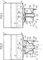
- Figs. 1 to 4 are diagrammatic cross-sectional views of a dispensing device according to an embodiment of the invention, showing the device in four different conditions;
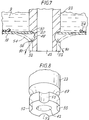
- Fig. 5 is a cross-section on the line V-V shown in Fig. 1;
- Fig. 6 is a perspective view, partly cut-away, of a part of the device of Figs. 1 to 5;
- Fig. 7 is an enlarged section through part of the device shown in Figs. 1 to 4;
- Fig. 8 is an enlarged perspective view of part of the device as shown in Fig. 7;
- Figs. 9 and 10 are views similar to Figs. 2 and 3 but showing an alternative embodiment of the invention; and
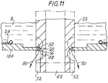
- Fig. 11 is an enlarged sectional view through part of the device shown in Figs. 9 and 10.
- Figs. 1 to 8 show a
concentrate supply device 2 comprising aconcentrate container 4, such as a liquid tight box, and aconcentrate dispensing unit 6 which is secured to thecontainer 4, and is for dispensing concentrate therefrom in metered quantities. Intially, thecontainer 4 is filled withliquid concentrate 8 to be dispensed although each of Figs. 1 to 4 show that thecontainer 4 has already been partly emptied. - The
dispensing unit 6 comprises acylindrical side wall 10 which is secured, as by welding, to a disc shapedupper wall 12 having an outwardly extendingflange 14 by which theunit 6 is secured, again as by welding, to awall 16 of thecontainer 4. Alower wall 18 of theunit 6 is carried by thecylindrical wall 10 and has a centralcircular aperture 20 through which projects astem 22, of circular cross-section, carried by theupper wall 12. Aflexible plastics diaphragm 24 of relatively flimsy material is provided in theunit 6. Thediaphragm 24, as best seen in Fig. 6, is of bag-like construction and is of a size and shape such that, as shown in Fig. 2, it may conform to the interior of thewalls upper edge 26 thereof is secured between thewalls diaphragm 24 has anopening 28 at its lower end and the perimeter of the opening 28 of the diaphragm is secured as by welding to the portion of thewall 18 surrounding theaperture 20. Thediaphragm 24 accordingly divides the interior of theunit 6 into twochambers chamber 30 communicates with the interior ofvessel 4 through apassage 34 which may be closed by a one-way valve 36 and thechamber 32 may receive pressurised gas from a gas supply (not shown) through anipple 38 into which the end of agas supply pipe 40 may be inserted. Preferably, thewall 12,flanges 16 andstem 22 are formed as a first unitary plastics moulding and thewall 10,wall 18 andnipple 38 are formed as a second unitary plastics moulding, the two mouldings being secured together with theupper edge 26 of thediaphragm 24 clamped therebetween. - The
stem 22 is hollow to define apassage 42 which, at its lower end communicates with atmosphere, and its upper end may communicate with the interior of thecontainer 4 through apassage 44 which may be closed by a one-way valve 46. - A
circumferential channel 48 is provided on the outside ofstem 22 at a position near but spaced from the lower end. The size of the opening 20 inwall 18 is such that thewall 18 extends into thechannel 48 and normally contacts thestem 20 at apoint 50 therein to form a seal. Fouraxial channels 52 extend along the exterior of the portion of thestem 20 below thecircumferential channel 50. Thewall 18 is flexibly resilient so that it may bend from the full line position shown in Fig. 7 in which a seal is formed atpoint 50 to the chain dottedline position 54 shown in Fig. 7 in which the seal atpoint 50 is broken and contact is made with the stem atpoint 56 adjacent the upper end of thechannel 52. The resilience of thewall 18 is sufficient to permit the lower part ofstem 22 to be pushed through theaperture 20 during assembly. - The
valve 36 is made of a unitary moulding of synthetic plastics material and comprises aball 60 forming a valve head, a ligament 62 extending through thepassage 34 and a cross-bar 64 on the opposite side of thepassage 36 to thehead 60 and acting as a stop limiting the downwards movement of thehead 60. The ligament 62 is sufficiently flexible to enable it to be bent so that the cross-bar 64 extends generally parallel to the ligament to enable the ligament and cross-bar to be threaded through theaperture 34 during manufacture. The construction of thevalve 46 is identical to thevalve 36 and thus comprises a head 70,ligament 72 andcross-bar 74. - The device illustrated in Figs. 1 to 8 will normally be supplied to customers with the
container 4 filled with concentrate and themetering unit 6 empty. Acap 76 shown in broken lines in Fig. 1 only is preferably included and is attached to theunit 6 by a breakable seal (not shown) and covers the lower end of thestem 22 and thenipple 38. In order to use the device, the customer removes thecap 76 and inserts the device into a carbonating apparatus, not described herein in detail, which is designed for receiving thedevice 2. Thedevice 2 is inserted in the carbonating apparatus in the "inverted" position illustrated in Figs. 1 to 4 and thepipe 40, which is part of the carbonation apparatus, is inserted into thenipple 38 and forms a gas tight seal therewith. At this point, thechamber 32 is not pressurised and, as a result, liquid may flow under gravity from the interior of thecontainer 4 into thechamber 30, thevalve 36 opening for this purpose as shown in Fig. 1. As liquid leaves the interior of thecontainer 4 and enters thechamber 30, pressure within thecontainer 4 may reduce and as a result atmospheric pressure acting on valve head 70 will cause thevalve 46 to open to permit air to bubble up through the liquid incontainer 4 as indicated at 78 in Fig. 1. Of course, if thechamber 30 is filled with air when the device is first used, the air in thechamber 30 will first be transferred through thepassage 34 into thecontainer 4 as liquid enters thechamber 30, in which the case the opening of thevalve 46 may be delayed. - As shown in Fig. 2, after the
chamber 30 has been filled with liquid concentrate from thecontainer 4,valve 46 closes. Theunit 6 now contains a metered quantity of liquid to be dispensed. As shown in Fig. 3, this metered quantity of liquid may be dispensed from theunit 6 by permitting gas pressure to enterchamber 32 throughpipe 40. The admission of such gas is preferably controlled by a control and timing system (not shown) of the carbonation apparatus (not shown) with which thedevice 2 is used. Such a device is disclosed in GB 2233960. As the pressure inchamber 32 increases, the resulting tendency of the liquid inchamber 30 to be forced upwardly through thepassage 34 causes thevalve 36 to close (Fig. 3). This pressure also causeswall 18 to flex downwardly as shown in Fig. 3 and in broken lines in Fig. 7, thus allowing liquid in thechamber 30 to be discharged therefrom through theopening 20 in thewall 18. If the pressure inchamber 32 is sufficiently high, thewall 18 will be bent to the chain dotted line position shown in Fig. 7 and the liquid leaving thechamber 32 will pass through the relatively small apertures defined by thechannels 52 and the edge of thewall 18 around the opening 20, as indicated byarrows 80 in Fig. 7. If the pressure is somewhat lower than that necessary to achieve this condition, contact will not be made atpoint 56 betweenwall 18 andstem 22 and as a result, the outflow of liquid will not be constricted by thechannels 52. In this way, variations in the rate of outflow of liquid as a result of pressure variations inchamber 32 may be reduced. - The pressure in
chamber 32 is retained long enough to substantially empty thechamber 30 of liquid, at which point, as shown in Fig. 4, thediaphragm 24 has reduced the volume ofchamber 30 to near to zero. Thereafter, the pressure inchamber 32 may be released andchamber 30 will again fill with concentrate as shown in Figs. 1 and 2; - The embodiment shown in Figs. 9 to 11 is the same as that of Figs. 1 to 8 except that the
lower wall 18A ofunit 6 is substantially rigid and, instead, theupper wall 12A is resiliently flexible and is thus somewhat thinner than thewall 12. Fig. 9 shows the chamber filled withliquid 30 to be dispensed and Fig. 10 shows the dispensing operation with thechamber 32 pressurised. As can be seen, thewall 12A flexes upwardly to draw thestem 20 upwardly with respect to theaperture 20 inwall 18A, thus permitting liquid to be discharged from thechamber 30 throughaperture 20. The distance through which thestem 20 moves upwardly relative to thewall 18 depends upon the pressure in thechamber 32 so that, when the pressure is high, the liquid is constrained to flow through the restricted area defined by the edge of thewall 18A around theaperture 20 and thechannels 52 whereas lower pressures cause thestem 20 to assume intermediate position at which the area available for the outflow of liquid is greater. - Various modifications are possible within the scope of the invention. For example, although it has been assumed that the
container 4 is of relatively rigid material in the illustrated embodiments, thus requiring provision for air to enter as the liquid leaves (this provision being thevalve 46 in the embodiment shown in the drawings), the invention can be applied to so-called "bag-in-a-box" containers in which the liquid is contained in a collapsible bag located in a box. In this case, dispensing can be achieved without the need for air to enter the bag containing the liquid since this collapses under atmospheric pressure as liquid is withdrawn. - The invention provides a highly advantageous and inexpensive device for dispensing concentrate which may be made sufficiently cheaply to be disposed of after the liquid in the container with which it is used has been consumed.
Claims (12)
- A device (2) for discharging metered quantities of liquid concentrate comprising a housing having wall means (10, 12, 18; 12A, 18A) defining a hollow interior (30, 32), a flexible member (24) dividing the interior (30, 32) of the housing into a first chamber (30) and a second chamber (32), inlet valve means (36) in communication with the first chamber (30) for permitting flow of concentrate therethrough into the first chamber (30) when the inlet valve means (36) is open and the inlet valve being closeable to resist reverse flow of concentrate therethrough, outlet valve means (20, 22) in communication with the first chamber (30) for discharging concentrate therefrom, and gas inlet means in communication with the second chamber for the supply of gas thereto for pressurisation of said hollow interior (30, 32) to cause said flexible member (24) to flex so as to discharge concentrate from the first chamber (30) through said outlet valve means (20, 22); characterised in that said outlet valve means (20, 22) comprises an opening (20) in a first portion of said wall means (18; 18A) and a valve head (22) carried by a second portion of said wall means (12;12A), said first and second portions (18, 12; 18A, 12A) of said wall means being relatively movable for effecting relative movement between the valve head (22) and the valve opening (20), and being resiliently biased to a first relative position in which the opening is closed by the valve head (22) and being arranged to move in response to said pressurisation to a second relative position in which the outlet valve means (20, 22) is open.
- Apparatus according to claim 1 in which the first portion (18; 18A) of the wall means is relatively flexible and the second portion (12;12A) of the wall means is relatively rigid so that, in response to said pressurization, the first portion (18;18A) of the wall means moves relative to the second portion (12;12A) of the wall means thereby moving the valve head (22) to open the outlet valve means (20, 22).
- Apparatus according to claim 2 in which, in the absence of said pressurisation, the valve head (22) is biased into engagement with the valve opening (20) by the resilience of the first portion (18,18A) of the wall to close the outlet valve means (20,22).
- Apparatus according to claim 1 in which the first portion (18;18A) of the wall means is relatively rigid and the second portion (12;12A) of the wall means is relatively flexible so that, in response to said pressurization, the second portion (12;12A) of the wall means moves relative to the first portion (18;18A) of the wall means thereby moving the valve opening (20) to open the outlet valve means (20, 22).
- Apparatus according to claim 4 in which, in the absence of said pressurisation, the valve head (22) is biased into engagement with the valve opening (20) by the resilience of the second portion (12;12A) of the wall to close the outlet valve means (20,22).
- Apparatus according to any preceding claim in which the first portion (18;18A) of the wall means and the second portion (12;12A) of the wall means are arranged generally opposite each other.
- Apparatus according to any preceding claim in which said hollow interior (30, 32) is generally cylindrical with the first and second portions (18, 12;18A, 12A) of the wall means being disposed at respective opposite ends of said generally cylindrical hollow interior (30, 32) and the flexible member (24) being generally cup-shaped and arranged to substantially conform with the interior wall of said hollow interior (30, 32) when said hollow interior (30, 32) is not pressurized.
- Apparatus according to any preceding claim in which the valve head (22) is in the form of a stem connected to the second portion (12,12A) of the wall means and extending axially through the hollow interior (30,32).
- Apparatus according to any preceding claim in which the second portion (12;12A) of the wall means also carries the inlet valve means (36), a first portion (26) of the flexible member (24) is sealed around the periphery of the second portion (12;12A) of the wall means, and a second portion (28) of the flexible member (24) is sealed to the first portion (18;18A) of the wall means around the periphery of the valve opening (20).
- Apparatus according to any preceding claim in combination with a container containing liquid concentrate (4) in fluid communication with said inlet valve means (36) for providing liquid concentrate therethrough.
- Apparatus according to claim 10 in which said valve head (22) further comprises an air inlet passage (42) in communication with the exterior of said housing and the interior of said container containing liquid concentrate (4) for permitting the flow of gas therethrough into said container (4), and including an air inlet valve (46) arranged for closing the air inlet passage (42) to resist the flow of concentrate from said container (4) therethrough.
- Apparatus according to claim 7 in which said gas inlet means is arranged in the first portion 18;18a of the wall means.
Applications Claiming Priority (5)
| Application Number | Priority Date | Filing Date | Title |
|---|---|---|---|
| GB8914420 | 1989-06-23 | ||
| GB8914420A GB2233960A (en) | 1989-06-23 | 1989-06-23 | Carbonated drink dispenser |
| GB909009947A GB9009947D0 (en) | 1989-06-23 | 1990-05-02 | Dispensing device |
| GB9009947 | 1990-05-02 | ||
| PCT/GB1990/000946 WO1991000238A1 (en) | 1989-06-23 | 1990-06-19 | Apparatus for making or dispensing drinks |
Publications (2)
| Publication Number | Publication Date |
|---|---|
| EP0478624A1 EP0478624A1 (en) | 1992-04-08 |
| EP0478624B1 true EP0478624B1 (en) | 1997-04-02 |
Family
ID=26295526
Family Applications (1)
| Application Number | Title | Priority Date | Filing Date |
|---|---|---|---|
| EP90909341A Expired - Lifetime EP0478624B1 (en) | 1989-06-23 | 1990-06-19 | Apparatus for making or dispensing drinks |
Country Status (12)
| Country | Link |
|---|---|
| EP (1) | EP0478624B1 (en) |
| JP (1) | JP3144686B2 (en) |
| AT (1) | ATE151054T1 (en) |
| AU (1) | AU5832490A (en) |
| BR (1) | BR9007460A (en) |
| CA (1) | CA2059290A1 (en) |
| DE (1) | DE69030380T2 (en) |
| DK (1) | DK0478624T3 (en) |
| ES (1) | ES2100883T3 (en) |
| HK (1) | HK1000662A1 (en) |
| SG (1) | SG43899A1 (en) |
| WO (1) | WO1991000238A1 (en) |
Cited By (19)
| Publication number | Priority date | Publication date | Assignee | Title |
|---|---|---|---|---|
| US6766656B1 (en) | 2000-06-08 | 2004-07-27 | Beverage Works, Inc. | Beverage dispensing apparatus |
| US6799085B1 (en) | 2000-06-08 | 2004-09-28 | Beverage Works, Inc. | Appliance supply distribution, dispensing and use system method |
| US7653710B2 (en) | 2002-06-25 | 2010-01-26 | Qst Holdings, Llc. | Hardware task manager |
| US7660984B1 (en) | 2003-05-13 | 2010-02-09 | Quicksilver Technology | Method and system for achieving individualized protected space in an operating system |
| US7668229B2 (en) | 2001-12-12 | 2010-02-23 | Qst Holdings, Llc | Low I/O bandwidth method and system for implementing detection and identification of scrambling codes |
| US7708172B2 (en) | 2000-06-08 | 2010-05-04 | Igt | Drink supply container having an end member supporting gas inlet and outlet valves which extend perpendicular to the end member |
| US7752419B1 (en) | 2001-03-22 | 2010-07-06 | Qst Holdings, Llc | Method and system for managing hardware resources to implement system functions using an adaptive computing architecture |
| US7809050B2 (en) | 2001-05-08 | 2010-10-05 | Qst Holdings, Llc | Method and system for reconfigurable channel coding |
| US7865847B2 (en) | 2002-05-13 | 2011-01-04 | Qst Holdings, Inc. | Method and system for creating and programming an adaptive computing engine |
| US7904603B2 (en) | 2002-10-28 | 2011-03-08 | Qst Holdings, Llc | Adaptable datapath for a digital processing system |
| US7937591B1 (en) | 2002-10-25 | 2011-05-03 | Qst Holdings, Llc | Method and system for providing a device which can be adapted on an ongoing basis |
| USRE42743E1 (en) | 2001-11-28 | 2011-09-27 | Qst Holdings, Llc | System for authorizing functionality in adaptable hardware devices |
| US8108656B2 (en) | 2002-08-29 | 2012-01-31 | Qst Holdings, Llc | Task definition for specifying resource requirements |
| US8225073B2 (en) | 2001-11-30 | 2012-07-17 | Qst Holdings Llc | Apparatus, system and method for configuration of adaptive integrated circuitry having heterogeneous computational elements |
| US8250339B2 (en) | 2001-11-30 | 2012-08-21 | Qst Holdings Llc | Apparatus, method, system and executable module for configuration and operation of adaptive integrated circuitry having fixed, application specific computational elements |
| US8276135B2 (en) | 2002-11-07 | 2012-09-25 | Qst Holdings Llc | Profiling of software and circuit designs utilizing data operation analyses |
| US8356161B2 (en) | 2001-03-22 | 2013-01-15 | Qst Holdings Llc | Adaptive processor for performing an operation with simple and complex units each comprising configurably interconnected heterogeneous elements |
| US8533431B2 (en) | 2001-03-22 | 2013-09-10 | Altera Corporation | Adaptive integrated circuitry with heterogeneous and reconfigurable matrices of diverse and adaptive computational units having fixed, application specific computational elements |
| US9002998B2 (en) | 2002-01-04 | 2015-04-07 | Altera Corporation | Apparatus and method for adaptive multimedia reception and transmission in communication environments |
Families Citing this family (3)
| Publication number | Priority date | Publication date | Assignee | Title |
|---|---|---|---|---|
| GB2338558A (en) | 1998-06-17 | 1999-12-22 | Isoworth Uk Ltd | Drink dispenser, concentrate detector and concentrate container |
| US7754025B1 (en) | 2000-06-08 | 2010-07-13 | Beverage Works, Inc. | Dishwasher having a door supply housing which holds dish washing supply for multiple wash cycles |
| KR100848662B1 (en) * | 2001-04-06 | 2008-07-28 | 니콜 스콧 | Carbonation system and method |
Citations (9)
| Publication number | Priority date | Publication date | Assignee | Title |
|---|---|---|---|---|
| GB678622A (en) * | 1950-01-19 | 1952-09-03 | Patrick Hubert Mathews | Improvements in or relating to liquid dispensing devices |
| US2837246A (en) * | 1955-04-12 | 1958-06-03 | Kenco Products Corp | Self-contained liquid dispenser-downstroke discharge |
| US3144177A (en) * | 1961-06-07 | 1964-08-11 | Cookson Maynard Charles Scott | Dispensers for syrups and like commodities |
| US3377004A (en) * | 1966-10-03 | 1968-04-09 | Gen Mills Inc | Metered dispensing container |
| DE1911525A1 (en) * | 1968-03-08 | 1969-10-02 | Stefani Roberto De | Pumping system with a pump attached outside a drilled well |
| DE2715153A1 (en) * | 1977-04-05 | 1978-10-19 | Hermann Ruether | Pressurised beverage container and dispenser - uses pump or air bottle to pressurise flexible internal liq. holder bag |
| GB2078867A (en) * | 1980-06-25 | 1982-01-13 | Distillers Co Carbon Dioxide | Metering system for dispensing beer or other potable carbonated liquids |
| US4334640A (en) * | 1977-08-08 | 1982-06-15 | Douwe Egberts Koninklijke Tabaksfabriek-Koffiebranderijen-Theehandel B.V. | Exchangeable concentrate container for beverage dispensing machines |
| GB2089902A (en) * | 1980-11-10 | 1982-06-30 | Nippon Zeon Co | Blood pumps and methods of manufacturing blood pumps |
Family Cites Families (1)
| Publication number | Priority date | Publication date | Assignee | Title |
|---|---|---|---|---|
| CH274188A (en) * | 1945-06-27 | 1951-03-31 | Coca Cola Co | Dispensing device for carbonated mixed drinks. |
-
1990
- 1990-06-19 JP JP50866690A patent/JP3144686B2/en not_active Expired - Fee Related
- 1990-06-19 DK DK90909341.1T patent/DK0478624T3/da active
- 1990-06-19 AT AT90909341T patent/ATE151054T1/en not_active IP Right Cessation
- 1990-06-19 DE DE69030380T patent/DE69030380T2/en not_active Expired - Fee Related
- 1990-06-19 AU AU58324/90A patent/AU5832490A/en not_active Abandoned
- 1990-06-19 BR BR909007460A patent/BR9007460A/en unknown
- 1990-06-19 WO PCT/GB1990/000946 patent/WO1991000238A1/en active IP Right Grant
- 1990-06-19 SG SG1996004443A patent/SG43899A1/en unknown
- 1990-06-19 CA CA002059290A patent/CA2059290A1/en not_active Abandoned
- 1990-06-19 ES ES90909341T patent/ES2100883T3/en not_active Expired - Lifetime
- 1990-06-19 EP EP90909341A patent/EP0478624B1/en not_active Expired - Lifetime
-
1997
- 1997-11-21 HK HK97102225A patent/HK1000662A1/en not_active IP Right Cessation
Patent Citations (9)
| Publication number | Priority date | Publication date | Assignee | Title |
|---|---|---|---|---|
| GB678622A (en) * | 1950-01-19 | 1952-09-03 | Patrick Hubert Mathews | Improvements in or relating to liquid dispensing devices |
| US2837246A (en) * | 1955-04-12 | 1958-06-03 | Kenco Products Corp | Self-contained liquid dispenser-downstroke discharge |
| US3144177A (en) * | 1961-06-07 | 1964-08-11 | Cookson Maynard Charles Scott | Dispensers for syrups and like commodities |
| US3377004A (en) * | 1966-10-03 | 1968-04-09 | Gen Mills Inc | Metered dispensing container |
| DE1911525A1 (en) * | 1968-03-08 | 1969-10-02 | Stefani Roberto De | Pumping system with a pump attached outside a drilled well |
| DE2715153A1 (en) * | 1977-04-05 | 1978-10-19 | Hermann Ruether | Pressurised beverage container and dispenser - uses pump or air bottle to pressurise flexible internal liq. holder bag |
| US4334640A (en) * | 1977-08-08 | 1982-06-15 | Douwe Egberts Koninklijke Tabaksfabriek-Koffiebranderijen-Theehandel B.V. | Exchangeable concentrate container for beverage dispensing machines |
| GB2078867A (en) * | 1980-06-25 | 1982-01-13 | Distillers Co Carbon Dioxide | Metering system for dispensing beer or other potable carbonated liquids |
| GB2089902A (en) * | 1980-11-10 | 1982-06-30 | Nippon Zeon Co | Blood pumps and methods of manufacturing blood pumps |
Cited By (40)
| Publication number | Priority date | Publication date | Assignee | Title |
|---|---|---|---|---|
| US7918368B2 (en) | 2000-06-08 | 2011-04-05 | Beverage Works, Inc. | Refrigerator having a valve engagement mechanism operable to engage multiple valves of one end of a liquid container |
| US7689476B2 (en) | 2000-06-08 | 2010-03-30 | Beverage Works, Inc. | Washing machine operable with supply distribution, dispensing and use system method |
| US6799085B1 (en) | 2000-06-08 | 2004-09-28 | Beverage Works, Inc. | Appliance supply distribution, dispensing and use system method |
| US6766656B1 (en) | 2000-06-08 | 2004-07-27 | Beverage Works, Inc. | Beverage dispensing apparatus |
| US7708172B2 (en) | 2000-06-08 | 2010-05-04 | Igt | Drink supply container having an end member supporting gas inlet and outlet valves which extend perpendicular to the end member |
| US8543795B2 (en) | 2001-03-22 | 2013-09-24 | Altera Corporation | Adaptive integrated circuitry with heterogeneous and reconfigurable matrices of diverse and adaptive computational units having fixed, application specific computational elements |
| US9037834B2 (en) | 2001-03-22 | 2015-05-19 | Altera Corporation | Method and system for managing hardware resources to implement system functions using an adaptive computing architecture |
| US7752419B1 (en) | 2001-03-22 | 2010-07-06 | Qst Holdings, Llc | Method and system for managing hardware resources to implement system functions using an adaptive computing architecture |
| US8543794B2 (en) | 2001-03-22 | 2013-09-24 | Altera Corporation | Adaptive integrated circuitry with heterogenous and reconfigurable matrices of diverse and adaptive computational units having fixed, application specific computational elements |
| US8533431B2 (en) | 2001-03-22 | 2013-09-10 | Altera Corporation | Adaptive integrated circuitry with heterogeneous and reconfigurable matrices of diverse and adaptive computational units having fixed, application specific computational elements |
| US9015352B2 (en) | 2001-03-22 | 2015-04-21 | Altera Corporation | Adaptable datapath for a digital processing system |
| US9396161B2 (en) | 2001-03-22 | 2016-07-19 | Altera Corporation | Method and system for managing hardware resources to implement system functions using an adaptive computing architecture |
| US9665397B2 (en) | 2001-03-22 | 2017-05-30 | Cornami, Inc. | Hardware task manager |
| US8589660B2 (en) | 2001-03-22 | 2013-11-19 | Altera Corporation | Method and system for managing hardware resources to implement system functions using an adaptive computing architecture |
| US8356161B2 (en) | 2001-03-22 | 2013-01-15 | Qst Holdings Llc | Adaptive processor for performing an operation with simple and complex units each comprising configurably interconnected heterogeneous elements |
| US9164952B2 (en) | 2001-03-22 | 2015-10-20 | Altera Corporation | Adaptive integrated circuitry with heterogeneous and reconfigurable matrices of diverse and adaptive computational units having fixed, application specific computational elements |
| US8249135B2 (en) | 2001-05-08 | 2012-08-21 | Qst Holdings Llc | Method and system for reconfigurable channel coding |
| US7822109B2 (en) | 2001-05-08 | 2010-10-26 | Qst Holdings, Llc. | Method and system for reconfigurable channel coding |
| US7809050B2 (en) | 2001-05-08 | 2010-10-05 | Qst Holdings, Llc | Method and system for reconfigurable channel coding |
| USRE42743E1 (en) | 2001-11-28 | 2011-09-27 | Qst Holdings, Llc | System for authorizing functionality in adaptable hardware devices |
| US8225073B2 (en) | 2001-11-30 | 2012-07-17 | Qst Holdings Llc | Apparatus, system and method for configuration of adaptive integrated circuitry having heterogeneous computational elements |
| US8250339B2 (en) | 2001-11-30 | 2012-08-21 | Qst Holdings Llc | Apparatus, method, system and executable module for configuration and operation of adaptive integrated circuitry having fixed, application specific computational elements |
| US9594723B2 (en) | 2001-11-30 | 2017-03-14 | Altera Corporation | Apparatus, system and method for configuration of adaptive integrated circuitry having fixed, application specific computational elements |
| US9330058B2 (en) | 2001-11-30 | 2016-05-03 | Altera Corporation | Apparatus, method, system and executable module for configuration and operation of adaptive integrated circuitry having fixed, application specific computational elements |
| US7668229B2 (en) | 2001-12-12 | 2010-02-23 | Qst Holdings, Llc | Low I/O bandwidth method and system for implementing detection and identification of scrambling codes |
| US8442096B2 (en) | 2001-12-12 | 2013-05-14 | Qst Holdings Llc | Low I/O bandwidth method and system for implementing detection and identification of scrambling codes |
| US9002998B2 (en) | 2002-01-04 | 2015-04-07 | Altera Corporation | Apparatus and method for adaptive multimedia reception and transmission in communication environments |
| US7865847B2 (en) | 2002-05-13 | 2011-01-04 | Qst Holdings, Inc. | Method and system for creating and programming an adaptive computing engine |
| US8782196B2 (en) | 2002-06-25 | 2014-07-15 | Sviral, Inc. | Hardware task manager |
| US8200799B2 (en) | 2002-06-25 | 2012-06-12 | Qst Holdings Llc | Hardware task manager |
| US7653710B2 (en) | 2002-06-25 | 2010-01-26 | Qst Holdings, Llc. | Hardware task manager |
| US10185502B2 (en) | 2002-06-25 | 2019-01-22 | Cornami, Inc. | Control node for multi-core system |
| US10817184B2 (en) | 2002-06-25 | 2020-10-27 | Cornami, Inc. | Control node for multi-core system |
| US8108656B2 (en) | 2002-08-29 | 2012-01-31 | Qst Holdings, Llc | Task definition for specifying resource requirements |
| US7937591B1 (en) | 2002-10-25 | 2011-05-03 | Qst Holdings, Llc | Method and system for providing a device which can be adapted on an ongoing basis |
| US8706916B2 (en) | 2002-10-28 | 2014-04-22 | Altera Corporation | Adaptable datapath for a digital processing system |
| US8380884B2 (en) | 2002-10-28 | 2013-02-19 | Altera Corporation | Adaptable datapath for a digital processing system |
| US7904603B2 (en) | 2002-10-28 | 2011-03-08 | Qst Holdings, Llc | Adaptable datapath for a digital processing system |
| US8276135B2 (en) | 2002-11-07 | 2012-09-25 | Qst Holdings Llc | Profiling of software and circuit designs utilizing data operation analyses |
| US7660984B1 (en) | 2003-05-13 | 2010-02-09 | Quicksilver Technology | Method and system for achieving individualized protected space in an operating system |
Also Published As
| Publication number | Publication date |
|---|---|
| CA2059290A1 (en) | 1990-12-24 |
| JP3144686B2 (en) | 2001-03-12 |
| WO1991000238A1 (en) | 1991-01-10 |
| EP0478624A1 (en) | 1992-04-08 |
| SG43899A1 (en) | 1997-11-14 |
| JPH04506329A (en) | 1992-11-05 |
| HK1000662A1 (en) | 1998-04-17 |
| ATE151054T1 (en) | 1997-04-15 |
| DE69030380D1 (en) | 1997-05-07 |
| ES2100883T3 (en) | 1997-07-01 |
| DE69030380T2 (en) | 1997-10-23 |
| DK0478624T3 (en) | 1997-04-21 |
| BR9007460A (en) | 1992-06-16 |
| AU5832490A (en) | 1991-01-17 |
Similar Documents
| Publication | Publication Date | Title |
|---|---|---|
| EP0478624B1 (en) | Apparatus for making or dispensing drinks | |
| EP0191614B1 (en) | Improvements in valves for pressurised dispensing containers | |
| EP0515643B1 (en) | Syrup dispenser valve assembly | |
| PL198160B1 (en) | Valve assembly for use in dispensing beverage | |
| KR100545104B1 (en) | Device for dispensing a liquid under pressure | |
| US4756347A (en) | Filling and dispensing valve, adapter and package | |
| FI65975C (en) | ANORDINATION FOR DOSAGE CONDITIONS AV VAETSKOR | |
| US3583606A (en) | Self-cleaning valve | |
| KR100235817B1 (en) | Dispensing valve assembly | |
| US4159789A (en) | Universal dispensing sack and valve assembly for pressurized dispensers | |
| US5947339A (en) | Beverage dispenser | |
| JP2000153886A (en) | Liquid dispenser and liquid holding container | |
| US4328909A (en) | Container for dispensing liquid under constant head | |
| US4752018A (en) | Micro-gravity pre-mix package | |
| EP1200322A1 (en) | Pressurized package comprising a pressure control device | |
| CA1252071A (en) | Gravity dispenser | |
| US4149633A (en) | Two-chamber package | |
| US5449098A (en) | Fluid flow controller for bottle | |
| US5279447A (en) | Fluid dispensing unit with metered outflow | |
| US4759475A (en) | Filling apparatus for dispensing liquids and preventing spillage thereof | |
| KR910008178B1 (en) | Disposable package | |
| US6435378B1 (en) | Device for dispensing measured quantities of a fluid from a container and a metering container using such a device | |
| EP0334914A1 (en) | Container for liquids | |
| GB2290279A (en) | Rigid walled container with liquid outlet and air inlet | |
| JPS62208380A (en) | Valve assembly and adapter used for valve assembly |
Legal Events
| Date | Code | Title | Description |
|---|---|---|---|
| PUAI | Public reference made under article 153(3) epc to a published international application that has entered the european phase |
Free format text: ORIGINAL CODE: 0009012 |
|
| 17P | Request for examination filed |
Effective date: 19920113 |
|
| AK | Designated contracting states |
Kind code of ref document: A1 Designated state(s): AT BE CH DE DK ES FR GB IT LI LU NL SE |
|
| 17Q | First examination report despatched |
Effective date: 19930330 |
|
| RAP1 | Party data changed (applicant data changed or rights of an application transferred) |
Owner name: ISOWORTH LIMITED |
|
| GRAH | Despatch of communication of intention to grant a patent |
Free format text: ORIGINAL CODE: EPIDOS IGRA |
|
| GRAH | Despatch of communication of intention to grant a patent |
Free format text: ORIGINAL CODE: EPIDOS IGRA |
|
| GRAA | (expected) grant |
Free format text: ORIGINAL CODE: 0009210 |
|
| AK | Designated contracting states |
Kind code of ref document: B1 Designated state(s): AT BE CH DE DK ES FR GB IT LI LU NL SE |
|
| REF | Corresponds to: |
Ref document number: 151054 Country of ref document: AT Date of ref document: 19970415 Kind code of ref document: T |
|
| REG | Reference to a national code |
Ref country code: CH Ref legal event code: NV Representative=s name: E. BLUM & CO. PATENTANWAELTE Ref country code: CH Ref legal event code: EP |
|
| REG | Reference to a national code |
Ref country code: DK Ref legal event code: T3 |
|
| ET | Fr: translation filed | ||
| REF | Corresponds to: |
Ref document number: 69030380 Country of ref document: DE Date of ref document: 19970507 |
|
| RAP2 | Party data changed (patent owner data changed or rights of a patent transferred) |
Owner name: ISOWORTH HOLDINGS LIMITED |
|
| REG | Reference to a national code |
Ref country code: ES Ref legal event code: FG2A Ref document number: 2100883 Country of ref document: ES Kind code of ref document: T3 |
|
| NLT2 | Nl: modifications (of names), taken from the european patent patent bulletin |
Owner name: ISOWORTH HOLDINGS LIMITED |
|
| NLXE | Nl: other communications concerning ep-patents (part 3 heading xe) |
Free format text: PAT.BUL.06/97 PAGE 838:CORR.:ISOWORTH HOLDINGS LIMITED |
|
| PLBE | No opposition filed within time limit |
Free format text: ORIGINAL CODE: 0009261 |
|
| STAA | Information on the status of an ep patent application or granted ep patent |
Free format text: STATUS: NO OPPOSITION FILED WITHIN TIME LIMIT |
|
| 26N | No opposition filed | ||
| REG | Reference to a national code |
Ref country code: GB Ref legal event code: IF02 |
|
| PGFP | Annual fee paid to national office [announced via postgrant information from national office to epo] |
Ref country code: AT Payment date: 20040624 Year of fee payment: 15 |
|
| PGFP | Annual fee paid to national office [announced via postgrant information from national office to epo] |
Ref country code: DK Payment date: 20040625 Year of fee payment: 15 |
|
| PGFP | Annual fee paid to national office [announced via postgrant information from national office to epo] |
Ref country code: NL Payment date: 20040628 Year of fee payment: 15 Ref country code: CH Payment date: 20040628 Year of fee payment: 15 |
|
| PGFP | Annual fee paid to national office [announced via postgrant information from national office to epo] |
Ref country code: FR Payment date: 20040629 Year of fee payment: 15 |
|
| PGFP | Annual fee paid to national office [announced via postgrant information from national office to epo] |
Ref country code: LU Payment date: 20040706 Year of fee payment: 15 |
|
| PG25 | Lapsed in a contracting state [announced via postgrant information from national office to epo] |
Ref country code: AT Free format text: LAPSE BECAUSE OF NON-PAYMENT OF DUE FEES Effective date: 20050619 Ref country code: LU Free format text: LAPSE BECAUSE OF NON-PAYMENT OF DUE FEES Effective date: 20050619 Ref country code: IT Free format text: LAPSE BECAUSE OF NON-PAYMENT OF DUE FEES;WARNING: LAPSES OF ITALIAN PATENTS WITH EFFECTIVE DATE BEFORE 2007 MAY HAVE OCCURRED AT ANY TIME BEFORE 2007. THE CORRECT EFFECTIVE DATE MAY BE DIFFERENT FROM THE ONE RECORDED. Effective date: 20050619 |
|
| PG25 | Lapsed in a contracting state [announced via postgrant information from national office to epo] |
Ref country code: DK Free format text: LAPSE BECAUSE OF NON-PAYMENT OF DUE FEES Effective date: 20050630 Ref country code: CH Free format text: LAPSE BECAUSE OF NON-PAYMENT OF DUE FEES Effective date: 20050630 Ref country code: LI Free format text: LAPSE BECAUSE OF NON-PAYMENT OF DUE FEES Effective date: 20050630 |
|
| PG25 | Lapsed in a contracting state [announced via postgrant information from national office to epo] |
Ref country code: NL Free format text: LAPSE BECAUSE OF NON-PAYMENT OF DUE FEES Effective date: 20060101 |
|
| REG | Reference to a national code |
Ref country code: CH Ref legal event code: PL |
|
| PG25 | Lapsed in a contracting state [announced via postgrant information from national office to epo] |
Ref country code: FR Free format text: LAPSE BECAUSE OF NON-PAYMENT OF DUE FEES Effective date: 20060228 |
|
| NLV4 | Nl: lapsed or anulled due to non-payment of the annual fee |
Effective date: 20060101 |
|
| REG | Reference to a national code |
Ref country code: DK Ref legal event code: EBP |
|
| REG | Reference to a national code |
Ref country code: FR Ref legal event code: ST Effective date: 20060228 |
|
| PGFP | Annual fee paid to national office [announced via postgrant information from national office to epo] |
Ref country code: DE Payment date: 20070816 Year of fee payment: 18 |
|
| PGFP | Annual fee paid to national office [announced via postgrant information from national office to epo] |
Ref country code: GB Payment date: 20070719 Year of fee payment: 18 |
|
| PGFP | Annual fee paid to national office [announced via postgrant information from national office to epo] |
Ref country code: ES Payment date: 20071226 Year of fee payment: 18 |
|
| PGFP | Annual fee paid to national office [announced via postgrant information from national office to epo] |
Ref country code: SE Payment date: 20080102 Year of fee payment: 18 |
|
| PGFP | Annual fee paid to national office [announced via postgrant information from national office to epo] |
Ref country code: BE Payment date: 20070630 Year of fee payment: 18 |
|
| BERE | Be: lapsed |
Owner name: *ISOWORTH HOLDINGS LTD Effective date: 20080630 |
|
| EUG | Se: european patent has lapsed | ||
| GBPC | Gb: european patent ceased through non-payment of renewal fee |
Effective date: 20080619 |
|
| PG25 | Lapsed in a contracting state [announced via postgrant information from national office to epo] |
Ref country code: BE Free format text: LAPSE BECAUSE OF NON-PAYMENT OF DUE FEES Effective date: 20080630 |
|
| PG25 | Lapsed in a contracting state [announced via postgrant information from national office to epo] |
Ref country code: DE Free format text: LAPSE BECAUSE OF NON-PAYMENT OF DUE FEES Effective date: 20090101 |
|
| PG25 | Lapsed in a contracting state [announced via postgrant information from national office to epo] |
Ref country code: GB Free format text: LAPSE BECAUSE OF NON-PAYMENT OF DUE FEES Effective date: 20080619 |
|
| REG | Reference to a national code |
Ref country code: ES Ref legal event code: FD2A Effective date: 20080620 |
|
| PG25 | Lapsed in a contracting state [announced via postgrant information from national office to epo] |
Ref country code: ES Free format text: LAPSE BECAUSE OF NON-PAYMENT OF DUE FEES Effective date: 20080620 |
|
| PG25 | Lapsed in a contracting state [announced via postgrant information from national office to epo] |
Ref country code: SE Free format text: LAPSE BECAUSE OF NON-PAYMENT OF DUE FEES Effective date: 20080620 |