EP0479227A1 - Device for fixing and mounting unitary modules on a supporting frame - Google Patents
Device for fixing and mounting unitary modules on a supporting frame Download PDFInfo
- Publication number
- EP0479227A1 EP0479227A1 EP91116753A EP91116753A EP0479227A1 EP 0479227 A1 EP0479227 A1 EP 0479227A1 EP 91116753 A EP91116753 A EP 91116753A EP 91116753 A EP91116753 A EP 91116753A EP 0479227 A1 EP0479227 A1 EP 0479227A1
- Authority
- EP
- European Patent Office
- Prior art keywords
- snap
- sets
- module
- fixing
- tabs
- Prior art date
- Legal status (The legal status is an assumption and is not a legal conclusion. Google has not performed a legal analysis and makes no representation as to the accuracy of the status listed.)
- Granted
Links
- 239000004020 conductor Substances 0.000 description 6
- 230000003287 optical effect Effects 0.000 description 6
- 230000000717 retained effect Effects 0.000 description 4
- 239000004744 fabric Substances 0.000 description 3
- 238000000605 extraction Methods 0.000 description 2
- 230000000295 complement effect Effects 0.000 description 1
- 238000009434 installation Methods 0.000 description 1
- 238000012423 maintenance Methods 0.000 description 1
- 230000004048 modification Effects 0.000 description 1
- 238000012986 modification Methods 0.000 description 1
- 230000002093 peripheral effect Effects 0.000 description 1
- 238000000926 separation method Methods 0.000 description 1
Images
Classifications
-
- G—PHYSICS
- G02—OPTICS
- G02B—OPTICAL ELEMENTS, SYSTEMS OR APPARATUS
- G02B6/00—Light guides; Structural details of arrangements comprising light guides and other optical elements, e.g. couplings
- G02B6/44—Mechanical structures for providing tensile strength and external protection for fibres, e.g. optical transmission cables
- G02B6/4439—Auxiliary devices
- G02B6/444—Systems or boxes with surplus lengths
- G02B6/4452—Distribution frames
- G02B6/44526—Panels or rackmounts covering a whole width of the frame or rack
-
- G—PHYSICS
- G02—OPTICS
- G02B—OPTICAL ELEMENTS, SYSTEMS OR APPARATUS
- G02B6/00—Light guides; Structural details of arrangements comprising light guides and other optical elements, e.g. couplings
- G02B6/44—Mechanical structures for providing tensile strength and external protection for fibres, e.g. optical transmission cables
- G02B6/4439—Auxiliary devices
- G02B6/444—Systems or boxes with surplus lengths
- G02B6/44528—Patch-cords; Connector arrangements in the system or in the box
-
- G—PHYSICS
- G02—OPTICS
- G02B—OPTICAL ELEMENTS, SYSTEMS OR APPARATUS
- G02B6/00—Light guides; Structural details of arrangements comprising light guides and other optical elements, e.g. couplings
- G02B6/44—Mechanical structures for providing tensile strength and external protection for fibres, e.g. optical transmission cables
- G02B6/4439—Auxiliary devices
- G02B6/444—Systems or boxes with surplus lengths
- G02B6/4453—Cassettes
- G02B6/4454—Cassettes with splices
Definitions
- the present invention relates to a device for mounting and fixing unit modules on a linear rail or U-shaped support.
- the device for mounting and fixing unit modules on a rail is constituted by a pair of elastic snap tabs provided on a so-called rear face for fixing each of the modules.
- This pair of legs is suitable for the type of rail receiving the modules, to snap onto the edges of the linear rail or in notches in the branches of the U-shaped rail.
- the object of the present invention is to allow the mounting and fixing of unit modules both on a linear rail or on a U-shaped rail.
- the device for mounting and fixing unit modules on a rail-type support comprising at least one pair of resilient snap-on lugs projecting opposite one another on a so-called rear face for fixing each of said modules, is characterized in that said elastic snap-on tabs form between them two sets of individual snap-on tabs, are each with an internal end tooth facing the snap-on tab of the same level of the other set and have between them a pitch under multiple of the pitch between notches on said retaining support of a first type and formed by a U-shaped rail and in that it further comprises two rigid internal legs projecting from said rear face between said two sets of latching tabs, on their height, and associated with one and the other of these two sets respectively for the possible mounting of said module on said support for holding a second type and formed by a straight rail.
- said latching tabs each further comprise an external protrusion said actuation lever of the latching tab which carries it.
- said device comprises, in addition, two additional protuberances, projecting from said rear face for fixing on the outside of the two sets of latching lugs, respectively, and substantially facing one of the latching lugs. terminals of each set, constituting a blind guide means for finger actuation of the latching tabs of this module, for the operator, for the extraction of this single module from a stack of modules on said support maintenance.
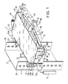
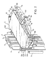
- the unitary module illustrated in FIGS. 1 to 4 is generally designated by the reference 1. It is mounted horizontally either on a truss 2 formed by a U-shaped rail or on a truss 3 constituted by a linear rail, as shown in FIGS. 1 and 2. It can just as easily be mounted vertically on farm 2 or 3, then horizontal.
- the only module 1 shown and other modules which are identical to it are held individually by forming together a stack of modules against each other.
- this module 1 is an optical connection cassette.
- This cassette has a double compartment 11 and 12, defined on either side of a horizontal separation fabric 10, substantially median.
- the lower compartment 11 is assigned to the storage of a length reserve of a cable conductor 13A 13.
- the upper compartment 12 is assigned to the storage of a length reserve of a jumper conductor 14 to be connected to the conductor 13A.
- This cassette 1 receives a support element 15 for a connector 16, on its front face. It has on its rear face the mounting and fixing device 17 on the farm 2 in a U, or on the farm 3 of straight profile. It further comprises laterally two rings 18 for the passage of the garters serving a stack of cassettes, with an opening 18A on the front of each ring for the output of the garter for the cassette concerned.
- a location 19 for attaching an optical connector 20 is also provided on the underside of the fabric 10, in the lower compartment 11.
- This optical connector 20 connects the conductor 13A of the cable 13 to the jumper conductor 14, in l absence of connector 16 mounted on its front face, or preferably to an optical cord 21 coiled with this conductor 13 in the compartment 11.
- the cord 21 is moreover connected on the front face of the cassette to the jumper 14 by the connector before 16.
- the connector 16 is formed by two half-connectors 16A, 16B, for example complementary and pluggable into one another, initially mounted on their ends to be connected to one another. be cord 21 and jumper 14, for easy and quick connection to the operating site. It constitutes a removable connection known as patching of connections.
- optical connection 20 is made on site just before the cassette is placed in its stack. This optical connection constitutes a fixed and final connection, not giving rise to any subsequent modification, except in exceptional cases.
- a cover 25 is attached and fixed for example by clip on the upper face of the upper compartment 12.
- the lower compartment 11 has its lower face left open.
- the cassette is 24 mm high.
- the mounting and fixing device 17 is formed by two vertical sets of three latching lugs 17A, B, C. It allows the mounting of the cassette on the farm 2 in U whose branches 2A are notched 4, in step 16 mm between them, or on the truss 3, the straight profile of which has two lateral fins 5 and ribbed middle part 6.
- the individual cassettes are alternately retained by their two terminal latching lugs 17A, 17C, for one of the cassettes, and by their central latching latch 17B, for the adjacent cassette, which are engaged in the corresponding notches of each branch 2A of the U-shaped profile.
- the cable can just as easily arrive laterally or through the interior of the U at the rear of the stack of cassettes, as illustrated by the cable 13 or another cable 13 '.
- the cover 25 of the upper compartment 12 has two rear protuberances 25A extending substantially on either side of the two sets of lugs of the device 17, while being substantially level with the upper lug 17A.
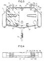
- This device 17 is specified with reference to FIGS. 3 and 4.
- the latching lugs 17A to C also have a significant protrusion 49 on the outer face of each of them, forming an actuating lever of the elastic latching lug which carries it.
- This lever 49 is used for the installation of the cassette on the farm, but especially for the release of the terminal teeth from the notches of the farm 2 and the extraction of the cassette.
- the protuberance 25A left at each end of the rear edge of the cover 25 comes laterally substantially just above the upper latching tab 17A of each set. It allows the operator to blindly position his finger on the levers only. actuation of the latching tabs of the cassette concerned, for their release.
Abstract
Description
La présente invention porte sur un dispositif de montage et de fixation de modules unitaires sur un support de maintien de type rail linéaire ou rail en U.The present invention relates to a device for mounting and fixing unit modules on a linear rail or U-shaped support.
De manière courante, le dispositif de montage et de fixation de modules unitaires sur un rail est constitué par une paire de pattes élastiques d'encliquetage prévues sur une face dite arrière de fixation de chacun des modules. Cette paire de pattes est adaptée au type de rail recevant les modules, pour venir s'encliqueter sur les bords du rail linéaire ou dans des encoches des branches du rail en U.Commonly, the device for mounting and fixing unit modules on a rail is constituted by a pair of elastic snap tabs provided on a so-called rear face for fixing each of the modules. This pair of legs is suitable for the type of rail receiving the modules, to snap onto the edges of the linear rail or in notches in the branches of the U-shaped rail.
La présente invention a pour but de permettre le montage et la fixation de modules unitaires aussi bien sur un rail linéaire ou que sur un rail en U.The object of the present invention is to allow the mounting and fixing of unit modules both on a linear rail or on a U-shaped rail.
Selon la présente invention, le dispositif de montage et de fixation de modules unitaires sur un support de maintien de type rail, comportant au moins une paire de pattes élastiques d'encliquetage saillantes en regard l'une de l'autre sur une face dite arrière de fixation de chacun desdits modules, est caractérisé en ce lesdites pattes élastiques d'encliquetage forment entre elles deux jeux de pattes individuelles d'encliquetage, sont chacune à dent intérieure terminale tournée vers la patte d'encliquetage de même niveau de l'autre jeu et ont entre elles un pas sous multiple du pas entre des encoches sur ledit support de maintien d'un premier type et formé par un rail en U et en ce qu'il comporte, en outre deux pattes rigides intérieures saillantes sur ladite face arrière entre lesdits deux jeux de pattes d'encliquetage, sur leur hauteur, et associées à l'un et l'autre des ces deux jeux respectivement pour le montage possible dudit module sur ledit support de maintien d'un deuxième type et formé par un rail rectiligne.According to the present invention, the device for mounting and fixing unit modules on a rail-type support, comprising at least one pair of resilient snap-on lugs projecting opposite one another on a so-called rear face for fixing each of said modules, is characterized in that said elastic snap-on tabs form between them two sets of individual snap-on tabs, are each with an internal end tooth facing the snap-on tab of the same level of the other set and have between them a pitch under multiple of the pitch between notches on said retaining support of a first type and formed by a U-shaped rail and in that it further comprises two rigid internal legs projecting from said rear face between said two sets of latching tabs, on their height, and associated with one and the other of these two sets respectively for the possible mounting of said module on said support for holding a second type and formed by a straight rail.
Selon une caractéristique additionnelle dudit dispositif, lesdites pattes d'encliquetage comportent en outre chacune une excroissance extérieure dite levier d'actionnement de la patte d'encliquetage qui la porte.According to an additional characteristic of said device, said latching tabs each further comprise an external protrusion said actuation lever of the latching tab which carries it.
Avantageusement ledit dispositif comporte, en outre, deux excroissances supplémentaires, s'étendant saillantes sur ladite face arrière de fixation sur l'extérieur des deux jeux de pattes d'encliquetage, respectivement, et sensiblement en regard de l'une des pattes d'encliquetage terminales de chaque jeu, constituant un moyen de guidage en aveugle d'actionnement au doigt des seules pattes d'encliquetage de ce module, pour l'opérateur, pour l'extraction de ce seul module d'un empilement de modules sur ledit support de maintien.Advantageously, said device comprises, in addition, two additional protuberances, projecting from said rear face for fixing on the outside of the two sets of latching lugs, respectively, and substantially facing one of the latching lugs. terminals of each set, constituting a blind guide means for finger actuation of the latching tabs of this module, for the operator, for the extraction of this single module from a stack of modules on said support maintenance.
Les caractéristiques et avantages de la présente invention apparaîtront clairement au cours de la description détaillée faite ci-après d'un mode préféré de réalisation donné à titre d'exemple et illustré dans les dessins ci-annexés. Dans ces dessins :
- - la figure 1 et la figure 2 sont deux vues schématiques en perspective montrant un module unitaire maintenu sur un rail en U et un rail linéaire, conformément à la présente invention,
- - la figure 3 est une vue de dessus de ce module unitaire, et
- - la figure 4 est une vue de sa face arrière équipée du dispositif de montage et de fixation de ce module.
- FIG. 1 and FIG. 2 are two schematic perspective views showing a unitary module held on a U-shaped rail and a linear rail, in accordance with the present invention,
- FIG. 3 is a top view of this unit module, and
- - Figure 4 is a view of its rear face equipped with the device for mounting and fixing this module.
Le module unitaire illustré dans les figures 1 à 4 est désigné globalement par la référence 1. Il est monté horizontalement indifféremment sur une ferme 2 constituée par un rail en U ou sur une ferme 3 constitué par un rail linéaire, comme représenté dans les figures 1 et 2. Il peut tout aussi bien être monté verticalement sur la ferme 2 ou 3 alors horizontale.The unitary module illustrated in FIGS. 1 to 4 is generally designated by the
Sur l'une ou l'autre des fermes 2 et 3, le seul module 1 représenté et d'autres modules qui lui sont identiques sont maintenus individuellement en formant ensemble un empilement de modules les uns contre les autres.On one or other of the farms 2 and 3, the
Dans l'exemple illustré, ce module 1 est une cassette de raccordement optique. Cette cassette est à double compartiment 11 et 12, définis de part et d'autre d'une toile horizontale de séparation 10, sensiblement médiane. Le compartiment inférieur 11 est affecté au stockage d'une réserve de longueur d'un conducteur 13A de câble 13. Le compartiment supérieur 12 est affecté au stockage d'une réserve de longueur d'un conducteur jarretière 14 à raccorder au conducteur 13A.In the example illustrated, this
Cette cassette 1 reçoit un élément support 15 pour un connecteur 16, sur sa face avant. Elle comporte sur sa face arrière le dispositif de montage et de fixation 17 sur la ferme 2 en U, ou sur la ferme 3 de profilé rectiligne. Elle comporte en outre latéralement deux anneaux 18 de passage des jarretières desservant un empilement de cassettes, avec une ouverture 18A sur l'avant de chaque anneau pour la sortie de la jarretière pour la cassette concernée.This
Un emplacement 19 d'accrochage d'un raccord optique 20 est en outre prévu sur la face inférieure de la toile 10, dans le compartiment inférieur 11. Ce raccord optique 20 relie le conducteur 13A du câble 13 au conducteur de jarretière 14, en l'absence de connecteur 16 monté sur sa face avant, ou de préférence à un cordon optique 21 lové avec ce conducteur 13 dans le compartiment 11. Le cordon 21 est par ailleurs raccordé sur la face avant de la cassette à la jarretière 14 par le connecteur avant 16.A
Le connecteur 16 est formé de deux demi- connecteurs 16A, 16B par exemple complémentaires et enfichables l'un dans l'autre, montés initialement sur leurs extrémités à raccorder l'une à l'autre du cordon 21 et de la jarretière 14, pour leur raccordement aisé et rapide sur le site d'exploitation. Il constitue une connexion démontable dite de brassage des raccordements.The
Le raccord optique 20 est quant à lui réalisé sur site juste avant la mise en place de la cassette dans son empilement. Ce raccord optique constitue une connexion fixe et définitive, ne donnant lieu à aucune modification ultérieure, sauf cas exceptionnel.The
Un couvercle 25 est rapporté et fixé par exemple par clip sur la face supérieure du compartiment supérieur 12. Le compartiment inférieur 11 a sa face inférieure laissée ouverte.A
Un rebord périphérique 30 saillant sur l'une et l'autre des deux faces de la toile 10, à l'exception du bord avant de sa face supérieure, délimite latéralement les deux compartiments 11 et 12, ferme la face avant 31 du compartiment inférieur mais laisse ouverte toute la face avant 32 du compartiment supérieur 12. Seul l'élément 15 support du connecteur 16 vient faire obstacle dans la face avant du compartiment 12, quand il est en place, et retient la surlongueur de jarretière stockée dans ce compartiment 12.A
Dans cette réalisation, la cassette est de 24 mm de hauteur.In this embodiment, the cassette is 24 mm high.
Le dispositif de montage et de fixation 17 est formé par deux jeux verticaux de trois pattes d'encliquetage 17A, B, C. Il permet le montage de la cassette sur la ferme 2 en U dont les branches 2A sont à encoches 4, au pas de 16 mm entre elles, ou sur la ferme 3 dont le profilé rectiligne est à deux ailettes latérales 5 et partie médiane nervurée 6.The mounting and
Ainsi, dans un empilement de cassettes sur la ferme 2 en U, les cassettes individuelles sont alternativement retenues par leurs deux pattes terminales d'encliquetage 17A, 17C, pour l'une des cassettes, et par leur patte médiane d'encliquetage 17B, pour la cassette adjacente, qui sont engagées dans les encoches correspondantes de chaque branche 2A du profilé en U.Thus, in a stack of cassettes on the U-shaped farm 2, the individual cassettes are alternately retained by their two
Avec cette ferme 2 en U, le câble peut tout aussi bien arriver latéralement ou par l'intérieur du U à l'arrière de l'empilement de cassettes, comme illustré par le câble 13 ou un autre câble 13'.With this U-shaped farm 2, the cable can just as easily arrive laterally or through the interior of the U at the rear of the stack of cassettes, as illustrated by the
Dans un empilement de cassettes sur la ferme 3, les cassettes successives sont retenues par leurs deux jeux de pattes sur les bords des ailettes latérales 5 du profilé rectiligne.In a stack of cassettes on the farm 3, the successive cassettes are retained by their two sets of tabs on the edges of the
Avantageusement, le couvercle 25 du compartiment supérieur 12 présente deux excroissances arrière 25A s'étendant sensiblement de part et d'autre des deux jeux de pattes du dispositif 17, en étant sensiblement à niveau avec la patte supérieure 17A.Advantageously, the
Ce dispositif 17 est précisé en regard des figures 3 et 4.This
Il est formé par les deux jeux de trois pattes élastiques d'encliquetage présentant chacune une dent terminale 47 saillante sur leur face intérieure tournée vers le plan de symétrie de la cassette. Il comporte en outre une patte intérieure rigide 48, de butée, associée à chaque jeu de pattes 17A, 17B, 17C, continue sur la hauteur du jeu et légèrement écartée de lui. Le bord arrière de cette patte de butée en retrait sur les dents terminales 47 et est chanfreiné en regard des dents terminales.It is formed by the two sets of three elastic latching tabs each having a terminal tooth 47 projecting from their inner face facing the plane of symmetry of the cassette. It further comprises a rigid
Cet agencement permet la retenue de la cassette sur la ferme 2, dont les branches du U s'insèrent entre le jeu de pattes d'encliquetage et la patte de butée jusqu'à que les dents terminales 47 rentrent dans les encoches 4 correspondantes. Il permet aussi la retenue de cette cassette sur la ferme 3 dont les bords des ailettes 5 s'insèrent entre les dents terminales et le bord arrière de la patte de butée 48.This arrangement allows the cassette to be retained on the farm 2, the branches of the U of which are inserted between the set of latching tabs and the stop tab until the terminal teeth 47 fit into the
Les pattes d'encliquetage 17A à C présentent en outre une excroissance importante 49 sur la face extérieure de chacune d'elles, formant levier d'actionnement de la patte élastique d'encliquetage qui la porte. Ce levier 49 est utilisé pour la mise en place de la cassette sur la ferme, mais surtout pour le dégagement des dents terminales des encoches de la ferme 2 et l'extraction de la cassette.The
L'excroissance 25A laissée à chaque extrémité du bord arrière du couvercle 25 vient latéralement sensiblement juste au dessus de la patte supérieure d'encliquetage 17A de chaque jeu. Elle permet à l'opérateur de venir positionner en aveugle son doigt sur les seuls leviers d'actionnement des pattes d'encliquetage de la cassette concernée, pour leur désencliquetage.The
Claims (3)
Applications Claiming Priority (2)
| Application Number | Priority Date | Filing Date | Title |
|---|---|---|---|
| FR9012244 | 1990-10-04 | ||
| FR9012244 | 1990-10-04 |
Publications (2)
| Publication Number | Publication Date |
|---|---|
| EP0479227A1 true EP0479227A1 (en) | 1992-04-08 |
| EP0479227B1 EP0479227B1 (en) | 1996-05-22 |
Family
ID=9400938
Family Applications (2)
| Application Number | Title | Priority Date | Filing Date |
|---|---|---|---|
| EP91116753A Expired - Lifetime EP0479227B1 (en) | 1990-10-04 | 1991-10-01 | Device for fixing and mounting unitary modules on a supporting frame |
| EP91116752A Expired - Lifetime EP0479226B1 (en) | 1990-10-04 | 1991-10-01 | Cassette for optical junction |
Family Applications After (1)
| Application Number | Title | Priority Date | Filing Date |
|---|---|---|---|
| EP91116752A Expired - Lifetime EP0479226B1 (en) | 1990-10-04 | 1991-10-01 | Cassette for optical junction |
Country Status (5)
| Country | Link |
|---|---|
| US (1) | US5430823A (en) |
| EP (2) | EP0479227B1 (en) |
| JP (1) | JP2801100B2 (en) |
| DE (2) | DE69124902T2 (en) |
| ES (2) | ES2100189T3 (en) |
Cited By (6)
| Publication number | Priority date | Publication date | Assignee | Title |
|---|---|---|---|---|
| US5363465A (en) * | 1993-02-19 | 1994-11-08 | Adc Telecommunications, Inc. | Fiber optic connector module |
| WO2000065397A1 (en) * | 1999-04-21 | 2000-11-02 | Tyco Electonics Raychem Nv | Optical fibre organiser |
| WO2007051611A2 (en) * | 2005-11-07 | 2007-05-10 | Adc Gmbh | Method and device for coupling optical waveguides |
| NL2001966C (en) * | 2008-09-09 | 2010-03-15 | Attema Kunststoffenind | A holder for multiple optical fibre connections. |
| EP2163926A1 (en) * | 2008-09-09 | 2010-03-17 | B.V. Kunststoffenindustrie Attema | A holding system provided with a cassette comprising a holder for holding optical fibre connections |
| WO2012059448A1 (en) * | 2010-11-05 | 2012-05-10 | Tyco Electronics Raychem Bvba | Optical fibre coupling device and optical fibre coupling assembly |
Families Citing this family (76)
| Publication number | Priority date | Publication date | Assignee | Title |
|---|---|---|---|---|
| ATE165451T1 (en) * | 1993-05-17 | 1998-05-15 | Cla Son Leasing Und Holding Gm | DISTRIBUTION CABINET |
| JPH0716902U (en) * | 1993-08-25 | 1995-03-20 | 株式会社昭電 | Photo termination box |
| TW232757B (en) * | 1994-01-21 | 1994-10-21 | Adc Telecommunications Inc | High-density fiber distribution frame |
| US5559922A (en) * | 1995-02-28 | 1996-09-24 | Lucent Technologies Inc. | Wire guide and optical fiber storage spool assembly |
| US5640482A (en) * | 1995-08-31 | 1997-06-17 | The Whitaker Corporation | Fiber optic cable management rack |
| US5758003A (en) * | 1996-03-15 | 1998-05-26 | Adc Telecommunications, Inc. | High density fiber management |
| FR2756382B1 (en) * | 1996-11-25 | 1998-12-24 | Proptic | CABLE CONNECTION DEVICE |
| US5946440A (en) * | 1997-11-17 | 1999-08-31 | Adc Telecommunications, Inc. | Optical fiber cable management device |
| US6088503A (en) * | 1998-02-02 | 2000-07-11 | Ciena Corporation | Optical fiber precision handling tool |
| US6201919B1 (en) * | 1998-12-16 | 2001-03-13 | Adc Telecommunications, Inc | Fiber distribution frame |
| US6278829B1 (en) * | 1999-05-05 | 2001-08-21 | Marconi Communications, Inc. | Optical fiber routing and support apparatus |
| GB2354338A (en) * | 1999-08-03 | 2001-03-21 | Raychem Sa Nv | Fibre optic splice shelf with cable storage below |
| DE10040651B4 (en) * | 2000-08-19 | 2004-02-05 | Erni Elektroapparate Gmbh | Electronic device with data and / or power bus connection |
| US6360050B1 (en) | 2000-09-08 | 2002-03-19 | Telect, Inc. | High density fiber distribution tray system |
| US6633717B1 (en) | 2000-09-08 | 2003-10-14 | Telect, Inc. | High density fiber optic cable distribution frame system |
| GB2373341A (en) * | 2001-03-15 | 2002-09-18 | Tyco Electronics Raychem Nv | Cable attachment device having plates and mounting means |
| US6522824B2 (en) * | 2001-03-26 | 2003-02-18 | Corning Cable Systems Llc | Corner wall-mount fiber optic connector housing |
| US6944387B2 (en) | 2001-04-30 | 2005-09-13 | Telect, Inc. | Fiber optic connector tray system |
| US6674952B2 (en) | 2001-04-30 | 2004-01-06 | Telect, Inc. | Fiber optic cable bend radius protection system |
| US6819857B2 (en) | 2001-10-12 | 2004-11-16 | Adc Telecommunications, Inc. | Rotating vertical fiber tray and methods |
| US6591051B2 (en) | 2001-11-16 | 2003-07-08 | Adc Telecommunications, Inc. | Fiber termination block with angled slide |
| US6711338B2 (en) * | 2002-02-27 | 2004-03-23 | Lucent Technologies Inc. | Jumper cable module |
| JP4532388B2 (en) * | 2005-10-18 | 2010-08-25 | ホーチキ株式会社 | Communication cable housing structure |
| US20080047502A1 (en) * | 2006-08-23 | 2008-02-28 | Michael Russo | Hybrid Cycle Electrolysis Power System with Hydrogen & Oxygen Energy Storage |
| US7474828B2 (en) | 2006-10-02 | 2009-01-06 | Emerson Network Power, Energy Systems, North America, Inc. | Slack limiting fiber management system for an optic fiber distribution hub |
| US20080080825A1 (en) * | 2006-10-02 | 2008-04-03 | Eduardo Leon | Optic fiber distribution hub |
| US7428363B2 (en) * | 2006-10-02 | 2008-09-23 | Emerson Network Power, Energy Systems, North America, Inc. | Distribution module for an optic fiber distribution hub |
| US7526174B2 (en) * | 2006-10-02 | 2009-04-28 | Emerson Network Power, Energy Systems, North America, Inc. | Universal splitter module holder for an optic fiber distribution hub |
| DE102007010863B4 (en) * | 2007-03-01 | 2009-01-08 | Adc Gmbh | Sleeve for fiber optic cable |
| DE102007032186A1 (en) * | 2007-03-01 | 2008-12-18 | Adc Gmbh | Support system for fastening fiber optic telecommunications and data equipment, includes profile terminated by specially-shaped U- and V-sections at its ends |
| DE102007010855B4 (en) * | 2007-03-01 | 2009-01-08 | Adc Gmbh | Support system for a distributor device for optical waveguides |
| DE102007010853B4 (en) | 2007-03-01 | 2009-01-29 | Adc Gmbh | Distributor device for optical waveguides |
| US8417074B2 (en) | 2008-11-21 | 2013-04-09 | Adc Telecommunications, Inc. | Fiber optic telecommunications module |
| US8958679B2 (en) | 2010-03-02 | 2015-02-17 | Tyco Electronics Services Gmbh | Fibre-optic telecommunications module |
| CN101923197A (en) * | 2010-08-04 | 2010-12-22 | 南京华脉科技有限公司 | Main distribution frame for fiber |
| US9014527B2 (en) | 2011-04-25 | 2015-04-21 | Adc Telecommunication, Inc. | Rack and chassis for fiber optic sliding adapter modules |
| US9229172B2 (en) | 2011-09-12 | 2016-01-05 | Commscope Technologies Llc | Bend-limited flexible optical interconnect device for signal distribution |
| US9417418B2 (en) | 2011-09-12 | 2016-08-16 | Commscope Technologies Llc | Flexible lensed optical interconnect device for signal distribution |
| US8770861B2 (en) | 2011-09-27 | 2014-07-08 | Tyco Electronics Corporation | Outside plant termination enclosure |
| CN105068204B (en) | 2011-10-07 | 2018-08-10 | Adc电信公司 | Slidably optical link module with cable slack management |
| US9002166B2 (en) | 2011-10-07 | 2015-04-07 | Adc Telecommunications, Inc. | Slidable fiber optic connection module with cable slack management |
| CN108594384B (en) | 2011-10-07 | 2022-03-08 | Adc电信公司 | Fiber optic cassettes, systems and methods |
| US9170391B2 (en) | 2011-10-07 | 2015-10-27 | Adc Telecommunications, Inc. | Slidable fiber optic connection module with cable slack management |
| US9075203B2 (en) | 2012-01-17 | 2015-07-07 | Adc Telecommunications, Inc. | Fiber optic adapter block |
| US9195021B2 (en) | 2012-09-21 | 2015-11-24 | Adc Telecommunications, Inc. | Slidable fiber optic connection module with cable slack management |
| US10082636B2 (en) | 2012-09-21 | 2018-09-25 | Commscope Technologies Llc | Slidable fiber optic connection module with cable slack management |
| RU2654358C2 (en) | 2012-09-28 | 2018-05-17 | Тайко Электроникс Юк Лтд. | Fiber optic cassette |
| US9146374B2 (en) | 2012-09-28 | 2015-09-29 | Adc Telecommunications, Inc. | Rapid deployment packaging for optical fiber |
| AU2013323664B2 (en) | 2012-09-28 | 2017-12-07 | Adc Telecommunications, Inc. | Manufacture and testing of fiber optic cassette |
| US9223094B2 (en) | 2012-10-05 | 2015-12-29 | Tyco Electronics Nederland Bv | Flexible optical circuit, cassettes, and methods |
| EP2951633B1 (en) | 2013-01-29 | 2020-05-20 | CommScope Connectivity Belgium BVBA | Optical fiber distribution system |
| US9128262B2 (en) | 2013-02-05 | 2015-09-08 | Adc Telecommunications, Inc. | Slidable telecommunications tray with cable slack management |
| WO2014133943A1 (en) | 2013-02-27 | 2014-09-04 | Adc Telecommunications, Inc. | Slidable fiber optic connection module with cable slack management |
| US9435975B2 (en) | 2013-03-15 | 2016-09-06 | Commscope Technologies Llc | Modular high density telecommunications frame and chassis system |
| AU2014257660B2 (en) | 2013-04-24 | 2018-03-22 | CommScope Connectivity Belgium BVBA | Universal mounting mechanism for mounting a telecommunications chassis to a telecommunications fixture |
| AP2015008820A0 (en) | 2013-04-24 | 2015-10-31 | Adc Czech Republic Sro | Optical fiber distribution system |
| US9851524B2 (en) | 2014-01-28 | 2017-12-26 | Commscope Technologies Llc | Slidable fiber optic connection module with cable slack management |
| US9494758B2 (en) | 2014-04-03 | 2016-11-15 | Commscope Technologies Llc | Fiber optic distribution system |
| EP3230780B1 (en) | 2014-12-10 | 2023-10-25 | CommScope Technologies LLC | Fiber optic cable slack management module |
| WO2016156611A1 (en) | 2015-04-03 | 2016-10-06 | CommScope Connectivity Belgium BVBA | Telecommunications distribution elements |
| EP3446554B1 (en) | 2016-04-19 | 2020-12-02 | CommScope, Inc. of North Carolina | Telecommunications chassis with slidable trays |
| WO2017184501A1 (en) | 2016-04-19 | 2017-10-26 | Commscope, Inc. Of North Carolina | Door assembly for a telecommunications chassis with a combination hinge structure |
| WO2018046677A1 (en) | 2016-09-08 | 2018-03-15 | CommScope Connectivity Belgium BVBA | Telecommunications distribution elements |
| WO2018226959A1 (en) | 2017-06-07 | 2018-12-13 | Commscope Technologies Llc | Fiber optic adapter and cassette |
| CN107065109B (en) * | 2017-06-22 | 2019-06-28 | 国家电网公司 | A kind of plastic box type optical splitter installation module |
| WO2019070682A2 (en) | 2017-10-02 | 2019-04-11 | Commscope Technologies Llc | Fiber optic circuit and preparation method |
| US11385429B2 (en) | 2017-10-18 | 2022-07-12 | Commscope Technologies Llc | Fiber optic connection cassette |
| US11852882B2 (en) | 2018-02-28 | 2023-12-26 | Commscope Technologies Llc | Packaging assembly for telecommunications equipment |
| WO2019204317A1 (en) | 2018-04-16 | 2019-10-24 | Commscope Technologies Llc | Adapter structure |
| EP3781973A1 (en) | 2018-04-17 | 2021-02-24 | CommScope Connectivity Belgium BVBA | Telecommunications distribution elements |
| EP3844973A1 (en) | 2018-08-31 | 2021-07-07 | CommScope Connectivity Belgium BVBA | Frame assemblies for optical fiber distribution elements |
| EP3844972B1 (en) | 2018-08-31 | 2022-08-03 | CommScope Connectivity Belgium BVBA | Frame assemblies for optical fiber distribution elements |
| WO2020043909A1 (en) | 2018-08-31 | 2020-03-05 | CommScope Connectivity Belgium BVBA | Frame assemblies for optical fiber distribution elements |
| EP3845044B1 (en) | 2018-08-31 | 2023-02-15 | CommScope Connectivity Belgium BVBA | Frame assemblies for optical fiber distribution elements |
| US11947177B2 (en) | 2019-01-25 | 2024-04-02 | CommScope Connectivity Belgium BVBA | Frame assemblies for optical fiber distribution elements |
| WO2023140287A1 (en) * | 2022-01-21 | 2023-07-27 | 住友電工オプティフロンティア株式会社 | Package for optical fiber, packaged article, and optical fiber lead-out method |
Citations (1)
| Publication number | Priority date | Publication date | Assignee | Title |
|---|---|---|---|---|
| EP0208155A1 (en) * | 1985-06-12 | 1987-01-14 | Entrelec Sa | Connection block for optical fibres |
Family Cites Families (18)
| Publication number | Priority date | Publication date | Assignee | Title |
|---|---|---|---|---|
| JPS59102208A (en) * | 1982-12-06 | 1984-06-13 | Nippon Telegr & Teleph Corp <Ntt> | Containing structure of optical fiber core wire connecting part |
| JPS6155607A (en) * | 1984-08-28 | 1986-03-20 | Fujitsu Ltd | Light distributing board |
| JPS6183504A (en) * | 1984-10-01 | 1986-04-28 | Nec Corp | Connecting box for optical fiber cable |
| CA1249741A (en) * | 1984-10-25 | 1989-02-07 | Michael J. Donaldson | Optical cable terminating equipment |
| FR2590371B1 (en) * | 1985-11-18 | 1988-09-16 | Cit Alcatel | OPTICAL CABLES HEAD CHASSIS |
| JPS6365004U (en) * | 1986-10-18 | 1988-04-28 | ||
| JPS63135306U (en) * | 1987-02-27 | 1988-09-06 | ||
| DE3706768A1 (en) * | 1987-03-03 | 1988-09-15 | Philips Patentverwaltung | RECEIVING DEVICE FOR THE STOCK LENGTH OF AT LEAST ONE LIGHT WAVE GUIDE |
| CH674110A5 (en) * | 1987-04-28 | 1990-04-30 | Reichle & De Massari Fa | |
| DE3838428A1 (en) * | 1988-11-12 | 1990-05-31 | Philips Patentverwaltung | SWITCH DISTRIBUTOR FOR THE PRODUCTION OF FREELY SELECTABLE OPTICAL CONNECTORS |
| US5071211A (en) * | 1988-12-20 | 1991-12-10 | Northern Telecom Limited | Connector holders and distribution frame and connector holder assemblies for optical cable |
| US4971421A (en) * | 1989-09-29 | 1990-11-20 | Reliance Comm/Tec Corporation | Fiber optic splice and patch enclosure |
| US5142607A (en) * | 1990-03-20 | 1992-08-25 | Rittal-Werk Rudolf Loh Gmbh & Co. Kg | Splice box for optical wave guide |
| US5187766A (en) * | 1991-02-27 | 1993-02-16 | Siemens Aktiengesellschaft | Optical fiber waveguide division rack for holding plural cassettes |
| FR2687743B1 (en) * | 1992-02-21 | 1995-06-16 | Mars Actel | SET OF STACKED AND ARTICULATED MODULES. |
| FR2687801B1 (en) * | 1992-02-21 | 1997-01-03 | Mars Actel | OPTICAL FIBER CASSETTE. |
| FR2687800B1 (en) * | 1992-02-21 | 1994-04-08 | Mars Actel | ADAPTABLE CASSETTE FOR LOVING AND SPLICING OPTICAL FIBERS. |
| US5353367A (en) * | 1993-11-29 | 1994-10-04 | Northern Telecom Limited | Distribution frame and optical connector holder combination |
-
1991
- 1991-10-01 EP EP91116753A patent/EP0479227B1/en not_active Expired - Lifetime
- 1991-10-01 DE DE69124902T patent/DE69124902T2/en not_active Expired - Fee Related
- 1991-10-01 ES ES91116752T patent/ES2100189T3/en not_active Expired - Lifetime
- 1991-10-01 DE DE69119684T patent/DE69119684T2/en not_active Expired - Fee Related
- 1991-10-01 ES ES91116753T patent/ES2087198T3/en not_active Expired - Lifetime
- 1991-10-01 EP EP91116752A patent/EP0479226B1/en not_active Expired - Lifetime
- 1991-10-04 JP JP3323630A patent/JP2801100B2/en not_active Expired - Fee Related
- 1991-10-04 US US07/771,103 patent/US5430823A/en not_active Expired - Lifetime
Patent Citations (1)
| Publication number | Priority date | Publication date | Assignee | Title |
|---|---|---|---|---|
| EP0208155A1 (en) * | 1985-06-12 | 1987-01-14 | Entrelec Sa | Connection block for optical fibres |
Cited By (8)
| Publication number | Priority date | Publication date | Assignee | Title |
|---|---|---|---|---|
| US5363465A (en) * | 1993-02-19 | 1994-11-08 | Adc Telecommunications, Inc. | Fiber optic connector module |
| WO2000065397A1 (en) * | 1999-04-21 | 2000-11-02 | Tyco Electonics Raychem Nv | Optical fibre organiser |
| WO2007051611A2 (en) * | 2005-11-07 | 2007-05-10 | Adc Gmbh | Method and device for coupling optical waveguides |
| WO2007051611A3 (en) * | 2005-11-07 | 2007-08-23 | Adc Gmbh | Method and device for coupling optical waveguides |
| US8019191B2 (en) | 2005-11-07 | 2011-09-13 | Adc Gmbh | Method and device for coupling optical waveguides |
| NL2001966C (en) * | 2008-09-09 | 2010-03-15 | Attema Kunststoffenind | A holder for multiple optical fibre connections. |
| EP2163926A1 (en) * | 2008-09-09 | 2010-03-17 | B.V. Kunststoffenindustrie Attema | A holding system provided with a cassette comprising a holder for holding optical fibre connections |
| WO2012059448A1 (en) * | 2010-11-05 | 2012-05-10 | Tyco Electronics Raychem Bvba | Optical fibre coupling device and optical fibre coupling assembly |
Also Published As
| Publication number | Publication date |
|---|---|
| JP2801100B2 (en) | 1998-09-21 |
| DE69124902D1 (en) | 1997-04-10 |
| ES2087198T3 (en) | 1996-07-16 |
| EP0479226B1 (en) | 1997-03-05 |
| DE69124902T2 (en) | 1997-06-19 |
| US5430823A (en) | 1995-07-04 |
| DE69119684T2 (en) | 1996-10-02 |
| JPH05203814A (en) | 1993-08-13 |
| DE69119684D1 (en) | 1996-06-27 |
| EP0479227B1 (en) | 1996-05-22 |
| EP0479226A1 (en) | 1992-04-08 |
| ES2100189T3 (en) | 1997-06-16 |
Similar Documents
| Publication | Publication Date | Title |
|---|---|---|
| EP0479227B1 (en) | Device for fixing and mounting unitary modules on a supporting frame | |
| EP0822364B1 (en) | Coupling for cableway sections and cableway sections obtained therefrom | |
| EP0382597B1 (en) | Extruded section, such as a gutter, plinth, trunking or the like, for accommodation and protection, in particular of electrical devices and supply leads | |
| EP0557187B1 (en) | Assembly of flat articulated modules | |
| FR2687743A1 (en) | SET OF STACKED AND ARTICULATED MODULES. | |
| FR2736138A1 (en) | DEVICE FOR FIXING HORIZONTAL CONSOLES ON A VERTICAL MOUNT WITH RACK | |
| WO2006097600A1 (en) | Splice plate for a wire cable tray | |
| EP0226805A1 (en) | Distributor arrangement for fibre-optic cable ends | |
| FR2852157A1 (en) | Fixation device for fixing wire on carrier unit, has wings with end in form of T that has arm adapted to support on face of carrier unit opposed to plain surface at edge of opening | |
| EP2808964A1 (en) | System for providing a horizontal mounting for an object such as a cable trough and rail for such a system | |
| FR2785340A1 (en) | DEVICE FOR FIXING A WIRE ON A CARRIER ELEMENT PROVIDED WITH AT LEAST ONE OPENING AND CARRIER ASSEMBLY FOR A CABLE ROUTE COMPRISING AT LEAST ONE SUCH DEVICE | |
| EP2915936A2 (en) | Connection between a fence and a post | |
| EP1249908B1 (en) | Electrical connector mounting assembly | |
| EP0191667A1 (en) | Cableway of wire mesh | |
| FR2666478A1 (en) | MOUNTING BOX WITH VARIABLE ENTRAX, FOR ELECTRICAL APPARATUS. | |
| EP3555975A1 (en) | System comprising a carrier rail and a plate configured to be attached to a support and to immobilise the rail arranged standing under the support | |
| EP1320163B1 (en) | Locking accessory for a direct snap-on electrical apparatus in a raceway base | |
| EP0725467B1 (en) | Fixation device for assembling metal sheet-cable ducts | |
| EP0751598A1 (en) | Means for attaching a horizontal bracket to a vertical stand by means of a locking key | |
| EP2273636B1 (en) | Accessory for extending a conduit section | |
| EP0917268B1 (en) | Upright for support chassis, in particular for electrical apparatus | |
| EP0646987A1 (en) | Connection assembly having improved reliability | |
| EP0739070B1 (en) | Electrical connecting device for the connection of an electrical apparatus to the network | |
| FR2728401A1 (en) | HOLDING BARRET TO RETAIN CABLES IN A CHUTE | |
| FR2715993A1 (en) | Electrical supply connection unit for public lighting systems |
Legal Events
| Date | Code | Title | Description |
|---|---|---|---|
| PUAI | Public reference made under article 153(3) epc to a published international application that has entered the european phase |
Free format text: ORIGINAL CODE: 0009012 |
|
| AK | Designated contracting states |
Kind code of ref document: A1 Designated state(s): DE ES FR GB IT SE |
|
| 17P | Request for examination filed |
Effective date: 19921006 |
|
| 17Q | First examination report despatched |
Effective date: 19940725 |
|
| RAP1 | Party data changed (applicant data changed or rights of an application transferred) |
Owner name: ALCATEL CABLE INTERFACE |
|
| RAP3 | Party data changed (applicant data changed or rights of an application transferred) |
Owner name: ALCATEL CABLE INTERFACE |
|
| GRAH | Despatch of communication of intention to grant a patent |
Free format text: ORIGINAL CODE: EPIDOS IGRA |
|
| GRAA | (expected) grant |
Free format text: ORIGINAL CODE: 0009210 |
|
| AK | Designated contracting states |
Kind code of ref document: B1 Designated state(s): DE ES FR GB IT SE |
|
| REG | Reference to a national code |
Ref country code: ES Ref legal event code: BA2A Ref document number: 2087198 Country of ref document: ES Kind code of ref document: T3 |
|
| REF | Corresponds to: |
Ref document number: 69119684 Country of ref document: DE Date of ref document: 19960627 |
|
| REG | Reference to a national code |
Ref country code: ES Ref legal event code: FG2A Ref document number: 2087198 Country of ref document: ES Kind code of ref document: T3 |
|
| ITF | It: translation for a ep patent filed |
Owner name: JACOBACCI & PERANI S.P.A. |
|
| GBT | Gb: translation of ep patent filed (gb section 77(6)(a)/1977) |
Effective date: 19960725 |
|
| PLBE | No opposition filed within time limit |
Free format text: ORIGINAL CODE: 0009261 |
|
| STAA | Information on the status of an ep patent application or granted ep patent |
Free format text: STATUS: NO OPPOSITION FILED WITHIN TIME LIMIT |
|
| 26N | No opposition filed | ||
| PGFP | Annual fee paid to national office [announced via postgrant information from national office to epo] |
Ref country code: GB Payment date: 19980914 Year of fee payment: 8 |
|
| PGFP | Annual fee paid to national office [announced via postgrant information from national office to epo] |
Ref country code: FR Payment date: 19980916 Year of fee payment: 8 |
|
| PGFP | Annual fee paid to national office [announced via postgrant information from national office to epo] |
Ref country code: SE Payment date: 19980918 Year of fee payment: 8 |
|
| PGFP | Annual fee paid to national office [announced via postgrant information from national office to epo] |
Ref country code: DE Payment date: 19980922 Year of fee payment: 8 |
|
| PGFP | Annual fee paid to national office [announced via postgrant information from national office to epo] |
Ref country code: ES Payment date: 19981020 Year of fee payment: 8 |
|
| PG25 | Lapsed in a contracting state [announced via postgrant information from national office to epo] |
Ref country code: GB Free format text: LAPSE BECAUSE OF NON-PAYMENT OF DUE FEES Effective date: 19991001 |
|
| PG25 | Lapsed in a contracting state [announced via postgrant information from national office to epo] |
Ref country code: ES Free format text: LAPSE BECAUSE OF NON-PAYMENT OF DUE FEES Effective date: 19991002 |
|
| PG25 | Lapsed in a contracting state [announced via postgrant information from national office to epo] |
Ref country code: SE Free format text: THE PATENT HAS BEEN ANNULLED BY A DECISION OF A NATIONAL AUTHORITY Effective date: 19991030 |
|
| GBPC | Gb: european patent ceased through non-payment of renewal fee |
Effective date: 19991001 |
|
| EUG | Se: european patent has lapsed |
Ref document number: 91116753.4 |
|
| PG25 | Lapsed in a contracting state [announced via postgrant information from national office to epo] |
Ref country code: FR Free format text: LAPSE BECAUSE OF NON-PAYMENT OF DUE FEES Effective date: 20000630 |
|
| PG25 | Lapsed in a contracting state [announced via postgrant information from national office to epo] |
Ref country code: DE Free format text: LAPSE BECAUSE OF NON-PAYMENT OF DUE FEES Effective date: 20000801 |
|
| REG | Reference to a national code |
Ref country code: FR Ref legal event code: ST |
|
| REG | Reference to a national code |
Ref country code: ES Ref legal event code: FD2A Effective date: 20001113 |
|
| PG25 | Lapsed in a contracting state [announced via postgrant information from national office to epo] |
Ref country code: IT Free format text: LAPSE BECAUSE OF NON-PAYMENT OF DUE FEES;WARNING: LAPSES OF ITALIAN PATENTS WITH EFFECTIVE DATE BEFORE 2007 MAY HAVE OCCURRED AT ANY TIME BEFORE 2007. THE CORRECT EFFECTIVE DATE MAY BE DIFFERENT FROM THE ONE RECORDED. Effective date: 20051001 |