EP0481759A2 - Direct access storage device - Google Patents
Direct access storage device Download PDFInfo
- Publication number
- EP0481759A2 EP0481759A2 EP91309534A EP91309534A EP0481759A2 EP 0481759 A2 EP0481759 A2 EP 0481759A2 EP 91309534 A EP91309534 A EP 91309534A EP 91309534 A EP91309534 A EP 91309534A EP 0481759 A2 EP0481759 A2 EP 0481759A2
- Authority
- EP
- European Patent Office
- Prior art keywords
- parity
- data
- block
- blocks
- dasd
- Prior art date
- Legal status (The legal status is an assumption and is not a legal conclusion. Google has not performed a legal analysis and makes no representation as to the accuracy of the status listed.)
- Withdrawn
Links
Images

Classifications
-
- G—PHYSICS
- G06—COMPUTING; CALCULATING OR COUNTING
- G06F—ELECTRIC DIGITAL DATA PROCESSING
- G06F11/00—Error detection; Error correction; Monitoring
- G06F11/07—Responding to the occurrence of a fault, e.g. fault tolerance
- G06F11/08—Error detection or correction by redundancy in data representation, e.g. by using checking codes
- G06F11/10—Adding special bits or symbols to the coded information, e.g. parity check, casting out 9's or 11's
- G06F11/1076—Parity data used in redundant arrays of independent storages, e.g. in RAID systems
-
- G—PHYSICS
- G06—COMPUTING; CALCULATING OR COUNTING
- G06F—ELECTRIC DIGITAL DATA PROCESSING
- G06F11/00—Error detection; Error correction; Monitoring
- G06F11/07—Responding to the occurrence of a fault, e.g. fault tolerance
- G06F11/08—Error detection or correction by redundancy in data representation, e.g. by using checking codes
- G06F11/10—Adding special bits or symbols to the coded information, e.g. parity check, casting out 9's or 11's
- G06F11/1008—Adding special bits or symbols to the coded information, e.g. parity check, casting out 9's or 11's in individual solid state devices
-
- G—PHYSICS
- G06—COMPUTING; CALCULATING OR COUNTING
- G06F—ELECTRIC DIGITAL DATA PROCESSING
- G06F3/00—Input arrangements for transferring data to be processed into a form capable of being handled by the computer; Output arrangements for transferring data from processing unit to output unit, e.g. interface arrangements
- G06F3/06—Digital input from, or digital output to, record carriers, e.g. RAID, emulated record carriers or networked record carriers
- G06F3/0601—Interfaces specially adapted for storage systems
-
- G—PHYSICS
- G11—INFORMATION STORAGE
- G11B—INFORMATION STORAGE BASED ON RELATIVE MOVEMENT BETWEEN RECORD CARRIER AND TRANSDUCER
- G11B20/00—Signal processing not specific to the method of recording or reproducing; Circuits therefor
- G11B20/10—Digital recording or reproducing
- G11B20/18—Error detection or correction; Testing, e.g. of drop-outs
- G11B20/1833—Error detection or correction; Testing, e.g. of drop-outs by adding special lists or symbols to the coded information
-
- G—PHYSICS
- G06—COMPUTING; CALCULATING OR COUNTING
- G06F—ELECTRIC DIGITAL DATA PROCESSING
- G06F3/00—Input arrangements for transferring data to be processed into a form capable of being handled by the computer; Output arrangements for transferring data from processing unit to output unit, e.g. interface arrangements
- G06F3/06—Digital input from, or digital output to, record carriers, e.g. RAID, emulated record carriers or networked record carriers
- G06F3/0601—Interfaces specially adapted for storage systems
- G06F3/0668—Interfaces specially adapted for storage systems adopting a particular infrastructure
- G06F3/0671—In-line storage system
- G06F3/0673—Single storage device
Definitions
- This invention relates to arrays of direct access storage devices (DASDs), and more particularly, to methods and means for reducing the number of track rotations required to write modify a data block and alter the explicit parity of a group of data blocks including any modified block distributed across at least some DASDs.
- DASDs direct access storage devices
- Fast computers include DASD arrays as part of their storage subsystems.
- Array architecture, and organization and distribution of data influence operating performance, fault tolerance and the speed of data rebuild after a fault has occurred.
- the prior art shows that improvements in array performance turn on subtle tuning of array operations.
- a “storage subsystem” attaches a processor or processor array at its I/O boundary over a broadband data and control path.
- the subsystem may consist either of a single cyclic multitrack magnetic information storage device (DASD) individually accessed through its device adapter; several DASDs (denominated a "string") terminating in a common control unit; or an array of DASDs attached by a DASD array controller (DAC).
- DASD cyclic multitrack magnetic information storage device
- DAC DASD array controller
- a "DASD array” is any set of logically related DASDs operable by common mode or means. It includes any set of synchronously selected and operated DASDs. These are used where information is exchanged at a high data rate between fast processors and external storage. Serial to parallel mapping of data blocked at some predetermined size (byte, word, block) sustains the high data rate. The synchronous behavior requires N DASDs to rotate at the same rpm, have the same angular offset, and be simultaneously accessed in an identical manner. This solution while maximizing data transfer rate minimizes concurrency.
- Another type of DASD array comprises a set of DASD related together by the fact that data rendered unavailable through failure of any one DASD can be recovered through the use of redundancy such as parity stored on surviving DASD. Such an array need not necessarily be synchronously operated.
- an "array” is a subscripted variable in which the subscript indexes the relative position order of each instance of the variable; specifically, the position order of each block in the logical track.
- the components of the subscript also define the dimensions of the array.
- array A(i,j) specifies a variable "A" whose relative positions are mapped onto a two dimensional closed integer intervals (1,1 ⁇ (i,j) ⁇ N, K).
- the array dimensions may be mutually exclusive.
- the dimensions represented by the closed integer intervals 1 ⁇ i ⁇ N and 1 ⁇ j ⁇ K could denote an ordering (indexing) of like devices and time respectively, N and K being integer upper bounds.
- column order designates one array dimension and row order designates the other.
- N is the number of DASDs and K is the number of blocks per DASD per track thereof.
- Any physical arrangement of N DASDs synchronously accessed constitutes a DASD array.
- the formatting and subsequent accessing of an array, as a store proceeds. By inserting values in consecutive positions on either a row or a column basis. If the operation is performed in a column direction, it is performed in "column major order”. Likewise, if performed in a row direction, it is performed in "row major order”.
- the first strategy relies upon log based recovery and emphasizes recreating event history. However, it inhibits current processing until completed.
- duplication (sometimes called mirroring) does require significant additional storage resource/cost even though only a small fraction of the data may be rendered unavailable.
- the third strategy using coded data and minimizing additional storage, requires computational resources and a complex storage model.
- the special purpose coded information termed "parity" is stored on the DASD with the data and is redundant.
- "parity” is defined to be any redundancy computationally usable with that portion of available data to recover an unavailable portion. It may include simple parity, Hamming, Reed-Solomon, ECC codes and the like.
- fault tolerance is the number of DASDs which could be made unavailable permitting continued operation of the system.
- Degraded mode designates the continued system operation after a fault.
- Fault is the occurrence of a permanent failure.
- Error is the occurrence of a false value in a data sequence often due to noise or a random or intermittent failure of software or hardware.
- erasure designates the omission of any value in one or more positions in a data sequence.
- Patterson et al. covers duplexing or "mirroring" data on array DASDs and parity encoding.
- the mirroring of data stored on N array DASDs requires at least 2N DADs.
- the combined use of parity encoding of a portion of the data, and an increase in the number of accesses per storage update use less than 2N DASDs.
- Brady et al also discloses the mapping of a sequential file of N*k data and parity blocks, K blocks per track per DASD, onto a two dimensional array (one spatial and one temporal dimension) by synchronously accessing N DASD's through counterpart controllers for the duration of one track revolution.
- Parity coding permits data to be rebuilt using only a portion of the stored data. It saves storage compared to the amount used in duplexing and saves time relative to log based recovery. The performance suffers by an increase in the number of accesses per write update. Ouchi and Clark first taught distributing data and parity blocks from the same logical file over attached DASDs as a fault tolerance and recovery aid.
- the parity block is a XORing (modulo 2 addition) of the binary coded contents of the N-1 other blocks. Contents from any single inaccessible DASD can be recovered by XORing the parity blocks with the blocks stored on the N-2 remaining accessible DASDs. A similar result can be obtained if the parity blocks are not available.
- Patterson's levels 1 and 2 relate to one or more strings of DASD and utilizing data mirroring (data duplexing) and Hamming encoding respectively.
- Patterson's third level is one where read and write operations are synchronously made to N DASD's.
- N-1 DASD's contain data and one DASD contains a parity ranging over the other data DASDs. That is, one check DASD is provided for the group.
- the contents of the failed DASD can be reconstructed in the manner of Ouchi. Parenthetically, he performs a logical record to physical track mapping and accessing onto a DASD array in column major order thereby accommodating both small and large access requests.
- the fourth level improves performance with respect to small read and write accesses. This is achieved by storing blocks along the column extent so that in a first time slot (DASD sector 1) blocks 1 to N can respectively be stored on DASD 1 to N while in the second time slot (DASD sector 2) blocks N+1 to 2N are stored etc. In the Kth time slot (DASD sector K) blocks [(K-1)]*N+1 to KN are stored on corresponding devices.
- Patterson's last and the fifth level distributes data and parity blocks across all array DASDs and encourages small reads and writes attending transaction processing as well- as large reads and writes attending numerically intensive computing.
- RAID levels 3 to 5 may use at least one extra DASD for sparing in the event one of the array DASD faults.
- reference may be made to Dunphy, US-A- 4,914,656, “Disk Drive Memory”, issued April 3, 1990.
- P1 is the modulo 2 addition (XOR) of D1 over DASD1-DASD4.
- P2, P3, and P4 cover D2, D3, and D4 respectively. If DASD1 were to fail its contents could be recreated on a spare DASD, by the XOR of the contents of DASD2-DASD5
- the storage subsystem reserves both the DASDs and a path from the processor to the DASDs during the disk rotation interval between reading the old information and writing the new information.
- the storage subsystem reserves both the DASDs and a path from the processor to the DASDs during the disk rotation interval between reading the old information and writing the new information.
- the present invention provides a method for updating information stored in failure independant form on disks in an array of direct access storage devices connected to a data processing system, said information being stored in the form of data blocks and corresponding parity blocks and at least one of said disks including a reserved portion of storage space, said method comprising the steps of: reading a preselected data block from said disks; writing an updated data block onto said disks; reading an original parity block corresponding to said preselected data block during a former part of a disk revolution; calculating a new parity block corresponding to said updated data block; and writing said new parity block onto said reserved portion of storage space during the latter part of said revolution before said original parity block recurs.
- the present invention provides a data processing system including an array of direct access storage devices, information being stored in said direct access storage devices in the form of data blocks and corresponding parity blocks and said direct access storage devices including a reserved portion of storage space, said system including: means for reading a preselected data block from disks in said direct access storage device; means for writing an updated data block onto disks in said direct access storage device; means for reading an original parity block corresponding to said preselected data block during a former part of a revolution of said disks; means for calculating a new parity block corresponding to said updated data block; and means for writing said new parity block onto said reserved portion of storage space during the latter part of said revolution of said disks before said original parity block recurs.
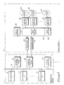
- FIG. 1 there is shown a system including an array of processors 1 coupling as external storage a synchronous DASD array 3.
- the processors 5, 7, 9 may be of the high performance variety. Attached external storage in the form of DASD array 3 is coupled to array 1 by way of adapter 15. Other information processing sources or sinks such as local area networks, printers, or displays would likewise be coupled over counterpart adapters 17.
- DAS 3 preferably comprises a RAID-type 4 or 5 DASD array and an associated DASD array controller (DAC) 23 as described for example in the Patterson reference and in European Patent Application No. 91304503.5.
- DAC DASD array controller
- an array controller (elements 19-31) coupling the host bus 11 by way of channel adapter 15.
- This path provides access to all system resources including memory 13 and global registers.
- Adapter 15 preferably attaches direct access storage (DAS) over a pair of simplex megabyte rate receive and transmit interfaces 19, 21.
- DAS direct access storage
- the interfaces may be OEMI or High Performance Parallel Interfaces (HIPPI) are described in the ANSI Draft Standard of 8/29/1989, X3T9/88-127, Revision 6.8.
- Data movement in the Host/DAS direction starts from internal memory 13 over bus 11 through adapter 15, receiver 19, ending in data buffer 22.
- the control logic determines from table memory 25, the device and block numbers that contain the old data and the old parity.
- the control logic then causes these blocks to be read via ECC circuits 27, 29, and 31. Each block is protected by appending ECC bytes for error detection and correction on an intra-block basis.
- Parity logic then calculates the new value of parity.
- table memory 25 DASD locations to write new data and parity are found according to one of the four variants of the method of this invention and the new data and parity blocks are written thereto. Finally, table memory 25 is updated to reflect the new locations of data and parity.
- Data movement in the DASD/processor host direction starts from DASD 33, 35, 37 through ECC circuits 27, 29, 31 to the data buffer 22.
- the data is then moved from the buffer through the transmitter to adapter 15 over bus 11 and to internal memory 13 of the processor host.
- a "parity group” is a unit of consistency and recovery. It comprises a predetermined number of data blocks defined over failure imdependant DASDs. It may also include one or more parity blocks from different DASDs. A parity block within the parity group contains the parity of all the data blocks in the parity groups. If a block from the parity group becomes unreadable, it can be recreated from the remaining blocks in that group.
- the term “column” is the synonym of the term “single parity group”. However, for the other variants, the term “column” is a synonym for the term "K parity groups”.
- parity tracks are reserved on a DASD to protect n data tracks from n other DASDs, but use only half of the blocks in the parity tracks at any given time.
- the parity now occupies 2/n times as much space as the data, for a storage efficiency of 1/(1 + 2/n).
- the two parity tracks P1 on DASD4 protect data on the three D1 tracks on DASDs 1,2 and 3.
- the example distributes the parity among the 5 DASDs in the array, although one could dedicate two DASDs out of the five to hold parity.
- the two parity tracks that protect three data tracks are stored on the same DASD (e.g., both P2 tracks are on DASD 5), but the two parity tracks of a column could be on two separate DASDs. Performance can be improved by putting both parity tracks of a column on the same DASD.
- the controller can use all tracks on all DASDs if T*C (the number of tracks per DASD) is an integer multiple of (n+2) and the number of columns is an integer multiple of the number of DASDs.
- Blocks B1, B5, B9 and parity block P1 constitute a "parity group" and there are four groups per column in the Table 3 example.
- each bitmap would occupy 8 bits, one for each parity block in the column, to indicate which blocks are empty and which are available When the system is initialized, the bit map would appear as
- a parity address table corresponding to the above bitmap would be expressed as 1,3,5,7
- parity for the first group of blocks is in P1
- the parity for the second group is in P3
- the parity for the third group is in P5
- the parity for the fourth group is in P7.
- the free space table contains redundant information. Yet, it is quicker to search when looking for a free block.
- the DAC first determines the column to which the block belongs, so it knows which parity address and free space tables to access. Then, it calculates that block B7 is part of group 3, and accesses the third entry in the parity address table. This entry is 5, and tells the DAC that parity for block B7 is currently in P5.
- the DAC now examines the free space table, looking for the nearest free block into which the new value of parity may be written. The nearest free block may be on either of the two parity tracks. From the free space table, the controller determines that P2 and P6 are both currently free, and that either location may be used to contain the new value of parity for the third group. It chooses P6, since it is adjacent to the current location P5.
- the reading of P5 and the writing of P6 is done in a single access to the disk containing the parity tracks for the column being updated. Two accesses are still required to the disk containing the data B7 - one to read the old value and one to write back the new value.
- the DAC modifies the parity, it updates the free space table to : and the parity address table to 1,3,6,7 to indicate that the parity of group 3 is now in P6 and that P5 is now available for use.
- the double parity method improves performance in two ways. First, it reduces the service time for the read and write of parity by almost an entire revolution of the DASD disk. Secondly, it reduces DASD utilization, since either the DASD can be released one revolution earlier than otherwise possible, or back-and-forth motion of the DASD arm caused by releasing the DASD before the write is eliminated. Path utilization is also reduced if the DAC 23 was otherwise reserving the path between the read and the write of parity. The combined effects of these factors is likely to be substantial.
- the DASD array controller DAC 23 may read the old parity and write the new parity in a single access if the time between these two events is short compared to an average access. The following calculation demonstrates this to be the case.
- the parity blocks in a column are free.
- the DAC 23 would determine if P3 or P7 were available.
- the system should be organized with both parity tracks of a column in the same physical cylinder. It is assumed that the DASDs use dedicated servo. If the DASDs use embedded servo, then head- switch times are quite long, and only P6 and P7 would be practical locations to write parity.
- the expected number of blocks to a free parity block is x + 2x(1-x) + 3x((1-x) ⁇ 2) + 4x((1-x) ⁇ 3) +... which is 1/x.
- the Floating Parity Track variant of the method offers higher storage efficiency than the Double Parity variant.
- all cylinders on every DASD in the array are designated as either parity cylinders, which contain only parity tracks, or as data cylinders, which contain only data tracks.
- Every parity cylinder contains parity data for T-1 columns (T is the number of tracks per cylinder).
- T is the number of tracks per cylinder.
- Each column consists of n data tracks from n different DASDs and a parity track (of m blocks) on yet another DASD.
- the m blocks in a parity track need not all be physically on the same track, as will be apparent shortly.
- Normally the space in a parity cylinder can store parity information for T columns.
- the floating parity track approach leaves m free blocks in the parity cylinder and uses them for enhancing performance.
- Pi on a DASD protects Di from each of four other DASDs.
- the second cylinder serves exclusively as a parity cylinder.
- the DAC 23 stores only three parity tracks on each parity cylinder, with the fourth track left free.
- Our example shows the floating parity track array implemented with distributed parity.
- Each DASD in the array must have TC / ( 1 + ( T / ( n * (T-1) ))) data tracks and TC - ( TC / ( 1 + ( T / ( n * (T-1) ))))) parity tracks.
- the number of data tracks and the number of parity tracks must both be multiples of T.
- B1 through B12 and P1 through P4 represents the first column
- B13 through B24 and P5 through P8 represents the second column
- B25 through B36 and P9 through P12 represents the third column.
- the parity of blocks B1, B5 and B9 is stored in P1, of blocks B2, B6 and B10 in P2, of blocks B3, B7 and B11 in P3 and of B4, B8 and B12 in P4.
- Blocks P5 through P8 contain parity for the data blocks B13 to B24, all of which are in the same column (P5 is the parity for B13, B17 and B21, etc.).
- P9 to P12 is the parity for the column of data blocks B25 through B36.
- P13 through P16 is initially free.
- the DAC 23 uses a 16-bit free space table (one bit for each block in the parity cylinder) for every parity cylinder on every DASD to indicate which blocks are empty and which are available.
- the free space table for one cylinder appears as:
- the DAC 23 also stores a parity address table per parity cylinder in the DASD array as follows: 1,2,3,4,5,6,7,8,9,10,11,12
- the parity address table contains m(T-1) entries, one for every group of blocks in every column whose parity is stored in the parity cylinder.
- the DAC 23 stores parity for three different columns in the same parity cylinder, and there are four groups of blocks in each of these three columns, requiring 12 entries in the parity address table.
- the parity address table indicates that parity for the first group of blocks from the first of three columns is in P1, parity for the second group of blocks from the first of three columns is in P2, and so on.
- the last entry indicates that parity for the last group of blocks in the third column is in P12.
- the DAC 23 first determines the column to which the block belongs, so it knows which parity cylinder contains the parity data for block B7. Thus, it knows which parity address and free space tables to access. It also figures out that the column of interest is the first of the three columns whose parity is mapped to that parity cylinder. Then, it calculates that block B7 is part of group 3, and accesses the third entry in the parity address table. This entry is 3, and tells the DAC 23 that parity for block B7 is currently in P3. From the free space table, the DAC 23 ascertains if one of P4, P8, P12 or P16 is free, and establishes that P16 is. Therefore, it chooses P16 as the new home for the parity information. If none of those four blocks had been free, the DAC 23 would next have looked to see if one of P1, P5, P9 or P13 were free, and so on.
- the DAC 23 now proceeds as follows:
- the DAC 23 reads P3 and writes P16 in a single access to the DASD containing the parity tracks for the column being updated.
- the DAC 23 still needs two accesses to the DASD rontaining the data B7 - one to read the old value and one to write back the new value.
- the DAC 23 updates the free space table to: and the parity address table to: 1,2,16,4,5,6,7,8,9,10,11,12 to indicate that the parity of the third group in the first column is now in P16 and that P3 is now available for use.
- the DAC 23 can read the old parity and write the new parity with a single access, since it has to wait only a short time between these two events, as shown by the following calculation. :
- a parity cylinder has m free blocks so that the probability that any one block is free is m/mT or 1/T.
- the new value of parity can be written one block away if any of P4, P8, P12 or P16 are free.
- the DAC 23 may write the new parity a single block away if any of T possible next blocks are free. This probability is: 1 -(( T-1 ) / T) ⁇ T
- the essence of the floating parity track method can be extended to include data tracks as well as parity tracks.
- One way to generalize the scheme is to leave a track (m blocks) free on every cylinder (a cylinder now has both data and parity tracks).
- Each column consists of n data tracks (of m blocks) from n different DASDs and a parity track (of m blocks) on yet another DASD.
- the m blocks in a track need not all be physically on the same track, as will be apparent shortly.
- Pi on a DASD protects Di from each of four other DASDs.
- One track from every cylinder is free, so that only (T- 1)*C tracks from each DASD are utilized.
- C*(T-1) / ( 1 + ( 1 / n )) are data tracks and the rest are parity tracks.
- the C unused tracks on every DASD count as overhead tracks that decrease storage efficiency.
- the number of data tracks and the number of parity tracks must both be multiples of T-1.
- a column is defined in terms of blocks rather than tracks -- n data blocks from n different DASDs and a parity block on yet another DASD.
- FIG 4 the cylinder and track layout for data and parity blocks over a DASD array according to the Floating Data and Parity Block variant of the method is laid out.
- Pi on a DASD protects Di from each of three other DASDs, but one block is left free in the cylinder. Only C(mT-1) blocks from each DASD are utilized. Of these, C * ( mT-1 ) / ( 1 + ( 1 / n)) are data blocks and the rest are parity blocks. The C unused blocks on every DASD count as overhead blocks and add to the number of parity blocks to determine the total overhead for this method. To use all blocks on all DASDs, the number of data blocks and the number of parity blocks must both be multiples of mT-1.
- the DAC 23 stores the parity of A1, B1 and C1 in D1, of A2, B2 and C2 in D2, and so on.
- the parity of A15, B15 and C15 is in D15, with A16, B16, C16 and D16 being left free.
- the free space tables illustratively appear as:
- the DAC 23 also stores a parity address table per cylinder in the DASD array which looks as below for our four cylinders.
- the parity address table indicates the current block within the cylinder at which it is stored.
- the DAC 23 determines that this block is stored at A3, and it then determines the cylinder containing the parity data for the block to be updated. The DAC 23 then accesses the parity address table for this cylinder and determines that parity is stored at D3. From the respective free space tables, the DAC 23 determines that A16 on the first cylinder and D16 on the last cylinder are free. On the DASD containing the first cylinder, the DAC 23 reads data from A3 and writes new data to A16 in a single access. Having obtained the value in A3, the DAC 23 next reads D3, calculates new parity and writes it into D16 in another access.
- the performance improvement of this variant over the traditional parity method is 1/2 a revolution in service time and reduced DASD utilization caused by the fact that the DASD can be released in 1/2 a revolution, rather than having to wait the entire revolution. If the path between the DASD and the DAC 23 is released between the read and the write, there is no reduction in the number of accesses needed over the traditional parity method.
- the Floating Parity Track variant can be extended to leave more than one track free per parity cylinder.
- the Floating Data and Parity Track variant can be extended to leave more than one track free per cylinder.
- the Floating Data and Parity Block variant can be extended to leave more than one block free per cylinder.
- the Floating Parity Track variant exhibits low parity overhead, low table (free space map, parity address table) overhead, and optimal performance.
- the two variants, Floating Parity Track and Floating Data and Parity Track are appropriate only for DASD arrays with fast head switching times.
- the other variants, Double Parity and Floating Data and Parity Block are operable with DASD arrays having slow head switching times.
- a method has been described which reduces the number of track rotations required to write modify a data block and alter the explicit parity of that group of data blocks containing the modified data block distributed across at least some of the DASDs in a DASD array.
- a method which utilizes DASD disk space to shadow write parity or data or both on a block, track, or cylinder level has also been described. Shadow writing rather than writing in place increases speed while management of the array sparing capacity ensures a high probability of a nearly instant free block extent to perform the shadow writing.
- the method variations include (1) Double Parity, (2) Floating Parity Track, (3) Floating Data and Parity Track, and (4) Floating Data and Parity Block.
- the Double Parity Method variant assumes N-2 accessed disk tracks, from N-2 different failure independent DASD and two parity tracks from another DASD.
- each DASD track supports K blocks/track.
- Each parity track stores K parity blocks defined over N-2 data blocks in column major order.
- the method write updates by first reading the old block and old parity in one track revolution. Next, it calculates the new parity (XOR of old values of data blocks and group parity and new data block value). During the second revolution of the DASD containing the data block, it writes the new data block in place. The new value of parity is shadow written in the first available table controlled free space on the parity tracks. Lastly, the tables are modified to indicate that the old parity block space is available.
- the Floating Parity Track Method variant extends double parity and models storage as N data cylinders from N failure independent DASD of T-1 tracks per cylinder at K blocks per track. Parity is organized as a cylinder of parity tracks. Each of the (T-1) tracks records K blocks of vertical parity of the counterpart data tracks from each of the N data cylinders. One parity track of K blocks is left free.
- the write update requires two track revolutions of the DASD containing the data block. One revolution to read the old data and one to write the new data in place. It also requires a fraction of a revolution to read the old parity and a fraction of a revolution to shadow write new parity in the first available place in the parity cylinder.
- the Floating Data and Parity Track Method variant extends the floating parity method by shadow writing both data and parity.
- This variant models storage as a cylinder of N synchronous tracks of M data blocks per track and a parity track of M blocks. All of the tracks are accessed from N+1 failure independent DASD's.
- the Floating Data and Parity Block Method variant extends the floating parity method by shadow writing both data and parity.
- This variant models storage as (N+1) data and parity cylinders, one from each of the (N+1) failure independent DASDs.
- Each cylinder has T tracks of K blocks per track.
- One track of K blocks is left free on each of the (N+1) cylinders.
- the K free blocks are table managed and may reside anywhere on the cylinders.
- the remaining (T-1) tracks or K*(T-1) blocks on each cylinder may contain either data or parity.
Landscapes
- Engineering & Computer Science (AREA)
- Theoretical Computer Science (AREA)
- Physics & Mathematics (AREA)
- General Engineering & Computer Science (AREA)
- General Physics & Mathematics (AREA)
- Quality & Reliability (AREA)
- Signal Processing (AREA)
- Human Computer Interaction (AREA)
- Detection And Correction Of Errors (AREA)
- Techniques For Improving Reliability Of Storages (AREA)
Abstract
A method for update writing in an array of DASDs (3) in a reduced number of DASD track cycles. The method involves distributing data and parity blocks for each parity group across the array in failure independent form and reserving unused space. During a first cycle, the old data and parity blocks are read. The new parity is calculated and shadow written into reserved unused space located before the old parity block recurs. The amended data is either written in place during a second cycle or shadow written into reserved space during a subsequent portion of the first cycle.
Description
- This invention relates to arrays of direct access storage devices (DASDs), and more particularly, to methods and means for reducing the number of track rotations required to write modify a data block and alter the explicit parity of a group of data blocks including any modified block distributed across at least some DASDs.
- Fast computers include DASD arrays as part of their storage subsystems. Array architecture, and organization and distribution of data influence operating performance, fault tolerance and the speed of data rebuild after a fault has occurred. The prior art shows that improvements in array performance turn on subtle tuning of array operations.
- A "storage subsystem" attaches a processor or processor array at its I/O boundary over a broadband data and control path. The subsystem may consist either of a single cyclic multitrack magnetic information storage device (DASD) individually accessed through its device adapter; several DASDs (denominated a "string") terminating in a common control unit; or an array of DASDs attached by a DASD array controller (DAC).
- A "DASD array" is any set of logically related DASDs operable by common mode or means. It includes any set of synchronously selected and operated DASDs. These are used where information is exchanged at a high data rate between fast processors and external storage. Serial to parallel mapping of data blocked at some predetermined size (byte, word, block) sustains the high data rate. The synchronous behavior requires N DASDs to rotate at the same rpm, have the same angular offset, and be simultaneously accessed in an identical manner. This solution while maximizing data transfer rate minimizes concurrency.
- Another type of DASD array comprises a set of DASD related together by the fact that data rendered unavailable through failure of any one DASD can be recovered through the use of redundancy such as parity stored on surviving DASD. Such an array need not necessarily be synchronously operated.
- Mathematically an "array" is a subscripted variable in which the subscript indexes the relative position order of each instance of the variable; specifically, the position order of each block in the logical track. The components of the subscript also define the dimensions of the array. Thus, array A(i,j) specifies a variable "A" whose relative positions are mapped onto a two dimensional closed integer intervals (1,1<(i,j)<N, K).
- The array dimensions may be mutually exclusive. Thus, the dimensions represented by the closed
integer intervals 1<i<N and 1<j<K could denote an ordering (indexing) of like devices and time respectively, N and K being integer upper bounds. By convention, column order designates one array dimension and row order designates the other. In this regard, N is the number of DASDs and K is the number of blocks per DASD per track thereof. - Any physical arrangement of N DASDs synchronously accessed constitutes a DASD array. Relatedly, the formatting and subsequent accessing of an array, as a store proceeds. By inserting values in consecutive positions on either a row or a column basis. If the operation is performed in a column direction, it is performed in "column major order". Likewise, if performed in a row direction, it is performed in "row major order".
-
- Storage subsystems are subject to fault or error. Relatedly, there are several strategies for returning such systems to a point of information consistency just prior the system faulting. These include
- (1) processing a transaction log from a known checkpoint,
- (2) duplication of the entire storage contents and backup switching, or
- (3) data reconstruction using special purpose codes and only a portion of the stored data.
- The first strategy relies upon log based recovery and emphasizes recreating event history. However, it inhibits current processing until completed.
- The second strategy of duplication of complete DASD contents does not require interruption of current operations. Yet, duplication (sometimes called mirroring) does require significant additional storage resource/cost even though only a small fraction of the data may be rendered unavailable.
- The third strategy, using coded data and minimizing additional storage, requires computational resources and a complex storage model. The special purpose coded information termed "parity" is stored on the DASD with the data and is redundant. For purposes of this invention, "parity" is defined to be any redundancy computationally usable with that portion of available data to recover an unavailable portion. It may include simple parity, Hamming, Reed-Solomon, ECC codes and the like.
- A distinction is drawn in the literature between "fault tolerance" and operation in "degraded mode". Also, a distinction is drawn between "fault", "error" and "erasure". For purposes of this invention, "tolerance" is the number of DASDs which could be made unavailable permitting continued operation of the system. "Degraded mode" designates the continued system operation after a fault. "Fault" is the occurrence of a permanent failure. "Error" is the occurrence of a false value in a data sequence often due to noise or a random or intermittent failure of software or hardware. Last, "erasure" designates the omission of any value in one or more positions in a data sequence.
- James N. Gray in "Notes on Database Operating Systems", Operating Systems- An Advanced Course, copyright 1979 Springer Verlag, pages 393-481 describes log based recovery for database and transaction management systems with pointers necessary to recreate history. This is necessary to roll back the system to a known point of prior consistency (checkpoint). After the rollback, the log drives the redo of the transactions.
- Patterson et al., "A Case for Redundant Arrays of Inexpensive Disks (RAID)", ACM SIGMOD Conference, Chicago, IL., June 1-3, 1988, and EP Application No. 91304503.5, filed 20 May 1991, "Method and Means for Accessing DASD Arrays with Tuned Data Transfer Rate and Concurrency" relate to recovery at the storage management level.
- Patterson et al. covers duplexing or "mirroring" data on array DASDs and parity encoding. In this regard, the mirroring of data stored on N array DASDs requires at least 2N DADs. As both Patterson and Brady point out, the combined use of parity encoding of a portion of the data, and an increase in the number of accesses per storage update use less than 2N DASDs.
- Brady et al also discloses the mapping of a sequential file of N*k data and parity blocks, K blocks per track per DASD, onto a two dimensional array (one spatial and one temporal dimension) by synchronously accessing N DASD's through counterpart controllers for the duration of one track revolution.
- Parity coding permits data to be rebuilt using only a portion of the stored data. It saves storage compared to the amount used in duplexing and saves time relative to log based recovery. The performance suffers by an increase in the number of accesses per write update. Ouchi and Clark first taught distributing data and parity blocks from the same logical file over attached DASDs as a fault tolerance and recovery aid.
- Ouchi, US-A- 4,092,732, "System For Recovering Data Stored In A Failed Memory Unit", issued on May 30, 1978. He disclosed the spreading of data blocks from the same logical file across a string of N-1 failure independent DASDs and recording a parity block on the Nth DASD. According to Ouchi, the parity block is a XORing (modulo 2 addition) of the binary coded contents of the N-1 other blocks. Contents from any single inaccessible DASD can be recovered by XORing the parity blocks with the blocks stored on the N-2 remaining accessible DASDs. A similar result can be obtained if the parity blocks are not available.
- Clark et al., US-A- 4,761,785, "Parity Spreading to Enhance Storage Access", issued August 2, 1988, modifies Ouchi by distributing parity blocks over DASDs such that the absence of one DASD (i.e. the parity DASD in Ouchi) would avoid rendering all parity blocks unavailable especially for operation in degraded mode. In this regard, Ouchi and Clark can tolerate up to one DASD failure and continue operation after rebuilding the data back.
-
- Patterson describes several different array architectures. His description and classification of data and DASD configuration into "levels" has become a de facto typology. That is, a given array is characterized as being a RAID Level 1 - 5.
- Patterson's
levels - Patterson's third level is one where read and write operations are synchronously made to N DASD's. In this arrangement, N-1 DASD's contain data and one DASD contains a parity ranging over the other data DASDs. That is, one check DASD is provided for the group. The contents of the failed DASD can be reconstructed in the manner of Ouchi. Parenthetically, he performs a logical record to physical track mapping and accessing onto a DASD array in column major order thereby accommodating both small and large access requests.
- The fourth level improves performance with respect to small read and write accesses. This is achieved by storing blocks along the column extent so that in a first time slot (DASD sector 1) blocks 1 to N can respectively be stored on
DASD 1 to N while in the second time slot (DASD sector 2) blocks N+1 to 2N are stored etc. In the Kth time slot (DASD sector K) blocks [(K-1)]*N+1 to KN are stored on corresponding devices. - Patterson's last and the fifth level distributes data and parity blocks across all array DASDs and encourages small reads and writes attending transaction processing as well- as large reads and writes attending numerically intensive computing.
-
RAID levels 3 to 5 may use at least one extra DASD for sparing in the event one of the array DASD faults. In this regard, reference may be made to Dunphy, US-A- 4,914,656, "Disk Drive Memory", issued April 3, 1990. - Assume that in a
RAID type 4 array of DASDs, the blocks D1, D2, D3, and D4 of a file are laid across four DASDs in any order and counterpart parity blocks P1-P4 are written on a parity DASD. The blocks are arranged in Table 1 as follows:
- P1 is the
modulo 2 addition (XOR) of D1 over DASD1-DASD4. P2, P3, and P4 cover D2, D3, and D4 respectively. If DASD1 were to fail its contents could be recreated on a spare DASD, by the XOR of the contents of DASD2-DASD5 - Whenever a storage subsystem (DASD array controller) receives a request to write a data block, it must also update the corresponding parity block for consistency. If D1 is to be altered, then P1 must be recalculated where:
new P1 := (old D1) XOR (new D1) XOR (old P1). - This requires four DASD array accesses in order to write modify or write update a data block. That is (1) read old data, (2) read old parity, (3) write new data , and (4) write new parity. It is the case, that the storage subsystem (array controller) writes the new data and parity in the same DASD locations as the old data and parity. This is termed "writing in place".
- It follows that the DASD locations are a full disk rotation away just after they have been read. Conventionally, the storage subsystem reserves both the DASDs and a path from the processor to the DASDs during the disk rotation interval between reading the old information and writing the new information. In a typical storage subsystem, there are provided four paths from the processor to a 32 or 64 DASD array. Path reservation between the old information read and the update write substantially reduces path concurrency. However, it may well mean that a path is not available when a write update is attempted.
- The present invention provides a method for updating information stored in failure independant form on disks in an array of direct access storage devices connected to a data processing system, said information being stored in the form of data blocks and corresponding parity blocks and at least one of said disks including a reserved portion of storage space, said method comprising the steps of:
reading a preselected data block from said disks;
writing an updated data block onto said disks;
reading an original parity block corresponding to said preselected data block during a former part of a disk revolution;
calculating a new parity block corresponding to said updated data block; and
writing said new parity block onto said reserved portion of storage space during the latter part of said revolution before said original parity block recurs. - Viewed from another aspect the present invention provides a data processing system including an array of direct access storage devices, information being stored in said direct access storage devices in the form of data blocks and corresponding parity blocks and said direct access storage devices including a reserved portion of storage space, said system including:
means for reading a preselected data block from disks in said direct access storage device;
means for writing an updated data block onto disks in said direct access storage device;
means for reading an original parity block corresponding to said preselected data block during a former part of a revolution of said disks;
means for calculating a new parity block corresponding to said updated data block; and
means for writing said new parity block onto said reserved portion of storage space during the latter part of said revolution of said disks before said original parity block recurs. - In order that the invention may he fully understood preferred embodiments thereof will now be described, by way of example only, with reference to the accompanying drawings in which:
- Figure 1 depicts data flow between a processor array and an external storage subsystem formed from a DASD array;
- Figure 2 illustrates the cylinder and track layout for data and parity blocks over a DASD array according to the Floating Parity Track variant of the method;
- Figure 3 shows the cylinder and track layout for data and parity blocks according to the Floating Data and Parity Track variant of the method ; and
- Figure 4 sets forth the cylinder and track layout for data and parity blocks over a DASD array according to the Floating Data and Parity Block variant of the method.
- Referring now to figure 1, there is shown a system including an array of
processors 1 coupling as external storage asynchronous DASD array 3. Theprocessors DASD array 3 is coupled toarray 1 by way ofadapter 15. Other information processing sources or sinks such as local area networks, printers, or displays would likewise be coupled overcounterpart adapters 17. -
DAS 3 preferably comprises a RAID-type - Referring again to figure 1, there is shown an array controller (elements 19-31) coupling the host bus 11 by way of
channel adapter 15. This path provides access to all systemresources including memory 13 and global registers.Adapter 15 preferably attaches direct access storage (DAS) over a pair of simplex megabyte rate receive and transmitinterfaces - Data movement in the Host/DAS direction starts from
internal memory 13 over bus 11 throughadapter 15,receiver 19, ending indata buffer 22. The control logic determines from table memory 25, the device and block numbers that contain the old data and the old parity. The control logic then causes these blocks to be read viaECC circuits DASD ECC circuits data buffer 22. The data is then moved from the buffer through the transmitter toadapter 15 over bus 11 and tointernal memory 13 of the processor host. - To assist exposition of the preferred embodiment, the following terms are employed:
- T
- number of tracks per cylinder
- C
- number of cylinders per DASD
- m
- number of blocks per track
- B
- block size in bytes
- d
- number of DASDs in the array
- n
- column size (number of data tracks per column)
- TS
- size of tables needed in DASD controller
- The following calculated quantities are used:
- Storage efficiency
- := 1/(1+1/n)
- Table overhead
- := TS/(size of data on DASDs)
- It should be appreciated that a "parity group" is a unit of consistency and recovery. It comprises a predetermined number of data blocks defined over failure imdependant DASDs. It may also include one or more parity blocks from different DASDs. A parity block within the parity group contains the parity of all the data blocks in the parity groups. If a block from the parity group becomes unreadable, it can be recreated from the remaining blocks in that group. For the Floating and Data Block variant to be described, the term "column" is the synonym of the term "single parity group". However, for the other variants, the term "column" is a synonym for the term "K parity groups".
- In this method, two parity tracks are reserved on a DASD to protect n data tracks from n other DASDs, but use only half of the blocks in the parity tracks at any given time. The parity now occupies 2/n times as much space as the data, for a storage efficiency of 1/(1 + 2/n). Consider an example expressed in Table 2 with five DASDs, each with one cylinder of five tracks, with one block per track and a column size of 3.

- The two parity tracks P1 on DASD4 protect data on the three D1 tracks on
DASDs - For the double parity scheme, with distributed parity and with both parity tracks of a column on the same DASD, the controller can use all tracks on all DASDs if T*C (the number of tracks per DASD) is an integer multiple of (n+2) and the number of columns is an integer multiple of the number of DASDs.
- To understand how the double party method works, consider a single column of 3 data tracks and 2 parity tracks, with four blocks per track as depicted in Table 3.

- Initially, the parity of blocks B1, B5 and B9 are stored in P1, of blocks B2, B6 and B10 in P3, of blocks B3, B7 and B11 in P5 and of B4, B8 and B12 in P7. Blocks B1, B5, B9 and parity block P1 constitute a "parity group" and there are four groups per column in the Table 3 example.
- Since blocks P2, P4, P6 and P8 are empty and available, the DAC must have a means to know which parity blocks are used and which are available. To accomplish this, the DAC maintains a bitmap, called a "free space table", for every column in the array. In the Table 3 example, each bitmap would occupy 8 bits, one for each parity block in the column, to indicate which blocks are empty and which are available When the system is initialized, the bit map would appear as

- To keep track of the storage location of the parity the DAC stores a "parity address table" per column. A parity address table corresponding to the above bitmap would be expressed as

- This indicates that the parity for the first group of blocks is in P1, the parity for the second group is in P3, the parity for the third group is in P5 and the parity for the fourth group is in P7.
- Given the existence of the parity address table, the free space table contains redundant information. Yet, it is quicker to search when looking for a free block.
- Consider an update to block B7. The DAC first determines the column to which the block belongs, so it knows which parity address and free space tables to access. Then, it calculates that block B7 is part of
group 3, and accesses the third entry in the parity address table. This entry is 5, and tells the DAC that parity for block B7 is currently in P5. The DAC now examines the free space table, looking for the nearest free block into which the new value of parity may be written. The nearest free block may be on either of the two parity tracks. From the free space table, the controller determines that P2 and P6 are both currently free, and that either location may be used to contain the new value of parity for the third group. It chooses P6, since it is adjacent to the current location P5. - The DAC now proceeds as follows:
- (1) Read old value from block B7.
- (2) Write new value of B7 whenever appropriate.
- (3) Read old value of P5.
- (4) In gap between P5 and P6, exclusive OR the old values of P5 and B7 with the new value to be written to B7.
- (5) Write this result to P6.
- The reading of P5 and the writing of P6 is done in a single access to the disk containing the parity tracks for the column being updated. Two accesses are still required to the disk containing the data B7 - one to read the old value and one to write back the new value. After the DAC modifies the parity, it updates the free space table to :

and the parity address table to
group 3 is now in P6 and that P5 is now available for use. - The double parity method improves performance in two ways. First, it reduces the service time for the read and write of parity by almost an entire revolution of the DASD disk. Secondly, it reduces DASD utilization, since either the DASD can be released one revolution earlier than otherwise possible, or back-and-forth motion of the DASD arm caused by releasing the DASD before the write is eliminated. Path utilization is also reduced if the
DAC 23 was otherwise reserving the path between the read and the write of parity. The combined effects of these factors is likely to be substantial. - In many systems, it is not practical to reserve the path from the DAC to the data DASD for the entire revolution between the read and the write of data because this path is shared among a large number of DASDs. Therefore, reading the old data block and writing the new data block would be accomplished with two DASD accesses. However, the DASD
array controller DAC 23 may read the old parity and write the new parity in a single access if the time between these two events is short compared to an average access. The following calculation demonstrates this to be the case. - At any time, 1/2 the parity blocks in a column are free. In our example, if P2 and P6 were both occupied, the
DAC 23 would determine if P3 or P7 were available. Preferably, the system should be organized with both parity tracks of a column in the same physical cylinder. It is assumed that the DASDs use dedicated servo. If the DASDs use embedded servo, then head- switch times are quite long, and only P6 and P7 would be practical locations to write parity. - There are several ways to ensure that both parity tracks of a column are on the same physical cylinder. One method is to isolate parity cylinders from data cylinders, and to use a DASD in which T (the number of tracks per cylinder) is a multiple of 2. The
controller DAC 23 would repeat this procedure until it found an available block for writing new parity. - The probability that a free parity block can be found in one block time is

- Assuming m (the number of blocks per track) is infinitely large and letting x be the probability that a free block is found one block away, the expected number of blocks to a free parity block is

- The Floating Parity Track variant of the method offers higher storage efficiency than the Double Parity variant. In the Floating Parity Track variant, all cylinders on every DASD in the array are designated as either parity cylinders, which contain only parity tracks, or as data cylinders, which contain only data tracks. Every parity cylinder contains parity data for T-1 columns (T is the number of tracks per cylinder). Each column consists of n data tracks from n different DASDs and a parity track (of m blocks) on yet another DASD. The m blocks in a parity track need not all be physically on the same track, as will be apparent shortly. Normally the space in a parity cylinder can store parity information for T columns. The floating parity track approach leaves m free blocks in the parity cylinder and uses them for enhancing performance.
- Referring now to figure 2, there is illustrated the cylinder and track layout for data and parity blocks over a DASD array according to the Floating Parity Track variant of the method. Figure 2 depicts an example using d=5 DASDs, each DASD with C=4 cylinders, T=4 tracks per cylinder and m=1 block per track. The column size is chosen as n=4.
- As before, Pi on a DASD protects Di from each of four other DASDs. On DASD1, the second cylinder serves exclusively as a parity cylinder. The
DAC 23 stores only three parity tracks on each parity cylinder, with the fourth track left free. Our example shows the floating parity track array implemented with distributed parity. Each DASD in the array must have
TC / ( 1 + ( T / ( n * (T-1) ))) data tracks and
TC - ( TC / ( 1 + ( T / ( n * (T-1) )))) parity tracks. - To use all tracks on all DASDs, the number of data tracks and the number of parity tracks must both be multiples of T.
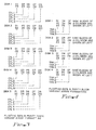
- Consider 3 columns, each with n = 3 data tracks + 1 parity track. Given a column number and knowledge of the placement algorithm used to store columns, the location of the parity track can be generated. Referring now to Table 4, there is shown an example using DASDs with T=4 tracks per cylinder and m=4 blocks per track. All three columns whose parity is stored in the same parity cylinder are shown.

- In the example of Table 4, B1 through B12 and P1 through P4 represents the first column, B13 through B24 and P5 through P8 represents the second column and B25 through B36 and P9 through P12 represents the third column. To start with, the parity of blocks B1, B5 and B9 is stored in P1, of blocks B2, B6 and B10 in P2, of blocks B3, B7 and B11 in P3 and of B4, B8 and B12 in P4. Blocks P5 through P8 contain parity for the data blocks B13 to B24, all of which are in the same column (P5 is the parity for B13, B17 and B21, etc.). Also, P9 to P12 is the parity for the column of data blocks B25 through B36. P13 through P16 is initially free. The
DAC 23 uses a 16-bit free space table (one bit for each block in the parity cylinder) for every parity cylinder on every DASD to indicate which blocks are empty and which are available. When theDAC 23 initializes the array, the free space table for one cylinder appears as:
- The
DAC 23 also stores a parity address table per parity cylinder in the DASD array as follows:
- The parity address table contains m(T-1) entries, one for every group of blocks in every column whose parity is stored in the parity cylinder. In the Table 4 example, the
DAC 23 stores parity for three different columns in the same parity cylinder, and there are four groups of blocks in each of these three columns, requiring 12 entries in the parity address table. - The parity address table indicates that parity for the first group of blocks from the first of three columns is in P1, parity for the second group of blocks from the first of three columns is in P2, and so on. The last entry indicates that parity for the last group of blocks in the third column is in P12.
- Consider an update to block B7. The
DAC 23 first determines the column to which the block belongs, so it knows which parity cylinder contains the parity data for block B7. Thus, it knows which parity address and free space tables to access. It also figures out that the column of interest is the first of the three columns whose parity is mapped to that parity cylinder. Then, it calculates that block B7 is part ofgroup 3, and accesses the third entry in the parity address table. This entry is 3, and tells theDAC 23 that parity for block B7 is currently in P3. From the free space table, theDAC 23 ascertains if one of P4, P8, P12 or P16 is free, and establishes that P16 is. Therefore, it chooses P16 as the new home for the parity information. If none of those four blocks had been free, theDAC 23 would next have looked to see if one of P1, P5, P9 or P13 were free, and so on. - The
DAC 23 now proceeds as follows: - (1) Read old value from block B7.
- (2) Write new value of B7 whenever appropriate.
- (3) Read old value of P3.
- (4) In gap between P3 and P16, exclusive OR the old values of P3 and B7 with the new value to be written to B7.
- (5) Write this result to P16.
- The
DAC 23 reads P3 and writes P16 in a single access to the DASD containing the parity tracks for the column being updated. TheDAC 23 still needs two accesses to the DASD rontaining the data B7 - one to read the old value and one to write back the new value. After the update of the parity is completed, theDAC 23 updates the free space table to:
and the parity address table to:
- As before, reading the old data block, and writing the new data block take two DASD accesses. However, the
DAC 23 can read the old parity and write the new parity with a single access, since it has to wait only a short time between these two events, as shown by the following calculation. : - At any time, a parity cylinder has m free blocks so that the probability that any one block is free is m/mT or 1/T. Consider again the update of P3. The new value of parity can be written one block away if any of P4, P8, P12 or P16 are free. The
DAC 23 may write the new parity a single block away if any of T possible next blocks are free. This probability is:
- For T=16, this probability is 0.644. Reasoning as before, the expected number of blocks to be searched until a free block is found is 1/0.644 or 1.55.
- The essence of the floating parity track method can be extended to include data tracks as well as parity tracks. One way to generalize the scheme is to leave a track (m blocks) free on every cylinder (a cylinder now has both data and parity tracks). Each column consists of n data tracks (of m blocks) from n different DASDs and a parity track (of m blocks) on yet another DASD. The m blocks in a track need not all be physically on the same track, as will be apparent shortly.
- Referring now to Figure 3, there is shown the cylinder and track layout for data and parity blocks according to the Floating Data and Parity Track variant of the method. In Figure 3, there is depicted an example using five DASDs, each DASD includes C=5 cylinders, T=3 tracks per cylinder, and m=1 block per track. A column size of n=4 has been chosen.
- As before, Pi on a DASD protects Di from each of four other DASDs. One track from every cylinder is free, so that only (T- 1)*C tracks from each DASD are utilized. Of these,

- Finally, consideration is given to a variant of the method in which a block is left free on every cylinder. In this variant, a column is defined in terms of blocks rather than tracks -- n data blocks from n different DASDs and a parity block on yet another DASD.
- Referring now to Figure 4, the cylinder and track layout for data and parity blocks over a DASD array according to the Floating Data and Parity Block variant of the method is laid out. In figure 4, an example is shown with a column size of n=3 using four DASDs, each DASD with C=1 cylinder, T=3 tracks per cylinder, and m=3 blocks per track.
- As before, Pi on a DASD protects Di from each of three other DASDs, but one block is left free in the cylinder. Only C(mT-1) blocks from each DASD are utilized. Of these,

- Consider the example below in Table 5 using four DASDs, each DASD having T=4 tracks per cylinder, and m=4 blocks per track. A column size of n=3 has been chosen.


- Four cylinders from four different DASDs are shown. The
DAC 23 stores the parity of A1, B1 and C1 in D1, of A2, B2 and C2 in D2, and so on. The parity of A15, B15 and C15 is in D15, with A16, B16, C16 and D16 being left free. There is a free space table for every cylinder on every DASD; each free space table has a single entry which indicates the location of the free block in the cylinder. At initialization, the free space tables illustratively appear as:
- The
DAC 23 also stores a parity address table per cylinder in the DASD array which looks as below for our four cylinders.
- For the 15 blocks in a cylinder containing either data or parity, the parity address table indicates the current block within the cylinder at which it is stored.
- Consider an update to the third block in the first of the four cylinders shown. From the parity address table for this cylinder, the
DAC 23 determines that this block is stored at A3, and it then determines the cylinder containing the parity data for the block to be updated. TheDAC 23 then accesses the parity address table for this cylinder and determines that parity is stored at D3. From the respective free space tables, theDAC 23 determines that A16 on the first cylinder and D16 on the last cylinder are free. On the DASD containing the first cylinder, theDAC 23 reads data from A3 and writes new data to A16 in a single access. Having obtained the value in A3, theDAC 23 next reads D3, calculates new parity and writes it into D16 in another access. - The final values of the free space tables are

and of the parity address tables are
- Since the free block in a cylinder could be anywhere, on the average there is a half revolution delay between the read and write of data or parity. It is debatable whether the read and the write can be done in a single access, since it may still be unacceptable to hold the path between DASD and
DAC 23 for half a revolution. - The performance improvement of this variant over the traditional parity method is 1/2 a revolution in service time and reduced DASD utilization caused by the fact that the DASD can be released in 1/2 a revolution, rather than having to wait the entire revolution. If the path between the DASD and the
DAC 23 is released between the read and the write, there is no reduction in the number of accesses needed over the traditional parity method. - Consider the following analysis of service time which is only valid at low I/O rates when there is no device queueing. For the traditional parity method, the time to read and then write a block on a DASD is
avg_seek + latency (.5 revolution) + 1 revolution + 1 block_write
and it is
avg_seek + latency (.5 revolution) +.5 revolution + 1 block_write
for the floating data and parity block method. Using 3 msecs for average seek, 16 msecs for a DASD revolution and 1 msec for a block write, the time to read and write a block is reduced from 28 msec to 20 msec. - The Floating Parity Track variant can be extended to leave more than one track free per parity cylinder. The Floating Data and Parity Track variant can be extended to leave more than one track free per cylinder. Lastly, the Floating Data and Parity Block variant can be extended to leave more than one block free per cylinder.
- Of the four variants, the Floating Parity Track variant exhibits low parity overhead, low table (free space map, parity address table) overhead, and optimal performance. The two variants, Floating Parity Track and Floating Data and Parity Track, are appropriate only for DASD arrays with fast head switching times. The other variants, Double Parity and Floating Data and Parity Block, are operable with DASD arrays having slow head switching times.
- Utilization of a storage subsystem formed from DASD arrays of
RAID type - A method has been described which reduces the number of track rotations required to write modify a data block and alter the explicit parity of that group of data blocks containing the modified data block distributed across at least some of the DASDs in a DASD array.
- Both the occupancy and concurrency of the path to the data through the storage subsystem have been enhanced.
- A method which utilizes DASD disk space to shadow write parity or data or both on a block, track, or cylinder level has also been described. Shadow writing rather than writing in place increases speed while management of the array sparing capacity ensures a high probability of a nearly instant free block extent to perform the shadow writing. The method variations include (1) Double Parity, (2) Floating Parity Track, (3) Floating Data and Parity Track, and (4) Floating Data and Parity Block.
- The Double Parity Method variant assumes N-2 accessed disk tracks, from N-2 different failure independent DASD and two parity tracks from another DASD. In this version, each DASD track supports K blocks/track. Each parity track stores K parity blocks defined over N-2 data blocks in column major order. Relatedly, there are 2K parity blocks (K per parity track) of which only K are in use at any one time, and K are free.
- The method write updates by first reading the old block and old parity in one track revolution. Next, it calculates the new parity (XOR of old values of data blocks and group parity and new data block value). During the second revolution of the DASD containing the data block, it writes the new data block in place. The new value of parity is shadow written in the first available table controlled free space on the parity tracks. Lastly, the tables are modified to indicate that the old parity block space is available.
- Illustratively, if p=0.5 is the population proportion of free parity blocks, then the probability of the availability of a free parity block can be found in 1 block time is

- The Floating Parity Track Method variant extends double parity and models storage as N data cylinders from N failure independent DASD of T-1 tracks per cylinder at K blocks per track. Parity is organized as a cylinder of parity tracks. Each of the (T-1) tracks records K blocks of vertical parity of the counterpart data tracks from each of the N data cylinders. One parity track of K blocks is left free.
- In the floating parity variant, the write update requires two track revolutions of the DASD containing the data block. One revolution to read the old data and one to write the new data in place. It also requires a fraction of a revolution to read the old parity and a fraction of a revolution to shadow write new parity in the first available place in the parity cylinder.
- The Floating Data and Parity Track Method variant extends the floating parity method by shadow writing both data and parity. This variant models storage as a cylinder of N synchronous tracks of M data blocks per track and a parity track of M blocks. All of the tracks are accessed from N+1 failure independent DASD's.
- Lastly, the Floating Data and Parity Block Method variant extends the floating parity method by shadow writing both data and parity. This variant models storage as (N+1) data and parity cylinders, one from each of the (N+1) failure independent DASDs. Each cylinder has T tracks of K blocks per track. One track of K blocks is left free on each of the (N+1) cylinders. The K free blocks are table managed and may reside anywhere on the cylinders. The remaining (T-1) tracks or K*(T-1) blocks on each cylinder may contain either data or parity.
Claims (8)
- A method for updating information stored in failure independant form on disks in an array of direct access storage devices connected to a data processing system, said information being stored in the form of data blocks and corresponding parity blocks and at least one of said disks including a reserved portion of storage space, said method comprising the steps of:
reading a preselected data block from said disks;
writing an updated data block onto said disks;
reading an original parity block corresponding to said preselected data block during a former part of a disk revolution;
calculating a new parity block corresponding to said updated data block; and
writing said new parity block onto said reserved portion of storage space during the latter part of said revolution before said original parity block recurs. - A method as claimed in Claim 1, wherein said updated data block is written onto a second reserved portion of storage space after said preselected data block has been read but during the same revolution as said preselected data block was read.
- A method as claimed in any of the preceding Claims, further comprising the step of:
signalling an address table in said data processing system whenever data is updated thereby maintaining a record of available reserved portions and parity blocks. - A method as claimed in any of the preceding Claims, wherein each of said disks contain either data blocks or parity blocks.
- A method as claimed in any of the preceding Claims, wherein said step of calculating a new parity block includes the step of calculating the modulo 2 addition of the original and updated data blocks and the original parity block.
- A method for updating information stored on a disk in a direct access storage device of a data processing system, said information being stored in the form of data blocks and corresponding parity blocks and said disk including a reserved portion of storage space, said method comprising the steps of:
reading a preselected data block on said disk;
writing an updated data block onto said disk;
reading an original parity block corresponding to said preselected data block during a former part of a revolution of said disk;
calculating a new parity block corresponding to said updated data block; and
writing said new parity block onto said reserved portion of said disk during the latter part of said revolution of said disk before said original parity block recurs. - A data processing system including an array of direct access storage devices, information being stored in said direct access storage devices in the form of data blocks and corresponding parity blocks and said direct access storage devices including a reserved portion of storage space, said system including:
means for reading a preselected data block from disks in said direct access storage device;
means for writing an updated data block onto disks in said direct access storage device;
means for reading an original parity block corresponding to said preselected data block during a former part of a revolution of said disks;
means for calculating a new parity block corresponding to said updated data block; and
means for writing said new parity block onto said reserved portion of storage space during the latter part of said revolution of said disks before said original parity block recurs. - A data processing system as claimed in Claim 6 further comprising:
means for signalling an address table in said data processing system whenever data is updated, thereby maintaining a record of available reserved portions and parity blocks.
Applications Claiming Priority (2)
| Application Number | Priority Date | Filing Date | Title |
|---|---|---|---|
| US07/600,034 US5375128A (en) | 1990-10-18 | 1990-10-18 | Fast updating of DASD arrays using selective shadow writing of parity and data blocks, tracks, or cylinders |
| US600034 | 1990-10-18 |
Publications (2)
| Publication Number | Publication Date |
|---|---|
| EP0481759A2 true EP0481759A2 (en) | 1992-04-22 |
| EP0481759A3 EP0481759A3 (en) | 1993-08-18 |
Family
ID=24402103
Family Applications (1)
| Application Number | Title | Priority Date | Filing Date |
|---|---|---|---|
| EP19910309534 Withdrawn EP0481759A3 (en) | 1990-10-18 | 1991-10-16 | Direct access storage device |
Country Status (3)
| Country | Link |
|---|---|
| US (1) | US5375128A (en) |
| EP (1) | EP0481759A3 (en) |
| JP (1) | JPH0642193B2 (en) |
Cited By (6)
| Publication number | Priority date | Publication date | Assignee | Title |
|---|---|---|---|---|
| EP0584804A2 (en) * | 1992-08-26 | 1994-03-02 | Mitsubishi Denki Kabushiki Kaisha | Redundant array of disks with improved storage and recovery speed |
| EP0606714A1 (en) * | 1992-12-11 | 1994-07-20 | International Business Machines Corporation | DASD array |
| US5522032A (en) * | 1994-05-05 | 1996-05-28 | International Business Machines Corporation | Raid level 5 with free blocks parity cache |
| EP0702302A3 (en) * | 1994-09-16 | 1996-07-10 | Int Computers Ltd | Disk array for data storage |
| US5566316A (en) * | 1994-02-10 | 1996-10-15 | Storage Technology Corporation | Method and apparatus for hierarchical management of data storage elements in an array storage device |
| US20230185479A1 (en) * | 2021-04-29 | 2023-06-15 | Micron Technology, Inc. | Memory sub-system refresh |
Families Citing this family (61)
| Publication number | Priority date | Publication date | Assignee | Title |
|---|---|---|---|---|
| JP2743606B2 (en) * | 1991-04-11 | 1998-04-22 | 三菱電機株式会社 | Array type recording device |
| US5636356A (en) * | 1992-09-09 | 1997-06-03 | Hitachi, Ltd. | Disk array with original data stored in one disk drive and duplexed data distributed and stored in different disk drives |
| US5819109A (en) * | 1992-12-07 | 1998-10-06 | Digital Equipment Corporation | System for storing pending parity update log entries, calculating new parity, updating the parity block, and removing each entry from the log when update is complete |
| JP3176157B2 (en) * | 1992-12-28 | 2001-06-11 | 株式会社日立製作所 | Disk array device and data updating method thereof |
| US5579474A (en) | 1992-12-28 | 1996-11-26 | Hitachi, Ltd. | Disk array system and its control method |
| US5761402A (en) * | 1993-03-08 | 1998-06-02 | Hitachi, Ltd. | Array type disk system updating redundant data asynchronously with data access |
| US5572660A (en) * | 1993-10-27 | 1996-11-05 | Dell Usa, L.P. | System and method for selective write-back caching within a disk array subsystem |
| US5533190A (en) * | 1994-12-21 | 1996-07-02 | At&T Global Information Solutions Company | Method for maintaining parity-data consistency in a disk array |
| US5748885A (en) * | 1994-12-23 | 1998-05-05 | Emc Corporation | Method and apparatus for reduction of I/O operations in persistent storage system |
| US5537534A (en) * | 1995-02-10 | 1996-07-16 | Hewlett-Packard Company | Disk array having redundant storage and methods for incrementally generating redundancy as data is written to the disk array |
| US5574882A (en) * | 1995-03-03 | 1996-11-12 | International Business Machines Corporation | System and method for identifying inconsistent parity in an array of storage |
| US5649093A (en) * | 1995-05-22 | 1997-07-15 | Sun Microsystems, Inc. | Server disk error recovery system |
| US5720029A (en) * | 1995-07-25 | 1998-02-17 | International Business Machines Corporation | Asynchronously shadowing record updates in a remote copy session using track arrays |
| US5684944A (en) * | 1995-08-14 | 1997-11-04 | Lubbers; Clark E. | Atomic update of EDC protected data |
| US5862312A (en) * | 1995-10-24 | 1999-01-19 | Seachange Technology, Inc. | Loosely coupled mass storage computer cluster |
| US6449730B2 (en) | 1995-10-24 | 2002-09-10 | Seachange Technology, Inc. | Loosely coupled mass storage computer cluster |
| US6067635A (en) * | 1995-10-27 | 2000-05-23 | Lsi Logic Corporation | Preservation of data integrity in a raid storage device |
| JP3713788B2 (en) * | 1996-02-28 | 2005-11-09 | 株式会社日立製作所 | Storage device and storage device system |
| US5857203A (en) * | 1996-07-29 | 1999-01-05 | International Business Machines Corporation | Method and apparatus for dividing, mapping and storing large digital objects in a client/server library system |
| US5864655A (en) * | 1996-09-09 | 1999-01-26 | International Business Machines Corporation | Managing removable media in raid and rail environments |
| KR100223186B1 (en) * | 1997-01-29 | 1999-10-15 | 윤종용 | Data recording method in dvd-ram |
| US5960169A (en) * | 1997-02-27 | 1999-09-28 | International Business Machines Corporation | Transformational raid for hierarchical storage management system |
| US6148368A (en) * | 1997-07-31 | 2000-11-14 | Lsi Logic Corporation | Method for accelerating disk array write operations using segmented cache memory and data logging |
| US6272662B1 (en) | 1998-08-04 | 2001-08-07 | International Business Machines Corporation | Distributed storage system using front-end and back-end locking |
| US6446237B1 (en) | 1998-08-04 | 2002-09-03 | International Business Machines Corporation | Updating and reading data and parity blocks in a shared disk system |
| US6332197B1 (en) * | 1998-08-04 | 2001-12-18 | International Business Machines Corp. | System for updating data in a multi-adaptor environment |
| US6128762A (en) * | 1998-08-04 | 2000-10-03 | International Business Machines Corporation | Updating and reading data and parity blocks in a shared disk system with request forwarding |
| US6446220B1 (en) | 1998-08-04 | 2002-09-03 | International Business Machines Corporation | Updating data and parity data with and without read caches |
| US6279138B1 (en) | 1998-08-04 | 2001-08-21 | International Business Machines Corporation | System for changing the parity structure of a raid array |
| US6769088B1 (en) * | 1999-06-30 | 2004-07-27 | Maxtor Corporation | Sector-coding technique for reduced read-after-write operations |
| KR100390853B1 (en) * | 2000-06-07 | 2003-07-10 | 차상균 | A Logging Method and System for Highly Parallel Recovery Operation in Main-Memory Transaction Processing Systems |
| US6990547B2 (en) * | 2001-01-29 | 2006-01-24 | Adaptec, Inc. | Replacing file system processors by hot swapping |
| US20020138559A1 (en) * | 2001-01-29 | 2002-09-26 | Ulrich Thomas R. | Dynamically distributed file system |
| US20020124137A1 (en) * | 2001-01-29 | 2002-09-05 | Ulrich Thomas R. | Enhancing disk array performance via variable parity based load balancing |
| US6754773B2 (en) | 2001-01-29 | 2004-06-22 | Snap Appliance, Inc. | Data engine with metadata processor |
| US6862692B2 (en) | 2001-01-29 | 2005-03-01 | Adaptec, Inc. | Dynamic redistribution of parity groups |
| US6990667B2 (en) | 2001-01-29 | 2006-01-24 | Adaptec, Inc. | Server-independent object positioning for load balancing drives and servers |
| US7054927B2 (en) | 2001-01-29 | 2006-05-30 | Adaptec, Inc. | File system metadata describing server directory information |
| US7062644B2 (en) * | 2001-05-30 | 2006-06-13 | International Business Machines Corporation | Method, system, and program for initializing a storage device comprising multiple storage units through a storage controller |
| US8402346B2 (en) | 2001-12-28 | 2013-03-19 | Netapp, Inc. | N-way parity technique for enabling recovery from up to N storage device failures |
| US7613984B2 (en) | 2001-12-28 | 2009-11-03 | Netapp, Inc. | System and method for symmetric triple parity for failing storage devices |
| US7640484B2 (en) * | 2001-12-28 | 2009-12-29 | Netapp, Inc. | Triple parity technique for enabling efficient recovery from triple failures in a storage array |
| KR100463841B1 (en) * | 2002-02-25 | 2004-12-29 | 한국전자통신연구원 | Raid subsystem and data input/output and rebuilding method in degraded mode |
| US7424637B1 (en) | 2003-03-21 | 2008-09-09 | Networks Appliance, Inc. | Technique for managing addition of disks to a volume of a storage system |
| US7664913B2 (en) * | 2003-03-21 | 2010-02-16 | Netapp, Inc. | Query-based spares management technique |
| US7386754B2 (en) * | 2003-10-16 | 2008-06-10 | Seagate Technology Llc | Method and apparatus to improve magnetic disc drive reliability using excess un-utilized capacity |
| US7328305B2 (en) * | 2003-11-03 | 2008-02-05 | Network Appliance, Inc. | Dynamic parity distribution technique |
| US7647451B1 (en) | 2003-11-24 | 2010-01-12 | Netapp, Inc. | Data placement technique for striping data containers across volumes of a storage system cluster |
| US7681104B1 (en) * | 2004-08-09 | 2010-03-16 | Bakbone Software, Inc. | Method for erasure coding data across a plurality of data stores in a network |
| US7681105B1 (en) * | 2004-08-09 | 2010-03-16 | Bakbone Software, Inc. | Method for lock-free clustered erasure coding and recovery of data across a plurality of data stores in a network |
| US8560503B1 (en) | 2006-01-26 | 2013-10-15 | Netapp, Inc. | Content addressable storage system |
| US7822921B2 (en) | 2006-10-31 | 2010-10-26 | Netapp, Inc. | System and method for optimizing write operations in storage systems |
| US7613947B1 (en) | 2006-11-30 | 2009-11-03 | Netapp, Inc. | System and method for storage takeover |
| US7647526B1 (en) | 2006-12-06 | 2010-01-12 | Netapp, Inc. | Reducing reconstruct input/output operations in storage systems |
| US20080183988A1 (en) * | 2007-01-30 | 2008-07-31 | Yanling Qi | Application Integrated Storage System Volume Copy and Remote Volume Mirror |
| US8209587B1 (en) | 2007-04-12 | 2012-06-26 | Netapp, Inc. | System and method for eliminating zeroing of disk drives in RAID arrays |
| US7975102B1 (en) | 2007-08-06 | 2011-07-05 | Netapp, Inc. | Technique to avoid cascaded hot spotting |
| US8132088B2 (en) * | 2007-08-14 | 2012-03-06 | Hewlett-Packard Development Company, L.P. | Data formatting in data storage |
| US8495417B2 (en) * | 2009-01-09 | 2013-07-23 | Netapp, Inc. | System and method for redundancy-protected aggregates |
| JP5598124B2 (en) * | 2010-07-09 | 2014-10-01 | 日本電気株式会社 | DATA RECORDING / REPRODUCING DEVICE, DATA RECORDING METHOD, AND DATA RECORDING PROGRAM |
| US8566673B2 (en) * | 2011-08-04 | 2013-10-22 | Lsi Corporation | Method for improving performance in RAID systems |
Citations (2)
| Publication number | Priority date | Publication date | Assignee | Title |
|---|---|---|---|---|
| EP0227530A1 (en) * | 1985-11-29 | 1987-07-01 | Michel Picard | Method for recording with updating and for the reproduction of data on a non-erasable sectorial record carrier |
| JPS63117369A (en) * | 1986-11-04 | 1988-05-21 | Nec Corp | Optical disk device |
Family Cites Families (9)
| Publication number | Priority date | Publication date | Assignee | Title |
|---|---|---|---|---|
| US4092732A (en) * | 1977-05-31 | 1978-05-30 | International Business Machines Corporation | System for recovering data stored in failed memory unit |
| JPS5637883A (en) * | 1979-09-04 | 1981-04-11 | Fanuc Ltd | Information rewrite system |
| US4375100A (en) * | 1979-10-24 | 1983-02-22 | Matsushita Electric Industrial Company, Limited | Method and apparatus for encoding low redundancy check words from source data |
| JPS60142418A (en) * | 1983-12-28 | 1985-07-27 | Hitachi Ltd | Input/output error recovery system |
| US4761785B1 (en) * | 1986-06-12 | 1996-03-12 | Ibm | Parity spreading to enhance storage access |
| US4989206A (en) * | 1988-06-28 | 1991-01-29 | Storage Technology Corporation | Disk drive memory |
| US4989205A (en) * | 1988-06-28 | 1991-01-29 | Storage Technology Corporation | Disk drive memory |
| US5088081A (en) * | 1990-03-28 | 1992-02-11 | Prime Computer, Inc. | Method and apparatus for improved disk access |
| US5130992A (en) * | 1990-04-16 | 1992-07-14 | International Business Machines Corporaiton | File-based redundant parity protection in a parallel computing system |
-
1990
- 1990-10-18 US US07/600,034 patent/US5375128A/en not_active Expired - Fee Related
-
1991
- 1991-07-16 JP JP3199910A patent/JPH0642193B2/en not_active Expired - Lifetime
- 1991-10-16 EP EP19910309534 patent/EP0481759A3/en not_active Withdrawn
Patent Citations (2)
| Publication number | Priority date | Publication date | Assignee | Title |
|---|---|---|---|---|
| EP0227530A1 (en) * | 1985-11-29 | 1987-07-01 | Michel Picard | Method for recording with updating and for the reproduction of data on a non-erasable sectorial record carrier |
| JPS63117369A (en) * | 1986-11-04 | 1988-05-21 | Nec Corp | Optical disk device |
Non-Patent Citations (1)
| Title |
|---|
| PATENT ABSTRACTS OF JAPAN vol. 12, no. 366 (P-765)30 September 1988 & JP-A-63 117 369 ( NEC CORP ) 21 May 1988 * |
Cited By (11)
| Publication number | Priority date | Publication date | Assignee | Title |
|---|---|---|---|---|
| EP0584804A2 (en) * | 1992-08-26 | 1994-03-02 | Mitsubishi Denki Kabushiki Kaisha | Redundant array of disks with improved storage and recovery speed |
| EP0584804A3 (en) * | 1992-08-26 | 1994-08-10 | Mitsubishi Electric Corp | Redundant array of disks with improved storage and recovery speed |
| US5517632A (en) * | 1992-08-26 | 1996-05-14 | Mitsubishi Denki Kabushiki Kaisha | Redundant array of disks with improved storage and recovery speed |
| US5644697A (en) * | 1992-08-26 | 1997-07-01 | Mitsubishi Denki Kabushiki Kaisha | Redundant array of disks with improved storage and recovery speed |
| EP0606714A1 (en) * | 1992-12-11 | 1994-07-20 | International Business Machines Corporation | DASD array |
| US5566316A (en) * | 1994-02-10 | 1996-10-15 | Storage Technology Corporation | Method and apparatus for hierarchical management of data storage elements in an array storage device |
| US5522032A (en) * | 1994-05-05 | 1996-05-28 | International Business Machines Corporation | Raid level 5 with free blocks parity cache |
| EP0702302A3 (en) * | 1994-09-16 | 1996-07-10 | Int Computers Ltd | Disk array for data storage |
| US5737741A (en) * | 1994-09-16 | 1998-04-07 | International Computers Limited | Disk array with parity data storage on the radially inner part of each disk |
| US20230185479A1 (en) * | 2021-04-29 | 2023-06-15 | Micron Technology, Inc. | Memory sub-system refresh |
| US11934690B2 (en) * | 2021-04-29 | 2024-03-19 | Micron Technology, Inc. | Memory sub-system refresh |
Also Published As
| Publication number | Publication date |
|---|---|
| US5375128A (en) | 1994-12-20 |
| EP0481759A3 (en) | 1993-08-18 |
| JPH0642193B2 (en) | 1994-06-01 |
| JPH04230512A (en) | 1992-08-19 |
Similar Documents
| Publication | Publication Date | Title |
|---|---|---|
| EP0481759A2 (en) | Direct access storage device | |
| US5526482A (en) | Storage device array architecture with copyback cache | |
| JP2951676B2 (en) | File system for multiple storage classes | |
| JP2959901B2 (en) | Redundant array of storage device and online reconfiguration method | |
| EP0485110B1 (en) | Logical partitioning of a redundant array storage system | |
| US5504858A (en) | Method and apparatus for preserving data integrity in a multiple disk raid organized storage system | |
| US7281089B2 (en) | System and method for reorganizing data in a raid storage system | |
| US5579475A (en) | Method and means for encoding and rebuilding the data contents of up to two unavailable DASDS in a DASD array using simple non-recursive diagonal and row parity | |
| US5488701A (en) | In log sparing for log structured arrays | |
| US7406621B2 (en) | Dual redundant data storage format and method | |
| US6247157B1 (en) | Method of encoding data signals for storage | |
| US5632012A (en) | Disk scrubbing system | |
| US5404361A (en) | Method and apparatus for ensuring data integrity in a dynamically mapped data storage subsystem | |
| US5572660A (en) | System and method for selective write-back caching within a disk array subsystem | |
| JP3302688B2 (en) | Logical Track Write Scheduling System for Parallel Disk Drive Array Data Storage Subsystem | |
| JP2902970B2 (en) | System and associated method for writing data to a disk array | |
| US5257362A (en) | Method and means for ensuring single pass small read/write access to variable length records stored on selected DASDs in a DASD array | |
| EP0606714A1 (en) | DASD array | |
| US6151685A (en) | System and method for recovering a segment directory for a log structured array | |
| EP0499365A2 (en) | Data processing system and method for encoding and rebuilding data contents of unavailable DASDS | |
| WO1993018455A1 (en) | Improved storage unit generation of redundancy information in a redundant storage array system | |
| US6343343B1 (en) | Disk arrays using non-standard sector sizes | |
| US20050193273A1 (en) | Method, apparatus and program storage device that provide virtual space to handle storage device failures in a storage system | |
| EP0632376B1 (en) | Encoding and rebuilding the data content of up to two unavailable DASDs in a DASD array | |
| KR19980047273A (en) | How to Manage Cache on RAID Level 5 Systems |
Legal Events
| Date | Code | Title | Description |
|---|---|---|---|
| PUAI | Public reference made under article 153(3) epc to a published international application that has entered the european phase |
Free format text: ORIGINAL CODE: 0009012 |
|
| AK | Designated contracting states |
Kind code of ref document: A2 Designated state(s): DE FR GB |
|
| 17P | Request for examination filed |
Effective date: 19920817 |
|
| PUAL | Search report despatched |
Free format text: ORIGINAL CODE: 0009013 |
|
| AK | Designated contracting states |
Kind code of ref document: A3 Designated state(s): DE FR GB |
|
| STAA | Information on the status of an ep patent application or granted ep patent |
Free format text: STATUS: THE APPLICATION HAS BEEN WITHDRAWN |
|
| 18W | Application withdrawn |
Withdrawal date: 19960826 |