EP0482503A2 - Mobile radio communication system having mobile base and portable devices as a mobile station - Google Patents
Mobile radio communication system having mobile base and portable devices as a mobile station Download PDFInfo
- Publication number
- EP0482503A2 EP0482503A2 EP91117668A EP91117668A EP0482503A2 EP 0482503 A2 EP0482503 A2 EP 0482503A2 EP 91117668 A EP91117668 A EP 91117668A EP 91117668 A EP91117668 A EP 91117668A EP 0482503 A2 EP0482503 A2 EP 0482503A2
- Authority
- EP
- European Patent Office
- Prior art keywords
- radio
- radio channel
- mobile base
- mss
- mobile
- Prior art date
- Legal status (The legal status is an assumption and is not a legal conclusion. Google has not performed a legal analysis and makes no representation as to the accuracy of the status listed.)
- Granted
Links
Images


Classifications
-
- H—ELECTRICITY
- H04—ELECTRIC COMMUNICATION TECHNIQUE
- H04W—WIRELESS COMMUNICATION NETWORKS
- H04W88/00—Devices specially adapted for wireless communication networks, e.g. terminals, base stations or access point devices
- H04W88/08—Access point devices
-
- H—ELECTRICITY
- H04—ELECTRIC COMMUNICATION TECHNIQUE
- H04W—WIRELESS COMMUNICATION NETWORKS
- H04W88/00—Devices specially adapted for wireless communication networks, e.g. terminals, base stations or access point devices
- H04W88/08—Access point devices
- H04W88/085—Access point devices with remote components
-
- H—ELECTRICITY
- H04—ELECTRIC COMMUNICATION TECHNIQUE
- H04B—TRANSMISSION
- H04B7/00—Radio transmission systems, i.e. using radiation field
- H04B7/24—Radio transmission systems, i.e. using radiation field for communication between two or more posts
- H04B7/26—Radio transmission systems, i.e. using radiation field for communication between two or more posts at least one of which is mobile
- H04B7/2603—Arrangements for wireless physical layer control
- H04B7/2606—Arrangements for base station coverage control, e.g. by using relays in tunnels
Definitions
- This invention relates to a radio communication system to be used as an automobile telephone system, a portable radio telephone system or a cordless telephone system and more particularly it relates to a radio communication system that enables installation of mobile base devices and portable device.
- a cellular type automobile telephone system has been known as a mobile ratio communication system.
- Such a system normally comprises a control station, a plurality of base stations and a plurality of mobile stations, of which the control station is connected to a wired telephone network by way of a wire communication path.
- the base stations are centered on different radio communication zones.
- Each of the mobile stations is connected by a radio channel to the base station of a radio communication zone where it is currently located and further to a wire telephone network by way of the base station and the control station.
- Such a known system normally employs a so-called frequency division multiple access (FDMA) technique for connection between a base station and each of the mobile stations that belong to it.
- FDMA is a technique with which a number of radio frequencies are shared by a base station and a plurality of mobile stations.
- the base station picks up an idle radio frequency whenever it calls or is called and then, if the call is successful, the calling and called stations are wirelessly connected by way of the picked up radio frequency.
- the operation of searching idle frequencies and assigning a particular frequency to a calling or called base station is conducted by the control station.
- each of the mobile stations of an automobile telephone system is equipped with an automobile telephone main unit and peripheral equipment including a handset assembly.
- An automobile telephone main unit comprises radio transmission circuits, control circuits and other circuits.
- a handset assembly normally comprises a cradle and a handset, which by turn comprises a telephone transmitter, a receiver and a console unit.
- a console unit by turn comprises dial key, hook switch, an LCD display and other components.
- the automobile telephone main unit and the handset assembly are connected by a signal cord.
- the cradle and the handset are connected by a curled cord.
- the curled cord can constitutes an annoying obstacle when the driver drives and speaks into the telephone transmitter simultaneously.
- the handset cannot be moved away beyond a limit posed by the curled wire, meaning that a passenger sitting on the front or rear passenger seat is compelled to stand up or take a crouching posture if he or she wants to speak over the phone.
- the automobile telephone main unit While the handset assembly of a conventional mobile station is placed within the passenger cabin of a car, the automobile telephone main unit is normally arranged in the trunk of the car.
- the signal cord connecting the telephone main unit and the handset assembly should be carefully arranged so as not to aesthetically damage the appearance of the car, entailing a troublesome work to be done within a narrow space of the car.
- Another object of the present invention is to provide a mobile radio communication system that can appropriately allocate radio channels for secure communication between base stations and mobile base devices and between mobile base devices and portable devices without causing interference and other troubles among radio channels.
- a mobile radio communication system comprising a base station to be connected with a communication network by way of a wired communication path, a mobile base device, to be connected with the base station by way of a first radio channel selected from a plurality of first radio channels, and a portable device to be connected with the mobile base device by way of a second radio channel selected from a plurality of second radio channels.
- Said mobile base device is provided with first, second and third connection control means.
- the mobile base device cooperates with the base station to search an idle radio channel out of the first radio channels by using the first connection means so that the base station and the mobile base device are mutually connected by of the idle first radio channel.
- the second connection means is used to search an idle radio channel out of the second radio channels that has a cer-tain relationship with the time slot of the selected idle first radio channel so that the mobile base device and a portable device are mutually connected by way of said selected idle second radio channel.
- the third con-nection means is used to connect the selected first and second radio channels to establish a communication through path between the base station and the portable device.
- a radio channel can be established not only between the base station and a mobile base device but also between a mobile base device and a portable device for mutual communication. If such a system is used for automobile telephone, connection between an automobile telephone main unit that operates as a mobile base device and a handset assembly that constitutes a portable device does not involve a signal cord nor curled cord to consequently enhance the maneuverability of the telephone handset and eliminate any possible nuisance to the driver due to the curled cord. Moreover, with such a system, a passenger on the rear seat can speak into the telephone transmitter of the handset without leaving the seat. Since no signal cord needs to be laid between an automobile telephone main unit and a handset assembly, the work of installing an automobile telephone terminal can be significantly simplified.
- a second radio channel is selected as a function of the time slot of a selected first radio channel. Therefore, the selected second radio channel is always appropriate for a secure communication path between the base station and the portable device and never constitutes a source of interference and/or other troubles.
- the effect of a mobile radio communication system according to the invention will be particularly remarkable when the transmission time slot of the first radio channel and that of the second radio channel are selected with a difference of timing so that any two different operations of signal transmission may not take place simultaneously in a mobile base device and consequently occurrence of any undesirable spurious transmission output may be effectively avoided.
- the peak value of energy consumption by a mobile base device may be reduced to alleviate the load for power supply.
- a system according to the invention may find a variety of applications.
- a mobile base device may be constituted by an automobile telephone main unit installed in a car and a portable device may correspond to a portable radio telephone handset to be used with the main unit in a mobile radio communication system according to the invention.
- the portable radio telephone handset is connected with the automobile telephone main unit by a radio channel to set up a communication channel leading to a telephone network.
- a conventional portable radio telephone handset arranged in a car normally needs to be taken out of the car and placed somewhere outside the car or an adaptor should be put to it in order to make it operable relative to a matching telephone main unit in the car.
- a portable radio telephone handset of a system according to the invention does not require to be placed outside the car nor does it need an adaptor to be put on it to become operable.
- a mobile base device may be constituted by a stationary unit of a codeless telephone system while a portable device may correspond to a codeless telephone handset.
- stationary telephone units are connected to a telephone exchange by way of subscribers' wire lines and each of the stationary units is connected a handset by way of a radio channel.
- additional stationary telephone units can be wirelessly connected to a telephone exchange without incurring any additional cost of installing new subscribers' lines and/or removing existing subscribers' lines.
- a mobile base device and a portable device may respectively correspond to an automobile telephone main unit and a codeless telephone handset.
- a codeless telephone handset whose service area is normally limited to the inside of a home or an office can be used in a car.
- a mobile base device searches out of the second radio channels a plurality of idle radio channels having a particular relationship with a single first radio channel in order to accommodate a number of portable devices to be connected to said first radio channel whenever such a search operation is requested by portable devices. Then, the mobile base device is firstly connected with the request issuing portable device by way of the selected respective second radio channels, which are subsequently connected with the first radio channel.
- those connected portable device can be branched from a wired telephone terminal of a telephone network and jointly participate in a common telephone talk that takes place among the connected terminals.
- a mobile base device searches out of the second radio channels a plurality of idle radio channels to accommodate a number of portable devices to be mutually connected whenever such a search operation is requested by portable devices. Then, the mobile base device is connected with the request issuing portable devices by way of the selected respective second radio channels so that any two or more than two portable devices may be put through to one another.
- portable devices that belong to a mobile base device can operate as so many extension terminals branched from a local switch board, which is in fact a mobile base device.
- the length of a time slot in a second radio channel is made longer than the length of a time slot in a first radio channel.
- the number of time slots comprised in a time frame of a second radio channel is made smaller than that of time slots comprised in a time frame of a first radio channel.
- a fixed communication device at least capable of calling other subscribers is connected to a mobile base device by way of a cable line for talking.
- a fixed communication device may be operated in different modes, in one possible mode, the fixed communication device and a wired telephone terminal is connected by way of a first radio channel and a telephone network.
- the fixed communication device and a portable device is connected by way of a second radio channel to use the portable device as an extension terminal.
- a portable device and a wired telephone terminal connected to a telephone network are mutually connected to establish a communication path and then a fixed communication device is further connected to the establish communication path so that the three terminals can jointly participate in a telephone talk.
- Fig. 1 shows a schematic view of a first embodiment of the mobile radio communication system of the invention, which is an automobile telephone system.
- This embodiment comprises as components a number of base stations BSS1 through BSSn and mobile stations MS1 through MSm.
- Said base stations BSS1 through BSSn are connected to a wire telephone network NW by way of respective cable lines CL1 through CLn and centered in different radio zones E1 through En.
- Each of the mobile stations MS1 through MSm comprises a mobile base device MSS and a portable device PSS.
- the mobile base device MSS is connected to a base station BSS that covers the radio zone E where it is located by way of a first radio channel, whereas the portable device PSS is connected to the mobile base device MSS by way of a second radio channel.
- This embodiment utilizes a FDMA/TDMA technique for connection between a base station and a mobile base device as well as for connection between a mobile base device MSS and a portable device PSS.
- a FDMA/TDMA technique a number of radio frequencies are shared by a plurality of stations. These radio frequen-cies has a time division signal unit format where a time frame is divided into a number of time slots, e.g., six time slots TS1 through TS6.
- the system searches an idle radio frequency and then an idle time slot of the radio frequency and assigns the selected time slot to the calling and called stations to establish a radio telephone communication channel between these stations.
- stationary base stations BSS1 through BSSn, mobile base devices MSS and portable devices PSS of this embodiment will be described further for their configurations.
- Fig. 2 showing a block diagram of a portable device PSS to be used for the embodiment, it comprises a transmission system, a reception system and a control system.
- Reference numeral 40 denotes a power source, which is a battery.
- the transmission system comprises a telephone transmitter 11, a speech encoder (SPCOD) 12, an error correction encoder (CHCOD) 13, a digital modulator (MOD) 14, a multiplier 15, a power amplifier (PA) 16, a high frequency switch circuit (SW) 17 and an antenna 18.
- the speech encoder 12 encodes analog speech signals coming from the telephone transmitter 11 into coded signals.
- the error correction encoder 13 detects and corrects errors in coded speech signals coming from the speech encoder 12 and encoding control signals coming from a control circuit 31, which will be described later.
- the digital modulator 14 generates intermediate frequency signals and causes them to be modulated by encoded speech signals coming from the error correction encoder 13 before sending them out.
- a method called ⁇ /4 shifted differentially encoded quadrature phase shift keying is typically used for modulation in the modulator 14. Then, in the multiplier 15, intermediate frequency signals generated by the digital modulator 14 are mixed with local oscillation signals transmitted from a frequency synthesizer 32 and then subjected to a frequency conversion process to produce radio transmission signals having a frequency that matches the frequency of the assigned radio channel.
- the power amplifier 16 amplifies the power of radio transmission signals coming from the multiplier 15 to a predetermined transmission power level.
- the high frequency switch circuit 17 is a switch circuit which is closed only for the period of each transmission time slot assigned by the control circuit 31. Only in this period, radio transmission signals coming from said power amplifier 16 are forwarded to the antenna 18, which sends out them to a corresponding base station BSS.
- the reception system comprises a receiver (RX) 21, a digital demodulator (DEM) 22, an error correction decoder (CH-DEC) 23, a speech decoder (SP-DEC) 24 and a telephone receiver or earphone 25.
- High frequency signals received by the receiver 21 in each predetermined time slot are converted for frequency into intermediate frequency signals in the receiver 21.
- the information used for bit- and frame-synchronization in the digital demodulator 22 is fed to the control circuit 31.
- the error correction decoder 23 decodes demodulated coded signals coming from said digital demodulator for error correction.
- Coded speech signals from said error correction modulator 23 are fed to the speech demodulator 24, while coding control signals from the error correction modulator 23 are sent to the control circuit 31.
- the coded speech signals are decoded in the speech decoder 24 to reproduce analog speech signals, which are sent out of the telephone receiver 25 in audible loud voice.
- control system comprises a control circuit (CONT) 31, a frequency synthesizer (SYN) 32, a received electric field strength sensor circuit (RSSI) 33 and a console unit (CU) 34.
- the frequency synthesizer generates an oscillation having a local oscillation frequency that matches the radio channel specified by the control circuit 31.
- the received electric field strength sensor circuit 33 senses the received field strength of the electric wave transmitted from the base station BSS it belongs and sends signals representing the determined field strength to the control circuit 31.
- the console unit 34 comprises transmission switches, dial keys, a liquid display panel and so on.
- the control circuit is normally a microcomputer that comprises a central processing unit (CPU), an input port, an output port, a program ROM and a data RAM.
- the CPU executes control operations according to the programs stored in the program ROM.
- a mobile base device MSS it comprises a first transmitter receiver unit 50 and a second transmitter-receiver unit 80.
- the first transmitter-receiver unit 50 is used for radio communication with the base station BSS it belongs by way of a first radio channel
- the second transmitter-receiver unit 80 is used for radio communication with its portable device PSS by way of a second radio channel.
- the first transmitter-receiver unit 50 comprises a transmission system, reception system and a control system.
- the transmission system is constituted by a register circuit (STR) 51, a speech encoder (SPCOD) 52, an error correction encoder (CHCOD) 53, a digital modulator (MOD) 54, a multiplier 55, a power amplifier (PA) 56, a high frequency switch circuit (SW) 57 and an antenna 58.
- the register circuit 51 temporarily stores digital speech signals sent from the reception system of the second transmitter-receiver unit 80, which will be described in more detail later.
- the speech encoder 52 changes the data signaling rate for digital speech signals coming from said register circuit 51.
- the error correction encoder 53 detects errors in digital speech signals from said speech encoder 52 and digital control signals from a control circuit 71, which will be described later.
- the digital modulator 54 generates intermediate frequency signals and causes them to be modulated by encoded speech signals coming from the error correction encoder 53 before sending them out. A method called ⁇ /4 shifted QPSK is typically used for modulation in the modulator 54.
- the multiplier 55 intermediate frequency signals generated by the digital modulator 54 are mixed with local oscillation signals transmitted from a frequency synthesizer 72 and then subjected to a frequency conversion process to produce radio transmission signals having a frequency that matches the frequency of the assigned radio channel.
- the power amplifier 56 amplifies the power of radio transmission signals coming from the multiplier 55 to a predetermined transmission power level.
- the high frequency switch circuit 57 is a switch circuit which is closed only for the period of each transmission time slot assigned by the control circuit 71. Only in this period, radio transmission signals coming from said power amplifier 56 are forwarded to the antenna 58, which sends out them to a corresponding base station BOSS.
- the reception system comprises a receiver (RX) 61, a digital demodulator (DEM) 62, an error correction decoder (CHDEC) 63, a speech decoder (SPDEC) 64 and a register circuit (STR) 65.
- RX receiver
- DEM digital demodulator
- CHDEC error correction decoder
- SPDEC speech decoder
- STR register circuit
- the digital demodulator 62 after establishing bit synchronization and frame-synchronization for the incoming intermediate frequency signals from said receiver 61, demodulates them into coded speech signals.
- the signals used bit- and frame-synchronization are fed to the control circuit 71.
- the error correction decoder 63 decodes demodulated coded signals coming from said digital dulator for error correction. Coded speech signals from said error correction modulator 63 are fed to the speech demodulator 64, while coding control signals from the error correction modulator 63 are sent to the control circuit 71.
- the speech decoder 64 changes the data signaling rate for digital speech signals coming from error correction decoder 63 and the digital speech signals whose data signaling rate has been changed are temporarily stored in the register circuit 65 and then sent out to the second transmitter-receiver unit 80.
- control system comprises a control circuit (CONT) 71, a frequency synthesizer (SYN) 72 and a received electric field strength sensor circuit (RSSI) 73.
- the control circuit 71 has a main control section which is normally a microcomputer and execute control operations for connecting a base station BSS and a portable device PSS.
- the frequency synthesizer generates under the control of the control circuit 71 an oscillation having a local oscillation frequency required for radio communication with the base station it belongs.
- the received electric field strength sensor circuit 33 senses the received field strength of the electric wave transmitted from the base station BSS it belongs and sends signals representing the determined field strength to the control circuit 31.
- the second transmitter-receiver unit 80 also comprises a transmission system, reception system and a control system.
- the transmission system is constituted by a speech encoder (SPCOD) 82, an error correction encoder (CHCOD) 83, a digital modulator (MOD) 84, a multiplier 85, a power amplifier (PA) 86, a high frequency switch circuit (SW) 87 and an antenna 88.
- SPCOD speech encoder
- CHCOD error correction encoder
- MOD digital modulator
- PA power amplifier
- SW high frequency switch circuit
- the reception system comprises a receiver (RX) 91, a digital demodulator (DEM) 92, an error correction decoder (CHDEC) 93 and a speech decoder (SPDEC).
- the control system comprises a frequency synthesizer 102 and a received electric field strength sensor circuit 103.
- the frequency synthesizer 102 generates under the control of the control circuit 71 an oscillation having a local oscillation frequency required for radio communication with its portable device PSS.
- the received electric field strength sensor circuit 103 senses the received field strength of the electric wave transmitted from the portable device PSS and sends signals representing the determined field strength to the control circuit 71.
- the transmission system is constituted by a speech encoder (SPCOD) 112, an error correction encoder (CHCOD) 113, a digital modulator (MOP) 114, a multiplier 115, a power amplifier (PA) 116, a high frequency switch circuit (SW) 117 and an antenna 118.
- the speech encoder 112 encodes speech signals coming from the wire telephone network NW by way of a cable line CL.
- the error correction encoder 113 detects and corrects errors in digital speech signals from said speech encoder 112 and digital control signals from a control circuit 131, which will be described later.
- the digital modulator 114 generates intermediate frequency signals and causes them to be modulated by encoded speech signals coming from the error correction encoder 53 before sending them out.
- a method called ⁇ /4 shifted QPSK is typically used for modulation in the modulator 114.
- signals modulated in said modulator 114 are mixed with local oscillation signals transmitted from a frequency synthesizer 132 and then subjected to a frequency conversion process to produce radio transmission signals having a frequency that matches the frequency of the assigned radio channel.
- the power amplifier 116 amplifies the power of radio transmission signals coming from the multiplier 115 to a predetermined transmission power level.
- the high frequency switch circuit 117 is a switch circuit which is closed only for the period of each transmission time slot assigned by the control circuit 131. Only in this period, radio transmission signals coming from said power amplifier 116 are forwarded to the antenna 118, which sends out them to a target mobile base device out of the mobile base device MSS1 through MSSm for which it is responsible.
- the reception system comprises a receiver (RX) 121, a digital demodulator (DEM) 122, an error correction decoder (CHDEC) 123, a speech decoder (SPDEC) 124 and a telephone receiver 125.
- RX receiver
- DEM digital demodulator
- CHDEC error correction decoder
- SPDEC speech decoder
- a telephone receiver 125 high frequency radio signals received by way of the antenna 118 and the high frequency switch circuit 117 in each predetermined time slot are converted for frequency into intermediate frequency signals.
- the digital demodulator 122 after establishing bit-synchro-nization and frame-synchronization for the incoming intermediate frequency signals from said receiver 121, demodulate them into coded speech signals.
- the signals used bit- and frame-synchronization are fed to the control circuit 131.
- the error correction decoder 123 decodes demodulated coded signals coming from said digital demodulator 122 for error correction. Coded speech signals from said error correction modulator 123 are fed to the speech decoder 124, while coding control signals from the error correction modulator 123 are sent to the control circuit 131.
- the speech decoder 124 decodes digital speech signals coming from said error correction decoder 123 and decoded analog signals from said speech decoder 124 are sent out to a cable line CL by way of the hybrid circuit 111.
- control system comprises a control circuit (CONT) 131, a frequency synthesizer (SYS) 132 and a received electric field strength sensor circuit (RSSI) 133.
- the control circuit 131 has a main control section which is normally a microcomputer and executes control operations for connecting the base station BSS with a first radio channel.
- the frequency synthesizer 132 generates under the control of the control circuit 131 an oscillation having a local oscillation frequency that matches the radio channel specified by the control circuit 131.
- the received electric field strength sensor circuit 133 senses the received field strength of the electric wave transmitted from the mobile base device MSS and sends signals representing the determined field strength to the control circuit 131.
- the embodiment having a configuration as described above operates in the following manner.
- the portable device PSS Assume now that a person at mobile station MS2 located in radio zone E2 covered by base station BSS2 has turned on the call request switch on the console unit 34 of the portable device PSS that belongs to the mobile station MS2. Then, the portable device PSS generates a call signal containing the ID code of the station and sends the signal to the mobile base device MSS of the mobile station MS2 by way of a control channel.
- the mobile base device MSS Upon receiving the call signal from the portable device PSS, the mobile base device MSS searches an idle radio channel to be used for communication between itself and the base station BSS.
- radio frequency fR1 has an idle time slot as a result of the search operation. Then, the mobile base device MSS detects a synchronous word out of the signals being received through time slot TS1 which is currently busy in the radio frequency fR1 and determines the position of the idle time slot, say time slot TS2, referring to the position of the synchronous word.
- the data for the position of the idle time slot TS2 as well as the date for the radio frequency fR1 are stored in the RAM of the control circuit 71.
- the control circuit 72 controls the frequency synthesizer 72 to establish a control channel C-CH and generates an originating signal that contains data for the position of the idle time slot and those for the radio frequency to be used for reception as well as the ID code of the mobile base device MSS, which originating signal is then sent to the base station BSS by way of the control channel C-CH.
- a preallocated control radio frequency is used for the control channel.
- the base station BSS2 or any base station in general which is in a standby state, constantly monitors incoming call signals from the wired telephone network NW and call signals originating from any of the mobile stations MS1 through MSm it covers. If, now, it detects a call signal originating from the mobile base device of mobile station MS2 under this condition, the base station BSS2 generates an answer signal containing the ID code of the calling mobile base device MSS and sends it to the mobile base device MSS by way of the control channel C-CH.
- the mobile base device MSS at the other end of the control channel C-CH waits for the answer signal from the base station BSS2, observing a predetermined period of time from the transmission of the call signal. If it receives the answer signal within the predetermined period of time from the transmission of the call signal, it controls the transmission and reception systems on the basis of the stored radio frequency fR1 in such a way that signals are sent out only during the allocated transmission time period of time slots TS2 of the assigned radio frequency fT1 and it receives signals only during the allocated time period of time slots TS2 of the assigned radio frequency fR1.
- the mobile base device MSS If, on the other hand, the mobile base device MSS does not receive an answer signal with a predetermined period of time after the transmission of the call signal, it judges that the tried radio frequency and time slot are busy and are not currently available to establish a telephone channel. It then goes on the operation of searching an idle time radio frequency and an idle time slot.
- the base station BSS2 After transmitting the answer signal, the base station BSS2 controls its reception and transmission systems in such a manner that it operates for signal reception during the reception time period of time slots TS2 of the assigned radio frequency fT1 and for signal transmission during the transmission time period of time slots TS2 of the assigned radio frequency fR1 as shown in Fig. 5.
- the base station BSS2 and the mobile base device MSS of the mobile station MS2 are mutually connected by way of a first radio channel having radio frequencies fT1 and fR1 and time slot TS2 available for telephone communication between the two stations.
- the mobile base device MSS operates to search an idle second radio channel that matches the established first radio channel. Firstly, it sequentially tries radio frequencies allotted to it for telephone communication between the mobile base device MSS and the portable device PSS, say three radio frequencies fRA, fRB and fRC, to find out a radio frequency having an idle time slot available for signal reception. If, for instance, it is found that radio frequency fRA has an idle time slot available for reception, it picks up an idle time slot which is in the matching radio frequency fTA to be used for signal transmission and located behind the time slot in the reception radio channel by a predetermined length of time.
- the predetermined length of time is the time required for the mobile base device MSS to transmit a digital signal to the portable device PSS by its second transmitter-receiver unit 80 after receiving the signal from the base station BSS2 by its first transmitter-receiver unit 50 and can be equal to the length of two time slots.
- the selection of time slots for the signal transmission radio frequency fTA will be as shown in Fig. 5.
- the mobile portable device MSS After selecting the time slot TS2 for signal transmission, the mobile portable device MSS generates an answer signal that contains data for specifying the time slot TS2 and the radio frequency fTA for signal transmission and the ID code of the portable device PSS and send it to the portable device PSS by way of the control channel. After sending the answer signal, it controls its reception and transmission systems in such a manner that it operates for signal transmission during the transmission time period of time slots TS2 that follows and signal reception during the reception time period of time slots that follows.
- the portable device PSS at the other end of the control channel waits for the answer signal from the mobile base device MSS, observing a predetermined period of time from the transmission of the call signal. If it receives the answer signal within the predetermined period of time from the transmission of the call signal, it controls the transmission and reception systems on the basis of the data for specifying the radio channel contained in the answer signal in such a way that signals are sent out only during the allocated transmission time period of time slots TS2 of the assigned radio frequency fTA and it receives signals only during the allocated time period of time slots TS2 of the assigned radio frequency fRA.
- the portable device PSS and the mobile base device MSS are mutually connected by way of a second radio channel having radio frequencies fTA and fRA and time slot TS2 available for telephone communication between the two stations as shown in Fig. 5.
- the second radio channel and the first radio channel that has been established between the mobile base device MSS and the base station BSS2 are mutual connected within the mobile base device MSS to establish a telephone communication path running all the way from the portable device PSS and the base station BSS2 and using the first and second radio channels.
- the person at the portable device PSS now can call the terminal at the other end of the line and talk with the person there.
- a base station BSS and a mobile base device MSS can be mutually connected by way of a radio channel
- a cable line or a curled cord is not required for connecting the telephone main unit and the handset of a mobile station. Therefore, a speaker in an automobile equipped with such a mobile station is exempt from positional as well as postural limitations that used to exist with a conventional automobile telephone set so that a large degree of freedom of movement is allowed to the speaker in the car, which will be particularly appreciated in a large vehicle such as a chartered bus.
- the present embodiment has a feature of differentiating the timing of the selected transmission time slot of the first radio channel and that of the selected transmission time slot of the second radio channel so that the two radio channels do not operate synchronously to eliminate any possibility of generating undesired spurious conditions for signal transmission and reduce the peak value of energy consumption for the power source. Since the feature of timing differentiation is also provided for reception time slots, the four radio channels involved in a telephone communication between a portable device PSS and a base station BSS are protected against any mutual interferences to secure a high quality of radio telephone communication.
- Fig. 6 illustrates the basic concept of a second embodiment of the invention.
- base station BSS2 and mobile base device MSS are connected with each other by way of time slots TS2 of radio frequencies fT1 and fR1 and that said mobile base device MSS and a first portable device PSS1 are connected with each other by way of time slots TR3 and TR4 of radio frequencies fTA and fRA so that the line is currently busy.
- the portable device PSS2 transmits a call signal to the mobile base device MSS by way of the control channel.
- the mobile base device MSS constantly monitors incoming call signals except when it receives radio signals from the first portable device PSS1. If the call signal from the second portable device PSS2 arrives under this condition, the mobile base device MSS starts an operation of assigning a radio channel to the portable device PSS2.
- the mobile base device MSS searches an idle time slot in the reception radio frequency fRA when it does not receive radio signals from the first portable device PSS1. If it finds an idle time slot, it then determines if it is an appropriate time slot or not.
- An appropriate time slot here means that it is delayed relative to the busy reception time slot TS2 of the first radio channel by at least a predetermined time length and does come during the busy transmission time slot TS2 of the first radio channel.
- the predetermined time length here means a time length required for the mobile base device MSS to receive a signal from the base station BSS2 and forward it to the portable device PSS2.
- the mobile base device MSS finds that time slot TS5 of reception radio frequency fRA is idle and appropriate. Then, the mobile base device MSS generates an answer signal containing data necessary to specify transmission time slot TS4 of transmission radio frequency fTA that corresponds to the transmission time slot TS5 and the ID code of the portable device PSS2 and sends the answer signal to the portable device PSS2 by way of the control channel. Once the answer signal is sent out, the transmission time slot TS4 becomes busy as the currently busy transmission time slot TS3. Similarly, the reception time slot TS5 becomes busy just as the currently busy reception time slot TS4 of the reception radio frequency fRA.
- the portable device PSS2 at the other end of the control channel waits for the answer signal from the mobile base device MSS, observing a predetermined period of time from the transmission of the call signal. If it receives the answer signal within the predetermined period of time from the transmission of the call signal, it controls the transmission and reception systems on the basis of the data for specifying a channel contained in the answer signal in such a way that it receives signals only during the allocated time period of time slots TS4 of the assigned radio frequency fTA and signals are sent out from it only during the allocated transmission time period of time slots TS5 of the assigned radio frequency fRA.
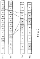
- the portable device PSS2 and the mobile base device MSS are mutually connected by way of a radio channel having a transmission time slot TS4 of a radio frequency fTA and a reception time slot TS5 of a radio frequency fRA as shown in Fig. 7.
- the radio channel is connected with the first radio channel that has been established between the mobile base device MSS and the base station BSS2, to which the radio channel between the first portable device PSS1 and the mobile base device MSS is already connected.
- the terminal at the other end of the line can be commonly shared by both the portable device PSS1 and the portable device PSS2 for telephone communication.
- the line connecting the base station BSS2 and the mobile base device MSS can be branched to connect both the portable device PSS1 and the portable device PSS2 with the base station BSS2.
- the number of time slots to be used in a time frame of a radio frequency for communication between a mobile base device MSS and a portable device PSS is smaller than the number of time slots in a time frame of a radio frequency for communication between a base station BSS and a mobile base device MSS.
- the reason for this is that the line traffic between the mobile base device MSS and the portable device PSS is lower than the line traffic between the base station BSS and the mobile base device MSS and therefore a large line capacity is not needed for communication between the mobile base device MSS and the portable device PSS.
- the bit rate for digital data transmission can be held low so that a CPU having a relatively slow processing speed may be used for the control circuit 31 of the portable devices PSS1 and PSS2 to reduce the cost of the control circuit.
- part of a first transmitter-receiver unit of a mobile base device for radio communication with a base station is used for a second transmitter-receiver unit of the mobile base device for radio communication with a portable devices.
- Fig. 8 shows a block diagram of a mobile base device of this embodiment.
- the components which are identical with the corresponding components of the first embodiment shown in Fig. 3 are indicated by same reference numerals.
- the mobile base device of this embodiment has only a control circuit 171, a frequency synthesizer 172, a reception electric field strength sensor circuit 173, a transmission-reception multiplier 155, a power amplifier 156, a high frequency switch 157, an antenna 158 and a receiver 161, which are shared by both the first and second transmitter-receiver units.
- the control circuit 171 controls the allocation of transmission and reception time slots for radio communication with the base station and that of transmission and reception time slots for radio communication with the portable device PSS so that the former and latter time slots do not come simultaneously.
- Speech encoders 52 and 82, speech decoders 64 and 94 and register circuits 54 and 65 of the first and second transmitter-receiver units are respectively formed as single integral audio codes, each of which typically comprises a digital signal processor (DSP) 140.
- DSP digital signal processor
- a radio signal is sent out from the base station by way of a reception time slot of a first radio channel. Then, the radio signal is received by the receiver 161 by way of the antenna 158 and the audio switch 157 during the reception time slot and then decoded by digital decoder 62. The decoded digital signal is then corrected for errors by error correction decoder 63, converted for speed by the audio decoder 64 and temporarily stored in the register circuit 65. The digital speech signal stored in the register circuit 65 is read out during transmission time slots allocated for the portable device. The read out digital speech signal is then converted for speed by the speech encoder 82, corrected for errors by error correction encoder 83 and then converted into a modulated signal by digital modulator 84.
- the modulated signal is mixed with a local oscillation signal generated by the frequency synthesizer in the multiplier 155 to become a radio transmission signal.
- the power level of the radio transmission signal is amplified by the power amplifier 156 and then transmitted to the portable device by way of the high frequency switch 157 and the antenna 158.
- the power level of the signal coming out from the power amplifier 156 is set to a relatively low value because of the short distance between the mobile base device and the portable device.
- a radio signal transmitted by the portable device by way of a reception time slot of a second radio channel is received by the receiver 161 by way of the antenna 158 and the high frequency switch 157 in said reception time slot and then demodulated by digital demodulator 92.
- the demodulated digital speech signal is corrected for errors by error correction decoder 93, read out during the transmission time slot for signal transmission to the base station and converted for speed by the speech decoder 52 before it is corrected for errors by error correction encoder 53 and converted into modulated signal by the digital modulated 54.
- the modulated signal is then mixed with a local oscillation signal generated by the frequency synthesizer in the multiplier 155 to become a radio transmission signal.
- the power level of the radio transmission signal is amplified by the power amplifier 156 and then sent out to the base station by way of the high frequency switch 157 and the antenna 158.
- the power level of the signal coming out from the power amplifier 156 is set to a relatively high value because of the long distance that normally exists between the mobile base device and the base station.
- the overall configuration of the mobile base device is very simplified so that it may be made very compact and light weight.
- a mobile base device is connected with a handset by way of a cord such as a curled cord to allow telephone communication to take place by way of the handset.
- Fig. 9 shows a block diagram of the embodiment.
- handset 200 comprises as integral components thereof a telephone transmitter 201, a telephone receiver 202 and a console unit (CU) 203.
- the console unit 203 is provided with dial keys, signal transmission switches and an LCD unit.
- switch circuits 66, 67 are arranged respectively on the input signal path of register circuit 51 and the output signal path of register circuit 65 of a first transmitter-receiver unit 50'. These switch circuits 66, 67 operate under the control of control circuit 71'.
- a request for calling a wired telephone terminal of a wire telephone network NW is made by means of the console unit 203 of the handset 200.
- the switch circuits 66, 67 are respectively connect the telephone speaker 201 and the telephone receiver 202 of the handset 200 with the respective register circuits 51, 65 under the control of the control circuit 71'.
- the control circuit 71' searches an idle first radio channel and operates to establish a communication path between the wired telephone terminals and the handset which plays the role of a subscribers telephone set.
- the switch circuits 66, 67 respectively connect the telephone speaker 201 and the telephone receiver 202 of the handset 200 with speech decoder 94 and speech encoder 82.
- the control circuit 71' searches an idle 2nd radio channel and operates to establish a communication path between the handset 200 and the portable device, which plays the role of an extension terminal.
- the switch circuits 66, 67 When a portable device is connected with a wired telephone terminal by way of a communication path including first and second radio channels, the switch circuits 66, 67 respectively connect the register circuits 51, 65 with the speech decoder 94 and the speech encoder 82. If a request for branching the line is made by using the console unit 203 of the handset 200 under this condition, the switch circuits 66, 67 respectively connect the telephone transmitter 201 and the telephone receiver 202 to the respective communication paths that have been established between the register circuits 51, 65 and the speech decoder 94 and the speech encoder 82 respectively, without disconnecting the communication paths under the control of the control circuit 71'. Consequently, the handset 200 can be used as a branched terminal.
- the switch circuits 66, 67 connect the telephone transmitter 201 and the telephone receiver 202 of the handset 200 to the communication path between the two portable devices to allow a three party communication.
- a FDMA/TDMA technique is employed for radio channels connecting base stations and mobile base devices as well as mobile base devices and portable devices
- a FDMA or TDMA technique may be used in its place.
- a FDMA/TDMA technique may be used for connection between base stations and mobile base devices, while a FDMA or TDMA technique us used for connecting mobile base devices and portable devices.
- a mobile base device MSS searches an idle time slot before it transmits signals to a base station BSS in any of the above described embodiments
- the present invention is not limited to such a mode of operation.
- each of the base stations BSSs may search idle time slots since it can completely control and fully exploit all idle time slots of the radio frequencies. assigned to it.
- a more simple method of coding and modulation may be used for communication between a mobile base device and a portable device than for communication between a base station and a mobile base device because the communication path between the mobile base device and the portable device is normally shorter than the path between the base station and the mobile base device and therefore the rate of errors in signals due to high speed fading phenomena is smaller in the former path.
- a system according to the invention may be applied to a codeless telephone system that normally comprises stationary units connected to subscribers' lines of a wire telephone network and codeless telephone sets connected to the respective stationary units by way of radio channels, where the stationary units corresponds to the mobile base devices and the codeless telephone sets correspond to the portable devices of the above embodiments.
- Base stations are also provided and connected to a wire telephone network.
- Each of the stationary units is connected to one of the base stations by way of a first radio channel, whereas each of the stationary units is connected to its codeless radio telephone set by way of a second radio channel.
- a system according to the invention may comprise automobile telephone main units that operate as mobile base devices and portable radio telephone sets that operate as portable devices, each of the telephone main units being connected with a corresponding portable radio telephone set by way of a second radio channel.
- codeless telephone sets may be used for portable devices.
Abstract
Description
- This invention relates to a radio communication system to be used as an automobile telephone system, a portable radio telephone system or a cordless telephone system and more particularly it relates to a radio communication system that enables installation of mobile base devices and portable device.
- A cellular type automobile telephone system has been known as a mobile ratio communication system. Such a system normally comprises a control station, a plurality of base stations and a plurality of mobile stations, of which the control station is connected to a wired telephone network by way of a wire communication path. The base stations are centered on different radio communication zones. Each of the mobile stations is connected by a radio channel to the base station of a radio communication zone where it is currently located and further to a wire telephone network by way of the base station and the control station.
- Such a known system normally employs a so-called frequency division multiple access (FDMA) technique for connection between a base station and each of the mobile stations that belong to it. FDMA is a technique with which a number of radio frequencies are shared by a base station and a plurality of mobile stations. For communication between a base station and a mobile station, the base station picks up an idle radio frequency whenever it calls or is called and then, if the call is successful, the calling and called stations are wirelessly connected by way of the picked up radio frequency. The operation of searching idle frequencies and assigning a particular frequency to a calling or called base station is conducted by the control station.
- Now, each of the mobile stations of an automobile telephone system is equipped with an automobile telephone main unit and peripheral equipment including a handset assembly. An automobile telephone main unit comprises radio transmission circuits, control circuits and other circuits. A handset assembly normally comprises a cradle and a handset, which by turn comprises a telephone transmitter, a receiver and a console unit. A console unit by turn comprises dial key, hook switch, an LCD display and other components. The automobile telephone main unit and the handset assembly are connected by a signal cord. The cradle and the handset are connected by a curled cord.
- With such an arrangement, the curled cord can constitutes an annoying obstacle when the driver drives and speaks into the telephone transmitter simultaneously. Moreover, the handset cannot be moved away beyond a limit posed by the curled wire, meaning that a passenger sitting on the front or rear passenger seat is compelled to stand up or take a crouching posture if he or she wants to speak over the phone.
- While the handset assembly of a conventional mobile station is placed within the passenger cabin of a car, the automobile telephone main unit is normally arranged in the trunk of the car. The signal cord connecting the telephone main unit and the handset assembly should be carefully arranged so as not to aesthetically damage the appearance of the car, entailing a troublesome work to be done within a narrow space of the car.
- It is therefore an object of the present invention to provide a mobile radio communication system that wirelessly connects not only between a base station and a mobile station but also between a mobile station, or a mobile base device, and a portable device by a radio channel in order to eliminate the necessity of wiring the mobile base device and portable device and enhance the maneuverability of an automobile telephone handset.
- Another object of the present invention is to provide a mobile radio communication system that can appropriately allocate radio channels for secure communication between base stations and mobile base devices and between mobile base devices and portable devices without causing interference and other troubles among radio channels.
- According to the invention, the above objects are achieved by providing a mobile radio communication system comprising a base station to be connected with a communication network by way of a wired communication path, a mobile base device, to be connected with the base station by way of a first radio channel selected from a plurality of first radio channels, and a portable device to be connected with the mobile base device by way of a second radio channel selected from a plurality of second radio channels. Said mobile base device is provided with first, second and third connection control means. The mobile base device cooperates with the base station to search an idle radio channel out of the first radio channels by using the first connection means so that the base station and the mobile base device are mutually connected by of the idle first radio channel. Then, the second connection means is used to search an idle radio channel out of the second radio channels that has a cer-tain relationship with the time slot of the selected idle first radio channel so that the mobile base device and a portable device are mutually connected by way of said selected idle second radio channel. The third con-nection means is used to connect the selected first and second radio channels to establish a communication through path between the base station and the portable device.
- In a mobile radio communication system according to the invention and having a configuration as described above, a radio channel can be established not only between the base station and a mobile base device but also between a mobile base device and a portable device for mutual communication. If such a system is used for automobile telephone, connection between an automobile telephone main unit that operates as a mobile base device and a handset assembly that constitutes a portable device does not involve a signal cord nor curled cord to consequently enhance the maneuverability of the telephone handset and eliminate any possible nuisance to the driver due to the curled cord. Moreover, with such a system, a passenger on the rear seat can speak into the telephone transmitter of the handset without leaving the seat. Since no signal cord needs to be laid between an automobile telephone main unit and a handset assembly, the work of installing an automobile telephone terminal can be significantly simplified.
- According to the invention, a second radio channel is selected as a function of the time slot of a selected first radio channel. Therefore, the selected second radio channel is always appropriate for a secure communication path between the base station and the portable device and never constitutes a source of interference and/or other troubles.
- The effect of a mobile radio communication system according to the invention will be particularly remarkable when the transmission time slot of the first radio channel and that of the second radio channel are selected with a difference of timing so that any two different operations of signal transmission may not take place simultaneously in a mobile base device and consequently occurrence of any undesirable spurious transmission output may be effectively avoided. Besides, the peak value of energy consumption by a mobile base device may be reduced to alleviate the load for power supply.
- A system according to the invention may find a variety of applications. In a first conceivable application of a system according to the invention, a mobile base device may be constituted by an automobile telephone main unit installed in a car and a portable device may correspond to a portable radio telephone handset to be used with the main unit in a mobile radio communication system according to the invention. The portable radio telephone handset is connected with the automobile telephone main unit by a radio channel to set up a communication channel leading to a telephone network. It is a known fact that a conventional portable radio telephone handset arranged in a car normally needs to be taken out of the car and placed somewhere outside the car or an adaptor should be put to it in order to make it operable relative to a matching telephone main unit in the car. A portable radio telephone handset of a system according to the invention, however, does not require to be placed outside the car nor does it need an adaptor to be put on it to become operable.
- Alternatively in a second possible application that uses a system according to the invention for a cordless telephone system, a mobile base device may be constituted by a stationary unit of a codeless telephone system while a portable device may correspond to a codeless telephone handset. In a codeless telephone system, stationary telephone units are connected to a telephone exchange by way of subscribers' wire lines and each of the stationary units is connected a handset by way of a radio channel. With a system according to the invention, additional stationary telephone units can be wirelessly connected to a telephone exchange without incurring any additional cost of installing new subscribers' lines and/or removing existing subscribers' lines.
- In a third possible application of a system according to the invention, a mobile base device and a portable device may respectively correspond to an automobile telephone main unit and a codeless telephone handset. With such an arrangement, a codeless telephone handset whose service area is normally limited to the inside of a home or an office can be used in a car.
- In preferable embodiment of the invention, a mobile base device searches out of the second radio channels a plurality of idle radio channels having a particular relationship with a single first radio channel in order to accommodate a number of portable devices to be connected to said first radio channel whenever such a search operation is requested by portable devices. Then, the mobile base device is firstly connected with the request issuing portable device by way of the selected respective second radio channels, which are subsequently connected with the first radio channel. With such an arrangement, those connected portable device can be branched from a wired telephone terminal of a telephone network and jointly participate in a common telephone talk that takes place among the connected terminals.
- In another preferred embodiment of the invention, a mobile base device searches out of the second radio channels a plurality of idle radio channels to accommodate a number of portable devices to be mutually connected whenever such a search operation is requested by portable devices. Then, the mobile base device is connected with the request issuing portable devices by way of the selected respective second radio channels so that any two or more than two portable devices may be put through to one another. With such an arrangement, portable devices that belong to a mobile base device can operate as so many extension terminals branched from a local switch board, which is in fact a mobile base device.
- In still another preferred embodiment of the invention, the length of a time slot in a second radio channel is made longer than the length of a time slot in a first radio channel. In other words, the number of time slots comprised in a time frame of a second radio channel is made smaller than that of time slots comprised in a time frame of a first radio channel. With such an arrangement, the bit rate of data transmitted by way of a second radio channel can be set to a relatively low level to allow the use of a CPU having a relatively low processing speed in a portable device. The circuit configuration of such a portable device can be made rather simple to reduce the cost of the station. Since the volume of traffic between a mobile base device and a portable device is by far smaller than that of traffic between a base station and a mobile base device, a radio channel connecting them does not need to have a large channel capacity. Therefore, a relatively small number of time slots in a second radio channel would not give rise to a channel shortage condition.
- In a still another preferred embodiment of the invention a fixed communication device at least capable of calling other subscribers is connected to a mobile base device by way of a cable line for talking. Such a fixed communication device may be operated in different modes, in one possible mode, the fixed communication device and a wired telephone terminal is connected by way of a first radio channel and a telephone network. In another possible mode, the fixed communication device and a portable device is connected by way of a second radio channel to use the portable device as an extension terminal. In still another possible mode, a portable device and a wired telephone terminal connected to a telephone network are mutually connected to establish a communication path and then a fixed communication device is further connected to the establish communication path so that the three terminals can jointly participate in a telephone talk.
- This invention can be more fully understood from the following detailed description when taken in conjunction with the accompanying drawings, in which:
- Fig. 1 is a schematic view of a first embodiment of the mobile radio communication system of the invention, illustrating its basic concept;
- Fig. 2 is a block diagram showing the configuration of a portable device of the embodiment of Fig. 1;
- Fig. 3 is a block diagram showing the configuration of a mobile base device of the embodiment of Fig. 1;
- Fig. 4 is a block diagram showing the configuration of a base station of the embodiment of Fig. 1;
- Fig. 5 is a timing chart to be used for selecting first and second radio channels in the embodiment of Fig. 1;
- Fig. 6 is a schematic view of a second embodiment of the mobile radio communication system of the invention, illustrating its basic concept;
- Fig. 7 is a timing chart to be used for selecting first and second radio channels in the embodiment of Fig. 2;
- Fig. 8 is a block diagram showing the configuration of a mobile base device in a third embodiment of the invention; and
- Fig. 9 is a block diagram showing the configuration of a mobile base device in a fourth embodiment of the invention.
- Fig. 1 shows a schematic view of a first embodiment of the mobile radio communication system of the invention, which is an automobile telephone system.
- This embodiment comprises as components a number of base stations BSS1 through BSSn and mobile stations MS1 through MSm. Said base stations BSS1 through BSSn are connected to a wire telephone network NW by way of respective cable lines CL1 through CLn and centered in different radio zones E1 through En. Each of the mobile stations MS1 through MSm comprises a mobile base device MSS and a portable device PSS. The mobile base device MSS is connected to a base station BSS that covers the radio zone E where it is located by way of a first radio channel, whereas the portable device PSS is connected to the mobile base device MSS by way of a second radio channel.
- This embodiment utilizes a FDMA/TDMA technique for connection between a base station and a mobile base device as well as for connection between a mobile base device MSS and a portable device PSS. With a FDMA/TDMA technique, a number of radio frequencies are shared by a plurality of stations. These radio frequen-cies has a time division signal unit format where a time frame is divided into a number of time slots, e.g., six time slots TS1 through TS6. When a station tries to call another station in this system, the system searches an idle radio frequency and then an idle time slot of the radio frequency and assigns the selected time slot to the calling and called stations to establish a radio telephone communication channel between these stations.
- Now, the stationary base stations BSS1 through BSSn, mobile base devices MSS and portable devices PSS of this embodiment will be described further for their configurations.
- Referring to Fig. 2 showing a block diagram of a portable device PSS to be used for the embodiment, it comprises a transmission system, a reception system and a control system. Reference numeral 40 denotes a power source, which is a battery.
- The transmission system comprises a
telephone transmitter 11, a speech encoder (SPCOD) 12, an error correction encoder (CHCOD) 13, a digital modulator (MOD) 14, amultiplier 15, a power amplifier (PA) 16, a high frequency switch circuit (SW) 17 and anantenna 18. Thespeech encoder 12 encodes analog speech signals coming from thetelephone transmitter 11 into coded signals. Theerror correction encoder 13 detects and corrects errors in coded speech signals coming from thespeech encoder 12 and encoding control signals coming from acontrol circuit 31, which will be described later. Thedigital modulator 14 generates intermediate frequency signals and causes them to be modulated by encoded speech signals coming from theerror correction encoder 13 before sending them out. A method called π/4 shifted differentially encoded quadrature phase shift keying is typically used for modulation in themodulator 14. Then, in themultiplier 15, intermediate frequency signals generated by thedigital modulator 14 are mixed with local oscillation signals transmitted from afrequency synthesizer 32 and then subjected to a frequency conversion process to produce radio transmission signals having a frequency that matches the frequency of the assigned radio channel. Thepower amplifier 16 amplifies the power of radio transmission signals coming from themultiplier 15 to a predetermined transmission power level. The highfrequency switch circuit 17 is a switch circuit which is closed only for the period of each transmission time slot assigned by thecontrol circuit 31. Only in this period, radio transmission signals coming from saidpower amplifier 16 are forwarded to theantenna 18, which sends out them to a corresponding base station BSS. - On the other hand, the reception system comprises a receiver (RX) 21, a digital demodulator (DEM) 22, an error correction decoder (CH-DEC) 23, a speech decoder (SP-DEC) 24 and a telephone receiver or
earphone 25. High frequency signals received by thereceiver 21 in each predetermined time slot are converted for frequency into intermediate frequency signals in thereceiver 21. Thedigital demodulator 22, after establishing bit-synchronization and frame-synchronization for the incoming intermediate frequency signals from saidreceiver 21, demodulate them into coded speech signals. The information used for bit- and frame-synchronization in thedigital demodulator 22 is fed to thecontrol circuit 31. Theerror correction decoder 23 decodes demodulated coded signals coming from said digital demodulator for error correction. Coded speech signals from saiderror correction modulator 23 are fed to thespeech demodulator 24, while coding control signals from theerror correction modulator 23 are sent to thecontrol circuit 31. The coded speech signals are decoded in thespeech decoder 24 to reproduce analog speech signals, which are sent out of thetelephone receiver 25 in audible loud voice. - Finally, the control system comprises a control circuit (CONT) 31, a frequency synthesizer (SYN) 32, a received electric field strength sensor circuit (RSSI) 33 and a console unit (CU) 34. The frequency synthesizer generates an oscillation having a local oscillation frequency that matches the radio channel specified by the
control circuit 31. The received electric fieldstrength sensor circuit 33 senses the received field strength of the electric wave transmitted from the base station BSS it belongs and sends signals representing the determined field strength to thecontrol circuit 31. Theconsole unit 34 comprises transmission switches, dial keys, a liquid display panel and so on. - The control circuit is normally a microcomputer that comprises a central processing unit (CPU), an input port, an output port, a program ROM and a data RAM. The CPU executes control operations according to the programs stored in the program ROM.
- Referring to Fig. 3 showing a block diagram of a mobile base device MSS, it comprises a first
transmitter receiver unit 50 and a second transmitter-receiver unit 80. The first transmitter-receiver unit 50 is used for radio communication with the base station BSS it belongs by way of a first radio channel, whereas the second transmitter-receiver unit 80 is used for radio communication with its portable device PSS by way of a second radio channel. - The first transmitter-
receiver unit 50 comprises a transmission system, reception system and a control system. The transmission system is constituted by a register circuit (STR) 51, a speech encoder (SPCOD) 52, an error correction encoder (CHCOD) 53, a digital modulator (MOD) 54, amultiplier 55, a power amplifier (PA) 56, a high frequency switch circuit (SW) 57 and anantenna 58. Theregister circuit 51 temporarily stores digital speech signals sent from the reception system of the second transmitter-receiver unit 80, which will be described in more detail later. Thespeech encoder 52 changes the data signaling rate for digital speech signals coming from saidregister circuit 51. Theerror correction encoder 53 detects errors in digital speech signals from saidspeech encoder 52 and digital control signals from acontrol circuit 71, which will be described later. Thedigital modulator 54 generates intermediate frequency signals and causes them to be modulated by encoded speech signals coming from theerror correction encoder 53 before sending them out. A method called π/4 shifted QPSK is typically used for modulation in themodulator 54. Then, in themultiplier 55, intermediate frequency signals generated by thedigital modulator 54 are mixed with local oscillation signals transmitted from afrequency synthesizer 72 and then subjected to a frequency conversion process to produce radio transmission signals having a frequency that matches the frequency of the assigned radio channel. Thepower amplifier 56 amplifies the power of radio transmission signals coming from themultiplier 55 to a predetermined transmission power level. The highfrequency switch circuit 57 is a switch circuit which is closed only for the period of each transmission time slot assigned by thecontrol circuit 71. Only in this period, radio transmission signals coming from saidpower amplifier 56 are forwarded to theantenna 58, which sends out them to a corresponding base station BOSS. - On the other hand, the reception system comprises a receiver (RX) 61, a digital demodulator (DEM) 62, an error correction decoder (CHDEC) 63, a speech decoder (SPDEC) 64 and a register circuit (STR) 65. In the
receiver 61, high frequency signals received by way of theantenna 58 and the highfrequency switch circuit 57 in each predetermined time slot are converted for frequency into intermediate frequency signals. Thedigital demodulator 62, after establishing bit synchronization and frame-synchronization for the incoming intermediate frequency signals from saidreceiver 61, demodulates them into coded speech signals. The signals used bit- and frame-synchronization are fed to thecontrol circuit 71. Theerror correction decoder 63 decodes demodulated coded signals coming from said digital dulator for error correction. Coded speech signals from saiderror correction modulator 63 are fed to thespeech demodulator 64, while coding control signals from theerror correction modulator 63 are sent to thecontrol circuit 71. Thespeech decoder 64 changes the data signaling rate for digital speech signals coming fromerror correction decoder 63 and the digital speech signals whose data signaling rate has been changed are temporarily stored in theregister circuit 65 and then sent out to the second transmitter-receiver unit 80. - Finally, the control system comprises a control circuit (CONT) 71, a frequency synthesizer (SYN) 72 and a received electric field strength sensor circuit (RSSI) 73. The
control circuit 71 has a main control section which is normally a microcomputer and execute control operations for connecting a base station BSS and a portable device PSS. The frequency synthesizer generates under the control of thecontrol circuit 71 an oscillation having a local oscillation frequency required for radio communication with the base station it belongs. The received electric fieldstrength sensor circuit 33 senses the received field strength of the electric wave transmitted from the base station BSS it belongs and sends signals representing the determined field strength to thecontrol circuit 31. - Like the first transmitter-
receiver unit 50, the second transmitter-receiver unit 80 also comprises a transmission system, reception system and a control system. The transmission system is constituted by a speech encoder (SPCOD) 82, an error correction encoder (CHCOD) 83, a digital modulator (MOD) 84, amultiplier 85, a power amplifier (PA) 86, a high frequency switch circuit (SW) 87 and anantenna 88. The transmission power level of thepower amplifier 86 is set lower than the transmission power level of thepower amplifier 56 of the first transmitter-receiver unit 50. The reception system comprises a receiver (RX) 91, a digital demodulator (DEM) 92, an error correction decoder (CHDEC) 93 and a speech decoder (SPDEC). The control system comprises afrequency synthesizer 102 and a received electric fieldstrength sensor circuit 103. Thefrequency synthesizer 102 generates under the control of thecontrol circuit 71 an oscillation having a local oscillation frequency required for radio communication with its portable device PSS. The received electric fieldstrength sensor circuit 103 senses the received field strength of the electric wave transmitted from the portable device PSS and sends signals representing the determined field strength to thecontrol circuit 71. - Finally, referring to Fig. 4 showing a block diagram of a base station BSS, it comprises, like a portable device PSS described above, a transmission system, a reception system, a control system and additionally a
hybrid circuit 111, which is used for connecting the transmission system and the reception system to a cable line CL. - The transmission system is constituted by a speech encoder (SPCOD) 112, an error correction encoder (CHCOD) 113, a digital modulator (MOP) 114, a
multiplier 115, a power amplifier (PA) 116, a high frequency switch circuit (SW) 117 and anantenna 118. Thespeech encoder 112 encodes speech signals coming from the wire telephone network NW by way of a cable line CL. Theerror correction encoder 113 detects and corrects errors in digital speech signals from saidspeech encoder 112 and digital control signals from acontrol circuit 131, which will be described later. Thedigital modulator 114 generates intermediate frequency signals and causes them to be modulated by encoded speech signals coming from theerror correction encoder 53 before sending them out. A method called π/4 shifted QPSK is typically used for modulation in themodulator 114. Then. in themultiplier 115, signals modulated in saidmodulator 114 are mixed with local oscillation signals transmitted from afrequency synthesizer 132 and then subjected to a frequency conversion process to produce radio transmission signals having a frequency that matches the frequency of the assigned radio channel. Thepower amplifier 116 amplifies the power of radio transmission signals coming from themultiplier 115 to a predetermined transmission power level. The highfrequency switch circuit 117 is a switch circuit which is closed only for the period of each transmission time slot assigned by thecontrol circuit 131. Only in this period, radio transmission signals coming from saidpower amplifier 116 are forwarded to theantenna 118, which sends out them to a target mobile base device out of the mobile base device MSS1 through MSSm for which it is responsible. - On the other hand, the reception system comprises a receiver (RX) 121, a digital demodulator (DEM) 122, an error correction decoder (CHDEC) 123, a speech decoder (SPDEC) 124 and a telephone receiver 125. In the
receiver 121, high frequency radio signals received by way of theantenna 118 and the highfrequency switch circuit 117 in each predetermined time slot are converted for frequency into intermediate frequency signals. Thedigital demodulator 122, after establishing bit-synchro-nization and frame-synchronization for the incoming intermediate frequency signals from saidreceiver 121, demodulate them into coded speech signals. The signals used bit- and frame-synchronization are fed to thecontrol circuit 131. Theerror correction decoder 123 decodes demodulated coded signals coming from saiddigital demodulator 122 for error correction. Coded speech signals from saiderror correction modulator 123 are fed to thespeech decoder 124, while coding control signals from theerror correction modulator 123 are sent to thecontrol circuit 131. Thespeech decoder 124 decodes digital speech signals coming from saiderror correction decoder 123 and decoded analog signals from saidspeech decoder 124 are sent out to a cable line CL by way of thehybrid circuit 111. - Finally, the control system comprises a control circuit (CONT) 131, a frequency synthesizer (SYS) 132 and a received electric field strength sensor circuit (RSSI) 133. The
control circuit 131 has a main control section which is normally a microcomputer and executes control operations for connecting the base station BSS with a first radio channel. Thefrequency synthesizer 132 generates under the control of thecontrol circuit 131 an oscillation having a local oscillation frequency that matches the radio channel specified by thecontrol circuit 131. The received electric fieldstrength sensor circuit 133 senses the received field strength of the electric wave transmitted from the mobile base device MSS and sends signals representing the determined field strength to thecontrol circuit 131. - The embodiment having a configuration as described above operates in the following manner.
- Assume now that a person at mobile station MS2 located in radio zone E2 covered by base station BSS2 has turned on the call request switch on the
console unit 34 of the portable device PSS that belongs to the mobile station MS2. Then, the portable device PSS generates a call signal containing the ID code of the station and sends the signal to the mobile base device MSS of the mobile station MS2 by way of a control channel. - Upon receiving the call signal from the portable device PSS, the mobile base device MSS searches an idle radio channel to be used for communication between itself and the base station BSS. The search operation proceeds in the following way. Firstly, frequency fR1 is selected out of a plurality of radio frequencies fRk (k = 1, 2, ...) and set in a reception mode to see if there is any idle one in its time slots TS1 through TS6. If it is found that all the time slots TS1 through TS6 of the radio frequency fR1 are busy, then the nest radio frequency, or frequency fR2, is set in a reception mode to see if any of its time slots TS1 through TS6 is currently idle. If the answer is no, then frequency fR3 is checked for an idle time slot. The searching operation goes on until an idle time slot is found in any of the radio frequencies the mobile base device MSS has for signal reception.
- Assume that it is found that radio frequency fR1 has an idle time slot as a result of the search operation. Then, the mobile base device MSS detects a synchronous word out of the signals being received through time slot TS1 which is currently busy in the radio frequency fR1 and determines the position of the idle time slot, say time slot TS2, referring to the position of the synchronous word. The data for the position of the idle time slot TS2 as well as the date for the radio frequency fR1 are stored in the RAM of the
control circuit 71. Thecontrol circuit 72 controls thefrequency synthesizer 72 to establish a control channel C-CH and generates an originating signal that contains data for the position of the idle time slot and those for the radio frequency to be used for reception as well as the ID code of the mobile base device MSS, which originating signal is then sent to the base station BSS by way of the control channel C-CH. A preallocated control radio frequency is used for the control channel. - The base station BSS2, or any base station in general which is in a standby state, constantly monitors incoming call signals from the wired telephone network NW and call signals originating from any of the mobile stations MS1 through MSm it covers. If, now, it detects a call signal originating from the mobile base device of mobile station MS2 under this condition, the base station BSS2 generates an answer signal containing the ID code of the calling mobile base device MSS and sends it to the mobile base device MSS by way of the control channel C-CH.
- The mobile base device MSS at the other end of the control channel C-CH waits for the answer signal from the base station BSS2, observing a predetermined period of time from the transmission of the call signal. If it receives the answer signal within the predetermined period of time from the transmission of the call signal, it controls the transmission and reception systems on the basis of the stored radio frequency fR1 in such a way that signals are sent out only during the allocated transmission time period of time slots TS2 of the assigned radio frequency fT1 and it receives signals only during the allocated time period of time slots TS2 of the assigned radio frequency fR1.
- If, on the other hand, the mobile base device MSS does not receive an answer signal with a predetermined period of time after the transmission of the call signal, it judges that the tried radio frequency and time slot are busy and are not currently available to establish a telephone channel. It then goes on the operation of searching an idle time radio frequency and an idle time slot.
- After transmitting the answer signal, the base station BSS2 controls its reception and transmission systems in such a manner that it operates for signal reception during the reception time period of time slots TS2 of the assigned radio frequency fT1 and for signal transmission during the transmission time period of time slots TS2 of the assigned radio frequency fR1 as shown in Fig. 5.
- Now, the base station BSS2 and the mobile base device MSS of the mobile station MS2 are mutually connected by way of a first radio channel having radio frequencies fT1 and fR1 and time slot TS2 available for telephone communication between the two stations.
- Once a first radio channel is established between the two stations, the mobile base device MSS operates to search an idle second radio channel that matches the established first radio channel. Firstly, it sequentially tries radio frequencies allotted to it for telephone communication between the mobile base device MSS and the portable device PSS, say three radio frequencies fRA, fRB and fRC, to find out a radio frequency having an idle time slot available for signal reception. If, for instance, it is found that radio frequency fRA has an idle time slot available for reception, it picks up an idle time slot which is in the matching radio frequency fTA to be used for signal transmission and located behind the time slot in the reception radio channel by a predetermined length of time. The predetermined length of time is the time required for the mobile base device MSS to transmit a digital signal to the portable device PSS by its second transmitter-receiver unit 80 after receiving the signal from the base station BSS2 by its first transmitter-
receiver unit 50 and can be equal to the length of two time slots. Thus, the selection of time slots for the signal transmission radio frequency fTA will be as shown in Fig. 5. - After selecting the time slot TS2 for signal transmission, the mobile portable device MSS generates an answer signal that contains data for specifying the time slot TS2 and the radio frequency fTA for signal transmission and the ID code of the portable device PSS and send it to the portable device PSS by way of the control channel. After sending the answer signal, it controls its reception and transmission systems in such a manner that it operates for signal transmission during the transmission time period of time slots TS2 that follows and signal reception during the reception time period of time slots that follows.
- The portable device PSS at the other end of the control channel waits for the answer signal from the mobile base device MSS, observing a predetermined period of time from the transmission of the call signal. If it receives the answer signal within the predetermined period of time from the transmission of the call signal, it controls the transmission and reception systems on the basis of the data for specifying the radio channel contained in the answer signal in such a way that signals are sent out only during the allocated transmission time period of time slots TS2 of the assigned radio frequency fTA and it receives signals only during the allocated time period of time slots TS2 of the assigned radio frequency fRA.
- Now, the portable device PSS and the mobile base device MSS are mutually connected by way of a second radio channel having radio frequencies fTA and fRA and time slot TS2 available for telephone communication between the two stations as shown in Fig. 5. Then, the second radio channel and the first radio channel that has been established between the mobile base device MSS and the base station BSS2 are mutual connected within the mobile base device MSS to establish a telephone communication path running all the way from the portable device PSS and the base station BSS2 and using the first and second radio channels. The person at the portable device PSS now can call the terminal at the other end of the line and talk with the person there.
- As it may be understood by the above description, since not only a base station BSS and a mobile base device MSS but also a mobile base device MSS and a portable device PSS of the present embodiment can be mutually connected by way of a radio channel, a cable line or a curled cord is not required for connecting the telephone main unit and the handset of a mobile station. Therefore, a speaker in an automobile equipped with such a mobile station is exempt from positional as well as postural limitations that used to exist with a conventional automobile telephone set so that a large degree of freedom of movement is allowed to the speaker in the car, which will be particularly appreciated in a large vehicle such as a chartered bus.
- Moreover, because of the use of a FDMA/TDMA technique for radio channels between a base station BSS and a mobile base device MSS and between a mobile base device MSS and a portable device PSS in this embodiment, its capacity is greatly enhanced in terms of the number of stations it accommodates so that it can readily adapt itself to situations where a large number of candidate subscribers are on the waiting list and effectively exploit the limited resource of radio frequencies available to it.
- The present embodiment has a feature of differentiating the timing of the selected transmission time slot of the first radio channel and that of the selected transmission time slot of the second radio channel so that the two radio channels do not operate synchronously to eliminate any possibility of generating undesired spurious conditions for signal transmission and reduce the peak value of energy consumption for the power source. Since the feature of timing differentiation is also provided for reception time slots, the four radio channels involved in a telephone communication between a portable device PSS and a base station BSS are protected against any mutual interferences to secure a high quality of radio telephone communication.
- Fig. 6 illustrates the basic concept of a second embodiment of the invention.
- It shows a system where a mobile base device MSS can be connected simultaneously with two portable device PSS1 and PSS2 so that both portable devices may share a common terminal at the other end of the line.
- Assume now that base station BSS2 and mobile base device MSS are connected with each other by way of time slots TS2 of radio frequencies fT1 and fR1 and that said mobile base device MSS and a first portable device PSS1 are connected with each other by way of time slots TR3 and TR4 of radio frequencies fTA and fRA so that the line is currently busy.
- If the call request switch of the other portable device PSS2 is turned on under this condition, the portable device PSS2 transmits a call signal to the mobile base device MSS by way of the control channel. The mobile base device MSS constantly monitors incoming call signals except when it receives radio signals from the first portable device PSS1. If the call signal from the second portable device PSS2 arrives under this condition, the mobile base device MSS starts an operation of assigning a radio channel to the portable device PSS2.
- Firstly, the mobile base device MSS searches an idle time slot in the reception radio frequency fRA when it does not receive radio signals from the first portable device PSS1. If it finds an idle time slot, it then determines if it is an appropriate time slot or not. An appropriate time slot here means that it is delayed relative to the busy reception time slot TS2 of the first radio channel by at least a predetermined time length and does come during the busy transmission time slot TS2 of the first radio channel. The predetermined time length here means a time length required for the mobile base device MSS to receive a signal from the base station BSS2 and forward it to the portable device PSS2.
- Assume here that the mobile base device MSS finds that time slot TS5 of reception radio frequency fRA is idle and appropriate. Then, the mobile base device MSS generates an answer signal containing data necessary to specify transmission time slot TS4 of transmission radio frequency fTA that corresponds to the transmission time slot TS5 and the ID code of the portable device PSS2 and sends the answer signal to the portable device PSS2 by way of the control channel. Once the answer signal is sent out, the transmission time slot TS4 becomes busy as the currently busy transmission time slot TS3. Similarly, the reception time slot TS5 becomes busy just as the currently busy reception time slot TS4 of the reception radio frequency fRA.
- The portable device PSS2 at the other end of the control channel waits for the answer signal from the mobile base device MSS, observing a predetermined period of time from the transmission of the call signal. If it receives the answer signal within the predetermined period of time from the transmission of the call signal, it controls the transmission and reception systems on the basis of the data for specifying a channel contained in the answer signal in such a way that it receives signals only during the allocated time period of time slots TS4 of the assigned radio frequency fTA and signals are sent out from it only during the allocated transmission time period of time slots TS5 of the assigned radio frequency fRA.
- Now, the portable device PSS2 and the mobile base device MSS are mutually connected by way of a radio channel having a transmission time slot TS4 of a radio frequency fTA and a reception time slot TS5 of a radio frequency fRA as shown in Fig. 7. The radio channel is connected with the first radio channel that has been established between the mobile base device MSS and the base station BSS2, to which the radio channel between the first portable device PSS1 and the mobile base device MSS is already connected. Thus, the terminal at the other end of the line can be commonly shared by both the portable device PSS1 and the portable device PSS2 for telephone communication.
- In other words, the line connecting the base station BSS2 and the mobile base device MSS can be branched to connect both the portable device PSS1 and the portable device PSS2 with the base station BSS2.
- As seen from Fig. 7, the number of time slots to be used in a time frame of a radio frequency for communication between a mobile base device MSS and a portable device PSS is smaller than the number of time slots in a time frame of a radio frequency for communication between a base station BSS and a mobile base device MSS. The reason for this is that the line traffic between the mobile base device MSS and the portable device PSS is lower than the line traffic between the base station BSS and the mobile base device MSS and therefore a large line capacity is not needed for communication between the mobile base device MSS and the portable device PSS. With such an arrangement, the bit rate for digital data transmission can be held low so that a CPU having a relatively slow processing speed may be used for the
control circuit 31 of the portable devices PSS1 and PSS2 to reduce the cost of the control circuit. - In this embodiment, part of a first transmitter-receiver unit of a mobile base device for radio communication with a base station is used for a second transmitter-receiver unit of the mobile base device for radio communication with a portable devices.
- Fig. 8 shows a block diagram of a mobile base device of this embodiment. The components which are identical with the corresponding components of the first embodiment shown in Fig. 3 are indicated by same reference numerals.
- The mobile base device of this embodiment has only a
control circuit 171, afrequency synthesizer 172, a reception electric fieldstrength sensor circuit 173, a transmission-reception multiplier 155, apower amplifier 156, ahigh frequency switch 157, anantenna 158 and areceiver 161, which are shared by both the first and second transmitter-receiver units. Thecontrol circuit 171 controls the allocation of transmission and reception time slots for radio communication with the base station and that of transmission and reception time slots for radio communication with the portable device PSS so that the former and latter time slots do not come simultaneously. -
Speech encoders speech decoders circuits - Assume now that a radio signal is sent out from the base station by way of a reception time slot of a first radio channel. Then, the radio signal is received by the
receiver 161 by way of theantenna 158 and theaudio switch 157 during the reception time slot and then decoded bydigital decoder 62. The decoded digital signal is then corrected for errors byerror correction decoder 63, converted for speed by theaudio decoder 64 and temporarily stored in theregister circuit 65. The digital speech signal stored in theregister circuit 65 is read out during transmission time slots allocated for the portable device. The read out digital speech signal is then converted for speed by thespeech encoder 82, corrected for errors byerror correction encoder 83 and then converted into a modulated signal bydigital modulator 84. The modulated signal is mixed with a local oscillation signal generated by the frequency synthesizer in themultiplier 155 to become a radio transmission signal. The power level of the radio transmission signal is amplified by thepower amplifier 156 and then transmitted to the portable device by way of thehigh frequency switch 157 and theantenna 158. The power level of the signal coming out from thepower amplifier 156 is set to a relatively low value because of the short distance between the mobile base device and the portable device. - On the other hand, a radio signal transmitted by the portable device by way of a reception time slot of a second radio channel is received by the
receiver 161 by way of theantenna 158 and thehigh frequency switch 157 in said reception time slot and then demodulated bydigital demodulator 92. The demodulated digital speech signal is corrected for errors byerror correction decoder 93, read out during the transmission time slot for signal transmission to the base station and converted for speed by thespeech decoder 52 before it is corrected for errors byerror correction encoder 53 and converted into modulated signal by thedigital modulated 54. The modulated signal is then mixed with a local oscillation signal generated by the frequency synthesizer in themultiplier 155 to become a radio transmission signal. The power level of the radio transmission signal is amplified by thepower amplifier 156 and then sent out to the base station by way of thehigh frequency switch 157 and theantenna 158. The power level of the signal coming out from thepower amplifier 156 is set to a relatively high value because of the long distance that normally exists between the mobile base device and the base station. - In this embodiment, since part of the first transmitter-receiver unit for radio communication between a mobile base device and a base station is used also by the send transmitter-receiver unit for radio communication between the mobile base device and a portable device and the speech encoders speech decoders and register circuits of the two units are respectively formed as single integral audio codes, the overall configuration of the mobile base device is very simplified so that it may be made very compact and light weight.
- In this embodiment, a mobile base device is connected with a handset by way of a cord such as a curled cord to allow telephone communication to take place by way of the handset. Fig. 9 shows a block diagram of the embodiment. In Fig. 9,
handset 200 comprises as integral components thereof atelephone transmitter 201, atelephone receiver 202 and a console unit (CU) 203. Theconsole unit 203 is provided with dial keys, signal transmission switches and an LCD unit. On the other hand,switch circuits register circuit 51 and the output signal path ofregister circuit 65 of a first transmitter-receiver unit 50'. Theseswitch circuits - Assume, for instance, that a request for calling a wired telephone terminal of a wire telephone network NW is made by means of the
console unit 203 of thehandset 200. Then, theswitch circuits telephone speaker 201 and thetelephone receiver 202 of thehandset 200 with therespective register circuits - On the other hand, when a request for calling a portable device is made by means of the
console unit 203 of thehandset 200, theswitch circuits telephone speaker 201 and thetelephone receiver 202 of thehandset 200 withspeech decoder 94 andspeech encoder 82. Under this condition, the control circuit 71' searches an idle 2nd radio channel and operates to establish a communication path between thehandset 200 and the portable device, which plays the role of an extension terminal. - When a portable device is connected with a wired telephone terminal by way of a communication path including first and second radio channels, the
switch circuits register circuits speech decoder 94 and thespeech encoder 82. If a request for branching the line is made by using theconsole unit 203 of thehandset 200 under this condition, theswitch circuits telephone transmitter 201 and thetelephone receiver 202 to the respective communication paths that have been established between theregister circuits speech decoder 94 and thespeech encoder 82 respectively, without disconnecting the communication paths under the control of the control circuit 71'. Consequently, thehandset 200 can be used as a branched terminal. - If, a request for a three party communication is made at the
console unit 203 of thehandset 200 while two portable devices are being connected, theswitch circuits telephone transmitter 201 and thetelephone receiver 202 of thehandset 200 to the communication path between the two portable devices to allow a three party communication. - The scope of the present invention is not limited by the above described embodiments. For instance, while a FDMA/TDMA technique is employed for radio channels connecting base stations and mobile base devices as well as mobile base devices and portable devices, a FDMA or TDMA technique may be used in its place. Moreover, a FDMA/TDMA technique may be used for connection between base stations and mobile base devices, while a FDMA or TDMA technique us used for connecting mobile base devices and portable devices. Besides, the frequencies of the first radio channel and those of the second radio channel involved in a communication path may have a relationship of fT1=fR1 and fTA=fTB, which is called a TDD technique or a ping-pong technique.
- While a mobile base device MSS searches an idle time slot before it transmits signals to a base station BSS in any of the above described embodiments, the present invention is not limited to such a mode of operation. In a system according to the invention where a number of base stations BSSs can use radio frequencies assigned to each of them, each of the base stations BSSs may search idle time slots since it can completely control and fully exploit all idle time slots of the radio frequencies. assigned to it.
- While a same method of coding and modulation is used in both the first and second transmitter-receiver units of a mobile base device in any of the above described embodiments, a more simple method of coding and modulation may be used for communication between a mobile base device and a portable device than for communication between a base station and a mobile base device because the communication path between the mobile base device and the portable device is normally shorter than the path between the base station and the mobile base device and therefore the rate of errors in signals due to high speed fading phenomena is smaller in the former path.
- While each of the above described embodiments is an automobile telephone system, a system according to the invention may be applied to a codeless telephone system that normally comprises stationary units connected to subscribers' lines of a wire telephone network and codeless telephone sets connected to the respective stationary units by way of radio channels, where the stationary units corresponds to the mobile base devices and the codeless telephone sets correspond to the portable devices of the above embodiments. Base stations are also provided and connected to a wire telephone network. Each of the stationary units is connected to one of the base stations by way of a first radio channel, whereas each of the stationary units is connected to its codeless radio telephone set by way of a second radio channel. With such an arrangement, additional subscribers' cable lines are not required for candidates on the waiting list and a less costly telephone network can be installed.
- A system according to the invention may comprise automobile telephone main units that operate as mobile base devices and portable radio telephone sets that operate as portable devices, each of the telephone main units being connected with a corresponding portable radio telephone set by way of a second radio channel. Alternatively, codeless telephone sets may be used for portable devices.
- Finally, the above described embodiments may be modified in terms of the number of time slots and the bit rate in a time frame and the circuit configuration of the base station, the mobile base device and the portable device without departing from the scope of the present invention.
Claims (16)
- A mobile radio communication system comprising:
a base station (BSS2) to be connected with a communication network (NW) by way of a wired communication path (CL2);
a mobile base device (MSS) to be connected with the base station (BSS2) by way of a first radio channel (fT1, fR1) selected from a plurality of first radio channels, each defined by a radio frequency and a time slot; and
at least one portable device (PSS) to be connected with the mobile base device (MSS) by way of a second radio channel (fTA, fRA) selected from a plurality of second radio channels, each defined by a radio frequency and a time slot;
said mobile base device (MSS) including;
a first connection control means (71), cooperated with said base station (BSS2), for searching an idle radio channel out of the first radio channels and connecting said base station (BSS2) and said mobile base (MSS) device by the selected first radio channel (fT1, fR1);
a second connection control means (71) for searching an idle radio channel having a specific relationship with the time slot of the selected first radio channel (fT1, fR1) out of the second radio channels and connecting said portable device (PSS) and said mobile base device (MSS) by the selected second radio channel (fTA, fRA); and
a third connection control means (71) for connecting the first radio channel (fT1, fR1) selected by said first connection control means (71) and the second radio channel (fTA, fTA) selected by said second connection control means (71). - A mobile radio communication system according to claim 1, characterized in that said mobile base device (MSS) searches a plurality of idle second radio channels having different temporal relationships with the selected first radio channel (fT1, fR1) when requests are raised for connecting simultaneously a plurality of portable device (PSS1, PSS2) with said mobile base device (MSS), connects said plurality of portable devices (PSS1, PSS2) with said mobile base device (MSS)by the selected plurality of second radio channels (fTA, fRA), and also connects said plurality of second radio channels (fTA, fRA) and the selected first radio channel (fT1, fR1).
- A mobile radio communication system according to claim 1, characterized in that said mobile base device (MSS) searches a plurality of idle second radio channels when requests are raised for connecting mutually a plurality of portable devices (PSS1, PSS2) from said plurality of portable devices (PSS1, PSS2) and connects said plurality of portable devices (PSS1, PSS2) and said mobile base device (MSS) by the selected plurality of second radio channels (fTA, fRA) and also mutually said plurality of second radio channels (fTA, fRA).
- A mobile radio communication system according to claim 1, characterized in that a time slot length of said second radio channels (fTA, fRA) is made longer than a time slot length of said first radio channels (fT1, fR1).
- A method of connecting radio channels of a mobile radio communication system comprising a base station (BSS2) to be connected with a communication network (NW) by way of a wired communication path (CL2), a mobile base device (MSS) to be connected with the base station (BSS2) by way of a first radio channel (fT1, fR1) selected from a plurality of first of radio channels, each defined by a radio frequency and a time slot, and at least one portable device (PSS) to be connected with the mobile base device (MSS) by way of a second radio channel (fTA, fRA) selected from the plurality of second radio channels, each defined by a radio frequency and a time slot, said method comprising the steps of;
searching an idle radio channel out of the first radio channels and connecting said base station (BSS2) and said mobile base device (MSS) by the selected first radio channel (fT1, fR1);
searching an idle radio channel having a specific relationship with the time slot of the selected first radio channel (fT1, fR1) out of the second radio channels and connecting said portable device (PSS) and said mobile base device (MSS) by the selected second radio channel (fTA, fRA); and
connecting the selected first radio channel (fT1, fR1) and the selected second radio channel (fTA, fRA). - A mobile base device comprising:
a first communication means (50) for communicating with a base station (BSS2) connected to a communication network (NW) by way of a wired communication path (CL2) by a first radio channel (fT1, fR1) selected from a plurality of first radio channels, each defined by a radio frequency and a time slot;
a second communication means (80) for communicating with at least one portable device (PSS) by a second radio channel (fTA, fRA) selected from a plurality of second radio channels, each defined by a radio frequency and a time slot:
a first connection control means (71), cooperated with said base station (BSS2), for searching an idle first radio channel out of said plurality of first radio channels and connecting the base station (BSS2) and said first communication means (50) by the selected first radio channel (fT1, fR1);
a second connection control means (71) for searching an idle second radio channel having a specific relationship with the time slot of said first radio channel (fT1, fR1) selected by the first connection control means (71) and connecting said portable device (PSS) with said second communication means (80) by the selected second radio channel (fTA, fRA); and
a third connection control means (71) for connecting the signal path of said first communication means (50) and the signal path of said second communication means (80). - A mobile base device according to claim 6, characterized in that said second connection control means (71) searches an idle second radio channel (fTA, fRA) having an idle transmission time slot temporally shifted with the transmission time slot of said selected first radio channel (fT1, fR1).
- A mobile base device according to claim 6, characterized in that part or whole of said second communication means (140) is shared by said first communication means (140).
- A mobile base device according to claim 6, characterized in that the transmission power level of said second radio channel is set to a value lower than that of the transmission power level of said first radio channel.
- A mobile base device according to claim 8, characterized in that means are provided for variably controlling the transmission power level of the shared communication means for the first radio channel and the second radio channel (fTA, fRA).
- A mobile radio communication system comprising:
a base station (BSS2) to be connected with a communication network (NW) by way of a wired communication path (CL2);
a mobile base device to (PSS) be connected with the base station (BSS2) by way of a first radio channel (fT1, fR1) selected from a plurality of first radio channels, each defined by a radio frequency and a time slot;
at least one portable device (PSS) to be connected with the mobile base device (MSS) by way of a second radio channel (fTA, fRA) selected from a plurality of second radio channels, each defined by a radio frequency and a time slot; and
a fixed communication device (200) to be connected with said mobile base device (MSS) by wired lines;
said mobile base device (MSS) including;
a first connection control means (71'), cooperated with said base station (BSS2), for searching an idle radio channel out of the first radio channels and connecting said base station (BSS2) and said mobile base device (MSS) by the selected first radio channel (fT1, fR1);
a second connection control means (71') for searching an idle radio channel having a specific relationship with the time slot of the selected first radio channel (fT1, fR1) out of the second radio channels and connecting said portable device (PSS) and said mobile base device (MSS) by the selected second radio channel (fT1, fRA); and
a third connection control means (71') for selectively at least two of connecting the first radio channel (fT1, fR1) selected by said first connection control means (71'), the second radio channel (fTA, fRA) selected by said second connection control means (71'), and said fixed communication device (200) to each other. - A mobile radio communication system according to claim 11, characterized in that said mobile base device (MSS) searches an idle first radio channel (fT1, fR1) by said first connection control means (71') when a request is raised by said fixed communication device (200) for connecting said fixed communication device (200) and said base station (BSS2) and connects the selected idle first radio channel (fT1, fR1) and the wired line of said fixed communication device (200).
- A mobile radio communication system according to claim 11, characterized in that said mobile base device (MSS) searches an idle second radio channel (fTA, fRA) by said second connection control means (71') when a request is raised by the portable device (PSS) or the fixed communication device (200) for connecting the portable device (PSS) and the fixed communication device (200) and connects the selected idle second radio channel (fTA, fRA) and the wired line of said fixed communication device (200).
- A mobile radio communication system according to claim 11, characterized in that said mobile base device (MSS) connects the communication path connecting the said first and second radio channels with the wired line of said fixed communication device (200) when a request is raised by said fixed communication device (200) for establishing a branched connection while said base station (BSS2) and said portable device (PSS) are connected by said first and second radio channels.
- A mobile radio communication system comprising:
a base station (BSS2) to be connected with a communication network (NW) by way of a wired communication path (CL2);
a mobile base device (MSS) to be connected with said base station (BSS2) by way of a first radio channel (fT1, fR1) selected from a plurality of first radio channels; and
a portable device (PSS) to be connected with said mobile base device (MSS) by way of a second radio channel (fTA, fRA) selected from a plurality of second radio channels;
said mobile base device (MSS) including;
means (71) for searching an idle first radio channel (fT1, fR1) out of the first radio channels capable of satisfying specific conditions;
means (71) for searching an idle second radio channel (fTA, fRA) out of the second radio channels having a specific relationship with said selected first radio channel (fT1, fR1); and
means (71) for connecting said selected first and second radio channels to establish a radio communication path between said base station (BSS2) and said portable device (PSS) via said mobile base device (MSS). - A method of connecting radio channels of a mobile radio communication system comprising a base station (BSS2) to be connected with a communication network (NW) by way of a wired communication path (CL2), a mobile base device (MSS) to be connected with the base station (BSS2) by way of a first radio channel (fT1, fR1) selected from a plurality of first radio channels and a portable device (PSS) to be connected with said mobile base device (MSS) by way of a second radio channel (fTA, fRA) selected from the second radio channels comprising the steps of:
searching an idle first radio channel out of the first radio channels capable of satisfying specific conditions;
searching an idle radio second channel out of the second radio channels having a specific relationship with said selected first radio channel; and
connecting said selected first and second radio channels to establish a radio communication path between said base station (BSS2) and said portable device (PSS) via said mobile base device (MSS).
Applications Claiming Priority (2)
| Application Number | Priority Date | Filing Date | Title |
|---|---|---|---|
| JP2277680A JP2994019B2 (en) | 1990-10-18 | 1990-10-18 | Mobile radio communication system and mobile master station device |
| JP277680/90 | 1990-10-18 |
Publications (3)
| Publication Number | Publication Date |
|---|---|
| EP0482503A2 true EP0482503A2 (en) | 1992-04-29 |
| EP0482503A3 EP0482503A3 (en) | 1992-12-30 |
| EP0482503B1 EP0482503B1 (en) | 1996-06-12 |
Family
ID=17586810
Family Applications (1)
| Application Number | Title | Priority Date | Filing Date |
|---|---|---|---|
| EP91117668A Expired - Lifetime EP0482503B1 (en) | 1990-10-18 | 1991-10-16 | Mobile radio communication system having mobile base and portable devices as a mobile station |
Country Status (6)
| Country | Link |
|---|---|
| US (1) | US5276686A (en) |
| EP (1) | EP0482503B1 (en) |
| JP (1) | JP2994019B2 (en) |
| KR (1) | KR950011076B1 (en) |
| CA (1) | CA2053670C (en) |
| DE (1) | DE69120204T2 (en) |
Cited By (13)
| Publication number | Priority date | Publication date | Assignee | Title |
|---|---|---|---|---|
| DE4432001A1 (en) * | 1994-09-08 | 1996-03-14 | Siemens Ag | Cordless mobile telephone system operating from house or vehicle |
| WO1996023370A1 (en) * | 1995-01-26 | 1996-08-01 | Nokia Telecommunications Oy | Cellular radio system, repeater and base station |
| GB2298998A (en) * | 1995-03-17 | 1996-09-18 | Rover Group | Mobile telephone transceiver for a motor vehicle; same frequency relay |
| WO1997042717A1 (en) * | 1996-05-08 | 1997-11-13 | Siemens Aktiengesellschaft | Telecommunications system not connected to the network |
| WO1998019486A2 (en) * | 1996-10-26 | 1998-05-07 | Robert Bosch Gmbh | Method for the wireless exchange of data and telecommunication unit |
| EP1049347A1 (en) * | 1999-04-27 | 2000-11-02 | Robert Bosch Gmbh | A method and device for establishing a connection between a communication system, particularly a mobile phone, and a corresponding kit |
| EP1128690A1 (en) * | 2000-02-21 | 2001-08-29 | BECKER GmbH | Method for using a built-in radio device in a car and a portable radio telephone |
| WO2002030138A2 (en) * | 2000-10-03 | 2002-04-11 | At & T Wireless Services, Inc. | Sharing of wireless telephone services for a personal wireless telephone and a vehicular wireless telephone |
| EP1417810A1 (en) * | 2001-08-15 | 2004-05-12 | Meshnetworks, Inc. | Movable access points and repeaters for minimizing coverage and capacity constraints in a wireless communications network and a method for using the same |
| DE10101043B4 (en) * | 2000-01-12 | 2006-09-28 | General Motors Corp., Detroit | A radio device for use with a vehicle-mounted telephone |
| US7457608B2 (en) | 2000-10-03 | 2008-11-25 | At&T Mobility Ii Llc | Sharing of wireless telephone services for a personal wireless telephone and a vehicular wireless telephone |
| US7804849B2 (en) | 1993-08-03 | 2010-09-28 | Broadcom Corporation | System and method for controlling communication in a multi-network environment |
| US7924783B1 (en) | 1994-05-06 | 2011-04-12 | Broadcom Corporation | Hierarchical communications system |
Families Citing this family (47)
| Publication number | Priority date | Publication date | Assignee | Title |
|---|---|---|---|---|
| US6654378B1 (en) * | 1992-03-18 | 2003-11-25 | Broadcom Corp. | Transaction control system including portable data terminal and mobile customer service station |
| US6359872B1 (en) * | 1997-10-28 | 2002-03-19 | Intermec Ip Corp. | Wireless personal local area network |
| US6749122B1 (en) * | 1990-05-25 | 2004-06-15 | Broadcom Corporation | Multi-level hierarchial radio-frequency system communication system |
| DE69223961T2 (en) * | 1991-06-03 | 1998-07-30 | British Telecomm | Radio system |
| US5533097A (en) * | 1992-02-26 | 1996-07-02 | Motorola, Inc. | Portable communication system comprising a local and wide area communication units which can store a communication when the wide area communication system is not available |
| US5548803A (en) * | 1992-03-31 | 1996-08-20 | Orion Industries, Inc. | Dual-mode booster system |
| JPH066301A (en) * | 1992-06-23 | 1994-01-14 | Nec Corp | On-vehicle telephone set |
| WO1994007436A1 (en) * | 1992-09-30 | 1994-04-14 | Vladimir Feingold | Intraocular lens insertion system |
| JP3079241B2 (en) * | 1992-12-25 | 2000-08-21 | 富士通株式会社 | Communication control device |
| US6594471B1 (en) | 1993-04-05 | 2003-07-15 | Ambit Corp | Radiative focal area antenna transmission coupling arrangement |
| JP3110217B2 (en) * | 1993-08-26 | 2000-11-20 | 株式会社東芝 | Mobile radio communication device |
| EP0647074A3 (en) * | 1993-09-30 | 1999-05-06 | Alcatel Standard Electrica, S.A. | Fixed cellular communications system |
| US5491700A (en) * | 1993-10-01 | 1996-02-13 | Pacific Communication Sciences, Inc. | Method and apparatus for code error correction using an ordered syndrome and error correction lookup table |
| US7885242B2 (en) | 1993-12-23 | 2011-02-08 | Broadcom Corp. | Enhanced mobility and address resolution in a wireless premises based network |
| US5539730A (en) * | 1994-01-11 | 1996-07-23 | Ericsson Ge Mobile Communications Inc. | TDMA/FDMA/CDMA hybrid radio access methods |
| US5481532A (en) * | 1994-06-29 | 1996-01-02 | General Electric Company | Mobile telecommunications device and service |
| US5606560A (en) * | 1994-09-23 | 1997-02-25 | Motorola, Inc. | Between a base station and a portable device |
| JP2871503B2 (en) * | 1995-02-01 | 1999-03-17 | 日本電気株式会社 | Multi-way multiplex communication system |
| US5535215A (en) * | 1995-05-01 | 1996-07-09 | Motorola, Inc. | Method and apparatus for providing control channels and message channels in a radio communication system |
| DE69630894T2 (en) * | 1995-05-18 | 2004-09-02 | Aura Communications, Inc., Wilmington | MAGNETIC COMMUNICATION SYSTEM WITH LESS RANGE |
| US5982764A (en) * | 1995-05-18 | 1999-11-09 | Aura Communications, Inc. | Time-multiplexed short-range magnetic communications |
| US5912925A (en) * | 1995-05-18 | 1999-06-15 | Aura Communications, Inc. | Diversity circuit for magnetic communication system |
| US6097707A (en) * | 1995-05-19 | 2000-08-01 | Hodzic; Migdat I. | Adaptive digital wireless communications network apparatus and process |
| JP2661591B2 (en) * | 1995-05-26 | 1997-10-08 | 日本電気株式会社 | Signal transmission method in mobile communication system |
| US5598459A (en) * | 1995-06-29 | 1997-01-28 | Ericsson Inc. | Authentication and handover methods and systems for radio personal communications |
| US5774856A (en) * | 1995-10-02 | 1998-06-30 | Motorola, Inc. | User-Customized, low bit-rate speech vocoding method and communication unit for use therewith |
| US5857144A (en) * | 1996-08-09 | 1999-01-05 | Ericsson, Inc. | In-band vehicular repeater for trunked radio system |
| US6047160A (en) * | 1996-08-29 | 2000-04-04 | Ericsson Inc. | Transportable base station for a trunked radio communication system |
| DE19638814A1 (en) * | 1996-09-20 | 1998-03-26 | Bosch Gmbh Robert | Method for the wireless transmission of digital data |
| US6169880B1 (en) | 1996-10-16 | 2001-01-02 | Ericsson Inc. | Method and system of load sharing and prioritization of radio repeaters |
| US6092228A (en) * | 1997-01-14 | 2000-07-18 | Matsushita Electric Industrial Co., Ltd. | Message receiving apparatus and message transmitting and receiving method |
| US6236855B1 (en) * | 1997-05-01 | 2001-05-22 | Bellsouth Intellectual Property Management Corporation | Method for voice quality improvement in a wireless transmission system |
| FR2765434A1 (en) * | 1997-06-26 | 1998-12-31 | Philips Electronics Nv | TELEPHONE DEVICE COMPRISING A BASE STATION AND AT LEAST ONE HANDSET DEVICE AND METHOD FOR ESTABLISHING SLEEP PERIODS FOR SUCH A HANDSET DEVICE |
| US6243585B1 (en) * | 1998-05-22 | 2001-06-05 | Lucent Technologies, Inc. | Wireless telecommunications network whose facilities are mobile and whose topology is dynamic |
| JP2000092560A (en) * | 1998-09-11 | 2000-03-31 | Nec Saitama Ltd | Radio base station device, phs public base station device and mobile communication method |
| JP3679933B2 (en) * | 1998-09-21 | 2005-08-03 | 株式会社東芝 | Communication terminal device and communication speed switching method thereof |
| EP1208707B1 (en) | 1999-08-12 | 2014-06-25 | Elad Barkan | Add-on base station for cellular network expansion |
| US6647244B1 (en) * | 1999-11-16 | 2003-11-11 | The Whitaker Corporation | Wireless vehicular repeater system |
| US6961363B1 (en) * | 1999-12-02 | 2005-11-01 | International Business Machines Corporation | Frequency look-ahead and link state history based scheduling in indoor wireless pico-cellular networks |
| US20030096633A1 (en) * | 2000-05-13 | 2003-05-22 | Goldberg Steven Jeffrey | Human interface detection and switching |
| US6766175B2 (en) | 2000-12-13 | 2004-07-20 | Waxess Technologies, Inc. | Cordless and wireless telephone docking station |
| US7532901B1 (en) | 2001-03-16 | 2009-05-12 | Radeum, Inc. | Methods and apparatus to detect location and orientation in an inductive system |
| US20020177463A1 (en) * | 2001-05-22 | 2002-11-28 | Armando Ruiz | Two unit portable cellular phone system |
| US7720458B2 (en) * | 2002-05-30 | 2010-05-18 | Lockheed Martin Corporation | Rapidly deployable emergency communications system and method |
| CN101300805B (en) * | 2005-09-08 | 2011-12-14 | 北方电讯网络有限公司 | Load balancing for an air interface protocol architecture with a plurality of heterogenous physical layer modes |
| US20070112705A1 (en) * | 2005-11-14 | 2007-05-17 | Technology Patents, Llc | Balloon/airborne communication system |
| TWI413409B (en) * | 2008-11-06 | 2013-10-21 | Ind Tech Res Inst | Method for determining and changing radio frequency channel and radio frequency transmitting/receiving system using the same |
Citations (3)
| Publication number | Priority date | Publication date | Assignee | Title |
|---|---|---|---|---|
| US4659878A (en) * | 1985-09-11 | 1987-04-21 | General Electric Company | Method and apparatus for interference free communications between a remote handset and a host subscriber unit in a Cellular Radio Telephone System |
| WO1989004569A1 (en) * | 1987-11-13 | 1989-05-18 | Superior Electronic Developments Pty. Ltd. | Communications apparatus |
| GB2241850A (en) * | 1990-03-08 | 1991-09-11 | Marconi Co Ltd | Signal transmission system |
Family Cites Families (4)
| Publication number | Priority date | Publication date | Assignee | Title |
|---|---|---|---|---|
| US4056779A (en) * | 1976-04-05 | 1977-11-01 | Motorola, Inc. | Vehicular repeater |
| JPS6348926A (en) * | 1986-08-19 | 1988-03-01 | Fujitsu Ltd | Multi-channel access system for cordless telephone |
| DE3843565A1 (en) * | 1988-12-23 | 1990-06-28 | Standard Elektrik Lorenz Ag | RADIO TELEPHONE SYSTEM IN THE FORM OF A PABX |
| US5134615A (en) * | 1990-10-05 | 1992-07-28 | Motorola, Inc. | Frequency agile tdma communications system |
-
1990
- 1990-10-18 JP JP2277680A patent/JP2994019B2/en not_active Expired - Fee Related
-
1991
- 1991-10-16 EP EP91117668A patent/EP0482503B1/en not_active Expired - Lifetime
- 1991-10-16 DE DE69120204T patent/DE69120204T2/en not_active Expired - Lifetime
- 1991-10-17 KR KR1019910018260A patent/KR950011076B1/en not_active IP Right Cessation
- 1991-10-17 CA CA002053670A patent/CA2053670C/en not_active Expired - Fee Related
- 1991-10-17 US US07/778,272 patent/US5276686A/en not_active Expired - Lifetime
Patent Citations (3)
| Publication number | Priority date | Publication date | Assignee | Title |
|---|---|---|---|---|
| US4659878A (en) * | 1985-09-11 | 1987-04-21 | General Electric Company | Method and apparatus for interference free communications between a remote handset and a host subscriber unit in a Cellular Radio Telephone System |
| WO1989004569A1 (en) * | 1987-11-13 | 1989-05-18 | Superior Electronic Developments Pty. Ltd. | Communications apparatus |
| GB2241850A (en) * | 1990-03-08 | 1991-09-11 | Marconi Co Ltd | Signal transmission system |
Cited By (20)
| Publication number | Priority date | Publication date | Assignee | Title |
|---|---|---|---|---|
| US7804849B2 (en) | 1993-08-03 | 2010-09-28 | Broadcom Corporation | System and method for controlling communication in a multi-network environment |
| US7924783B1 (en) | 1994-05-06 | 2011-04-12 | Broadcom Corporation | Hierarchical communications system |
| DE4432001A1 (en) * | 1994-09-08 | 1996-03-14 | Siemens Ag | Cordless mobile telephone system operating from house or vehicle |
| WO1996023370A1 (en) * | 1995-01-26 | 1996-08-01 | Nokia Telecommunications Oy | Cellular radio system, repeater and base station |
| AU695358B2 (en) * | 1995-01-26 | 1998-08-13 | Nokia Telecommunications Oy | Cellular radio system, repeater and base station |
| GB2298998A (en) * | 1995-03-17 | 1996-09-18 | Rover Group | Mobile telephone transceiver for a motor vehicle; same frequency relay |
| GB2298998B (en) * | 1995-03-17 | 1999-06-23 | Rover Group | A mobile telephone signal transceiver for a motor vehicle |
| US7969911B2 (en) | 1995-06-07 | 2011-06-28 | Broadcom Corporation | Hierarchical communication system providing intelligent data, program and processing migration |
| US8526329B2 (en) | 1995-06-07 | 2013-09-03 | Broadcom Corporation | Hierarchical communication system providing intelligent data, program and processing migration |
| WO1997042717A1 (en) * | 1996-05-08 | 1997-11-13 | Siemens Aktiengesellschaft | Telecommunications system not connected to the network |
| WO1998019486A3 (en) * | 1996-10-26 | 1998-07-09 | Bosch Gmbh Robert | Method for the wireless exchange of data and telecommunication unit |
| WO1998019486A2 (en) * | 1996-10-26 | 1998-05-07 | Robert Bosch Gmbh | Method for the wireless exchange of data and telecommunication unit |
| EP1049347A1 (en) * | 1999-04-27 | 2000-11-02 | Robert Bosch Gmbh | A method and device for establishing a connection between a communication system, particularly a mobile phone, and a corresponding kit |
| DE10101043B4 (en) * | 2000-01-12 | 2006-09-28 | General Motors Corp., Detroit | A radio device for use with a vehicle-mounted telephone |
| EP1128690A1 (en) * | 2000-02-21 | 2001-08-29 | BECKER GmbH | Method for using a built-in radio device in a car and a portable radio telephone |
| WO2002030138A2 (en) * | 2000-10-03 | 2002-04-11 | At & T Wireless Services, Inc. | Sharing of wireless telephone services for a personal wireless telephone and a vehicular wireless telephone |
| US7457608B2 (en) | 2000-10-03 | 2008-11-25 | At&T Mobility Ii Llc | Sharing of wireless telephone services for a personal wireless telephone and a vehicular wireless telephone |
| WO2002030138A3 (en) * | 2000-10-03 | 2002-09-06 | At & T Wireless Services Inc | Sharing of wireless telephone services for a personal wireless telephone and a vehicular wireless telephone |
| EP1417810A4 (en) * | 2001-08-15 | 2005-11-09 | Meshnetworks Inc | Movable access points and repeaters for minimizing coverage and capacity constraints in a wireless communications network and a method for using the same |
| EP1417810A1 (en) * | 2001-08-15 | 2004-05-12 | Meshnetworks, Inc. | Movable access points and repeaters for minimizing coverage and capacity constraints in a wireless communications network and a method for using the same |
Also Published As
| Publication number | Publication date |
|---|---|
| EP0482503A3 (en) | 1992-12-30 |
| EP0482503B1 (en) | 1996-06-12 |
| DE69120204D1 (en) | 1996-07-18 |
| CA2053670C (en) | 1995-11-07 |
| JP2994019B2 (en) | 1999-12-27 |
| DE69120204T2 (en) | 1996-11-28 |
| KR920009106A (en) | 1992-05-28 |
| US5276686A (en) | 1994-01-04 |
| CA2053670A1 (en) | 1992-04-19 |
| JPH04154225A (en) | 1992-05-27 |
| KR950011076B1 (en) | 1995-09-27 |
Similar Documents
| Publication | Publication Date | Title |
|---|---|---|
| US5276686A (en) | Mobile radio communication system having mobile base and portable devices as a mobile station | |
| JP2532648Y2 (en) | Facility with fixed device and portable radiotelephone | |
| JP3075159B2 (en) | How to send and receive calls on a cellular cordless phone | |
| US4712229A (en) | Multiple access radio telephone system selectively operating on full-duplex and half-duplex modes | |
| US5915215A (en) | Private cellular telephone system | |
| JP3034282B2 (en) | Asynchronous mobile radio communication system | |
| EP0682847A1 (en) | Method for controlling a subscriber station in a radio system | |
| KR950000360B1 (en) | Radio communications system | |
| US6230008B1 (en) | Dual fixed/mobile communications system | |
| JPS58191542A (en) | Mobile communication controlling system | |
| JP2560786B2 (en) | Mobile communication system, mobile terminal and vehicle-mounted repeater | |
| JP3339112B2 (en) | Digital cordless telephone equipment | |
| JPH0129104B2 (en) | ||
| JPH08163646A (en) | Radio communication device | |
| JP2895051B1 (en) | Group communication method and mobile station | |
| JP2699684B2 (en) | Mobile receiver | |
| JPH0965408A (en) | Personal handy phone system using catv network and its communication method | |
| JPS6282732A (en) | Mobile communication system | |
| JP3457255B2 (en) | Mobile wireless communication device | |
| JPH07312779A (en) | Cordless telephone set | |
| JPS62195A (en) | Mobile communication system | |
| JPH0472829A (en) | Radio communication system | |
| JPH04207828A (en) | Radio communication system and base and mobile station equipment used in same | |
| JPH05102925A (en) | Terminal connecting device | |
| JPH0525414B2 (en) |
Legal Events
| Date | Code | Title | Description |
|---|---|---|---|
| PUAI | Public reference made under article 153(3) epc to a published international application that has entered the european phase |
Free format text: ORIGINAL CODE: 0009012 |
|
| 17P | Request for examination filed |
Effective date: 19911113 |
|
| AK | Designated contracting states |
Kind code of ref document: A2 Designated state(s): DE FR GB SE |
|
| PUAL | Search report despatched |
Free format text: ORIGINAL CODE: 0009013 |
|
| AK | Designated contracting states |
Kind code of ref document: A3 Designated state(s): DE FR GB SE |
|
| 17Q | First examination report despatched |
Effective date: 19950331 |
|
| GRAG | Despatch of communication of intention to grant |
Free format text: ORIGINAL CODE: EPIDOS AGRA |
|
| GRAH | Despatch of communication of intention to grant a patent |
Free format text: ORIGINAL CODE: EPIDOS IGRA |
|
| GRAH | Despatch of communication of intention to grant a patent |
Free format text: ORIGINAL CODE: EPIDOS IGRA |
|
| GRAA | (expected) grant |
Free format text: ORIGINAL CODE: 0009210 |
|
| AK | Designated contracting states |
Kind code of ref document: B1 Designated state(s): DE FR GB SE |
|
| REF | Corresponds to: |
Ref document number: 69120204 Country of ref document: DE Date of ref document: 19960718 |
|
| ET | Fr: translation filed | ||
| PLBE | No opposition filed within time limit |
Free format text: ORIGINAL CODE: 0009261 |
|
| STAA | Information on the status of an ep patent application or granted ep patent |
Free format text: STATUS: NO OPPOSITION FILED WITHIN TIME LIMIT |
|
| 26N | No opposition filed | ||
| REG | Reference to a national code |
Ref country code: GB Ref legal event code: 746 Effective date: 19980910 |
|
| REG | Reference to a national code |
Ref country code: FR Ref legal event code: D6 |
|
| REG | Reference to a national code |
Ref country code: GB Ref legal event code: IF02 |
|
| PGFP | Annual fee paid to national office [announced via postgrant information from national office to epo] |
Ref country code: SE Payment date: 20051005 Year of fee payment: 15 |
|
| PG25 | Lapsed in a contracting state [announced via postgrant information from national office to epo] |
Ref country code: SE Free format text: LAPSE BECAUSE OF NON-PAYMENT OF DUE FEES Effective date: 20061017 |
|
| EUG | Se: european patent has lapsed | ||
| PGFP | Annual fee paid to national office [announced via postgrant information from national office to epo] |
Ref country code: FR Payment date: 20101020 Year of fee payment: 20 |
|
| PGFP | Annual fee paid to national office [announced via postgrant information from national office to epo] |
Ref country code: DE Payment date: 20101013 Year of fee payment: 20 |
|
| PGFP | Annual fee paid to national office [announced via postgrant information from national office to epo] |
Ref country code: GB Payment date: 20101013 Year of fee payment: 20 |
|
| REG | Reference to a national code |
Ref country code: DE Ref legal event code: R071 Ref document number: 69120204 Country of ref document: DE |
|
| REG | Reference to a national code |
Ref country code: DE Ref legal event code: R071 Ref document number: 69120204 Country of ref document: DE |
|
| REG | Reference to a national code |
Ref country code: GB Ref legal event code: PE20 Expiry date: 20111015 |
|
| PG25 | Lapsed in a contracting state [announced via postgrant information from national office to epo] |
Ref country code: GB Free format text: LAPSE BECAUSE OF EXPIRATION OF PROTECTION Effective date: 20111015 |
|
| PG25 | Lapsed in a contracting state [announced via postgrant information from national office to epo] |
Ref country code: DE Free format text: LAPSE BECAUSE OF EXPIRATION OF PROTECTION Effective date: 20111017 |