EP0482532A2 - Apparatus for the selective coupling of a plurality of modules with a processor - Google Patents
Apparatus for the selective coupling of a plurality of modules with a processor Download PDFInfo
- Publication number
- EP0482532A2 EP0482532A2 EP91117851A EP91117851A EP0482532A2 EP 0482532 A2 EP0482532 A2 EP 0482532A2 EP 91117851 A EP91117851 A EP 91117851A EP 91117851 A EP91117851 A EP 91117851A EP 0482532 A2 EP0482532 A2 EP 0482532A2
- Authority
- EP
- European Patent Office
- Prior art keywords
- module
- modules
- processor
- coupled
- bus
- Prior art date
- Legal status (The legal status is an assumption and is not a legal conclusion. Google has not performed a legal analysis and makes no representation as to the accuracy of the status listed.)
- Withdrawn
Links
Images

Classifications
-
- G—PHYSICS
- G06—COMPUTING; CALCULATING OR COUNTING
- G06F—ELECTRIC DIGITAL DATA PROCESSING
- G06F3/00—Input arrangements for transferring data to be processed into a form capable of being handled by the computer; Output arrangements for transferring data from processing unit to output unit, e.g. interface arrangements
- G06F3/06—Digital input from, or digital output to, record carriers, e.g. RAID, emulated record carriers or networked record carriers
- G06F3/0601—Interfaces specially adapted for storage systems
-
- G—PHYSICS
- G06—COMPUTING; CALCULATING OR COUNTING
- G06F—ELECTRIC DIGITAL DATA PROCESSING
- G06F13/00—Interconnection of, or transfer of information or other signals between, memories, input/output devices or central processing units
- G06F13/38—Information transfer, e.g. on bus
- G06F13/42—Bus transfer protocol, e.g. handshake; Synchronisation
- G06F13/4204—Bus transfer protocol, e.g. handshake; Synchronisation on a parallel bus
- G06F13/4221—Bus transfer protocol, e.g. handshake; Synchronisation on a parallel bus being an input/output bus, e.g. ISA bus, EISA bus, PCI bus, SCSI bus
- G06F13/4226—Bus transfer protocol, e.g. handshake; Synchronisation on a parallel bus being an input/output bus, e.g. ISA bus, EISA bus, PCI bus, SCSI bus with asynchronous protocol
-
- G—PHYSICS
- G06—COMPUTING; CALCULATING OR COUNTING
- G06F—ELECTRIC DIGITAL DATA PROCESSING
- G06F3/00—Input arrangements for transferring data to be processed into a form capable of being handled by the computer; Output arrangements for transferring data from processing unit to output unit, e.g. interface arrangements
- G06F3/06—Digital input from, or digital output to, record carriers, e.g. RAID, emulated record carriers or networked record carriers
- G06F3/0601—Interfaces specially adapted for storage systems
- G06F3/0668—Interfaces specially adapted for storage systems adopting a particular infrastructure
- G06F3/0671—In-line storage system
- G06F3/0673—Single storage device
Definitions
- the invention relates to an arrangement and a method for the selective coupling of several modules, in particular disk drives and memory modules with a processor.
- processor is understood to mean any device for data processing, for example a microprocessor, a computer or a mainframe.
- the invention has for its object to reduce the installation effort if any active and passive data processing modules, for example disk drives, other memories and / or peripheral devices are combined with one another and with at least one processor to form a function or assembly or their configuration is changed or expanded.
- any active and passive data processing modules for example disk drives, other memories and / or peripheral devices are combined with one another and with at least one processor to form a function or assembly or their configuration is changed or expanded.
- the user should be able to reconfigure and reconfigure any number of devices and modules.
- each of the modules to be coupled to the processor has a microcontroller for the internal control of the power supply and the maneuvering paths (jumpers) and for the exchange of status and information with the coupled modules and the processor and an operator control coupled with the microcontroller.
- each module can be selectively connected in series via their inputs and outputs and can be coupled to the processor via a common bus; that each microprocessor is assigned means for forming a bus terminating resistor, which are effective when the associated module is the last module in the row; and that each module has an identifier managed by the microcontroller to distinguish the modules of the assembly, to communicate the modules with one another and with the processor and is assigned to request access to the module.
- the invention makes it possible to provide an existing data processing system externally with any module, for example a hard disk module or other mass storage device or peripheral devices, but also with a further computer system and to link it functionally.
- This link to the processor can easily be configured by the user and changed as required.
- the microcontroller assigned to each individual module generally takes over the complex maneuvering functions previously required for system changes or expansions.
- the microcontroller of the last module in the row ensures that the bus terminating resistor is always required.
- the special function of the mass storage device or peripheral device of the module is irrelevant for the integration into the function or assembly provided according to the invention. The user is therefore able to expand the existing system with one or more hard disks, from which, if necessary, different operating systems for the processor can be loaded by cold or warm start.
- the various mass storage devices can also be removed from the assembly when not in use and can be stored elsewhere, protected from access by unauthorized users. Later, they can be integrated back into the system without any problems, regardless of the physical installation sequence.
- Another advantage of the invention is that in the event of a processor defect, one or more modules can be removed from the system and used in conjunction with another computer without complicated adaptation to the new system environment.
- a preferably electrically programmable program memory and a direct access memory are assigned to each microcontroller.
- Appropriate programming of the program memory means that the measures required when installing a module in an existing assembly are limited to the purely electrical connections and a few integration commands that can be called up at the push of a button.
- a universal system expansion is particularly favored by the fact that a power supply module is provided for the power supply of the modules interconnected to form a structural or functional group.
- one of the modules connected to an assembly is designed and suitable as a master to assign identifiers to the other module modules organized as slave modules and to configure all module modules.
- the method for the selective coupling of several modules with one processor is characterized according to the invention in that an input of a first module is connected to the processor via a data bus; several further modules are connected in series to the output of the first module, the connection from module to module being established in each case via a data cable and the data bus of the last module connected in the series being terminated with a terminating resistor; and the coupled modules are configured in that: at least one of the further modules is selected by simultaneously pressing a selection button on the at least one further module and a configuration button on the first module and is coupled to the first module to form a first logical configuration group and the selective coupling is confirmed in the configuration group by pressing an Enter key on the first module.
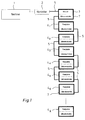
- a series of modules 3, 41 ... 4 x are assigned to a computer 1.
- the modules 3, 41 ... 4 x are connected to each other and to the computer via a bus 51, 52, which is controlled by the computer 1 via a bus controller 2.
- the data bus 51 connects the bus controller 2 and the first module 3 and is used for exchanging information and data of the modules 3, 41 ... 4 x with the computer 1. All combined to form an assembly modules 3 and 4 41 ... x are connected via data cables 52, one data cable connecting two modules in such a way that the modules form the chain shown in FIG. 1.
- a data bus arrangement is provided in each data cable.
- Each module has a functional unit, for example a hard disk unit, a floppy disk drive or another peripheral device, and has a microcontroller, via which the individual modules can exchange information and status signals with one another.
- the first module 3 contains, as a special functional unit, a power supply unit for supplying power to all downstream modules, ie modules belonging to the same module. This relieves the power supply of the computer 1 and ensures a reliable and independent power supply for a limited number of modules. The power supply to the remaining modules is provided by additional lines included in the 52 data cable.
- the data and information lines of the bus 5 1 are also continued in the data cables 5 2.
- the data cable 52 contain additional control lines for exchanging information and control commands between the microcontrollers 7 of the modules 3, 41 ... 4 x .
- the functional units (eg hard drives - Fig. 1) of the modules 41 ... 4 x can access the data bus of the data cable 52 in a known manner via their interfaces.
- the microcontrollers 7 of the modules 3, 4 1 ... 4 x can exchange data serially with one another via selected lines of the data bus if there is no data exchange of the functional units via these lines of the data bus at this time.
- module 3 is designed as a master module. In addition to the power supply unit, it has control devices for configuring the assembly. As will be explained further below, a special control and display panel is provided for this purpose.
- the other modules 41 ... 4 x are designed as slave modules and assigned to the master module.
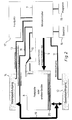
- the structure of the individual modules belonging to the system according to FIG. 1 is shown as an example in FIG. 2.
- the module has a functional unit 8 (for example a hard disk), a microcontroller 7 with an associated ROM 15 for storing programs and an associated information memory 16 (for example an EEPROM) and a front panel 17 with an operating and display panel.
- the module has two interfaces, a data cable input 12 and a data cable output 14, via which it can be connected to other modules using the data cable 5.
- the data bus connected via a data cable 52 to the data cable input 12 is internal via the Data bus 19 to the data cable output 14 and then optionally via a further data cable 52 to the next module.
- the interface 20 of the functional unit 8, for example the hard disk, is coupled to this data bus 19 via a coupling 21.
- a connection port 22 of the microcontroller 7 is connected to the data cable input 12 via status lines 11.
- An output connection port 23 of the microcontroller 7 is connected to the data cable output 14 via status lines 13.
- the microcontroller 7 sets options of the functional unit 8 via lines 9. Such options relate either to the functioning of the functional unit itself (eg write protection, parity) or to the coupling of the functional unit 8 to the data bus 19 (connection of a bus terminating resistor).
- the microcontroller 7 controls the power supply of the functional unit 8 via the line 10.
- the microcontroller 7 can exchange data and control information with the other modules via the status lines 11 and 13 and additionally via the serial data line 18 coupled to the data bus 19. By coupling to the control and display panel 17, the microcontroller 7 can receive signals triggered by operator actions and output signals via the displays.
- Fig. 3 shows the front panels 17 M , 17 S2 , 17 S1 of the modules of an assembly consisting of a master module and two attached slave modules.
- the interconnection and configuration of the modules will be explained on the basis of this exemplary embodiment.
- an input of the master module 3 is connected to the processor 1 via a data bus 5 1.
- slave modules 41 ... 4 x fitted like a tower and data cable inputs 12 and data cable outlets 14 connected in pairs.
- the uppermost slave module 4 x of the tower thus has a free data cable output 14.
- a module is configured in the following way: First, a system group is created on the master module (17 M ) selected by pressing a system key 24. First of all, assume that all modules of an assembly are assigned to the same system group (System 1). After pressing the system key 24, the configuration key 29 (Config) is pressed on the master module (17 M ) and at the same time the selection key 28 (Select) is pressed on the selected slave module (e.g. 17 S1 ). If the selected module (17 S1 ) is not configured, this configuration request is accepted. This is indicated by the key LEDs of the three keys 24a, 28a, 29a (Config 29 and System-1 24 on the master module and Select 28 on the slave module) lighting up. Then the enter key 30 on the master module can be pressed to confirm the assignment. The configuration is confirmed and saved, and the LEDs 28a, 29a, 30a go out.
- the first logical configuration group produced by this method can, for example, form a first logical drive (eg drive C) of the processor 1. This procedure can then be repeated on a second slave module (17 S2 ). A second logical configuration group is formed from the second slave module (17 S2 ) and the master module (17 M ). The next free (second) logical module name (eg drive D) of the first system group is assigned to the second slave module.
- a first logical drive eg drive C
- This procedure can then be repeated on a second slave module (17 S2 ).
- a second logical configuration group is formed from the second slave module (17 S2 ) and the master module (17 M ).
- the next free (second) logical module name (eg drive D) of the first system group is assigned to the second slave module.
- a non-erasable memory of the master module 3 stores a serial number (identification code or identifier) which has already been assigned in the manufacturing process and which uniquely identifies the master module.
- the slave modules (automatically) adopt the identifier of the master module. All modules (master and slave modules) of a newly configured module therefore have a common identifier. In normal use, they keep this identifier for the entire remaining period of use.
- the assignment of the slave modules to one of the system groups is indicated by the LED 25 on the associated one Slave module displayed.
- the number assigned to the logical configuration group is indicated by the LEDs 26.
- the assignment of the slave modules and the master module to the configuration groups is stored in the information memories 16 (FIG. 2).
- the configuration once saved is retained even if the module is dismantled and then reassembled in a different physical sequence.
- both slave modules (17 S1 and 17 S2 ) can be assigned to the first configuration group together with the master module (17 M ). If the module is dismantled in this case and only one of the two slave modules (17 S2 ) is later replaced, the incompleteness of the configuration group is shown by the flashing of the assigned LED 26. Slave modules of an incomplete configuration group cannot be activated.
- the configuration groups of an assembly can be selectively assigned to different system groups (System 1, System 2, ). This is done by selecting the corresponding system buttons 24 on the master module (17 M ) before configuring.
- each of the four system groups can have up to six configuration groups (ie, for example, six logical drives: C, D, E, F, G, H).
- one system group can be activated by pressing the corresponding system key 24.
- the active system group is indicated by LEDs 31 on the master module (17 M ).
- the system groups enable simple loading of different operating systems (eg DOS, UNIX, OS / 2) when resetting or warm up the computer 1.
- the first configuration group of a system group is designed as a drive unit with the files necessary for booting the operating system.
- Modules can be coupled with any other master modules. If a slave module configured on a first master module (with a first identifier) is placed elsewhere on another master module (with a different identifier), the module recognizes the slave module as a guest module. This is indicated by the lighting of the guest LED of the LED display 25 of the slave module.
Abstract
Description
Die Erfindung betrifft eine Anordnung und ein Verfahren zur selektiven Kopplung mehrerer Module, insbesondere Plattenlaufwerke und Speichermodule mit einem Prozessor. Unter dem Begriff "Prozessor" wird in der folgenden Beschreibung irgendeine Einrichtung zur Datenverarbeitung, beispielsweise ein Mikroprozessor, ein Computer oder auch ein Großrechner verstanden.The invention relates to an arrangement and a method for the selective coupling of several modules, in particular disk drives and memory modules with a processor. In the following description, the term “processor” is understood to mean any device for data processing, for example a microprocessor, a computer or a mainframe.
Die Mikrocomputertechnik hat in jüngster Zeit eine immer breitere Akzeptanz gefunden. Hier wurden vor allem auf den Gebieten der Bürokommunikation, der Konstruktion, der Informationsübertragung und im industriellen sowie im konstruktiven Bereich immer weitergehende Aufgaben zugewiesen. Existierende Systeme kommen daher bereits nach kurzer Zeit und teilweise lange vor Erreichen ihrer normalen Lebensdauer an die Grenze ihrer funktionellen und kapazitiven Möglichkeit. Etwa erforderliche Speichererweiterungen, der Anschluß zusätzlicher Floppy- oder Festplattenlaufwerke sowie zusätzlicher Eingabe- und Ausgabegeräte, wie Laserdrucker, Laserdisk usw. sind nicht oder nur mit erheblichem Installationsaufwand möglich. Insofern ist der Benutzer bisher vielfach dazu übergegangen, anstelle einer Systemerweiterung einen Systemwechsel auf ein leistungsstärkeres System vorzunehmen. Die hiermit verbundenen Kosten sind erheblich. Die Erweiterung vorhandener Systeme erfordert eine spezielle Anpassung und Einstellung der zusätzlichen Baueinheiten. U.a. muß die an einem Bus letzte Baueinheit mit einem geeigneten Busabschlußwiderstand versehen werden. Daneben gibt es weitere, für jedes zusätzliche Laufwerk einzustellende Betriebsoptionen, wie z.B. einen Schreibschutz. Diese Einstellungen werden beispielsweise durch Jumper oder DIP-Schalter auf einer Leiterkarte der Baueinheit ermöglicht. Bei der Installation jeder neuen Baueinheit, z.B. eines neuen Laufwerks, sind von einem mit dem Gesamtsystem vertrauten Techniker die Betriebsoptionen zu setzen; für den Anwender ist das Setzen von Jumpern oder DIP-Schaltern zu aufwendig, zumal es erhebliche Fachkenntnisse bedingt.Microcomputer technology has recently found increasing acceptance. Here, in the areas of office communication, construction, information transfer, and in the industrial as well as in the construction area, more and more tasks were assigned. Existing systems therefore reach the limits of their functional and capacitive capabilities after a short time and sometimes long before their normal life span is reached. Any necessary memory expansions, the connection of additional floppy or hard drives as well as additional input and output devices such as laser printers, laser disks etc. are not possible or only possible with considerable installation effort. In this respect, the user has often switched to a system change to a more powerful system instead of a system expansion. The associated costs are substantial. The expansion of existing systems requires special adaptation and adjustment of the additional units. Among other things, the last module on a bus must be provided with a suitable bus terminating resistor. There are also other operating options that can be set for each additional drive, such as write protection. These settings are made possible, for example, by jumpers or DIP switches on a circuit board of the module. When installing each new module, eg a new drive, the operating options must be set by a technician familiar with the overall system; setting jumpers or DIP switches is too complex for the user, especially since it requires considerable specialist knowledge.
Durch den Einsatz verschiedener Betriebssysteme, z.B. DOS, UNIX, OS/2 erhöht sich der Bedarf einer flexiblen Anordnung von Festplatten-Baueinheiten des Systems. Ohne aufwendige Änderungen der aktiven Partitionen einer Festplatte kann jeweils nur ein Betriebssystem von einer Festplatte gebootet (d.h. beim System-Reset oder Warmstart geladen) werden. Der Anwender sollte jedoch zur Erleichterung der Kommunikation mit unterschiedlichen Betriebssystemen die Möglichkeit haben, durchaus verschiedene Betriebssysteme in der eigenen Maschine ohne großen Aufwand booten zu können.By using different operating systems, e.g. DOS, UNIX, OS / 2 increases the need for a flexible arrangement of hard disk components of the system. Without extensive changes to the active partitions of a hard disk, only one operating system can be booted from one hard disk at a time (i.e. loaded during a system reset or warm start). However, in order to facilitate communication with different operating systems, the user should be able to boot different operating systems in their own machine without great effort.
Der Erfindung liegt die Aufgabe zugrunde, den Installationsaufwand zu verringern, wenn beliebige aktive und passive Datenverarbeitungsmodule, beispielsweise Plattenlaufwerke, andere Speicher und/oder Peripheriegeräte miteinander und mit wenigstens einem Prozessor zu einer Funktions- oder Baugruppe zusammengefaßt werden oder ihre Konfiguration geändert oder erweitert wird. Insbesondere soll die Neu- und Umkonfiguration einer beliebigen Anzahl von Geräten und Modulen durch den Benutzer selbst erfolgen können.The invention has for its object to reduce the installation effort if any active and passive data processing modules, for example disk drives, other memories and / or peripheral devices are combined with one another and with at least one processor to form a function or assembly or their configuration is changed or expanded. In particular, the user should be able to reconfigure and reconfigure any number of devices and modules.
Gelöst wird diese Aufgabe erfindungsgemäß dadurch, daß jeder der mit dem Prozessor zu koppelnden Module einen Mikrokontroller zur internen Steuerung der Stromversorgung und der Rangierwege (Jumper) und zum Status- und Informationsaustausch mit den gekoppelten Modulen und dem Prozessor und ein mit dem Mikrokontroller gekoppeltes Bedienungs- und Anzeigefeld zur Betätigung und Anzeige durch und für den Benutzer aufweist; daß alle Module einer Baugruppe über ihre Ein- und Ausgänge selektiv in Reihe schaltbar und über einen gemeinsamen Bus mit dem Prozessor koppelbar sind; daß jedem Mikroprozessor Mittel zur Bildung eines Bus-Abschlußwiderstandes zugeordnet sind, die dann wirksam sind, wenn der zugehörige Modul der in der Reihe letzte Modul ist; und daß jedem Modul eine vom Mikrokontroller verwaltete Kennung zur Unterscheidung der Module der Baugruppe, zur Kommunikation der Module untereinander und mit dem Prozessor und zur Zugriffsanforderung auf den Modul zugeordnet ist.This object is achieved according to the invention in that each of the modules to be coupled to the processor has a microcontroller for the internal control of the power supply and the maneuvering paths (jumpers) and for the exchange of status and information with the coupled modules and the processor and an operator control coupled with the microcontroller. and display panel for actuation and display by and for the user; that all modules of a module can be selectively connected in series via their inputs and outputs and can be coupled to the processor via a common bus; that each microprocessor is assigned means for forming a bus terminating resistor, which are effective when the associated module is the last module in the row; and that each module has an identifier managed by the microcontroller to distinguish the modules of the assembly, to communicate the modules with one another and with the processor and is assigned to request access to the module.
Die Erfindung macht es möglich, einem vorhandenen Datenverarbeitungssystem extern einen beliebigen Modul, beispielsweise einen Festplattenmodul oder andere Massenspeicher oder Peripheriegeräte, aber auch ein weiteres Rechnersystem beizustellen und funktionell zu verknüpfen. Diese Verknüpfung mit dem Prozessor kann problemlos vom Anwender selbst konfiguriert und beliebig geändert werden. Der jedem einzelnen Modul zugeordnete Mikrokontroller übernimmt die bisher bei Systemänderungen oder -erweiterungen erforderlichen aufwendigen Rangierfunktionen in der Regel selbsttätig. Insbesondere sorgt der Mikrokontroller des in der Reihe letzten Moduls für den stets erforderlichen Busabschlußwiderstand. Die spezielle Funktion des Massenspeichers oder Peripheriegeräts des Moduls ist für die erfindungsgemäß vorgesehene Einbindung in die Funktions- oder Baugruppe ohne Bedeutung. Der Benutzer ist daher in der Lage, das vorhandene System durch eine oder mehrere Festplatten zu erweitern, von denen ggf. verschiedene Betriebssysteme für den Prozessor durch Kalt- oder Warmstart geladen werden können. Die verschiedenen Massenspeicher können bei der Erfindung auch bei Nichtbenutzung aus der Baugruppe herausgenommen und geschützt vor dem Zugriff unberechtigter Benutzer anderenorts aufbewahrt werden. Später können sie problemlos und unabhängig von der physikalischen Einbau-Reihenfolge wieder in das System eingebunden werden. Ein weiterer Vorteil der Erfindung liegt darin, daß im Falle eines Defekts des Prozessors ein oder mehrere Module aus dem System entnommen und in Verbindung mit einem anderen Rechner ohne komplizierte Anpassung an das neue Systemumfeld weiterbenutzt werden können.The invention makes it possible to provide an existing data processing system externally with any module, for example a hard disk module or other mass storage device or peripheral devices, but also with a further computer system and to link it functionally. This link to the processor can easily be configured by the user and changed as required. The microcontroller assigned to each individual module generally takes over the complex maneuvering functions previously required for system changes or expansions. In particular, the microcontroller of the last module in the row ensures that the bus terminating resistor is always required. The special function of the mass storage device or peripheral device of the module is irrelevant for the integration into the function or assembly provided according to the invention. The user is therefore able to expand the existing system with one or more hard disks, from which, if necessary, different operating systems for the processor can be loaded by cold or warm start. In the invention, the various mass storage devices can also be removed from the assembly when not in use and can be stored elsewhere, protected from access by unauthorized users. Later, they can be integrated back into the system without any problems, regardless of the physical installation sequence. Another advantage of the invention is that in the event of a processor defect, one or more modules can be removed from the system and used in conjunction with another computer without complicated adaptation to the new system environment.
In Weiterbildung der Erfindung ist jedem Mikrokontroller ein vorzugsweise elektrisch programmierbarer Programmspeicher und ein Direktzugriffsspeicher zugeordnet. Durch geeignete Programmierung des Programmspeichers sind die beim Einbau eines Moduls in eine bestehende Baugruppe erforderlichen Maßnahmen beschränkt auf die rein elektrischen Anschlüsse und wenige, per Tastendruck aufrufbare Einbindebefehle.In a development of the invention, a preferably electrically programmable program memory and a direct access memory are assigned to each microcontroller. Appropriate programming of the program memory means that the measures required when installing a module in an existing assembly are limited to the purely electrical connections and a few integration commands that can be called up at the push of a button.
Eine universelle Systemerweiterung wird vor allem dadurch begünstigt, daß ein Netzteilmodul zur Stromversorgung der zu einer Bau- oder Funktionsgruppe zusammengeschalteten Module vorgesehen ist.A universal system expansion is particularly favored by the fact that a power supply module is provided for the power supply of the modules interconnected to form a structural or functional group.
Obwohl sich die Erfindung grundsätzlich auch in Verbindung mit mehreren intelligenten Systemen verwenden läßt, die ohne besondere Priorität auf den Datenbus zum Prozessor zugreifen können, ist bei einem bevorzugten Ausführungsbeispiel der Erfindung vorgesehen, daß einer der zu einer Baugruppe zusammengeschalteten Module als Master ausgebildet und geeignet ist, den als Slave-Modulen organisierten anderen Baugruppenmodulen Kennungen zuzuweisen und alle Baugruppenmodule zu konfigurieren.Although the invention can in principle also be used in connection with several intelligent systems which can access the data bus to the processor without special priority, it is provided in a preferred embodiment of the invention that one of the modules connected to an assembly is designed and suitable as a master to assign identifiers to the other module modules organized as slave modules and to configure all module modules.
Das Verfahren zur selektiven Kopplung mehrerer Module mit einem Prozessor zeichnet sich erfindungsgemäß dadurch aus, daß ein Eingang eines ersten Moduls über einen Datenbus mit dem Prozessor verbunden wird; mehrere weitere Module in Reihe an den Ausgang des ersten Moduls angeschaltet werden, wobei die Verbindung von Modul zu Modul jeweils über ein Datenkabel hergestellt wird und der Datenbus des in der Reihe letzten angekoppelten Moduls mit einem Abschlußwiderstand abgeschlossen wird; und die gekoppelten Module konfiguriert werden, indem: mindestens einer der weiteren Module durch gleichzeitiges Betätigen jeweils einer Selektionstaste an dem mindestens einen weiteren Modul und einer Konfigurations-Taste am ersten Modul selektiert und mit dem ersten Modul zu einer ersten logischen Konfigurationsgruppe gekoppelt und die selektive Kopplung in der Konfigurationsgruppe durch Betätigen einer Enter-Taste am ersten Modul bestätigt wird.The method for the selective coupling of several modules with one processor is characterized according to the invention in that an input of a first module is connected to the processor via a data bus; several further modules are connected in series to the output of the first module, the connection from module to module being established in each case via a data cable and the data bus of the last module connected in the series being terminated with a terminating resistor; and the coupled modules are configured in that: at least one of the further modules is selected by simultaneously pressing a selection button on the at least one further module and a configuration button on the first module and is coupled to the first module to form a first logical configuration group and the selective coupling is confirmed in the configuration group by pressing an Enter key on the first module.
Weitere Einzelheiten und vorteilhafte Weiterbildungen der Erfindung sind in den Unteransprüchen gekennzeichnet.Further details and advantageous developments of the invention are characterized in the subclaims.
Im folgenden wird die Erfindung anhand eines in der Zeichnung dargestellten Ausführungsbeispiels näher erläutert. In der Zeichnung zeigen:
- Fig. 1
- ein Blockschaltbild eines Ausführungsbeispiels der Erfindung, bei dem mehrere Festplattenmodule, die über einen Netzteil- und Mastermodul mit Strom versorgt werden, als variierbare Baugruppe an einen Prozessor angeschaltet sind;
- Fig. 2
- ein Blockschaltbild der wesentlichen Komponenten eines Ausführungsbeispiels eines der in Fig. 1 gezeigten Module; und
- Fig. 3
- die Frontplatten mit den Bedienungs- und Anzeigefeldern von drei Modulen in dem Ausführungsbeispiel gemäß Fig. 1.
- Fig. 1
- a block diagram of an embodiment of the invention, in which a plurality of hard disk modules, which are supplied with power via a power pack and master module, are connected to a processor as a variable assembly;
- Fig. 2
- a block diagram of the essential components of an embodiment of one of the modules shown in Fig. 1; and
- Fig. 3
- the front panels with the control and display panels of three modules in the embodiment of FIG. 1st
In dem in Fig. 1 dargestellten Ausführungsbeispiel sind einem Rechner 1 eine Reihe von Modulen 3, 4₁ ... 4x zugeordnet. Die Module 3, 4₁ ... 4x sind untereinander und mit dem Rechner über einen Bus 5₁, 5₂ verbunden, der vom Rechner 1 über einen Bus-Kontroller 2 angesteuert wird. Der Datenbus 5₁ verbindet den Bus-Kontroller 2 und den ersten Modul 3 und dient zum Informations- und Datenaustausch der Module 3, 4₁ ... 4x mit dem Rechner 1. Alle zu einer Baugruppe vereinigten Module 3 und 4₁ ... 4x sind über Datenkabel 5₂ verbunden, wobei jeweils ein Datenkabel zwei Module derart verbindet, daß die Module die in Fig. 1 dargestellte Kette bilden. Wie weiter unten noch erläutert werden wird, ist in jedem Datenkabel eine Datenbusanordnung vorgesehen.In the embodiment shown in Fig. 1, a series of
Jeder Modul weist eine Funktionseinheit, beispielsweise eine Festplatteneinheit, ein Floppy-Disk-Laufwerk oder ein anderes Peripheriegerät, auf und hat einen Mikrokontroller, über den die einzelnen Module untereinander Informationen und Zustandssignale austauschen können. Der erste Modul 3 enthält als besondere Funktionseinheit ein Netzteil zur Stromversorgung aller nachgeschalteten, d.h. zur selben Baugruppe gehörigen Module. Dadurch wird das Netzteil des Rechners 1 entlastet und eine zuverlässige und unabhängige Stromversorgung für eine begrenzte Anzahl von Modulen sichergestellt. Die Stromversorgung der restlichen Module erfolgt durch zusätzliche, im Datenkabel 5₂ enthaltene Leitungen.Each module has a functional unit, for example a hard disk unit, a floppy disk drive or another peripheral device, and has a microcontroller, via which the individual modules can exchange information and status signals with one another. The
Die Daten- und Informationsleitungen des Busses 5₁ sind auch in den Datenkabeln 5₂ weitergeführt. Die Datenkabel 5₂ enthalten zusätzliche Steuerleitungen zum Austausch von Informationen und Steuerbefehlen zwischen den Mikrokontrollern 7 der Module 3, 4₁ ... 4x. Die Funktionseinheiten (z.B. Festplatten - Fig. 1) der Module 4₁ ... 4x können in bekannter Weise über ihre Schnittstellen auf den Datenbus der Datenkabel 5₂ zugreifen. Zusätzlich können die Mikrokontroller 7 der Module 3, 4₁ ... 4x über ausgewählte Leitungen des Datenbus untereinander seriell Daten austauschen, wenn zu diesem Zeitpunkt kein Datenaustausch der Funktionseinheiten über diese Leitungen des Datenbus stattfindet.The data and information lines of the
Im bevorzugten Ausführungsbeispiel ist der Modul 3 als Master-Modul ausgebildet. Er weist neben dem Netzteil Steuereinrichtungen zum Konfigurieren der Baugruppe auf. Wie weiter unten noch erläutert werden wird, ist zu diesem Zweck ein besonderes Bedienungs- und Anzeigefeld vorgesehen. Die anderen Module 4₁ ... 4x sind als Slave-Module ausgebildet und dem Master-Modul zugeordnet.In the preferred exemplary embodiment,
Der Aufbau der zu dem System gemäß Fig. 1 gehörigen Einzelmodule ist als Beispiel in Fig. 2 gezeigt. Der Modul weist eine Funktionseinheit 8 (beispielsweise eine Festplatte), einen Mikrokontroller 7 mit zugeordnetem ROM 15 zur Speicherung von Programmen und zugeordnetem Informationsspeicher 16 (beispielsweise einem EEPROM) sowie eine Frontplatte 17 mit Bedienungs- und Anzeigefeld auf. Der Modul besitzt zwei Schnittstellen, einen Datenkabel-Eingang 12 und einen Datenkabel-Ausgang 14, über die er mit Hilfe der Datenkabel 5 mit anderen Modulen verbunden werden kann. Der über ein Datenkabel 5₂ am Datenkabel-Eingang 12 anliegende Datenbus wird intern über den Datenbus 19 zum Datenkabel-Ausgang 14 und dann ggf. über ein weiteres Datenkabel 5₂ zum nächsten Modul geführt. An diesen Datenbus 19 ist über eine Ankopplung 21 die Schnittstelle 20 der Funktionseinheit 8, beispielsweise der Festplatte, angekoppelt. Ein Anschlußport 22 des Mikrokontrollers 7 ist über Statusleitungen 11 mit dem Datenkabel-Eingang 12 verbunden. Ein Ausgangs-Anschlußport 23 des Mikrokontrollers 7 ist über Statusleitungen 13 mit dem Datenkabel-Ausgang 14 verbunden. Über Leitungen 9 stellt der Mikrokontroller 7 Optionen der Funktionseinheit 8 ein. Solche Optionen betreffen entweder die Arbeitsweise der Funktionseinheit selbst (z.B. Schreibschutz, Parität) oder die Ankopplung der Funktionseinheit 8 an den Datenbus 19 (Zuschaltung eines Busabschlußwiderstandes). Ferner steuert der Mikrokontroller 7 die Stromversorgung der Funktionseinheit 8 über die Leitung 10. Der Mikrokontroller 7 kann über die Statusleitungen 11 und 13 sowie zusätzlich über die an den Datenbus 19 angekoppelte serielle Datenleitung 18 mit den anderen Modulen Daten und Steuerinformationen austauschen. Durch die Kopplung mit dem Bedienungs- und Anzeigefeld 17 kann der Mikrokontroller 7 durch Bedieneraktionen ausgelöste Signale empfangen und über die Anzeigen Signale ausgeben.The structure of the individual modules belonging to the system according to FIG. 1 is shown as an example in FIG. 2. The module has a functional unit 8 (for example a hard disk), a
Fig. 3 zeigt die Frontplatten 17M, 17S2, 17S1 der Module einer Baugruppe aus einem Master-Modul und zwei aufgesetzten Slave-Modulen. Anhand dieses Ausführungsbeispiels soll die Zusammenschaltung und Konfigurierung der Module erläutert werden. Zunächst wird ein Eingang des Master-Moduls 3 über einen Datenbus 5₁ mit dem Prozessor 1 verbunden. Auf dem Master-Modul 3 werden in beliebiger Reihenfolge die ihm zuzuordnenden Slave-Module 4₁ ... 4x turmartig aufgesetzt und über Datenkabel-Eingänge 12 und Datenkabel-Ausgänge 14 paarweise verbunden. Der oberste Slave-Modul 4x des Turmes weist somit einen freien Datenkabel-Ausgang 14 auf.Fig. 3 shows the
Das Konfigurieren einer Baugruppe geschieht in folgender Weise: Zuerst wird am Master-Modul (17M) eine Systemgruppe durch Drücken einer System-Taste 24 ausgewählt. Zunächst sei angenommen, daß alle Module einer Baugruppe derselben Systemgruppe (System 1) zugeordnet sind. Nach dem Drücken der System-Taste 24 wird am Master-Modul (17M) die Konfigurations-Taste 29 (Config) und gleichzeitig am selektierten Slave-Modul (z.B. 17S1) die Selektions-Taste 28 (Select) gedrückt. Wenn der selektierte Modul (17S1) unkonfiguriert ist, wird diese Konfigurationsanforderung akzeptiert. Dies wird dadurch angezeigt, daß die Tasten-LED der drei Tasten 24a, 28a, 29a (Config 29 und System-1 24 am Master-Modul und Select 28 am Slave-Modul) aufleuchten. Dann kann zur Bestätigung der Zuordnung die Enter-Taste 30 am Master-Modul gedrückt werden. Die Konfiguration wird damit bestätigt und abgespeichert, und die LED's 28a, 29a, 30a erlöschen.A module is configured in the following way: First, a system group is created on the master module (17 M ) selected by pressing a system key 24. First of all, assume that all modules of an assembly are assigned to the same system group (System 1). After pressing the system key 24, the configuration key 29 (Config) is pressed on the master module (17 M ) and at the same time the selection key 28 (Select) is pressed on the selected slave module (e.g. 17 S1 ). If the selected module (17 S1 ) is not configured, this configuration request is accepted. This is indicated by the key LEDs of the three keys 24a, 28a, 29a (Config 29 and System-1 24 on the master module and
Die durch dieses Verfahren hergestellte erste logische Konfigurationsgruppe kann beispielsweise ein erstes logisches Laufwerk (z.B. Laufwerk C) des Prozessors 1 bilden. Anschließend kann dieses Verfahren an einem zweiten Slave-Modul (17S2) wiederholt werden. Dabei wird eine zweite logische Konfigurationsgruppe aus dem zweiten Slave-Modul (17S2) und dem Master-Modul (17M) gebildet. Dem zweiten Slave-Modul wird die nächste freie (zweite) logische Modul-Bezeichnung (z.B. Laufwerk D) der ersten Systemgruppe zugeordnet.The first logical configuration group produced by this method can, for example, form a first logical drive (eg drive C) of the
In einem nichtlöschbaren Speicher des Master-Moduls 3 ist eine bereits im Herstellungsprozeß vergebene Seriennummer (Identifikationscode oder Kennung) gespeichert, die den Master-Modul eindeutig identifiziert. Beim Konfigurieren übernehmen die Slave-Module (automatisch) die Kennung des Master-Moduls. Alle Module (Master- und Slave-Module) einer neu konfigurierten Baugruppe besitzen somit eine gemeinsame Kennung. Im normalen Anwendungsfall behalten sie diese Kennung für die gesamte weitere Einsatzzeit.A non-erasable memory of the
Die Zuordnung der Slave-Module zu einer der Systemgruppen (im Beispiel Systemgruppe 1) wird durch die LED 25 am zugehörigen Slave-Modul angezeigt. Die der logischen Konfigurationsgruppe zugeordnete Nummer wird durch die LED's 26 angezeigt.The assignment of the slave modules to one of the system groups (in the example system group 1) is indicated by the
Die Zuordnung der Slave-Module und des Master-Moduls zu den Konfigurationsgruppen wird in den Informationsspeichern 16 (Fig. 2) gespeichert. Die einmal gespeicherte Konfiguration bleibt auch dann erhalten, wenn die Baugruppe demontiert und anschließend in einer anderen physikalischen Reihenfolge wieder zusammengesetzt wird.The assignment of the slave modules and the master module to the configuration groups is stored in the information memories 16 (FIG. 2). The configuration once saved is retained even if the module is dismantled and then reassembled in a different physical sequence.
Es ist auch möglich, mehrere Slave-Module beim Konfigurieren gleichzeitig anzuwählen. Dadurch erscheinen die Slave-Module dem Rechner 1 als eine einzige Systemeinheit der Systemgruppe, z.B. als ein einziges logisches Laufwerk mit der akkumulierten Kapazität der Laufwerkseinheiten der Slave-Module. Im dargestellten Ausführungsbeispiel nach Fig. 3 können demnach beide Slave-Module (17S1 und 17S2) gemeinsam mit dem Master-Modul (17M) der ersten Konfigurationsgruppe zugeordnet werden. Wird in diesem Fall die Baugruppe demontiert und später nur einer der beiden Slave-Module (17S2) wieder aufgesetzt, so zeigt sich die Unvollständigkeit der Konfigurationsgruppe am Blinken der zugeordneten LED 26. Slave-Module einer unvollständigen Konfigurationsgruppe können nicht aktiviert werden.It is also possible to select several slave modules at the same time during configuration. As a result, the slave modules appear to the
Die Konfigurationsgruppen einer Baugruppe (eines Turms) können selektiv verschiedenen Systemgruppen (System 1, System 2, ...) zugeordnet werden. Dies geschieht durch Anwahl der entsprechenden Systemtasten 24 am Master-Modul (17M) vor dem Konfigurieren. Im bevorzugten Ausführungsbeispiel kann jede der vier Systemgruppen bis zu sechs Konfigurationsgruppen (d.h. beispielsweise sechs logische Laufwerke: C, D, E, F, G, H) aufweisen. Während des Betriebs der Baugruppe (des Turms) ist jeweils eine Systemgruppe durch Drücken der entsprechenden Systemtaste 24 aktivierbar. Die aktive Systemgruppe wird durch die LED's 31 am Master-Modul (17M) angezeigt.The configuration groups of an assembly (of a tower) can be selectively assigned to different system groups (
Die Systemgruppen ermöglichen ein einfaches Laden unterschiedlicher Betriebssysteme (z.B. DOS, UNIX, OS/2) beim Rücksetzen oder Warmstarten des Rechners 1. Dazu ist die jeweils erste Konfigurationsgruppe einer Systemgruppe als Laufwerkseinheit mit den zum Booten des Betriebssystems notwendigen Dateien ausgebildet.The system groups enable simple loading of different operating systems (eg DOS, UNIX, OS / 2) when resetting or warm up the
Module können mit beliebigen anderen Master-Modulen gekoppelt werden. Wird ein auf einem ersten Master-Modul (mit einer ersten Kennung) konfigurierter Slave-Modul anderenorts auf einen anderen Master-Modul (mit einer anderen Kennung) aufgesetzt, so erkennt die Baugruppe den Slave-Modul als Gast-Modul. Dies wird durch Aufleuchten der Gast-LED der LED-Anzeige 25 des Slave-Moduls angezeigt.Modules can be coupled with any other master modules. If a slave module configured on a first master module (with a first identifier) is placed elsewhere on another master module (with a different identifier), the module recognizes the slave module as a guest module. This is indicated by the lighting of the guest LED of the
Zur Erhöhung der Betriebssicherheit der Tastensteuerung sind alle o.g. Tasten 24, 27-30 nichtrastend ausgebildet und mit einer LED-Anzeige 24a, 27a-30a in der Taste versehen. Die Tasten werden durch die Mikrokontroller 7 abgefragt, die mit Hilfe der im Programmspeicher 15 gespeicherten Programme unsinnige und fehlerhafte Tastenkombinationen erkennen und mit Hilfe einer zeitlichen Steuerung ("time-out-Überprüfung") eine richtige Reihenfolge des Drückens der Tastenkombinationen überprüfen. Konfigurationsänderungen erfordern stets das gleichzeitige Drücken mehrerer Tasten und eine anschließende Bestätigung durch die Enter-Taste 30 am Master-Modul.To increase the operational safety of the button control, all of the above Keys 24, 27-30 non-latching and provided with an LED display 24a, 27a-30a in the key. The keys are queried by the
Claims (13)
dadurch gekennzeichnet,
daß jeder der mit dem Prozessor (1) zu koppelnden Module (3, 4₁, 4₂..4x) einen Mikrokontroller (7) zur internen Steuerung der Stromversorgung (10) und der Rangierwege und zum Status- und Informationsaustausch (11, 13, 18) mit gekoppelten Modulen und mit dem Prozessor und ein mit dem Mikrokontroller (7) gekoppeltes Bedienungs- und Anzeigefeld (17) zur Betätigung und Anzeige durch und für den Benutzer aufweist;
daß alle Module einer Baugruppe über ihre Ein- und Ausgänge (12, 14) selektiv in Reihe schaltbar und über einen gemeinsamen Bus (5) mit dem Prozessor (1) koppelbar sind,
daß jedem Mikrokontroller (7) Mittel zur Bildung eines Abschlußwiderstandes zugeordnet sind, die dann wirksam sind, wenn der zugehörige Modul der in der Reihe letzte Modul (4x) ist; und
daß jedem Modul eine vom Mikrokontroller (7) verwaltete Kennung zum Unterscheiden der Module, zur Kommunikation der Module untereinander und mit dem Prozessor und zur Zugriffsanforderung auf den Modul zugeordnet ist.Arrangement for the selective coupling of several modules (3, 4 ... 4 x ), in particular disk drives and memory modules, with at least one processor (1),
characterized,
that each of the modules (3, 4₁, 4₂..4 x ) to be coupled to the processor (1) has a microcontroller (7) for internal control of the power supply (10) and the maneuvering paths and for status and information exchange (11, 13, 18) with coupled modules and with the processor and an operating and display panel (17) coupled to the microcontroller (7) for actuation and display by and for the user;
that all modules of a module can be selectively connected in series via their inputs and outputs (12, 14) and can be coupled to the processor (1) via a common bus (5),
that each microcontroller (7) is assigned means for forming a terminating resistor, which are effective when the associated module is the last module in the row (4 x ); and
that each module is assigned an identifier managed by the microcontroller (7) for distinguishing the modules, for communicating the modules with one another and with the processor and for requesting access to the module.
daß die Module (3, 4₁...4x) über einen von Modul zu Modul und durch die Module hindurch geführten Bus (5; 19, 11, 13) paralleler Leitungen in Reihe geschaltet sind,
daß der Bus paralleler Leitungen einen innerhalb des Moduls ohne Unterbrechung vom Moduleingang (12) zum Modulausgang (14) geführten ersten Bus (Datenbus) (19) und einen zweiten Bus (11, 13) aufweist,
daß jeder Modul über eine Ankopplung (21) an den ersten Bus (19) angebunden ist und auf ihn (19) zugreifen kann,
daß der Mikrokontroller (7) in den zweiten Bus (11, 13) (Steuerbus) zwischen Moduleingang (12) und Modulausgang (14) eingebunden ist und
daß der Mikrokontroller (7) des letzten Moduls (4x) der Reihenschaltung den Bus-Abschlußwiderstand mit der Ankopplung (21) verbindet.Arrangement according to claim 1, characterized in
that the modules (3, 4₁ ... 4 x ) are connected in series via a bus (5; 19, 11, 13) which runs in parallel from module to module and through the modules,
that the bus of parallel lines has a first bus (data bus) (19) and a second bus (11, 13) routed within the module from the module input (12) to the module output (14) without interruption,
that each module via a coupling (21) to the first bus (19) is connected and can access it (19),
that the microcontroller (7) in the second bus (11, 13) (control bus) between module input (12) and module output (14) is integrated and
that the microcontroller (7) of the last module (4 x ) of the series circuit connects the bus terminating resistor to the coupling (21).
dadurch gekennzeichnet, daß
characterized in that
Applications Claiming Priority (2)
| Application Number | Priority Date | Filing Date | Title |
|---|---|---|---|
| DE4033464A DE4033464A1 (en) | 1990-10-20 | 1990-10-20 | ARRANGEMENT FOR SELECTIVE COUPLING OF SEVERAL MODULES TO A PROCESSOR |
| DE4033464 | 1990-10-20 |
Publications (2)
| Publication Number | Publication Date |
|---|---|
| EP0482532A2 true EP0482532A2 (en) | 1992-04-29 |
| EP0482532A3 EP0482532A3 (en) | 1994-08-03 |
Family
ID=6416754
Family Applications (1)
| Application Number | Title | Priority Date | Filing Date |
|---|---|---|---|
| EP91117851A Withdrawn EP0482532A2 (en) | 1990-10-20 | 1991-10-18 | Apparatus for the selective coupling of a plurality of modules with a processor |
Country Status (2)
| Country | Link |
|---|---|
| EP (1) | EP0482532A2 (en) |
| DE (1) | DE4033464A1 (en) |
Cited By (3)
| Publication number | Priority date | Publication date | Assignee | Title |
|---|---|---|---|---|
| US6021465A (en) * | 1995-08-11 | 2000-02-01 | Siemens Nixdorf Informationssysteme Aktiengesellschaft | Arrangement for the connecting peripheral storage devices |
| EP0723223A3 (en) * | 1995-01-18 | 2005-09-21 | Hewlett-Packard Company, A Delaware Corporation | Identifying controller pairs in a dual controller disk array |
| CN112467872A (en) * | 2020-10-21 | 2021-03-09 | 威海锐恩电子股份有限公司 | Electric power energy terminal equipment based on distributed acquisition framework |
Citations (2)
| Publication number | Priority date | Publication date | Assignee | Title |
|---|---|---|---|---|
| US4360870A (en) * | 1980-07-30 | 1982-11-23 | International Business Machines Corporation | Programmable I/O device identification |
| EP0311929A2 (en) * | 1987-10-12 | 1989-04-19 | Olympus Optical Co., Ltd. | Data transfer bus in profile and/or dimension measuring system |
Family Cites Families (6)
| Publication number | Priority date | Publication date | Assignee | Title |
|---|---|---|---|---|
| US4183084A (en) * | 1977-06-06 | 1980-01-08 | Digital Equipment Corporation | Secondary storage facility with serial transfer of control messages |
| FR2561428B1 (en) * | 1984-03-16 | 1986-09-12 | Bull Sa | DISC MEMORY RECORDING METHOD AND DISC MEMORY SYSTEM |
| JPS6278623A (en) * | 1985-10-02 | 1987-04-10 | Toshiba Corp | Magnetic disk device |
| DE3736081A1 (en) * | 1987-10-24 | 1989-05-03 | Licentia Gmbh | Method and device for setting the addresses of subscribers connected to a bus |
| US4870643A (en) * | 1987-11-06 | 1989-09-26 | Micropolis Corporation | Parallel drive array storage system |
| AU630635B2 (en) * | 1988-11-14 | 1992-11-05 | Emc Corporation | Arrayed disk drive system and method |
-
1990
- 1990-10-20 DE DE4033464A patent/DE4033464A1/en not_active Withdrawn
-
1991
- 1991-10-18 EP EP91117851A patent/EP0482532A2/en not_active Withdrawn
Patent Citations (2)
| Publication number | Priority date | Publication date | Assignee | Title |
|---|---|---|---|---|
| US4360870A (en) * | 1980-07-30 | 1982-11-23 | International Business Machines Corporation | Programmable I/O device identification |
| EP0311929A2 (en) * | 1987-10-12 | 1989-04-19 | Olympus Optical Co., Ltd. | Data transfer bus in profile and/or dimension measuring system |
Non-Patent Citations (1)
| Title |
|---|
| IBM TECHNICAL DISCLOSURE BULLETIN. Bd. 29, Nr. 12 , Mai 1987 , NEW YORK US Seiten 5539 - 5540 'Communication adapter.' * |
Cited By (3)
| Publication number | Priority date | Publication date | Assignee | Title |
|---|---|---|---|---|
| EP0723223A3 (en) * | 1995-01-18 | 2005-09-21 | Hewlett-Packard Company, A Delaware Corporation | Identifying controller pairs in a dual controller disk array |
| US6021465A (en) * | 1995-08-11 | 2000-02-01 | Siemens Nixdorf Informationssysteme Aktiengesellschaft | Arrangement for the connecting peripheral storage devices |
| CN112467872A (en) * | 2020-10-21 | 2021-03-09 | 威海锐恩电子股份有限公司 | Electric power energy terminal equipment based on distributed acquisition framework |
Also Published As
| Publication number | Publication date |
|---|---|
| EP0482532A3 (en) | 1994-08-03 |
| DE4033464A1 (en) | 1992-04-23 |
Similar Documents
| Publication | Publication Date | Title |
|---|---|---|
| EP0624832B1 (en) | Electronic control system for modular structured valve station | |
| DE2321260C2 (en) | Multiprocessor data processing system with several reconfigurable data processing groups | |
| DE69818089T2 (en) | INTELLIGENT VEHICLE POWER DISTRIBUTION SYSTEM AND ITS MANUFACTURING METHOD | |
| DE10122228B4 (en) | Job queue control with high availability in an automated data storage library | |
| DE69632406T2 (en) | DATA STORAGE SYSTEM | |
| DE19756564A1 (en) | Communication network with automatic nodal configuration | |
| EP0434986A2 (en) | Method for putting into operation a module connected to an electronic control system | |
| CH637229A5 (en) | METHOD FOR DATA-INDEPENDENT RESERVATION AND RECONNECTING DEVICES IN A DATA-PROCESSING SYSTEM. | |
| WO1998028697A1 (en) | IO- AND MEMORY BUS SYSTEM FOR DFPs AS UNITS WITH TWO- OR MULTI-DIMENSIONALLY PROGRAMMABLE CELL STRUCTURES | |
| DE2404146A1 (en) | DIGITAL STORAGE SYSTEM, BUILT IN AT LEAST THREE HIERARCHY LEVELS | |
| EP1622039B1 (en) | Method and apparatus for assigning addresses to users of a bus system | |
| DE3013070C2 (en) | Circuit arrangement for processing request signals brought in from several peripheral devices within a data processing device | |
| EP0586715B1 (en) | Information transfer method for transferring digital data | |
| EP0109981A1 (en) | Fail-safe data processing equipment | |
| DE102016120081A1 (en) | Method for commissioning and / or maintenance of a fire alarm and / or extinguishing control panel and device therefor | |
| EP0950935B1 (en) | Control device for multiple lamps | |
| DE3048414A1 (en) | "CIRCUIT ARRANGEMENT FOR A DATA PROCESSING SYSTEM" | |
| EP0482532A2 (en) | Apparatus for the selective coupling of a plurality of modules with a processor | |
| DE3238826C2 (en) | ||
| DE2420214A1 (en) | I / O SWITCHING WITH FAILURE COMPENSATION | |
| EP1643679A1 (en) | Configuration of modules in automation systems | |
| EP1072980A2 (en) | Method for addressing users in a bus system | |
| WO1993025966A1 (en) | Computer system | |
| DE3942690C2 (en) | Connector | |
| WO2002086634A2 (en) | Method and system for the continuous use of input and output addresses in a modular control system |
Legal Events
| Date | Code | Title | Description |
|---|---|---|---|
| PUAI | Public reference made under article 153(3) epc to a published international application that has entered the european phase |
Free format text: ORIGINAL CODE: 0009012 |
|
| AK | Designated contracting states |
Kind code of ref document: A2 Designated state(s): AT BE CH DE ES FR GB IT LI NL SE |
|
| PUAL | Search report despatched |
Free format text: ORIGINAL CODE: 0009013 |
|
| AK | Designated contracting states |
Kind code of ref document: A3 Designated state(s): AT BE CH DE ES FR GB IT LI NL SE |
|
| STAA | Information on the status of an ep patent application or granted ep patent |
Free format text: STATUS: THE APPLICATION IS DEEMED TO BE WITHDRAWN |
|
| 18D | Application deemed to be withdrawn |
Effective date: 19950204 |