EP0482805B1 - Two-page automotive virtual image display - Google Patents
Two-page automotive virtual image display Download PDFInfo
- Publication number
- EP0482805B1 EP0482805B1 EP91309428A EP91309428A EP0482805B1 EP 0482805 B1 EP0482805 B1 EP 0482805B1 EP 91309428 A EP91309428 A EP 91309428A EP 91309428 A EP91309428 A EP 91309428A EP 0482805 B1 EP0482805 B1 EP 0482805B1
- Authority
- EP
- European Patent Office
- Prior art keywords
- image
- virtual image
- imaging illumination
- image source
- axis
- Prior art date
- Legal status (The legal status is an assumption and is not a legal conclusion. Google has not performed a legal analysis and makes no representation as to the accuracy of the status listed.)
- Expired - Lifetime
Links
- 230000003287 optical effect Effects 0.000 claims description 56
- 238000005286 illumination Methods 0.000 claims description 35
- 238000003384 imaging method Methods 0.000 claims description 28
- 230000009977 dual effect Effects 0.000 description 17
- 238000013461 design Methods 0.000 description 7
- 230000008901 benefit Effects 0.000 description 4
- 230000001681 protective effect Effects 0.000 description 3
- 230000009467 reduction Effects 0.000 description 3
- 238000013459 approach Methods 0.000 description 2
- 238000004590 computer program Methods 0.000 description 2
- 239000004973 liquid crystal related substance Substances 0.000 description 2
- 238000012423 maintenance Methods 0.000 description 2
- 238000001228 spectrum Methods 0.000 description 2
- 230000004075 alteration Effects 0.000 description 1
- 238000004458 analytical method Methods 0.000 description 1
- 230000005540 biological transmission Effects 0.000 description 1
- 230000008859 change Effects 0.000 description 1
- 239000011248 coating agent Substances 0.000 description 1
- 238000000576 coating method Methods 0.000 description 1
- 230000003247 decreasing effect Effects 0.000 description 1
- 238000012938 design process Methods 0.000 description 1
- 238000005516 engineering process Methods 0.000 description 1
- 230000007613 environmental effect Effects 0.000 description 1
- 239000000446 fuel Substances 0.000 description 1
- 210000003128 head Anatomy 0.000 description 1
- 238000002347 injection Methods 0.000 description 1
- 239000007924 injection Substances 0.000 description 1
- 238000005304 joining Methods 0.000 description 1
- 238000004519 manufacturing process Methods 0.000 description 1
- 238000012986 modification Methods 0.000 description 1
- 230000004048 modification Effects 0.000 description 1
- 239000002991 molded plastic Substances 0.000 description 1
- 238000000926 separation method Methods 0.000 description 1
- 238000004513 sizing Methods 0.000 description 1
- 239000000243 solution Substances 0.000 description 1
- 239000000126 substance Substances 0.000 description 1
- 239000000758 substrate Substances 0.000 description 1
- 230000000007 visual effect Effects 0.000 description 1
Images


Classifications
-
- G—PHYSICS
- G02—OPTICS
- G02B—OPTICAL ELEMENTS, SYSTEMS OR APPARATUS
- G02B27/00—Optical systems or apparatus not provided for by any of the groups G02B1/00 - G02B26/00, G02B30/00
-
- G—PHYSICS
- G02—OPTICS
- G02B—OPTICAL ELEMENTS, SYSTEMS OR APPARATUS
- G02B27/00—Optical systems or apparatus not provided for by any of the groups G02B1/00 - G02B26/00, G02B30/00
- G02B27/01—Head-up displays
- G02B27/0101—Head-up displays characterised by optical features
-
- B60K35/215—
-
- B60K2360/334—
-
- G—PHYSICS
- G02—OPTICS
- G02B—OPTICAL ELEMENTS, SYSTEMS OR APPARATUS
- G02B27/00—Optical systems or apparatus not provided for by any of the groups G02B1/00 - G02B26/00, G02B30/00
- G02B27/01—Head-up displays
- G02B27/0149—Head-up displays characterised by mechanical features
- G02B2027/0165—Head-up displays characterised by mechanical features associated with a head-down display
Definitions
- the disclosed invention is directed generally to virtual image displays, and is more particularly directed to a virtual image display for vehicle instrumentation which provides a plurality of different displays in the same location.
- WO 89/02611 discloses a virtual image display for a vehicle that has the features of the pre-characterising part of Claim 1.
- Vehicle instrumentation commonly includes primary instrumentation which is located in front of the operator, for example, in a traditional instrument cluster positioned in front of the steering wheel.
- Secondary instruments including, for example, radio control status indicators, environment control status indicators, trip computer controls and indicators, maintenance annunciators, and message indicators, are commonly located in a center-mounted panel.
- the displays of the secondary instruments are being implemented with vacuum fluorescent displays (VFDs) or cathode ray tubes (CRTs).
- VFDs vacuum fluorescent displays
- CRTs cathode ray tubes
- a consideration with the separation of primary and secondary instruments includes the required head and eye motion for reading the secondary instruments, producing at least a nuisance if not a potential hazard.
- Another advantage would be to provide a vehicle instrumentation display that permits the selective display of different types of information at the same position ahead of the driver.
- a virtual image display for vehicles that includes a first image source for providing first imaging illumination, second image source for providing second imaging illumination, a combiner responsive to the first and second imaging illumination for providing combiner imaging illumination, a negative power aspheric off-axis mirror responsive to the combiner imaging illumination for providing diverging reflected imaging illumination, and a positive power aspheric off-axis mirror responsive to the diverging imaging illumination for providing converging reflected imaging illumination that produces a virtual image of the image sources observable by the vehicle operator.
- the first and second image sources can be selectively illuminated so as to display only one image source at any given time, or they can he selectively illuminated so that the first image source provides certain components of the virtual image while the second image source provides other components of the virtual image.
- the virtual image display can be located, for example, above the vehicle steering column and ahead of the steering wheel, for example, generally in the region traditionally occupied by an instrument panel.
- the display system includes a first image source 11 and a planar combiner 13 for reflecting at least a portion of the imaging illumination from the first image source 11.
- a second image source 12 provides second imaging illumination to the planar combiner 13 which transmits at least a portion of the second imaging illumination.
- the reflected first imaging illumination and the transmitted second imaging illumination are directed to an off-axis convex negative power mirror 15 which provides for diverging reflected illumination.
- the mirror 15 is characterized as having negative power since it would produce image reduction if viewed directly, and is further characterized as providing for diverging reflection since parallel rays incident thereon would diverge upon reflection.
- the illumination from the negative power mirror 15 is incident upon an off-axis concave positive power mirror 17 which provides for converging reflected illumination.
- the mirror 17 is characterized as having positive power since it provides for image magnification, and is further characterized as providing for converging reflection since parallel rays incident thereon would converge upon reflection.
- the illumination reflected by the positive power mirror 17 passes through a curved protective window 19 to the observer.
- the curved protective window 19 is more particularly, as viewed from outside the display system, a concave portion of an elliptically shaped cylinder that is configured so that the reflections therefrom that can be seen by the observer will be limited to reflections of a darkened light trap located above the protective window.
- the first image source 11 comprises (a) a group of electromechanical gauges for indicating speed, engine RPMs, oil temperature, oil pressure, and fuel level, for example; and (b) annunciator lights for turn-signals, high beam, and emergency engine indications, for example.
- FIG. 2 sets forth a schematic illustration of an example of the display that can be produced by the first image source.
- the second image source comprises a large alpha-numeric display, such as a VFD or a liquid crystal display (LCD), for example, for providing alphanumeric information such as messages, maintenance instructions, and environmental status and settings.
- FIG. 3 sets forth a schematic illustration of an example of the display that can be produced by the second image source.
- the combiner 13 comprises a half-silvered mirror or a dielectric dichroic mirror, for example.
- the dichroic mirror is configured to reflect illumination in the yellow/orange/red region of the spectrum and to transmit illumination in the blue/green region.
- the electromechanical gauges of the first image source would be illuminated with appropriately filtered incandescent bulbs, and the annunciator lights would be configured to produce the appropriate light for reflection by the dichroic mirror.
- the VFD is self luminous and its output would be in the appropriate spectrum range for transmission by the dichroic mirror.
- the first and second image sources can be displayed independently to provide a two-page display wherein the source to be displayed would illuminated while the other source would not be illuminated. Also, portions of each display can be selectively illuminated so as to produce a virtual image that comprises the illuminated portions from each image source.
- the speedometer in the first image source can be the only first image source component illuminated, and selected portions of the second image source are illuminated to produce virtual image components around the speedometer virtual image.
- the negative and positive power mirrors 15 and 17 have aspheric, non-rotationally symmetrical reflecting surfaces, and can comprise, for example, injection molded or cast molded plastic substrates having requisite aspheric surfaces which are coated with a metallic reflective coating.
- the aspheric elements 15, 17 have respective optical axes OA1, OA2 which are the optical axes defined by the base radii of the respective reflecting surfaces prior to being aspherically deformed.
- the optical axes pass through the optical axis points P1, P2 which are utilized as the origins of the respective coordinate systems utilized to define the aspheric deformation of the respective surfaces.
- the optical axis points P1, P2 and the axes passing therethrough remain fixed while the surrounding areas are aspherically deformed.
- the optical axis OA1 bisects the incidence and reflection portions of a central axis CA which is defined by the ray that joins the image source center with the image center and passes through the optical axis points P1, P2.
- the optical axis OA2 also bisects the incidence and reflection portions of the central axis CA.
- the aspheric elements are off-axis since the central axis CA is not colinear with the optical axes, and the image source and image do not lie on the optical axes of the aspheric elements including any reflective folds thereof.
- the central axis CA further defines an optical path travelled by the imaging illumination from the image source to the eyes of the vehicle operator, and as discussed further herein such optical path has a distance that is greater than the effective viewing distance of the virtual image (i.e., the distance at which the operator's eyes focus in order to view the virtual image).
- the negative mirror 15 is the smaller mirror and is positioned relative to the larger positive mirror 17 pursuant to relatively simple optical formulae (e.g., as in a Cassegrain telescope) to achieve a reasonable magnification range for a magnified virtual image without necessitating a change in the sizes of the image source 11, 12 or the virtual image range (i.e., the effective distance at which the viewer's eyes focus to see the virtual image).
- the virtual image range is in the range of about 4 to 12 feet, which is greater than the typical distance between the driver's eyes and direct view instrumentation in an instrument panel.
- a negative mirror and a positive mirror provides for appropriate magnification, virtual image range, field of view, and optical performance (i.e., reduction of distortion and disparity), while maintaining an optical system length (i.e., the distance between the image source and the mirror optically closest to the nominal eye position) that is more compact than a single, positive mirror system having comparable parameters.
- an optical system length i.e., the distance between the image source and the mirror optically closest to the nominal eye position
- the compactness of the dual mirror system results from the reverse telephoto arrangement of the negative and positive mirrors, which provides for an increased working focal length without a significant increase in the system length.
- the working focal length is the distance from the image source to the "first principle plane" which, as is well known, is located at the position at which a single lens or mirror would be located to produce a single lens or mirror optical system having substantially the same parameters.
- the first principle plane for the dual mirror system is located between the nominal eye position and the mirror optically closest thereto, while the first principle plane for a single positive mirror system is located at the mirror. In other words, the first principle plane for the dual mirror system is not constrained to be at the physical location of one of the optical elements.
- FIGS. 4 and 5 which essentially are unfolded versions of a single lens system and a dual mirror system, and are easier to understand.
- the pertinent optical parameters are as follows: Range (R) : The distance from the nominal eye position to the virtual image. Eye Relief (L) : The distance from the nominal eye position to the first lens surface. Eye Box (Y) : The diameter of the space about the nominal eye position where the virtual image can be viewed without any vignetting.
- Field of View (FOV) The angular substance of the virtual image as viewed from the nominal eye position.
- System Length (Z) The distance between the lens closest to the eye and the image source.
- Back Focus (B) The distance from the image source to the lens nearest the image source.
- Working Focal Length (F) The distance from the image source to the first principle plane of the optical system.
- Working Diameter (D) The diameter of the first principle plane.
- Working F-Number (F/#) The ratio of the working focal length and the working diameter (i.e., F/D).
- Image Source Size (H) The height (in the vertical plane) of the image source.
- Virtual Image Size (H') The height (in the vertical plane) of the virtual image.
- the optical performance of the respective single and dual lens systems (i.e., the reduction of distortion and disparity) is directly related to the working F/#.
- performance deteriorates as the working F/# is decreased. Therefore, for a given performance specification, the working F/# is generally fixed. Also, it may be desirable to make the system length Z as short as practicable to minimize the optical package.
- the working diameter D is simply the diameter of the lens.
- the working diameter is defined by Equation 1. Since the working F/# is minimized and fixed for
- a single lens system provides adequate performance if the image sources can be arbitrarily sized to match the image source size requirements discussed above. Such sizing can be achieved if the image sources comprise liquid crystal displays (LCDs) or VFDs wherein the size of the graphics can be readily changed to be sufficiently small.
- LCDs liquid crystal displays
- VFDs vacuum crystal displays
- electromechanical gauges cannot be miniaturized smaller than a certain size, for example, about one inch in diameter. Given the size constraint for an analog image source, the foregoing equations will need to be applied in reverse starting with a given image source size.
- both the working focal length and the FOV will have to increase for a constant working F/#. If the FOV must remain constant, then the working diameter will also be constant, and the only way to use a larger image source size will be to increase the F/#. This will also increase the working focal length (even greater than in the case where the FOV can be increased).
- the system length must be increased for a single lens system if an analog gauge is used as the image source. A longer system means a longer box and an overall increase in the optical package size.
- the dual lens system of FIG. 5 which is the unfolded version of the disclosed dual mirror system, and functions as a reverse telephoto arrangement that provides for an increased working focal length without an increase in the system length.
- the range is set to infinity as above relative to the single lens system.
- the focal length of the two lenses are f1 and f2, with f1 being a positive focal length and f2 a negative focal length.
- the focal length actually exceeds the system length.
- the focal length is substantially independent of the back focus and the system length.
- Equation 8 If the image source size is changed while keeping the working F/# and the field of view FOV constant, the working focal length is set by Equation 8; the working diameter D is set by the working F/#; and L1 is set by Equation 7. Equation 6 can then be solved for the quantity (x + B) which is the system length.
- the working F/# should not be less than 2.0.
- the image source size must be 0.394 inch.
- the FOV can be changed to reduce the focal length.
- (D)(F/#) for the focal length F in Equation 2
- H (2 F/# tan(FOV/2))[2 L tan(FOV/2)+Y]
- the dual lens approach will now be analyzed for an image source size of one inch.
- the working focal length is 19.094 inches for a 3° FOV.
- L1 is then equal to 12.42 inches.
- the focal lengths of each lens can vary relative to one another, but one solution from Equation 5 is that f1 is 7.568 inches and f2 is -7.568 inches. Since the size of f1 is the same as the working diameter of the single lens system of 3.757, the F/# of f1 is 2.014.
- the dual lens system provided for a system length that is comparable to a single lens system having a smaller image source size. It is also pointed out that since the working F/#'s of the individual lenses in the dual lens system are not too fast, the optical performance will be better than the single lens approach since there are two lenses to optimize.
- the foregoing analysis of the dual lens system could be utilized to arrive at a first-order design, which would be followed by utilizing an optical design computer program with the spherical mirror versions of the first-order design.
- the nominal spherical surfaces are deformed to meet the desired criteria of minimizing distortions when viewed in the eyebox. Since the eyebox and virtual image are off-axis with respect to the individual axes of the two mirrors, the equation of the aspheric surfaces can be adjusted independently from the axis joining the eye and the virtual image. This provides for greater latitude in the design process and will better correct the optical aberrations and distortions. Such distortions can cause vertical disparity and magnification variations that are objectionable in the final design.
- FIGS. 6A, 6B, 7A, 7B the following sets forth illustrative examples of the aspheric reflecting surfaces of the negative and positive mirrors for a dual mirror virtual image display in accordance as in this invention, wherein the surfaces have aspherically deformed to reduce distortions.
- the dimensions of the mirrors shown in these figures is in inches.
- mirror surfaces can be utilized in a display system having the following parameters: Range R: 80 inches Eye Relief L: 24 inches Back Focus B: 5.7 inches System Length Z: 9 inches Image Source Size: 1.25 by 5 inches Virtual Image Size: 4° x 16° at 80 inch range
- the optical axes OA1, OA2 of the aspheric elements described above are along the respective Z axes of the respective coordinate systems utilized to define the aspheric deformation of the respective surfaces, that the central axis CA of the display system that includes the aspheric elements passes through the origins of such coordinate systems, and that such origins correspond to the optical axis points P1, P2.
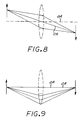
- FIG. 8 shown therein is a simple off-axis lens system illustrating the use of "off-axis" in conjunction with the invention.
- the central axis CA that joins the center of the object and the center of the image is not coincident with the optical axis OA of the lens, and thus the central axis is "off-axis" as are the object and image.
- the off-axis configuration is initially set up relative to the optical axis of a spherical element which is then distorted as described above to achieve the appropriate aspheric surface.
- FIG. 9 shown therein is a simple lens system illustrating known on-axis systems that utilize a portion of an optical element that is positioned off-axis relative to the optical axis of the optical element, where such optical axis is defined by the base radius of the optical element. While an off-axis portion of an optical element is used, the central axis that joins the center of the object and the center of the image is coincident with the optical axis OA and thus "on-axis," as are the object and image (i.e., the object and image lie on the optical axis).
- the second image source comprising an alphanumeric display can be larger than those utilized with a single mirror system, which permits more detail in the graphics.
- image sources can be utilized, including for example segmented graphical displays, and that both image sources can be of the same type; i.e., both can be electromechanical, alpha-numeric, or segmented graphical displays, for example.
Description
- The disclosed invention is directed generally to virtual image displays, and is more particularly directed to a virtual image display for vehicle instrumentation which provides a plurality of different displays in the same location.
- WO 89/02611 discloses a virtual image display for a vehicle that has the features of the pre-characterising part of Claim 1.
- Vehicle instrumentation commonly includes primary instrumentation which is located in front of the operator, for example, in a traditional instrument cluster positioned in front of the steering wheel. Secondary instruments, including, for example, radio control status indicators, environment control status indicators, trip computer controls and indicators, maintenance annunciators, and message indicators, are commonly located in a center-mounted panel. With advances in display technology, the displays of the secondary instruments are being implemented with vacuum fluorescent displays (VFDs) or cathode ray tubes (CRTs).
- A consideration with the separation of primary and secondary instruments, however, includes the required head and eye motion for reading the secondary instruments, producing at least a nuisance if not a potential hazard.
- It would therefore be an advantage to provide a vehicle instrumentation display that provides for display of primary and secondary instrumentation at the same position ahead of the vehicle operator.
- Another advantage would be to provide a vehicle instrumentation display that permits the selective display of different types of information at the same position ahead of the driver.
- The foregoing and other advantages are provided by the invention, as specified in Claim 1 hereinafter, in a virtual image display for vehicles that includes a first image source for providing first imaging illumination, second image source for providing second imaging illumination, a combiner responsive to the first and second imaging illumination for providing combiner imaging illumination, a negative power aspheric off-axis mirror responsive to the combiner imaging illumination for providing diverging reflected imaging illumination, and a positive power aspheric off-axis mirror responsive to the diverging imaging illumination for providing converging reflected imaging illumination that produces a virtual image of the image sources observable by the vehicle operator. By way of example, the first and second image sources can be selectively illuminated so as to display only one image source at any given time, or they can he selectively illuminated so that the first image source provides certain components of the virtual image while the second image source provides other components of the virtual image.
- The advantages and features of the disclosed invention will readily be appreciated by persons skilled in the art from the following detailed description when read in conjunction with the drawing wherein:
- FIG. 1 is an elevational sectional view schematically illustrating the disclosed two-page virtual image display.
- FIG. 2 is a schematic illustration of a display produced by one of the image sources of the display of FIG. 1.
- FIG. 3 is a schematic illustration of a display produced by the other image source of the display of FIG. 1.
- FIG. 4 is an elevational view of a single lens display system that is helpful in understanding the virtual image display of FIG. 1.
- FIG. 5 is an elevational view of a dual lens display system that is an unfolded version of the virtual image display of FIG. 1 and is helpful in understanding the virtual image display of FIG. 1.
- FIGS. 6A and 6B are side and front views of an illustrative example of the negative power mirror of the virtual image display of FIG. 1.
- FIGS. 7A and 7B are side and front views of an illustrative example of the positive power mirror of the virtual image display of FIG. 1.
- FIG. 8 is a schematic view illustrating an off-axis lens system that is helpful in understanding the off-axis configuration of the virtual image display of the invention.
- FIG. 9 is a schematic view of an on-axis lens system that utilizes an off-axis portion of a lens that is helpful in understanding known off-axis systems that utilize off-axis portions of optical elements.
- In the following detailed description and in the several figures of the drawing, like elements are identified with like reference numerals.
- Referring now to FIG. 1, shown therein is a virtual image display system for a vehicle in accordance with the invention. The virtual image display can be located, for example, above the vehicle steering column and ahead of the steering wheel, for example, generally in the region traditionally occupied by an instrument panel.
- The display system includes a first image source 11 and a planar combiner 13 for reflecting at least a portion of the imaging illumination from the first image source 11. A
second image source 12 provides second imaging illumination to the planar combiner 13 which transmits at least a portion of the second imaging illumination. The reflected first imaging illumination and the transmitted second imaging illumination are directed to an off-axis convex negative power mirror 15 which provides for diverging reflected illumination. The mirror 15 is characterized as having negative power since it would produce image reduction if viewed directly, and is further characterized as providing for diverging reflection since parallel rays incident thereon would diverge upon reflection. - The illumination from the negative power mirror 15 is incident upon an off-axis concave
positive power mirror 17 which provides for converging reflected illumination. Themirror 17 is characterized as having positive power since it provides for image magnification, and is further characterized as providing for converging reflection since parallel rays incident thereon would converge upon reflection. - The illumination reflected by the
positive power mirror 17 passes through a curved protective window 19 to the observer. The curved protective window 19 is more particularly, as viewed from outside the display system, a concave portion of an elliptically shaped cylinder that is configured so that the reflections therefrom that can be seen by the observer will be limited to reflections of a darkened light trap located above the protective window. - By way of illustrative example, the first image source 11 comprises (a) a group of electromechanical gauges for indicating speed, engine RPMs, oil temperature, oil pressure, and fuel level, for example; and (b) annunciator lights for turn-signals, high beam, and emergency engine indications, for example. FIG. 2 sets forth a schematic illustration of an example of the display that can be produced by the first image source.
- By way of further illustrative example, the second image source comprises a large alpha-numeric display, such as a VFD or a liquid crystal display (LCD), for example, for providing alphanumeric information such as messages, maintenance instructions, and environmental status and settings. FIG. 3 sets forth a schematic illustration of an example of the display that can be produced by the second image source.
- The combiner 13 comprises a half-silvered mirror or a dielectric dichroic mirror, for example. By way of particular example, the dichroic mirror is configured to reflect illumination in the yellow/orange/red region of the spectrum and to transmit illumination in the blue/green region. The electromechanical gauges of the first image source would be illuminated with appropriately filtered incandescent bulbs, and the annunciator lights would be configured to produce the appropriate light for reflection by the dichroic mirror. The VFD is self luminous and its output would be in the appropriate spectrum range for transmission by the dichroic mirror.
- In operation, the first and second image sources can be displayed independently to provide a two-page display wherein the source to be displayed would illuminated while the other source would not be illuminated. Also, portions of each display can be selectively illuminated so as to produce a virtual image that comprises the illuminated portions from each image source. For example, the speedometer in the first image source can be the only first image source component illuminated, and selected portions of the second image source are illuminated to produce virtual image components around the speedometer virtual image.
- The negative and
positive power mirrors 15 and 17 have aspheric, non-rotationally symmetrical reflecting surfaces, and can comprise, for example, injection molded or cast molded plastic substrates having requisite aspheric surfaces which are coated with a metallic reflective coating. - The
aspheric elements 15, 17 have respective optical axes OA1, OA2 which are the optical axes defined by the base radii of the respective reflecting surfaces prior to being aspherically deformed. The optical axes pass through the optical axis points P1, P2 which are utilized as the origins of the respective coordinate systems utilized to define the aspheric deformation of the respective surfaces. In other words, the optical axis points P1, P2 and the axes passing therethrough remain fixed while the surrounding areas are aspherically deformed. - For the reflecting surface of the negative mirror 15, the optical axis OA1 bisects the incidence and reflection portions of a central axis CA which is defined by the ray that joins the image source center with the image center and passes through the optical axis points P1, P2. For the reflecting surface of the
positive mirror 17, the optical axis OA2 also bisects the incidence and reflection portions of the central axis CA. - Relative to the optical axes OA1, OA2, the aspheric elements are off-axis since the central axis CA is not colinear with the optical axes, and the image source and image do not lie on the optical axes of the aspheric elements including any reflective folds thereof.
- The central axis CA further defines an optical path travelled by the imaging illumination from the image source to the eyes of the vehicle operator, and as discussed further herein such optical path has a distance that is greater than the effective viewing distance of the virtual image (i.e., the distance at which the operator's eyes focus in order to view the virtual image).
- It is noted that although prior systems have used mirrors comprising off-axis portions of spherical or aspherical sections of a conic (e.g., paraboloid), such systems place the image source on the optical axis of the conic sections used to define the mirrors. This is done to maintain some rotational symmetry for ease of fabrication. However, this limits the performance of such optical systems by constraining the degree of asphericity that one can apply to the mirror surfaces. The optical system described in this invention does away with this restriction by placing the image source off-axis, thereby decoupling the optical axis of the aspheric surface from the image source. The aspheric mirrors of the invention are not rotationally symmetric, taking any shape that improves the overall visual performance. This added degree of design freedom allows this invention to exceed the performance of previous designs.
- The negative mirror 15 is the smaller mirror and is positioned relative to the larger
positive mirror 17 pursuant to relatively simple optical formulae (e.g., as in a Cassegrain telescope) to achieve a reasonable magnification range for a magnified virtual image without necessitating a change in the sizes of theimage source 11, 12 or the virtual image range (i.e., the effective distance at which the viewer's eyes focus to see the virtual image). In accordance with the invention, the virtual image range is in the range of about 4 to 12 feet, which is greater than the typical distance between the driver's eyes and direct view instrumentation in an instrument panel. - The use of a negative mirror and a positive mirror provides for appropriate magnification, virtual image range, field of view, and optical performance (i.e., reduction of distortion and disparity), while maintaining an optical system length (i.e., the distance between the image source and the mirror optically closest to the nominal eye position) that is more compact than a single, positive mirror system having comparable parameters. In other words, for a given magnification, virtual image range, field of view, and optical performance, the disclosed dual mirror system would have a shorter system length than a comparable single positive mirror system and therefore a smaller optical package.
- The compactness of the dual mirror system results from the reverse telephoto arrangement of the negative and positive mirrors, which provides for an increased working focal length without a significant increase in the system length. The working focal length is the distance from the image source to the "first principle plane" which, as is well known, is located at the position at which a single lens or mirror would be located to produce a single lens or mirror optical system having substantially the same parameters. The first principle plane for the dual mirror system is located between the nominal eye position and the mirror optically closest thereto, while the first principle plane for a single positive mirror system is located at the mirror. In other words, the first principle plane for the dual mirror system is not constrained to be at the physical location of one of the optical elements.
- The factors that allow the dual mirror system to achieve a more compact system length can be better understood by a comparison of the single and dual lens systems respectively depicted in FIGS. 4 and 5, which essentially are unfolded versions of a single lens system and a dual mirror system, and are easier to understand. The pertinent optical parameters are as follows:
Range (R): The distance from the nominal eye position to the virtual image.
Eye Relief (L): The distance from the nominal eye position to the first lens surface.
Eye Box (Y): The diameter of the space about the nominal eye position where the virtual image can be viewed without any vignetting.
Field of View (FOV): The angular substance of the virtual image as viewed from the nominal eye position.
System Length (Z): The distance between the lens closest to the eye and the image source.
Back Focus (B): The distance from the image source to the lens nearest the image source.
Working Focal Length (F): The distance from the image source to the first principle plane of the optical system.
Working Diameter (D): The diameter of the first principle plane.
Working F-Number (F/#): The ratio of the working focal length and the working diameter (i.e., F/D).
Image Source Size (H): The height (in the vertical plane) of the image source.
Virtual Image Size (H'): The height (in the vertical plane) of the virtual image. - The optical performance of the respective single and dual lens systems (i.e., the reduction of distortion and disparity) is directly related to the working F/#. In particular, performance deteriorates as the working F/# is decreased. Therefore, for a given performance specification, the working F/# is generally fixed. Also, it may be desirable to make the system length Z as short as practicable to minimize the optical package.
- For a single lens system as shown in FIG. 4, the working focal length F, the back focus B, and the system length Z are equal. The working diameter D is simply the diameter of the lens. For a given range R, eye relief L, eye box size Y, and and field of view FOV, the working diameter D can be expressed as follows:


- A single lens system provides adequate performance if the image sources can be arbitrarily sized to match the image source size requirements discussed above. Such sizing can be achieved if the image sources comprise liquid crystal displays (LCDs) or VFDs wherein the size of the graphics can be readily changed to be sufficiently small. However, electromechanical gauges cannot be miniaturized smaller than a certain size, for example, about one inch in diameter. Given the size constraint for an analog image source, the foregoing equations will need to be applied in reverse starting with a given image source size.
- If the analog gauge is larger than the proposed image source size dictated by the equations, then both the working focal length and the FOV will have to increase for a constant working F/#. If the FOV must remain constant, then the working diameter will also be constant, and the only way to use a larger image source size will be to increase the F/#. This will also increase the working focal length (even greater than in the case where the FOV can be increased). Given that an analog gauge image source cannot be made as small as an LCD or VFD source, the net result is that the system length must be increased for a single lens system if an analog gauge is used as the image source. A longer system means a longer box and an overall increase in the optical package size.
- Consider now the dual lens system of FIG. 5 which is the unfolded version of the disclosed dual mirror system, and functions as a reverse telephoto arrangement that provides for an increased working focal length without an increase in the system length. For simplicity, the range is set to infinity as above relative to the single lens system. The focal length of the two lenses are f1 and f2, with f1 being a positive focal length and f2 a negative focal length. The distance between the two lenses is x. Therefore, the working focal length of this system is:


- If the image source size is changed while keeping the working F/# and the field of view FOV constant, the working focal length is set by Equation 8; the working diameter D is set by the working F/#; and L1 is set by Equation 7. Equation 6 can then be solved for the quantity (x + B) which is the system length.
- As an example of the difference between the single and dual-lens systems, the optical parameters for the single and dual-lens systems will be calculated for the following system specification:

- Using Equation 2 for a single lens system, the working diameter must be 3.757 inches which requires a focal length of 7.514 inches (from

- Consider now the use of an analog gauge package that is one inch in size for the image source. From Equation 4 and keeping the FOV at 3°, the focal length must increase to 19.094 inches. This is a 150% increase in the system length. The working diameter will remain at 3.757 inches leaving us with an F/# of 5.082.
- If the system length of 19.094 inches cannot be tolerated, the FOV can be changed to reduce the focal length. By substituting (D)(F/#) for the focal length F in Equation 2, and by substituting the expression for D from Equation 2, the image source can be related to the working F/# and the FOV:

- The dual lens approach will now be analyzed for an image source size of one inch. From Equation 8, the working focal length is 19.094 inches for a 3° FOV. Setting the distance between the two lenses, x, to be 3 inches and setting the system length to be 7.514 inches (the shortest possible single lens design for the specified eye relief L, eyebox Y, and field of view FOV), the back focus will be 4.514 inches. From Equation 6, L1 is then equal to 12.42 inches. The focal lengths of each lens can vary relative to one another, but one solution from Equation 5 is that f1 is 7.568 inches and f2 is -7.568 inches. Since the size of f1 is the same as the working diameter of the single lens system of 3.757, the F/# of f1 is 2.014.
- From the foregoing comparison, it should be appreciated that for a specified image source size along with the optical specification of range, FOV, etc., the dual lens system provided for a system length that is comparable to a single lens system having a smaller image source size. It is also pointed out that since the working F/#'s of the individual lenses in the dual lens system are not too fast, the optical performance will be better than the single lens approach since there are two lenses to optimize.
- As to the implementation of the disclosed dual mirror virtual display system, the foregoing analysis of the dual lens system could be utilized to arrive at a first-order design, which would be followed by utilizing an optical design computer program with the spherical mirror versions of the first-order design. With the computer program, the nominal spherical surfaces are deformed to meet the desired criteria of minimizing distortions when viewed in the eyebox. Since the eyebox and virtual image are off-axis with respect to the individual axes of the two mirrors, the equation of the aspheric surfaces can be adjusted independently from the axis joining the eye and the virtual image. This provides for greater latitude in the design process and will better correct the optical aberrations and distortions. Such distortions can cause vertical disparity and magnification variations that are objectionable in the final design.
- Referring now to FIGS. 6A, 6B, 7A, 7B, the following sets forth illustrative examples of the aspheric reflecting surfaces of the negative and positive mirrors for a dual mirror virtual image display in accordance as in this invention, wherein the surfaces have aspherically deformed to reduce distortions. The dimensions of the mirrors shown in these figures is in inches.
- The aspheric surface of the illustrative example of the negative mirror satisfies the following surface equation relative to the coordinate system shown in FIGS. 6A and 6B:

where Ci and F(X,Y)i are as follows:i Ci F(X,Y)i 1 -0.152819 x 10⁻¹ X²-Y² 2 -0.228226 x 10⁻² Y(X²+Y² 3 -0.384185 x 10⁻² Y(3X²-Y²) 4 -0.279668 x 10⁻³ X⁴-Y⁴ 5 -0.652462 x 10⁻⁶ Y(X²+Y²)²
and S(X,Y) is:
- The following table sets forth data for sample points (in inches) along the aspheric surface of the negative mirror:
-
X Y Z +1 0 -0.057928 0 +1 -0.025244 0 -1 -0.028365 +1 +1 -0.097131 +1 -1 -0.072639 - The aspheric surface of the positive mirror utilized with the foregoing described negative mirror satisfies the following surface equation relative to the coordinate system shown in FIGS. 7A and 7B:

where Ci and F(X,Y) are as follows:i Ci F(X,Y)i 1 -0.617592 x 10⁻² X²-Y² 2 -0.593066 x 10⁻³ Y(X²+Y² 3 -0.560451 x 10⁻³ Y(3X²-Y²) 4 -0.206953 x 10⁻⁴ X⁴-Y⁴ 5 -0.181196 x 10⁻⁴ Y(X²+Y²)²
and S(X,Y) is:
- The following table sets forth data for sample points (in inches) along the aspheric surface of the positive mirror:
-
X Y Z +1 0 -0.041533 0 +1 -0.029191 0 -1 -0.029089 +1 +1 -0.073142 +1 -1 -0.068383 - The foregoing mirror surfaces can be utilized in a display system having the following parameters:
Range R: 80 inches
Eye Relief L: 24 inches
Back Focus B: 5.7 inches
System Length Z: 9 inches
Image Source Size: 1.25 by 5 inches
Virtual Image Size: 4° x 16° at 80 inch range
It should be appreciated that the optical axes OA1, OA2 of the aspheric elements described above are along the respective Z axes of the respective coordinate systems utilized to define the aspheric deformation of the respective surfaces, that the central axis CA of the display system that includes the aspheric elements passes through the origins of such coordinate systems, and that such origins correspond to the optical axis points P1, P2. - Referring now to FIG. 8, shown therein is a simple off-axis lens system illustrating the use of "off-axis" in conjunction with the invention. The central axis CA that joins the center of the object and the center of the image is not coincident with the optical axis OA of the lens, and thus the central axis is "off-axis" as are the object and image. In the invention, the off-axis configuration is initially set up relative to the optical axis of a spherical element which is then distorted as described above to achieve the appropriate aspheric surface.
- Referring now to FIG. 9, shown therein is a simple lens system illustrating known on-axis systems that utilize a portion of an optical element that is positioned off-axis relative to the optical axis of the optical element, where such optical axis is defined by the base radius of the optical element. While an off-axis portion of an optical element is used, the central axis that joins the center of the object and the center of the image is coincident with the optical axis OA and thus "on-axis," as are the object and image (i.e., the object and image lie on the optical axis).
- From the foregoing, it should be appreciated that as a result of the configuration of the optical elements for use with electromechanical analog gauges, the second image source comprising an alphanumeric display can be larger than those utilized with a single mirror system, which permits more detail in the graphics. It should also be appreciated that different types of image sources can be utilized, including for example segmented graphical displays, and that both image sources can be of the same type; i.e., both can be electromechanical, alpha-numeric, or segmented graphical displays, for example.
- The foregoing has been a disclosure of a compact virtual image display system which can advantageously display different vehicle instrumentation information at different times at the same location, which reduces the amount of dashboard space required for instrumentation and further enhances the ease of viewing the instrumentation. Further, the use of magnification permits the use of smaller alphanumeric image sources which are less expensive than the larger direct view versions.
- Although the foregoing has been a description and illustration of specific embodiments of the invention, various modifications and changes thereto can be made by persons skilled in the art without departing from the scope and spirit of the invention as defined by the following claims.
Claims (4)
- A virtual image (11, 12) display for a vehicle comprising:
image source means for providing imaging illumination; and
aspheric off-axis optical means (15, 17) for providing imaging illumination that produces a virtual image in response to said imaging source means imaging illumination, said aspheric optical means being off-axis whereby the image source and the virtual image do not lie on the optical axis (OA1, OA2) of the aspheric optical means (15, 17) and being aspherically deformed to reduce distortions including distortions produced by the off-axis configuration;
said display being characterised in that:(a) said image source means comprises first image source means (11) for providing first imaging illumination, and second image source means (12) for providing second image illumination; and(b) there is provided a combiner (13) responsive to said first and second imaging illumination for providing combiner imaging illumination; and(c) said aspheric off-axis optical means comprises: negative power aspheric off-axis optical means (15) responsive to said combiner imaging illumination for providing diverging imaging illumination; and
positive power aspheric off-axis optical means (17) responsive to said diverging imaging illumination for providing converging imaging illumination that produces a virtual image of said first image source and said second image source observable by an operator of the vehicle; and
wherein one of said first (11) and second (12) image sources includes a plurality of electromechanical vehicle instrument gauges; and
wherein the other of said first (11) and second (12) image sources comprises an alpha-numeric display. - The virtual image display of claim 1 wherein said aspheric off-axis optical means are mirrors.
- The virtual image display of claim 1 wherein said combiner (13) comprises a partially reflecting mirror for reflecting said first imaging illumination and for transmitting said second image illumination.
- The virtual image display of claim 1 wherein said combiner (13) comprises a dichroic mirror for reflecting said first imaging illumination and for transmitting said second imaging illumination.
Applications Claiming Priority (2)
| Application Number | Priority Date | Filing Date | Title |
|---|---|---|---|
| US07/602,018 US5121099A (en) | 1990-08-31 | 1990-10-23 | Two-page automotive virtual image display |
| US602018 | 1990-10-23 |
Publications (2)
| Publication Number | Publication Date |
|---|---|
| EP0482805A1 EP0482805A1 (en) | 1992-04-29 |
| EP0482805B1 true EP0482805B1 (en) | 1995-11-22 |
Family
ID=24409643
Family Applications (1)
| Application Number | Title | Priority Date | Filing Date |
|---|---|---|---|
| EP91309428A Expired - Lifetime EP0482805B1 (en) | 1990-10-23 | 1991-10-14 | Two-page automotive virtual image display |
Country Status (6)
| Country | Link |
|---|---|
| US (1) | US5121099A (en) |
| EP (1) | EP0482805B1 (en) |
| JP (1) | JPH0764233B2 (en) |
| KR (1) | KR940008685B1 (en) |
| DE (1) | DE69114814T2 (en) |
| MX (1) | MX9101712A (en) |
Cited By (3)
| Publication number | Priority date | Publication date | Assignee | Title |
|---|---|---|---|---|
| WO2005018976A1 (en) | 2003-07-23 | 2005-03-03 | Volkswagen Aktiengesellschaft | Display device for a motor vehicle |
| DE102008022011A1 (en) * | 2008-05-02 | 2009-11-05 | Becker, Stefanie | Device for virtual representation of a light source and use of this |
| CN101678770B (en) * | 2007-05-14 | 2012-11-21 | 雷诺股份公司 | Glass for a vehicle dashboard |
Families Citing this family (42)
| Publication number | Priority date | Publication date | Assignee | Title |
|---|---|---|---|---|
| US5371510A (en) * | 1990-11-28 | 1994-12-06 | Nippondenso Co., Ltd. | Automotive information display apparatus |
| JP2535571Y2 (en) * | 1990-12-26 | 1997-05-14 | 矢崎総業株式会社 | Display device for vehicles |
| US5406303A (en) * | 1991-05-09 | 1995-04-11 | Nu-Tech And Engineering, Inc. | Instrument display method and system for passenger vehicle |
| US5376917A (en) * | 1991-08-19 | 1994-12-27 | Mitsubishi Jidosha Kogyo Kabushiki Kaisha | Vehicle display apparatus with drive information |
| JP2554567B2 (en) * | 1991-10-02 | 1996-11-13 | スタンレー電気株式会社 | How to display road information |
| US5805119A (en) * | 1992-10-13 | 1998-09-08 | General Motors Corporation | Vehicle projected display using deformable mirror device |
| IL107441A (en) * | 1992-11-05 | 1997-09-30 | Hughes Aircraft Co | Virtual image instrument panel display |
| EP0614104A3 (en) * | 1993-03-05 | 1995-12-20 | Hughes Aircraft Co | Virtual image display management system with head-up display. |
| DE4319904C2 (en) * | 1993-06-16 | 2002-11-28 | Siemens Ag | Warning device for displaying information in a vehicle |
| US7262919B1 (en) * | 1994-06-13 | 2007-08-28 | Canon Kabushiki Kaisha | Head-up display device with curved optical surface having total reflection |
| US5644323A (en) * | 1994-12-21 | 1997-07-01 | Siliscape, Inc. | Miniature synthesized virtual image electronic display |
| US5684497A (en) * | 1994-12-21 | 1997-11-04 | Siliscape, Inc. | Twice folded compound magnified virtual image electronic display |
| JP3658034B2 (en) * | 1995-02-28 | 2005-06-08 | キヤノン株式会社 | Image observation optical system and imaging optical system |
| US5771124A (en) * | 1996-07-02 | 1998-06-23 | Siliscape | Compact display system with two stage magnification and immersed beam splitter |
| US6433935B2 (en) * | 1996-07-02 | 2002-08-13 | Three-Five Systems, Inc. | Display illumination system |
| CA2306915A1 (en) * | 1997-11-03 | 1999-05-14 | Douglas Hall | Virtual instrument panel |
| US5982550A (en) * | 1998-06-17 | 1999-11-09 | Chrylser Corporation | Viewing angle lens |
| JP2000098293A (en) | 1998-06-19 | 2000-04-07 | Canon Inc | Image observing device |
| US6128145A (en) * | 1998-11-25 | 2000-10-03 | Fit Corporation | Image pick-up device, image display device and information recording medium comprising a fisheye lens |
| US20050102621A1 (en) * | 2002-04-05 | 2005-05-12 | Siemens Vdo Automotive Corporation | Clean dash instrument cluster |
| US6842677B2 (en) * | 2003-02-28 | 2005-01-11 | Prakash S. Pathare | Vehicle user interface system and method |
| DE10347300A1 (en) * | 2003-10-08 | 2005-05-04 | Daimler Chrysler Ag | Display system for a vehicle |
| US6956544B2 (en) * | 2003-12-22 | 2005-10-18 | Motorola, Inc. | Dual mode display |
| JP2005239042A (en) * | 2004-02-27 | 2005-09-08 | Nippon Seiki Co Ltd | Information display device for vehicle and information display method for vehicle |
| DE102005012848A1 (en) | 2004-04-05 | 2005-11-03 | Volkswagen Ag | Built-in instrument cluster |
| FR2873331B1 (en) * | 2004-07-23 | 2006-09-29 | Peugeot Citroen Automobiles Sa | DATA DISPLAY DEVICE |
| DE102004054769B4 (en) * | 2004-11-12 | 2016-12-22 | Volkswagen Ag | Built-in combination instrument for a motor vehicle |
| DE102005011093B4 (en) * | 2005-03-08 | 2017-05-24 | Volkswagen Ag | Display device for a motor vehicle |
| DE102005029800A1 (en) * | 2005-06-27 | 2007-01-04 | Volkswagen Ag | Instrument cluster for a motor vehicle |
| KR100716829B1 (en) * | 2005-08-10 | 2007-05-09 | 삼성전기주식회사 | Mobile camera optical system and method for producing image thereof |
| DE102006032118B4 (en) | 2006-07-12 | 2022-03-03 | Volkswagen Ag | Instrument cluster for a motor vehicle and motor vehicle |
| KR20090052169A (en) * | 2007-11-20 | 2009-05-25 | 삼성전자주식회사 | Head-mounted display |
| CN103507639B (en) * | 2012-06-27 | 2016-06-01 | 比亚迪股份有限公司 | A kind of car-mounted display equipment and there is the vehicle of this equipment |
| US9316828B2 (en) | 2012-08-22 | 2016-04-19 | Honda Motor Co., Ltd. | Three-dimensional vehicle backup camera display system and method |
| US20140282182A1 (en) * | 2013-03-15 | 2014-09-18 | Honda Moror Co., Ltd. | Multi-layered vehicle display system and method |
| JP6094399B2 (en) * | 2013-06-24 | 2017-03-15 | 株式会社デンソー | Head-up display and program |
| US9291819B2 (en) | 2013-09-05 | 2016-03-22 | Texas Instruments Incorporated | Multi-focus heads-up display using single picture generator unit |
| JP5957709B2 (en) | 2013-12-27 | 2016-07-27 | パナソニックIpマネジメント株式会社 | Display device and display unit |
| JP2015194707A (en) * | 2014-03-27 | 2015-11-05 | パナソニックIpマネジメント株式会社 | display device |
| JPWO2016079927A1 (en) * | 2014-11-19 | 2017-09-07 | パナソニックIpマネジメント株式会社 | Head-up display and vehicle |
| JP6365269B2 (en) * | 2014-11-28 | 2018-08-01 | アイシン・エィ・ダブリュ株式会社 | Virtual image display device |
| FR3118203B1 (en) * | 2020-12-21 | 2022-11-04 | Psa Automobiles Sa | Vehicle display device with configurable virtual image |
Family Cites Families (8)
| Publication number | Priority date | Publication date | Assignee | Title |
|---|---|---|---|---|
| US3230819A (en) * | 1962-07-25 | 1966-01-25 | Bendix Corp | Optical display means for an all weather landing system of an aircraft |
| US3697154A (en) * | 1971-05-12 | 1972-10-10 | Us Navy | Optical viewing system |
| GB2076557B (en) * | 1980-05-27 | 1984-09-19 | Kaufman Arthur | Virtual image display apparatus |
| US4694447A (en) * | 1984-07-12 | 1987-09-15 | International Business Machines Corp. | Optical signal recorders employing two lasers and methods therefor |
| FR2578330B1 (en) * | 1985-03-01 | 1989-03-31 | Thomson Csf | AIRPORT SYSTEM FOR VIEWING COLLIMATED IMAGES |
| GB8719854D0 (en) * | 1987-08-21 | 1987-09-30 | Secr Defence | Optical system |
| US5278532A (en) * | 1987-09-14 | 1994-01-11 | Hughes Aircraft Company | Automotive instrument virtual image display |
| US4973139A (en) * | 1989-04-07 | 1990-11-27 | Hughes Aircraft Company | Automotive head-up display |
-
1990
- 1990-10-23 US US07/602,018 patent/US5121099A/en not_active Expired - Lifetime
-
1991
- 1991-10-14 DE DE69114814T patent/DE69114814T2/en not_active Expired - Fee Related
- 1991-10-14 EP EP91309428A patent/EP0482805B1/en not_active Expired - Lifetime
- 1991-10-22 KR KR1019910018578A patent/KR940008685B1/en not_active IP Right Cessation
- 1991-10-23 JP JP3302695A patent/JPH0764233B2/en not_active Expired - Lifetime
- 1991-10-23 MX MX9101712A patent/MX9101712A/en unknown
Cited By (3)
| Publication number | Priority date | Publication date | Assignee | Title |
|---|---|---|---|---|
| WO2005018976A1 (en) | 2003-07-23 | 2005-03-03 | Volkswagen Aktiengesellschaft | Display device for a motor vehicle |
| CN101678770B (en) * | 2007-05-14 | 2012-11-21 | 雷诺股份公司 | Glass for a vehicle dashboard |
| DE102008022011A1 (en) * | 2008-05-02 | 2009-11-05 | Becker, Stefanie | Device for virtual representation of a light source and use of this |
Also Published As
| Publication number | Publication date |
|---|---|
| KR920008518A (en) | 1992-05-28 |
| EP0482805A1 (en) | 1992-04-29 |
| JPH04278840A (en) | 1992-10-05 |
| JPH0764233B2 (en) | 1995-07-12 |
| KR940008685B1 (en) | 1994-09-24 |
| DE69114814T2 (en) | 1996-08-08 |
| US5121099A (en) | 1992-06-09 |
| DE69114814D1 (en) | 1996-01-04 |
| MX9101712A (en) | 1992-06-05 |
Similar Documents
| Publication | Publication Date | Title |
|---|---|---|
| EP0482805B1 (en) | Two-page automotive virtual image display | |
| US6147807A (en) | High brightness see-through head-mounted display | |
| KR920001123B1 (en) | Automotive instrument virtual image display | |
| US4383740A (en) | Infinity image visual display system | |
| US5357372A (en) | Ultra-compact, wide field of view virtual image display optical system | |
| US11640050B2 (en) | Microdisplay-based head-up display system | |
| JP2705880B2 (en) | Broad spectrum band virtual image display optical system | |
| US5576887A (en) | Head gear display system using off-axis image sources | |
| EP0391231A2 (en) | Automotive head-up display | |
| KR20020021091A (en) | Head-Up Display | |
| US5731903A (en) | Virtual image instrument panel display | |
| US7636199B2 (en) | Optical device for superposing electronic images in front of an objective | |
| US5313326A (en) | Car head-up display including a Fresnel mirror and a curved mirror | |
| EP0431488B1 (en) | Dual-mirror virtual image display for vehicle instrument cluster | |
| WO2017041212A1 (en) | Collimation display apparatus, and vehicle-mounted or airborne head-up display apparatus | |
| TW202001338A (en) | Display device and automobile head-up display system using the same | |
| KR950010029B1 (en) | Dual-mirror virtual image display for vehicle | |
| CA2052437C (en) | Two-page automotive virtual image display | |
| Patterson et al. | Automotive head-up display | |
| JPH08169260A (en) | Display system and head-up display device | |
| CN219957989U (en) | Head-up display system and vehicle | |
| CN117270219A (en) | Display system | |
| Shin et al. | Portable virtual display system design with a wide eye motion box for a motor vehicle | |
| Gan et al. | Automotive collimator displays | |
| CN116520576A (en) | Vehicle-mounted head-up display optical system with ultra-large visual field, mechanical packaging structure and electronic circuit |
Legal Events
| Date | Code | Title | Description |
|---|---|---|---|
| PUAI | Public reference made under article 153(3) epc to a published international application that has entered the european phase |
Free format text: ORIGINAL CODE: 0009012 |
|
| AK | Designated contracting states |
Kind code of ref document: A1 Designated state(s): DE FR GB IT SE |
|
| 17P | Request for examination filed |
Effective date: 19921006 |
|
| 17Q | First examination report despatched |
Effective date: 19940330 |
|
| GRAA | (expected) grant |
Free format text: ORIGINAL CODE: 0009210 |
|
| AK | Designated contracting states |
Kind code of ref document: B1 Designated state(s): DE FR GB IT SE |
|
| REF | Corresponds to: |
Ref document number: 69114814 Country of ref document: DE Date of ref document: 19960104 |
|
| ITF | It: translation for a ep patent filed |
Owner name: SOCIETA' ITALIANA BREVETTI S.P.A. |
|
| ET | Fr: translation filed | ||
| PLBE | No opposition filed within time limit |
Free format text: ORIGINAL CODE: 0009261 |
|
| STAA | Information on the status of an ep patent application or granted ep patent |
Free format text: STATUS: NO OPPOSITION FILED WITHIN TIME LIMIT |
|
| 26N | No opposition filed | ||
| PGFP | Annual fee paid to national office [announced via postgrant information from national office to epo] |
Ref country code: FR Payment date: 19970910 Year of fee payment: 7 |
|
| PGFP | Annual fee paid to national office [announced via postgrant information from national office to epo] |
Ref country code: SE Payment date: 19970918 Year of fee payment: 7 Ref country code: GB Payment date: 19970918 Year of fee payment: 7 |
|
| PGFP | Annual fee paid to national office [announced via postgrant information from national office to epo] |
Ref country code: DE Payment date: 19970922 Year of fee payment: 7 |
|
| PG25 | Lapsed in a contracting state [announced via postgrant information from national office to epo] |
Ref country code: GB Free format text: LAPSE BECAUSE OF NON-PAYMENT OF DUE FEES Effective date: 19981014 |
|
| PG25 | Lapsed in a contracting state [announced via postgrant information from national office to epo] |
Ref country code: SE Free format text: LAPSE BECAUSE OF NON-PAYMENT OF DUE FEES Effective date: 19981015 |
|
| GBPC | Gb: european patent ceased through non-payment of renewal fee |
Effective date: 19981014 |
|
| EUG | Se: european patent has lapsed |
Ref document number: 91309428.0 |
|
| PG25 | Lapsed in a contracting state [announced via postgrant information from national office to epo] |
Ref country code: FR Free format text: LAPSE BECAUSE OF NON-PAYMENT OF DUE FEES Effective date: 19990630 |
|
| REG | Reference to a national code |
Ref country code: FR Ref legal event code: ST |
|
| PG25 | Lapsed in a contracting state [announced via postgrant information from national office to epo] |
Ref country code: DE Free format text: LAPSE BECAUSE OF NON-PAYMENT OF DUE FEES Effective date: 19990803 |
|
| PGFP | Annual fee paid to national office [announced via postgrant information from national office to epo] |
Ref country code: IT Payment date: 20061031 Year of fee payment: 16 |
|
| PG25 | Lapsed in a contracting state [announced via postgrant information from national office to epo] |
Ref country code: IT Free format text: LAPSE BECAUSE OF NON-PAYMENT OF DUE FEES Effective date: 20071014 |