EP0483664B1 - Goal oriented electronic form system - Google Patents
Goal oriented electronic form system Download PDFInfo
- Publication number
- EP0483664B1 EP0483664B1 EP91118111A EP91118111A EP0483664B1 EP 0483664 B1 EP0483664 B1 EP 0483664B1 EP 91118111 A EP91118111 A EP 91118111A EP 91118111 A EP91118111 A EP 91118111A EP 0483664 B1 EP0483664 B1 EP 0483664B1
- Authority
- EP
- European Patent Office
- Prior art keywords
- field
- data
- forms
- fields
- tree
- Prior art date
- Legal status (The legal status is an assumption and is not a legal conclusion. Google has not performed a legal analysis and makes no representation as to the accuracy of the status listed.)
- Expired - Lifetime
Links
Images


Classifications
-
- G—PHYSICS
- G06—COMPUTING; CALCULATING OR COUNTING
- G06F—ELECTRIC DIGITAL DATA PROCESSING
- G06F8/00—Arrangements for software engineering
- G06F8/30—Creation or generation of source code
- G06F8/34—Graphical or visual programming
-
- G—PHYSICS
- G06—COMPUTING; CALCULATING OR COUNTING
- G06F—ELECTRIC DIGITAL DATA PROCESSING
- G06F40/00—Handling natural language data
- G06F40/10—Text processing
- G06F40/166—Editing, e.g. inserting or deleting
- G06F40/174—Form filling; Merging
Definitions
- This invention relates to a programmable controlled, goal oriented electronic system for form creation and form completion according to the preamble of claim 1.
- Forms to gather data are employed daily in almost every commercial activity, in schools, and in all levels of government activity. It is a rare occurrence that an individuals life is not frequently touched by many forms.
- forms have been prepared by many processes ranging from hand and typewriter printed forms to engraved and mass produced forms.
- forms Prior to the advent of pervasive computing facilities, forms were completed by hand or by a typewriter and were generally interpreted by an individual.
- Today there are many software packages which are capable of creating very fine printed forms.
- the recent proliferation of "Desk top publishing" software and of laser and inkjet printers has brought creation of good printed forms within the reach of individuals with high end personal computers as well as businesses.
- Forms are often used to describe and organize a complex decision process or "business policy". As such, the form contains blanks for both the inputs and results of the decision process. However, the form itself it typically very poor at describing the decision process other than by including notes in the margins. For this reason, many forms are accompanied by an instruction sheet, or "policy manual", which the operator must read, interpret, and apply in the process of completing the form. This is wasteful of operator time, makes it harder to disseminate new decision processes, and results in many forms being completed incorrectly. This weakness of paper forms is not effectively addressed by current form software packages.
- the invention characterized in claim 1, is based on the problem to provide a goal oriented electronic system for form creation, form completion and using form data files which define: (a) a graphical image of a goal oriented form for display on a monitor; and (b) a graphical image of at least one decision tree comprised of branches and conclusions which are discretely associated with fields of the form and which define logical and/or mathematical operations which implement goal oriented prompting within a form and among forms of a set of forms.
- my system for generating form data files defines: (c) reading and writing links between fields of the form and a variety of data sources and destinations; and (d) other forms which, with the subject form, comprise a related set or "stack" of forms.
- Provision of such inventive goal oriented electronic system which includes a graphical image of at least one decision tree defining these operations and provision of tools for modifying the graphical image of at least one decision tree ensure, that also non-programmers can create and complete interactive forms easily and quickly.
- a "goal oriented" electronic form is one in which the prompts for answers generally flow through the form from left to right; and from top to bottom of the form; and the ongoing pattern of prompting is conditioned on answers provided to the form or on data obtained from referenced sources.
- fields which need not be answered are skipped, and fields on the same or a linked form are prompted in the desired sequence.
- my system provides a set of intuitive "creation" tools which readily permit creation of the above referenced form files.
- form creation is divided into four natural selectively reentrant activities: an initial specification of the fields of a form to be created; specification of the tree branches and conclusions to implement the intended logical and mathematical relations of the form; specification of reading and writing links to selected data files; and specification of relations between forms to define a stack of related interdependent forms.
- these activities can be performed in any desired order; and each activity can be reentered selectively to make additions and/or corrections in order to accommodate thoughts which occur in the course of form creation.
- any point in the process of form file creation it is possible to selectively display: the current form; any selected part or all of the related tree structure; links to data sources and destinations; and the contents of a stack and the order of the contents in the stack.
- an expression assigned to a branch or conclusion references a form field which does not exist
- my system automatically creates a new field which adopts the established name. Subsequently, a field may be placed on the form to hold that name; however, if no field is assigned on the form, my system automatically prompts for a value at the appropriate place during the completion of the form.
- the prompt for such a field presents a prompt window that requests selection of a value for the question that does not appear on the form; however, a value is required for that field since continued prompting in the form is dependent on the value selected.
- my system automatically creates a new data base with fields, which adopt the established names and characteristics of the fields contained in the form system.
- help information may be assigned to a field during form creation; and that help information is available to an operator during form completion.
- my "run time” software for operator completion, but not alteration, of previously created forms.
- My "run time” software permits an operator to selectively view the trees associated with a form being completed to provide an understanding of the logical and mathematical relations and processes embodied in the form.
- my graphical tree displays identify "active" and “inactive” tree branches in accordance with data gathered in the form prior to display of the tree.
- my form system automatically reformats horizontal segments of a graphical display of a tree that covers two or more horizontal segments and two or more vertical screens in order to minimize the number of vertical screen displays required to show the entire horizontal segment.
- my system may be used to both create and complete goal oriented forms to implement inquiries in any situation in which the relations and functions of the fields of a form can be described by a tree of branches and conclusions.
- my forms provide goal oriented prompting, an operator may choose to depart from the suggested order of form completion.
- I provide a "resume" function which may be manually selected to return to goal oriented prompting for further answers required to complete a form.
- a field may require selection of a value from a defined set of values.
- the list of values, from which a selection is to be made may be created manually during form creation; or may be derived from tree statements which: (a) are attached to the field and create answers which correspond to the selections in the list; (b) rely upon selection of a value from the list to complete evaluation of an expression; or (c) are established by a link to a database which provides values contained therein.
- selection list fields or "check box” fields.
- selection list In the case of a "selection list" field, a dialog window with a list of values is presented for selection of a value when the corresponding field is prompted for an answer. A selection is made by moving a cursor over the desired item and clicking the mouse or depressing the return key.
- each value of the list is displayed with a small box for placing a check mark.
- my form system automatically generates a field object which contains a number of selection boxes equal to the number of possible selections.
- my system automatically arranges the display of the set of selection boxes to match the size and shape of the field on the form. If the allotted field space is too small to accommodate all of the check boxes and their name text, the field is automatically defaulted to a "selection list" field.
- keyboard entries are checked against "field characteristics" which are assigned to a field during form creation. If a keyboard entry for a field is not consistent with the assigned characteristic, the entered value is rejected and an error message advises the operator of a problem.
- characteristics can be assigned to a field by standard "picture" specifications.
- requirements for the form of a field input can be established by local form rules which are implemented by decision trees attached to the field.
- the field in error can be cleared and the prompt returned to that field to continue form completion.
- fields of a form may be designated as “protected” or "unprotected” at the time a form is created. Values cannot be entered manually in a "protected” field since only the values calculated for the field are considered valid. Even though a value may be automatically calculated for an "unprotected” field, a value may be entered into the field manually to handle exceptional conditions. Fields with this characteristic are termed "over ride” fields.
- my system clearly marks or flags both the display and printing of fields which contain over ride values.
- the illustrative embodiment of my invention is disclosed as an application program running under Microsoft WINDOWSTM graphical environment program on an IBM compatible PC.
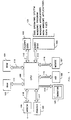
- Fig. 1 is a very general block diagram of an IBM compatible personal computer (PC) which supports the Microsoft WINDOWS graphical environment, and, in turn, WINDOWS supports my form system which is described herein.
- PC personal computer
- the central processing unit (CPU) 100 typically employs a processor of the IntelTM family of microprocessors.
- the read only memory (ROM) 101 contains the basic input output system code (BIOS) for addressing and controlling floppy disk 103, hard disk 104 and printer 108.
- Random access memory (RAM) 102 is the working memory for CPU 100. In a typical WINDOWS installation, RAM of two megabytes or more is employed.
- Monitor 105 of Fig. 1 provides a visual display; keyboard (KB) 106 and mouse 107 provide for manual input to any process running on the PC.
- Printer 108 creates hard copy images of output of the PC; and modem 109 provides communication between the PC of Fig. 1 and other computers.
- hard disk 104 is illustrated as containing a body of program and data information 121. Included in this body of information is a disk operating system (DOS), the WINDOWS graphical environment system software; user application programs which operate under the WINDOWS environment; user application programs which do not employ the WINDOWS environment facilities; and data files of all sorts.
- DOS disk operating system
- WINDOWS graphical environment system software the WINDOWS graphical environment system software
- user application programs which operate under the WINDOWS environment
- user application programs which do not employ the WINDOWS environment facilities
- data files of all sorts are included in this body of information.
- Fig. 2 illustrates, in a general way, the interaction and flow of information between the illustrated software entities.
- Non-WINDOWS application programs 201-1 through 201-M are served by the CPU 100 operating under Microsoft Corporation MS DOS system 206.
- Paths 210, 211 are symbolic paths and are not intended to represent physical paths.
- the MS DOS operating system 206 employs MS DOS software device drivers to control the disks 221 and printers 222 through the facilities of ROM BIOS 209.
- MS DOS device drivers also control system communication with the display monitor, an RS232 port, a keyboard, a modem and a mouse.
- WINDOWS application programs 203-1 through 203-N are served by WINDOWS graphical environment software 205.
- the windows software comprises: User, graphical device interface (GDI) and Kernel modules.
- Symbolic communication paths 212 and 213 pass function calls to WINDOWS software 205 and responses to the respective WINDOWS application software.
- WINDOWS device drivers 208 are the counterpart of MS DOS device drivers 207 and serve the same functions.
- box 300 represents the major software modules of my form system.
- my form system comprises two modes of operation, namely "form creation” and "run time” form completion.
- Form creation comprises four phases:
- the four tool modules, 301 through 304 serve in the implementation of phases 1 through 4 referenced above herein.
- Tool modules 301 through 304 are not available in my run time form completion mode of operation.
- Memory manager module 305 manages the assignment of memory space. This module performs common functions for the other modules relating to the allocation and deallocation of portions of memory to contain data structures. It does this by allocating large portions of memory from Windows and dividing these into smaller portions as needed by the other modules.
- the memory manager also maintains a list of names used for forms, fields, system functions, and links (called a symbol table) so that the portion of memory associated with these items can be located and referenced by its name.
- Form execution module 306 and tree execution module 307 serve in implementation of my goal oriented form completion mode of operation. These modules are also available for use in conjunction with tools 301 through 304 during form creation.
- Link manager module 308 implements reading and writing communication with the extrinsic data sources and destinations defined during form creation.
- File I-O subsystem module 309 controls the transfer and the form of data as it is moved between the hard disk and the RAM main memory of the PC.
- WINDOWS interface module 310 provides communication between my form system and the WINDOWS graphical environment software.
- Fig. 4 represents the major divisions of my "form image data file" which is generated during form creation and is maintained in disk memory. A detailed description of the "form image data file” of Fig. 4 is included herein as Appendix A which appears immediately before the Claims.
- File I-O Subsystem module 309 transfers a form image data file between main memory and the hard disk for storage and retrieval in the course of creation and completion of the form defined by the file.
- the image file stored in main memory and the corresponding image file stored in a hard disk contain the same data; however, the file in main memory is a binary representation of the image data, and the file in hard disk is an ASCII representation of the numerical and text portions of the image data.
- File I-O Subsystem module 309 makes the conversions during transfer of an image file.
- my form system analyzes the data therein and constructs a symbol table, a set of memory structures which correspond to each record in the data file (forms, form objects, fields, tree objects, and links), and "linked lists" which represent dependencies between the various form system components.
- the symbol table is a list of all names used in the form and the memory location of the records of that list.
- the linked list is required to determine the proper order for goal oriented prompting through the collection of forms.
- the linked list represents the data dependencies which are inherent in the decision tree definitions contained within the data file. These dependencies must be comprehended by the tree execution module when performing calculations or when determining the next field value to prompt for.
- Figs. 5 through 8 illustrate various window presentations and pull down menu commands which may be encountered in the use of my form system.
- Fig. 5 is an opening window which is displayed prior to selection of a form application.
- the menu items shown in the main body of Fig. 5 are displayed on a mutually exclusive basis when the corresponding menu items, File, Edit, etc. are selected. Since this is the first window described herein, the features which are derived directly from the Microsoft WINDOWS environment are provided as background to the later description of my form system.
- WINDOWS software, such as my form system software, is called an application program.
- application as used in WINDOWS must be distinguished from forms by which an individual makes an "application” e.g., for credit approval.
- application the WINDOWS definition of the term "application” in mind, the WINDOWS environment provides for two general types of windows, namely, "application” windows which contain currently running application software and "document” windows which appear with application software that can display two or more windows simultaneously.
- Document windows share the application window's menu bar. Commands that affect an application window affect the document as well. Document windows have their own title bar unless their physical size is maximized to fill the screen. In the latter case the document window and the application window share a title bar.
- Fig. 5 illustrates the opening window of my form system application program.
- the small rectangle in the upper left corner of the window of Fig. 5 represents the window control menu box which is found on all windows of the WINDOWS environment.
- the pull down menu for the control menu box of Fig. 5 is shown under that heading in the working area of the window.
- the menu for the control menu box and the main menu items are shown for purposes of discussion only. These menus are displayed only after a main menu command has been selected.
- control menu commands permit an individual to: size, move, maximize, minimize and close windows; and to switch to WINDOWS Task List from a keyboard or by use of a mouse.
- the horizontal area to the right of the control menu box in Fig. 5 is the title bar which designates an application program e.g., Form System as shown in Fig. 5; and the title of the current active files under the named application program.
- the down and up arrows on the right side of the title bar are employed respectively to decrease and increase the size of the window.
- the pull down menu commands for the opening window are tailored to my form system.
- the commands which are then available for execution are presented in a bold black type style; and the commands which are not available for execution are displayed in a readable, but somewhat obscured print style.
- my form system has two modes of operation, namely, form creation and run time form completion.
- form creation follows a description of run time form completion. This order of presentation is adopted because the description of a previously created form provides valuable insights into my goal oriented forms, and to the decision trees, links and form stack relations embodied therein.
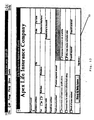
- a set of four forms for making application for life insurance are displayed in Figs. 9 through 12.
- the data file containing the life insurance forms is entitled Life.DF.
- Fig. 5 an operator selects the "Open" command from the "File” menu.
- my form system provides a list of form files, including Life.DF, which are available for selection. A selection is made by highlighting the file to be selected and either clicking the mouse or striking the RETURN (or ENTER) key on the keyboard.
- a form file e.g., Life.DF
- a screen essentially as shown in Fig. 13 is presented to an operator for completion.
- the form shown in the window of Fig. 13 is also shown in Fig. 9.
- a goal form e.g., the Life Insurance Application form is presented as shown in Fig. 13, the first field to be completed, Proposed Insured is outlined in a heavy line and a large "I" shaped cursor is presented in that field.
- Information input to a prompted field may comprise: typed information followed by depression of the RETURN key of the keyboard; or may comprise selection by use of a mouse or by use of the ARROW and RETURN keys of the keyboard.
- my system In order to implement goal oriented prompting, my system first determines which form is the goal form. When an application is initially loaded into memory, the top form of the stack is selected as the goal form. Later, an operator can use the "Select" command on the "Form” menu to select another form to become the goal form.
- my form system selects the first field without a value on that form as the goal field. It does this by searching down the linked list of field objects on the form until it finds a field that does not currently have a value.
- my system next determines which field, if any, is dependent on the goal field. This is done by looking at any decision trees which are associated with the field to determine which field in the decision tree is next needed to complete the tree. This is done by starting at the base of the tree and following all selected branches of the tree until my system detects either a branch node that does not have a value, a condition expression that does not have a value, or a conclusion expression that does not have a value. This field, if any, becomes the dependent field which my form system must prompt for next.
- the system next locates any form that contains this field. Starting at the top of the stack, my form system looks at each form in turn to find which form closest to the top of the stack contains that field. My form system then moves that form to the top of the stack so that the user can enter a value. If the field is not found on any form, my system prompts for the field on a special "scratchpad" form.
- Fig. 14 shows the display after the Premium Calculation form has been automatically moved to the top of the stack to prompt for "Amount of basic policy". This was done because my system determined that "Amount of basic policy” was the next dependent field necessary to calculate a value for the "Total Annual Premium” field on the Life Insurance Application form, which was the goal form. Since the Premium Calculation form was moved to the top of the stack temporarily due to my goal oriented prompting, it is identified as as prompt form by displaying the word "prompt" after the title of the form as shown in Fig. 14. This form will also be automatically removed from the display once the operator enters values for the dependent fields on it.
- an operator can use the "Close" command on a prompt form's control menu to close the form at any time. When the operator does this, my system moves to the next field on the current goal form and proceeds with the goal oriented prompting for its dependent fields, if any.
- An operator can also cause my system to pursue goal oriented prompting for any field of his or her choice by first selecting the field, then using the "Calculate” command on the "Field” menu. This causes my system to make the selected field the goal field for purposes of goal oriented prompting.
- My system looks and determines which forms, if any, contain the field and displays the new value on each of those forms. If the goal form, which the system selected in its goal oriented prompting, now has a value for the field which was originally the goal field, or if the operator did not enter a value for the prompted field but rather answered a value for a different field, or if the operator pressed the Tab Key, then the goal form is advanced to the next field and the goal oriented prompting sequence starts over again for that field.
- My form system also maintains any dependencies related to external sources of data that have been linked to the forms.
- my system automatically locates the appropriate record and updates the values of any fields linked to the database.
- my system automatically notifies the other application of the change.
- my system Upon entry of a value for any field, my system automatically prompts for entry into the next field according to the goal sequence defined above. As values are entered into the prompted fields, automatic prompting may continue on the initial goal form to completion of that form; or dependent on the values entered in certain fields, prompting may digress to a subsidiary form of the stack. In any event, form fields which receive their data from linked data sources or by calculation are not visited by the prompting cursor.
- the outline of the field is a distinctive dotted border to advise that the operator is not expected to provide an answer.
- the fields: "Proposed insured”, “Beneficiary name”, “Beneficiary address”, etc. are all fields for which the operator is prompted for an answer.
- the fields: "Total Annual premium”, “Premium payment amount”; and "Deposit required” are fields which receive their values by calculations.
- Fig. 15 illustrates the ability of the system of my invention to highlight the selected path in a tree for the user.
- the tree for "premium payment amount" is currently determined by the value first for the insured not meeting the basic requirements being “no” and the mode of payment being "monthly” with a thicker line for that selected path and then the calculation corresponding to monthly mode of payment is the expression which is used to calculate the premium payment amount.
- Fig. 15 Also of note in Fig. 15 is the use of different icons in the decision tree display to distinguish calculated fields.
- the leftmost branch object includes a decision tree icon above the branch field; in this case "Insured does not meet basic”. This decision tree icon indicates that the value of "Insured does not meet basic” is calculated via a decision tree rather than being entered by the operator.
- the other branch object for "Mode of payment”, does not have this icon. "Mode of payment” is a field which the operator must enter.
- This display technique highlights the capability of my invention to embed arbitrarily complex computations which result in a value for a field within a single branch object.
- Fig. 16 is the capability of my invention to indicate that a value for a field has been entered by the user overriding the value that would be brought to that field from the tree.
- the field called "Premium Payment Amount" has been entered as $150.00 by the operator and the cross/hatching over that field indicates that this value was entered by the operator rather than by the tree that is available for that correct determination of the premium payment amount.
- Form creation in my invention involves the use of four interrelated tools.
- the form tool the stack tool, the tree tool, and the link tool. These will be discussed individually in the following paragraphs.
- the form tool of my system is a facility for creating and modifying application forms.
- the form tool provides a high level, graphical method for defining forms. It operates much like a drawing package and displays forms as they are being defined.
- the physical size of a region can be selectively set; and a region can have a border on any or all sides.
- the width of a region must be an integral multiple of the pitch of the default font employed in a form; and the height of a region must be an integral multiple of the height of the default font.
- the borders for adjacent regions are shared.
- Form objects fall into two general classes, namely, static and dynamic. Regions which are assigned static form objects are not involved in my goal oriented prompting.
- the static form objects are: text, graphics, filled rectangles, rounded rectangles and lines.
- Fig. 13 There are three static form object regions in the illustrative insurance application of Fig. 13.
- the large title region with the text "Apex Life Insurance Company” and the signature region at the bottom of the form of Fig. 13 are both text form objects.
- the title region illustrates the use of text font type and size which are different from the default text.
- the region to the right of the region named "Premium payment amount" is a filled rectangle form object.
- FIG. 13 The remaining regions of the form of Fig. 13 are field form objects which are for ease of reference termed "fields" herein. Fields are employed to display: (a) data entered by a user; (b) data calculated by my form system; or (c) data provided by a link to an external source.
- All form objects have assigned "properties" which define: size, appearance, and functions attributable to an object.
- all form objects may be assigned a border property; and this is the only property which can be assigned to filled rectangle or graphics objects. Font and alignment properties, also, can be assigned to text objects.
- form creation begins with use of the Form Tool of my system.
- the operator invokes the Form tool by using the "Form” command on the "Tools” menu shown in Fig. 5.
- the form tool provides the following capabilities: (a) creation of a new form; (b) adding new objects to a form; (c) renaming, sizing and scrolling forms; (d) finding forms that contain a specified field; (e) selecting, moving and sizing form objects; (f) editing form objects with the clipboard; (g) changing the field referenced by a field object; (h) changing the names of field and text objects; (i) adding help text to be displayed for a field object; (j) changing the display format of a field object; (k) changing the alignment of text within field objects and text objects; (1) changing the character fonts of text objects and field objects; (m) controlling which, if any, borders are drawn around objects; (n) controlling whether the field name is displayed in a field object; and (o) protecting field objects both from override by the operator or display of the tree associated with the field object.
- Fig. 17 shows the dialog box for attaching context sensitive help to a field using the "Help" command on the "Properties” menu in Fig. 6.
- the help for the field called "Proposed Insured” is an elaboration of some information that may be of value to the operator filling out the form.
- Fig. 18 and 19 illustrate an automatic feature provided in the form tool that places check boxes within the space allotted to a field.
- a vertical space is alloted a field called "Mode of Payment" and the check boxes are displayed accordingly.
- Fig. 19 a horizontal field is provided for mode of payment and the check boxes are arranged accordingly.
- Fig. 20 shows the case where insufficient space is allocated for "mode of payment” and although check boxes are indicated, the system automatically provides a selection list since there is insufficient room for the check boxes. There is always room for the selection list since even as the list grows, scroll bars can be added to the display and an arbitrarily long list can be shown.
- Fig. 21 shows a dialog box that allows for the automatic generation of the values for fields.
- This dialog box appears whenever the operator changes the type of a field to either "selection list” or “check box” using the "Field Type” command on the "Properties” menu shown in Fig. 6.
- the automatic determination of the values looks at values that can be attached from the tree, values that are used in a tree which employs the field for determination of the other tree's value, or finally automatic creation of the values by looking at the values that can be brought from the records of a database. If automatic is not selected, then the new values are manually entered in the edit box under "New Value” and then added to the list in the box called "Values".
- FIG. 22 shows the dialog box that can be used to disallow override values using the "Protection" command on the "Properties" menu shown in Fig. 6.
- the meaning of no override is that the user is not allowed to override a value which has been assigned to the field from a tree or from a database reference.
- Field protection can also block the ability for the user of the application to observe the decision tree logic for a particular field. Both of these protections are done on a field-by-field basis.
- the Stack Tool which provides for manipulation of the forms of an application, is a high-level, graphical facility for copying, creating, deleting and arranging forms.
- the stack tool there are specific capabilities that allow application creators to create new forms, change the title of an existing form or change the order of the existing forms within an application. For instance, it is often useful to change the order of forms to move a new form to the top of the stack so that it becomes the goal form when the application is initially loaded into memory.
- Fig. 23 depicts a window which is displayed when the stack tool is chosen using the "Stack" command on the "Tools” menu. It shows the four related forms that comprise the "stack" or set of forms for this application.
- the stack for the file Life.DF comprises the goal form and three subsidiary related forms.
- the top form of the stack in this case the Life Insurance Application form, is depicted as a goal form through the use of a special icon for the top-most form in the stack.
- Tree Tool another specialized tool called the Tree Tool is provided in order to create and modify decision trees.
- the Tree Tool is invoked by the operator by first selecting the field associated with the tree and then using the "Tree" command on the "Tools" menu as shown in Fig. 5 and Fig. 6.
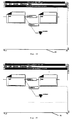
- the first object is the branch object which is shown in Fig. 24 highlighted with a broken line.
- the branch object consists of a condition of the preceding field; in this case, Field 1.
- the first condition of Field 1, condition 1A is the condition leading to the highlighted object.
- the second part of the branch object is the field upon which the new branch will be taken; in this case, Field 2.
- Fig. 25 illustrates the conclusion object.
- the conclusion object is highlighted with a broken line.
- the conclusion object consists of a condition that the preceding field, again in this case Field 1.
- the second condition of Field 1, condition 1B is the condition of this object.
- the second part of the conclusion object is the conclusion itself; in this case, just indicated with the word "Conclusion”.
- Conclusions can be text, fields, functions, or combinations of the proceeding in expressions connected with operators using spreadsheet syntax.
- Fig. 26 shows multiple branches from an example field called "Mode of Payment". If mode of payment is "annual", the value for the premium payment amount is the "total annual premium” as indicated in the conclusion for that branch. If the payments are made “semi-annually", the expression uses the function @ROUND of the total annual premium multiplied times the factor that it adjusts it for the fact that there are two payments made during the year (each equal to about one-half or 0.515 of the annual amount). The @ROUND function also requires specification of the number of decimal places. In this example, the value set at two places gives a dollar and cents amount.
- My system provides a complete set of built-in functions, such as @ROUND, which can be used within tree conditions and conclusions to calculate values based on field values. These functions are listed in Appendix A under the heading "IDFunction”.
- a dialog box like that shown in Fig. 27 is displayed as a part of the specification of both conditions and conclusions.
- This dialog box appears when the operator selects either the "Condition” or “Conclusion” command on the "Properties” menu shown in Fig. 7.
- the condition or conclusion expression is contained within the edit window in the upper part of the box.
- Fig. 28 shows a portion of the list of functions available in alphabetical order including an option to paste in descriptive arguments for the functions.
- Fig. 29 shows the dialog box allowing the pasting of fields. This is simply a listing of all of the fields currently defined in the application thereby saving a number of keystrokes for the choice of a field from the list of all possible fields available.
- My invention also provides a very innovative approach to the display of arbitrarily large trees in a fixed-size region, such as on a computer display.
- Figures 30 and 31 both display the same decision tree but at two different levels of magnification.
- Fig. 30 shows a larger view than that shown in Fig. 31.
- the fields, the branches, the conclusions are arranged with spacing to maximize the amount of information displayed. If a more magnified view is selected, like that of Fig. 31, the branches and conclusions are rearranged with closer spacing in order to fill in some of the blank space that would be available if the prior spatial arrangement of Fig. 30 were maintained.
- my system To maximize the display of tree objects on a fixed size display, my system first determines how many tree objects to display in one horizontal row of the display. The operator can control the number of tree objects displayed in a horizontal row by using the "Expand” command on the "View” menu to decrease the number of tree objects or the “Reduce” command on the "View” menu to increase the number of tree objects.
- my system next determines the number of tree objects that can be displayed in a vertical column while maintaining the proper aspect ratio of tree objects. My system then displays one horizontal row of tree objects at a time without displaying any objects that are beyond the rightmost edge of the display. Any horizontal rows which contain only tree objects beyond the rightmost edge of the display are not displayed. The result of eliminating these rows is that the display surface is more densely packed with at least one tree object in each horizontal row. This eliminates much of the "white space” that would occur when displaying portions of a large tree near the root of the tree.
- Fig. 32 illustrates the use of a tree that has as one of its possible conclusions the value of the field for which the tree is being determined.
- the ability of a tree for a particular field to reference itself is useful in providing the user of the system with values determined by the tree if the tree has anticipated the values of interest. But in the case where the values have not been anticipated by the tree, the self-reference allows the field to be prompted so that the operator can enter the information directly.
- the Links Tool provides an ability to relate the fields on the form system with the fields in related database(s).
- Fig. 33 shows the dialog box for establishing both read and write links between applications and the databases.
- the Links Tool dialog can be entered from either form completion mode or from the Form Tool by using the "Links" command on the "Tools" menu.
- Fig. 33 allows the operator to associate database fields (listed on the left side of the dialog box) with fields defined within my form system. This association can be made for both the purpose of reading data from the database and writing data into the database.
- Fig. 33 is from the Life Insurance Application example used earlier and shows how an applicant's address, city, state, etc. can be obtained from a database given the applicant's name.
- Fig. 34 shows the ability of my invention to take care of a case where there is not an established database in place corresponding to the values of the fields within my forms system.
- a link named "New Link” has been attempted with a database; in this case, a database table named "New File”.
- the system was unable to open that file because that file did not exist and the option provided in the dialog box allows the operator to create a new database table with this name.
- My system uses the properties of the fields as defined by the operator to create database fields of the appropriate size and type.
- the following is the file format in which my graphical image data file for documents are saved on disk.
- the file is a binary file and can be considered to be a sequence of variable length chunks of data called records. Each record begins with a 2-byte ID data byte followed by 4 bytes define the length of the remainder of the record. The last record of a file is an EOF record.
- Character data and numeric data are in ASCII format.
- the only record that contains environment specific information is the FORMPICTURE record. Because an implementation can ignore records with a u2PictureFormat that it does not recognize, picture definitions for multiple environments can coexist, i.e., a file can contain both a Macintosh and a MS Windows version of a picture and as a result be run on either system.
- the name of each data element implies its format on disk.
- the name u2DummyData based on its prefix (u2), is a 2 byte unsigned integer with the least significant byte first.
- Other prefixes are defined in Table 1: Name Prefix Definitions. If a name has no prefix (has in initial capital) it is a complex structure or sequence defined elsewhere.
- a series of property definitions is a little like a series of records in which the last property definition is the EOP property, b) the length of a property is implied by its type instead of being specifically declared, and c) the property type is 1 byte long instead of 2.
- NOTITLE property - don't display title (type 1) This property has no data associated with it.
- NOTREESHOW property - don't show tree to user (type 3) This property has no data associated with it.
- the default is to display all borders.
- Data is a type byte followed by a variable-length value.
- Logical and error values are 1 byte long.
- Text and numeric values are in "sv" format.
- Object code is a sequence of tokens in Reverse Polish order. Some tokens, such as OP_PLUS, are one-bytes tokens; some, such as OPERAND_NAME, have fixed-length information that follows; others, such as OPERAND_TEXT, are followed by variable length data. The data tokens are the same as data objects defined in the section Variable Length Data. Function ID's are listed in Table 5: Function ID's.
Abstract
Description
- This invention relates to a programmable controlled, goal oriented electronic system for form creation and form completion according to the preamble of
claim 1. - Forms to gather data are employed daily in almost every commercial activity, in schools, and in all levels of government activity. It is a rare occurrence that an individuals life is not frequently touched by many forms. In the past, forms have been prepared by many processes ranging from hand and typewriter printed forms to engraved and mass produced forms. Prior to the advent of pervasive computing facilities, forms were completed by hand or by a typewriter and were generally interpreted by an individual. Today, there are many software packages which are capable of creating very fine printed forms. The recent proliferation of "Desk top publishing" software and of laser and inkjet printers has brought creation of good printed forms within the reach of individuals with high end personal computers as well as businesses.
- Today, many electronic forms are completed by individuals using a keyboard and/or a mouse or other pointing device; the data thus gathered is possibly stored for later reference; and a report is printed for an immediate purpose. In prior art systems known to me, to the extent that forms provide prompting of fields to be completed, the fields are presented in sequence without regard for the data entered in the course of completing the form. If a form is extensive, there may be prompting for information which is not relevant in the context of the answers which have been entered. This is wasteful of operator time since unnecessary information is often requested.
- In the prior art, in order to avoid prompting for unnecessary information, a first limited form is often presented for completion; the entries on that form are evaluated by an individual; and a decision is made to require completion of one or more additional forms. Since there is no automatic prompting for completion of additional forms which are dictated by answers on the completed form, the operator is unduly burdened with the decision process; and operator time is wasted.
- Forms are often used to describe and organize a complex decision process or "business policy". As such, the form contains blanks for both the inputs and results of the decision process. However, the form itself it typically very poor at describing the decision process other than by including notes in the margins. For this reason, many forms are accompanied by an instruction sheet, or "policy manual", which the operator must read, interpret, and apply in the process of completing the form. This is wasteful of operator time, makes it harder to disseminate new decision processes, and results in many forms being completed incorrectly. This weakness of paper forms is not effectively addressed by current form software packages.
- In "High Level Form Definition in Office Information Systems", The Computer Journal, Vol. 26, No. 1, pages 52-59, N.H. Gehani proposed a high level form definition language. The form definition language proposed is modeled after a procedural programming language. In "FORMS DEFINITION METHODS", 5th Annual International Conference on Computers and Communications 1986, pages 708-712 another form definition language is described by M. Butterworth. The form definition described is a procedural language in its use of subforms. However, both form definition languages are unintuitive, and therefore ill-suited for use by non-programmers. Form creation by means of such form definition languages need programmers, which are trained in procedural programming language, but is not suitable such as for office workers.
- The invention, characterized in
claim 1, is based on the problem to provide a goal oriented electronic system for form creation, form completion and using form data files which define:
(a) a graphical image of a goal oriented form for display on a monitor; and (b) a graphical image of at least one decision tree comprised of branches and conclusions which are discretely associated with fields of the form and which define logical and/or mathematical operations which implement goal oriented prompting within a form and among forms of a set of forms. - Further, in accordance with my invention, my system for generating form data files defines: (c) reading and writing links between fields of the form and a variety of data sources and destinations; and (d) other forms which, with the subject form, comprise a related set or "stack" of forms.
- Provision of such inventive goal oriented electronic system which includes a graphical image of at least one decision tree defining these operations and provision of tools for modifying the graphical image of at least one decision tree ensure, that also non-programmers can create and complete interactive forms easily and quickly.
- For purpose of clarification, a "goal oriented" electronic form is one in which the prompts for answers generally flow through the form from left to right; and from top to bottom of the form; and the ongoing pattern of prompting is conditioned on answers provided to the form or on data obtained from referenced sources. Advantageously, as the answers to the field prompts are entered, fields which need not be answered are skipped, and fields on the same or a linked form are prompted in the desired sequence.
- In the event that an individual completing a report, by choice, revisits a completed field and enters a new value in the field, my form system automatically executes a prompting sequence consistent with that new value, and calculates new values for fields which are dependent on the value in the changed field. Advantageously, it is thus possible to try various "what-if" scenarios. This feature of my system is termed "truth maintenance" since only valid and necessary prompting is implemented; and all calculated results are consistent with the values in the completed fields of a form.
- In accordance with my invention, my system provides a set of intuitive "creation" tools which readily permit creation of the above referenced form files. In an illustrative embodiment of my invention, form creation is divided into four natural selectively reentrant activities: an initial specification of the fields of a form to be created; specification of the tree branches and conclusions to implement the intended logical and mathematical relations of the form; specification of reading and writing links to selected data files; and specification of relations between forms to define a stack of related interdependent forms.
- Advantageously, these activities can be performed in any desired order; and each activity can be reentered selectively to make additions and/or corrections in order to accommodate thoughts which occur in the course of form creation.
- Furthermore, at any point in the process of form file creation, it is possible to selectively display: the current form; any selected part or all of the related tree structure; links to data sources and destinations; and the contents of a stack and the order of the contents in the stack.
- In accordance with my invention, if during the course of creating a form, an expression assigned to a branch or conclusion references a form field which does not exist, my system automatically creates a new field which adopts the established name. Subsequently, a field may be placed on the form to hold that name; however, if no field is assigned on the form, my system automatically prompts for a value at the appropriate place during the completion of the form. The prompt for such a field presents a prompt window that requests selection of a value for the question that does not appear on the form; however, a value is required for that field since continued prompting in the form is dependent on the value selected.
- In accordance with my invention, if during the course of creating a form, links are requested to a data base which does not exist, my system automatically creates a new data base with fields, which adopt the established names and characteristics of the fields contained in the form system.
- In accordance with my invention, "help" information may be assigned to a field during form creation; and that help information is available to an operator during form completion.
- In accordance with my invention, I provide "run time" software for operator completion, but not alteration, of previously created forms. My "run time" software permits an operator to selectively view the trees associated with a form being completed to provide an understanding of the logical and mathematical relations and processes embodied in the form. Advantageously, my graphical tree displays identify "active" and "inactive" tree branches in accordance with data gathered in the form prior to display of the tree.
- Advantageously, my form system automatically reformats horizontal segments of a graphical display of a tree that covers two or more horizontal segments and two or more vertical screens in order to minimize the number of vertical screen displays required to show the entire horizontal segment.
- Advantageously, my system may be used to both create and complete goal oriented forms to implement inquiries in any situation in which the relations and functions of the fields of a form can be described by a tree of branches and conclusions.
- Although my forms provide goal oriented prompting, an operator may choose to depart from the suggested order of form completion. In accordance with my invention I provide a "resume" function which may be manually selected to return to goal oriented prompting for further answers required to complete a form.
- During completion of a form, a field may require selection of a value from a defined set of values. The list of values, from which a selection is to be made, may be created manually during form creation; or may be derived from tree statements which: (a) are attached to the field and create answers which correspond to the selections in the list; (b) rely upon selection of a value from the list to complete evaluation of an expression; or (c) are established by a link to a database which provides values contained therein.
- In the course of form creation, the display of fields which require selection of a value from a set of values, as a design choice, may be defined as "selection list" fields or "check box" fields.
- In the case of a "selection list" field, a dialog window with a list of values is presented for selection of a value when the corresponding field is prompted for an answer. A selection is made by moving a cursor over the desired item and clicking the mouse or depressing the return key.
- In the case of a "check box" field, each value of the list is displayed with a small box for placing a check mark. In accordance with my invention, my form system automatically generates a field object which contains a number of selection boxes equal to the number of possible selections. Advantageously, my system automatically arranges the display of the set of selection boxes to match the size and shape of the field on the form. If the allotted field space is too small to accommodate all of the check boxes and their name text, the field is automatically defaulted to a "selection list" field.
- In accordance with my invention, keyboard entries are checked against "field characteristics" which are assigned to a field during form creation. If a keyboard entry for a field is not consistent with the assigned characteristic, the entered value is rejected and an error message advises the operator of a problem. Such characteristics can be assigned to a field by standard "picture" specifications. Alternatively, requirements for the form of a field input can be established by local form rules which are implemented by decision trees attached to the field. As an option, upon the occurrence of an error in input format, the field in error can be cleared and the prompt returned to that field to continue form completion.
- In accordance with an aspect of my invention fields of a form may be designated as "protected" or "unprotected" at the time a form is created. Values cannot be entered manually in a "protected" field since only the values calculated for the field are considered valid. Even though a value may be automatically calculated for an "unprotected" field, a value may be entered into the field manually to handle exceptional conditions. Fields with this characteristic are termed "over ride" fields. Advantageously, in accordance with my invention, my system clearly marks or flags both the display and printing of fields which contain over ride values.
- Fig. 1 is a block diagram of a personal computer
- Fig. 2 is an overview of software employed in the personal computer of Fig. 1;
- Fig. 3 is a general view of the major elements of my goal oriented form software;
- Fig. 4 is a general view of a form image data file;
- Fig. 5 illustrates an opening window of my form system application program and the menu commands available;
- Fig. 6 illustrates a Form Tool window and the menu commands available;
- Fig. 7 illustrates a Tree Tool window and the menu commands available;
- Fig. 8 illustrates a Stack Tool window and the menu commands available;
- Fig. 9 is the first form in a set of four forms for an application for life insurance example;
- Fig. 10 is the four forms for an application for life insurance example;
- Fig. 11 is the third form in a set of four forms for an application for life insurance example;
- Fig. 12 is the fourth form in a set of four forms for an application for life insurance example;
- Fig. 13 illustrates a window with a "goal" life insurance application for completion or modification;
- Fig. 14 illustrates the display of a second form for prompting of values necessary for completion of a goal form;
- Fig. 15 illustrates the highlighting of the selected path in a tree;
- Fig. 16 illustrates the indication that a value for a field on a form has been overridden by a user;
- Fig. 17 is the dialog box for attaching context sensitive help to a field;
- Fig. 18 illustrates the automatic arrangement of check boxes in a vertical region;
- Fig. 19 illustrates the automatic arrangement of check boxes in a horizontal region;
- Fig. 20 illustrates the automatic presentation of a selection list when insufficient space is provided in a region for check boxes;
- Fig. 21 is a dialog box for automatically or non-automatically specifying values expected for a field;
- Fig. 22 is a dialog box for specifying field protection;
- Fig. 23 illustrates a stack tool window with a display of related forms;
- Fig. 24 is a display of a branch object in a tree;
- Fig. 25 is a display of a conclusion object in a tree;
- Fig. 26 illustrates multiple branches and expressions for calculating results for each branch;
- Fig. 27 is a dialog box for specifying conditions and conclusions in a tree;
- Fig. 28 is a dialog box for pasting functions into an expression;
- Fig. 29 is a dialog box for pasting field names into an expression;
- Fig. 30 illustrates a larger perspective view of a tree shown in Fig. 31.
- Fig. 31 illustrates a more detailed view of a portion of the tree in Fig. 30.
- Fig. 32 illustrates a self-referencing tree;
- Fig. 33 is a dialog box for establishing links between fields in the form system and fields in related database(s);
- Fig. 34 is a dialog box for selecting the option to create a new database file when there is no established file.
- The illustrative embodiment of my invention is disclosed as an application program running under Microsoft WINDOWS™ graphical environment program on an IBM compatible PC.
- Notwithstanding, disclosure of my invention in this particular environment, the principles of my invention can be implemented as a program which includes an integral interface facility; or in the context of other interface environments.
- Although the graphical images and protocols employed by my form system are generally driven by the WINDOWS environment, my system includes menu features which are not present in or contemplated by WINDOWS. The general features, functions and protocol of WINDOWS are described later herein with the introduction of the opening window of Fig. 5.
- Fig. 1 is a very general block diagram of an IBM compatible personal computer (PC) which supports the Microsoft WINDOWS graphical environment, and, in turn, WINDOWS supports my form system which is described herein.
- The central processing unit (CPU) 100 typically employs a processor of the Intel™ family of microprocessors. The read only memory (ROM) 101 contains the basic input output system code (BIOS) for addressing and controlling
floppy disk 103,hard disk 104 andprinter 108. Random access memory (RAM) 102 is the working memory forCPU 100. In a typical WINDOWS installation, RAM of two megabytes or more is employed. -
Monitor 105 of Fig. 1 provides a visual display; keyboard (KB) 106 andmouse 107 provide for manual input to any process running on the PC.Printer 108 creates hard copy images of output of the PC; andmodem 109 provides communication between the PC of Fig. 1 and other computers. - In Fig. 1,
hard disk 104 is illustrated as containing a body of program anddata information 121. Included in this body of information is a disk operating system (DOS), the WINDOWS graphical environment system software; user application programs which operate under the WINDOWS environment; user application programs which do not employ the WINDOWS environment facilities; and data files of all sorts. - Fig. 2 illustrates, in a general way, the interaction and flow of information between the illustrated software entities.
- Non-WINDOWS application programs 201-1 through 201-M are served by the
CPU 100 operating under Microsoft CorporationMS DOS system 206. Programs and data flow between Non-WINDOWS applications 201-1 through 201-M andMS DOS 206 via paths labeled e.g., 210, 211.Paths - The MS
DOS operating system 206 employs MS DOS software device drivers to control thedisks 221 andprinters 222 through the facilities ofROM BIOS 209. MS DOS device drivers also control system communication with the display monitor, an RS232 port, a keyboard, a modem and a mouse. - WINDOWS application programs 203-1 through 203-N are served by WINDOWS
graphical environment software 205. The windows software comprises: User, graphical device interface (GDI) and Kernel modules.Symbolic communication paths WINDOWS software 205 and responses to the respective WINDOWS application software. -
WINDOWS device drivers 208 are the counterpart of MSDOS device drivers 207 and serve the same functions. - In Fig. 3,
box 300 represents the major software modules of my form system. In accordance with my invention my form system comprises two modes of operation, namely "form creation" and "run time" form completion. Form creation comprises four phases: - (1) Definition of: a form image for all forms of an application, names of fields of the form or forms, and field characteristics;
- (2) Definition of the forms of a related set i.e., a "stack" of forms and the assigned order of the forms in the set. When a form set is opened for completion, the defined order establishes which form of a set is the initial "goal" form, and the order in which the other forms of the set are presented for completion;
- (3) Definition of decision tree structures comprising branches and conclusions which are assigned to the fields of the forms which comprise a related stack of forms; and
- (4) Definition of reading and writing links between fields of a form and extrinsic data sources and destinations.
- The four tool modules, 301 through 304 serve in the implementation of
phases 1 through 4 referenced above herein.Tool modules 301 through 304 are not available in my run time form completion mode of operation. -
Memory manager module 305 manages the assignment of memory space. This module performs common functions for the other modules relating to the allocation and deallocation of portions of memory to contain data structures. It does this by allocating large portions of memory from Windows and dividing these into smaller portions as needed by the other modules. The memory manager also maintains a list of names used for forms, fields, system functions, and links (called a symbol table) so that the portion of memory associated with these items can be located and referenced by its name. -
Form execution module 306 andtree execution module 307 serve in implementation of my goal oriented form completion mode of operation. These modules are also available for use in conjunction withtools 301 through 304 during form creation. -
Link manager module 308 implements reading and writing communication with the extrinsic data sources and destinations defined during form creation. - File
I-O subsystem module 309, among other functions, controls the transfer and the form of data as it is moved between the hard disk and the RAM main memory of the PC. -
WINDOWS interface module 310 provides communication between my form system and the WINDOWS graphical environment software. - Fig. 4 represents the major divisions of my "form image data file" which is generated during form creation and is maintained in disk memory. A detailed description of the "form image data file" of Fig. 4 is included herein as Appendix A which appears immediately before the Claims.
- File
I-O Subsystem module 309 transfers a form image data file between main memory and the hard disk for storage and retrieval in the course of creation and completion of the form defined by the file. The image file stored in main memory and the corresponding image file stored in a hard disk contain the same data; however, the file in main memory is a binary representation of the image data, and the file in hard disk is an ASCII representation of the numerical and text portions of the image data. FileI-O Subsystem module 309 makes the conversions during transfer of an image file. - At the time that a form image data file is transferred to main memory for editing or completion, my form system analyzes the data therein and constructs a symbol table, a set of memory structures which correspond to each record in the data file (forms, form objects, fields, tree objects, and links), and "linked lists" which represent dependencies between the various form system components. The symbol table is a list of all names used in the form and the memory location of the records of that list.
- The linked list is required to determine the proper order for goal oriented prompting through the collection of forms. The linked list represents the data dependencies which are inherent in the decision tree definitions contained within the data file. These dependencies must be comprehended by the tree execution module when performing calculations or when determining the next field value to prompt for.
- Three types of dependencies must be maintained for proper execution by the tree evaluation module:
- (1) The use of a field as a branch condition within a decision tree. The value of the field must be determined before a branch can be selected.
- (2) The use of a field within a formula that specifies the condition under which a branch should be taken. The value of the field must be determined before the condition can be evaluated.
- (3) The use of a field within a formula that specifies the conclusion value at a terminal branch of a decision tree. The value of the field must be determined before the conclusion can be evaluated.
- All three types of dependencies are constantly maintained in memory using linked lists and are updated as required when additions or modifications are made to decision trees via the tree tool module.
- Figs. 5 through 8 illustrate various window presentations and pull down menu commands which may be encountered in the use of my form system.
- Fig. 5 is an opening window which is displayed prior to selection of a form application. The menu items shown in the main body of Fig. 5 are displayed on a mutually exclusive basis when the corresponding menu items, File, Edit, etc. are selected. Since this is the first window described herein, the features which are derived directly from the Microsoft WINDOWS environment are provided as background to the later description of my form system.
- In the terms of WINDOWS, software, such as my form system software, is called an application program. The term application as used in WINDOWS must be distinguished from forms by which an individual makes an "application" e.g., for credit approval. With the WINDOWS definition of the term "application" in mind, the WINDOWS environment provides for two general types of windows, namely, "application" windows which contain currently running application software and "document" windows which appear with application software that can display two or more windows simultaneously.
- Document windows share the application window's menu bar. Commands that affect an application window affect the document as well. Document windows have their own title bar unless their physical size is maximized to fill the screen. In the latter case the document window and the application window share a title bar.
- Fig. 5 illustrates the opening window of my form system application program. The small rectangle in the upper left corner of the window of Fig. 5 represents the window control menu box which is found on all windows of the WINDOWS environment. The pull down menu for the control menu box of Fig. 5 is shown under that heading in the working area of the window. The menu for the control menu box and the main menu items are shown for purposes of discussion only. These menus are displayed only after a main menu command has been selected.
- The control menu commands permit an individual to: size, move, maximize, minimize and close windows; and to switch to WINDOWS Task List from a keyboard or by use of a mouse.
- The horizontal area to the right of the control menu box in Fig. 5 is the title bar which designates an application program e.g., Form System as shown in Fig. 5; and the title of the current active files under the named application program. The down and up arrows on the right side of the title bar are employed respectively to decrease and increase the size of the window.
- The pull down menu commands for the opening window, as described below herein, are tailored to my form system. When a pull down menu is displayed, the commands which are then available for execution are presented in a bold black type style; and the commands which are not available for execution are displayed in a readable, but somewhat obscured print style.
- For purposes of complete understanding, all of the menu commands of Figures 5 through 8 are described in Appendix B attached hereto.
- As indicated earlier herein, my form system has two modes of operation, namely, form creation and run time form completion. In the following discussion, a description of form creation follows a description of run time form completion. This order of presentation is adopted because the description of a previously created form provides valuable insights into my goal oriented forms, and to the decision trees, links and form stack relations embodied therein.
- For purposes of illustration, a set of four forms for making application for life insurance are displayed in Figs. 9 through 12. The data file containing the life insurance forms is entitled Life.DF.
- When form completion proceeds during a "run time" session of my form system, a subset of menu commands are available to the user. For example, none of the Tools (Forms, Tree, Stack and Link) are available.
- In Fig. 5, an operator selects the "Open" command from the "File" menu. In response to this command, my form system provides a list of form files, including Life.DF, which are available for selection. A selection is made by highlighting the file to be selected and either clicking the mouse or striking the RETURN (or ENTER) key on the keyboard. Following selection of a form file e.g., Life.DF a screen essentially as shown in Fig. 13 is presented to an operator for completion. The form shown in the window of Fig. 13 is also shown in Fig. 9.
- When a goal form e.g., the Life Insurance Application form is presented as shown in Fig. 13, the first field to be completed, Proposed Insured is outlined in a heavy line and a large "I" shaped cursor is presented in that field. Information input to a prompted field may comprise: typed information followed by depression of the RETURN key of the keyboard; or may comprise selection by use of a mouse or by use of the ARROW and RETURN keys of the keyboard.
- In order to implement goal oriented prompting, my system first determines which form is the goal form. When an application is initially loaded into memory, the top form of the stack is selected as the goal form. Later, an operator can use the "Select" command on the "Form" menu to select another form to become the goal form.
- Once a goal form has been selected, my form system selects the first field without a value on that form as the goal field. It does this by searching down the linked list of field objects on the form until it finds a field that does not currently have a value.
- Once a goal field has been selected, my system next determines which field, if any, is dependent on the goal field. This is done by looking at any decision trees which are associated with the field to determine which field in the decision tree is next needed to complete the tree. This is done by starting at the base of the tree and following all selected branches of the tree until my system detects either a branch node that does not have a value, a condition expression that does not have a value, or a conclusion expression that does not have a value. This field, if any, becomes the dependent field which my form system must prompt for next.
- Once my system has determined which field to prompt for, the system next locates any form that contains this field. Starting at the top of the stack, my form system looks at each form in turn to find which form closest to the top of the stack contains that field. My form system then moves that form to the top of the stack so that the user can enter a value. If the field is not found on any form, my system prompts for the field on a special "scratchpad" form.
- Once the form containing the dependent field has been moved to the top of the stack, my system then positions the cursor on the dependent field and prompts the operator to enter a value for that field.
- In the Life Insurance Application example shown in Figures 9 through 12, my system automatically prompts for fields contained on the Premium Calculation, Declarations, and Medical Information forms, as necessary, to complete the Life Insurance application form. Fig. 14 shows the display after the Premium Calculation form has been automatically moved to the top of the stack to prompt for "Amount of basic policy". This was done because my system determined that "Amount of basic policy" was the next dependent field necessary to calculate a value for the "Total Annual Premium" field on the Life Insurance Application form, which was the goal form. Since the Premium Calculation form was moved to the top of the stack temporarily due to my goal oriented prompting, it is identified as as prompt form by displaying the word "prompt" after the title of the form as shown in Fig. 14. This form will also be automatically removed from the display once the operator enters values for the dependent fields on it.
- Rather than provide values for dependent fields, an operator can use the "Close" command on a prompt form's control menu to close the form at any time. When the operator does this, my system moves to the next field on the current goal form and proceeds with the goal oriented prompting for its dependent fields, if any.
- An operator can also cause my system to pursue goal oriented prompting for any field of his or her choice by first selecting the field, then using the "Calculate" command on the "Field" menu. This causes my system to make the selected field the goal field for purposes of goal oriented prompting.
- After a user has entered a value for a field, whether or not a prompted fild, my system must propagate that value throughout any forms and decision trees associated with that field. I call this feature of my system "truth maintenance" because it maintains at all times the logical and/or mathematical relationships between fields on forms. The actual implementation of truth maintenance is based on the linked list structures that are created as a form image data file is transferred to main memory. The first step of this process is to remove the previous value, if any, of the field before the user typed a new entry. Once the previous value has been removed from the field, this change is propagated to any fields which are dependent upon that field to remove all prior dependent values. The second step is to place the newly entered value into the field; and to propagate the changes to all dependent fields.
- My system then looks and determines which forms, if any, contain the field and displays the new value on each of those forms. If the goal form, which the system selected in its goal oriented prompting, now has a value for the field which was originally the goal field, or if the operator did not enter a value for the prompted field but rather answered a value for a different field, or if the operator pressed the Tab Key, then the goal form is advanced to the next field and the goal oriented prompting sequence starts over again for that field.
- My form system also maintains any dependencies related to external sources of data that have been linked to the forms. When the value of a field that is used as an index for a database is modified, my system automatically locates the appropriate record and updates the values of any fields linked to the database. Similarly, when the value of a field that is exported to another application is modified, my system automatically notifies the other application of the change.
- In the Life Insurance Application example shown in Fig. 13, when the operator enters the applicant's name, my system automatically looks in a database file for information about the applicant. If information about the applicant is found in the database file, the applicant's address, date of birth, etc. is retrieved from the file and the system automatically skips over these fields. If no information about the applicant is found in the database file, the system prompts the operator for this information.
- Upon entry of a value for any field, my system automatically prompts for entry into the next field according to the goal sequence defined above. As values are entered into the prompted fields, automatic prompting may continue on the initial goal form to completion of that form; or dependent on the values entered in certain fields, prompting may digress to a subsidiary form of the stack. In any event, form fields which receive their data from linked data sources or by calculation are not visited by the prompting cursor.
- If the cursor is manually moved to a field which receives data from a linked source or by calculation, the outline of the field is a distinctive dotted border to advise that the operator is not expected to provide an answer. In the illustrative Life Insurance Application form of Fig. 13, the fields: "Proposed insured", "Beneficiary name", "Beneficiary address", etc. are all fields for which the operator is prompted for an answer. On the other hand, the fields: "Total Annual premium", "Premium payment amount"; and "Deposit required" are fields which receive their values by calculations.
- Fig. 15 illustrates the ability of the system of my invention to highlight the selected path in a tree for the user. In this case, the tree for "premium payment amount" is currently determined by the value first for the insured not meeting the basic requirements being "no" and the mode of payment being "monthly" with a thicker line for that selected path and then the calculation corresponding to monthly mode of payment is the expression which is used to calculate the premium payment amount.
- Also of note in Fig. 15 is the use of different icons in the decision tree display to distinguish calculated fields. The leftmost branch object includes a decision tree icon above the branch field; in this case "Insured does not meet basic". This decision tree icon indicates that the value of "Insured does not meet basic" is calculated via a decision tree rather than being entered by the operator. The other branch object, for "Mode of payment", does not have this icon. "Mode of payment" is a field which the operator must enter. This display technique highlights the capability of my invention to embed arbitrarily complex computations which result in a value for a field within a single branch object.
- Finally, in Fig. 16 is the capability of my invention to indicate that a value for a field has been entered by the user overriding the value that would be brought to that field from the tree. In this example, the field called "Premium Payment Amount" has been entered as $150.00 by the operator and the cross/hatching over that field indicates that this value was entered by the operator rather than by the tree that is available for that correct determination of the premium payment amount.
- I contemplate that my form system will be widely used to create sets of forms for all types of commercial, industrial and other applications of my form system almost without limitation.
- Form creation in my invention involves the use of four interrelated tools. The form tool, the stack tool, the tree tool, and the link tool. These will be discussed individually in the following paragraphs.
- The form tool of my system is a facility for creating and modifying application forms. The form tool provides a high level, graphical method for defining forms. It operates much like a drawing package and displays forms as they are being defined.
- I view a form as a physical area which can be divided into a plurality of regions. The physical size of a region can be selectively set; and a region can have a border on any or all sides. The width of a region must be an integral multiple of the pitch of the default font employed in a form; and the height of a region must be an integral multiple of the height of the default font. The borders for adjacent regions are shared.
- Form objects fall into two general classes, namely, static and dynamic. Regions which are assigned static form objects are not involved in my goal oriented prompting. The static form objects are: text, graphics, filled rectangles, rounded rectangles and lines. There is a single dynamic form object field. Each Field must have a name for identification and reference in trees, conclusions, and links.
- There are three static form object regions in the illustrative insurance application of Fig. 13. The large title region with the text "Apex Life Insurance Company" and the signature region at the bottom of the form of Fig. 13 are both text form objects. The title region illustrates the use of text font type and size which are different from the default text. The region to the right of the region named "Premium payment amount" is a filled rectangle form object.
- The remaining regions of the form of Fig. 13 are field form objects which are for ease of reference termed "fields" herein. Fields are employed to display: (a) data entered by a user; (b) data calculated by my form system; or (c) data provided by a link to an external source.
- All form objects have assigned "properties" which define: size, appearance, and functions attributable to an object. For example, all form objects may be assigned a border property; and this is the only property which can be assigned to filled rectangle or graphics objects. Font and alignment properties, also, can be assigned to text objects.
- In contrast to the limited number of properties available for assignment to the "static" form objects, a wide range of properties can be assigned to "fields". The properties which are available for assignment to field are enumerated in Fig. 5 under the menu heading "property". A description of these properties is to be found in Appendix B hereof, under the heading Properties.
- Once a general plan for the forms of an application has been conceived, form creation begins with use of the Form Tool of my system. The operator invokes the Form tool by using the "Form" command on the "Tools" menu shown in Fig. 5.
- The form tool provides the following capabilities: (a) creation of a new form; (b) adding new objects to a form; (c) renaming, sizing and scrolling forms; (d) finding forms that contain a specified field; (e) selecting, moving and sizing form objects; (f) editing form objects with the clipboard; (g) changing the field referenced by a field object; (h) changing the names of field and text objects; (i) adding help text to be displayed for a field object; (j) changing the display format of a field object; (k) changing the alignment of text within field objects and text objects; (1) changing the character fonts of text objects and field objects; (m) controlling which, if any, borders are drawn around objects; (n) controlling whether the field name is displayed in a field object; and (o) protecting field objects both from override by the operator or display of the tree associated with the field object.
- The Life Insurance Application referenced earlier herein, as an example, illustrates several features which are provided by my form tool. Fig. 17 shows the dialog box for attaching context sensitive help to a field using the "Help" command on the "Properties" menu in Fig. 6. In this example, the help for the field called "Proposed Insured" is an elaboration of some information that may be of value to the operator filling out the form.
- Fig. 18 and 19 illustrate an automatic feature provided in the form tool that places check boxes within the space allotted to a field. In Fig. 18 a vertical space is alloted a field called "Mode of Payment" and the check boxes are displayed accordingly. In Fig. 19 a horizontal field is provided for mode of payment and the check boxes are arranged accordingly. Fig. 20 shows the case where insufficient space is allocated for "mode of payment" and although check boxes are indicated, the system automatically provides a selection list since there is insufficient room for the check boxes. There is always room for the selection list since even as the list grows, scroll bars can be added to the display and an arbitrarily long list can be shown.
- Fig. 21 shows a dialog box that allows for the automatic generation of the values for fields. This dialog box appears whenever the operator changes the type of a field to either "selection list" or "check box" using the "Field Type" command on the "Properties" menu shown in Fig. 6. The automatic determination of the values looks at values that can be attached from the tree, values that are used in a tree which employs the field for determination of the other tree's value, or finally automatic creation of the values by looking at the values that can be brought from the records of a database. If automatic is not selected, then the new values are manually entered in the edit box under "New Value" and then added to the list in the box called "Values".
- Another capability of my invention is to provide protection of fields contained on forms and there are two different protection modes possible. Fig. 22 shows the dialog box that can be used to disallow override values using the "Protection" command on the "Properties" menu shown in Fig. 6. The meaning of no override is that the user is not allowed to override a value which has been assigned to the field from a tree or from a database reference. Field protection can also block the ability for the user of the application to observe the decision tree logic for a particular field. Both of these protections are done on a field-by-field basis.
- The Stack Tool, which provides for manipulation of the forms of an application, is a high-level, graphical facility for copying, creating, deleting and arranging forms. Within the stack tool there are specific capabilities that allow application creators to create new forms, change the title of an existing form or change the order of the existing forms within an application. For instance, it is often useful to change the order of forms to move a new form to the top of the stack so that it becomes the goal form when the application is initially loaded into memory.
- The stack for the Life Insurance Application used in the previous description of form completion is depicted in Fig. 23. Fig. 23 depicts a window which is displayed when the stack tool is chosen using the "Stack" command on the "Tools" menu. It shows the four related forms that comprise the "stack" or set of forms for this application. As seen in Fig. 23, the stack for the file Life.DF comprises the goal form and three subsidiary related forms. Of special note in Fig. 23 is the fact that the top form of the stack, in this case the Life Insurance Application form, is depicted as a goal form through the use of a special icon for the top-most form in the stack.
- In my invention, another specialized tool called the Tree Tool is provided in order to create and modify decision trees. The Tree Tool is invoked by the operator by first selecting the field associated with the tree and then using the "Tree" command on the "Tools" menu as shown in Fig. 5 and Fig. 6.
- Two basic types of objects can be created using the tree tool. The first object is the branch object which is shown in Fig. 24 highlighted with a broken line. The branch object consists of a condition of the preceding field; in this case,
Field 1. The first condition ofField 1, condition 1A, is the condition leading to the highlighted object. The second part of the branch object is the field upon which the new branch will be taken; in this case, Field 2. - Fig. 25 illustrates the conclusion object. The conclusion object is highlighted with a broken line. The conclusion object consists of a condition that the preceding field, again in this
case Field 1. The second condition ofField 1, condition 1B, is the condition of this object. The second part of the conclusion object is the conclusion itself; in this case, just indicated with the word "Conclusion". Conclusions can be text, fields, functions, or combinations of the proceeding in expressions connected with operators using spreadsheet syntax. - Fig. 26 shows multiple branches from an example field called "Mode of Payment". If mode of payment is "annual", the value for the premium payment amount is the "total annual premium" as indicated in the conclusion for that branch. If the payments are made "semi-annually", the expression uses the function @ROUND of the total annual premium multiplied times the factor that it adjusts it for the fact that there are two payments made during the year (each equal to about one-half or 0.515 of the annual amount). The @ROUND function also requires specification of the number of decimal places. In this example, the value set at two places gives a dollar and cents amount. My system provides a complete set of built-in functions, such as @ROUND, which can be used within tree conditions and conclusions to calculate values based on field values. These functions are listed in Appendix A under the heading "IDFunction".
- A dialog box like that shown in Fig. 27 is displayed as a part of the specification of both conditions and conclusions. This dialog box appears when the operator selects either the "Condition" or "Conclusion" command on the "Properties" menu shown in Fig. 7. The condition or conclusion expression is contained within the edit window in the upper part of the box. There are options to assist the entry process by providing pasting of functions and fields into the condition. For the case of pasting functions, Fig. 28 shows a portion of the list of functions available in alphabetical order including an option to paste in descriptive arguments for the functions. Fig. 29 shows the dialog box allowing the pasting of fields. This is simply a listing of all of the fields currently defined in the application thereby saving a number of keystrokes for the choice of a field from the list of all possible fields available.
- My invention also provides a very innovative approach to the display of arbitrarily large trees in a fixed-size region, such as on a computer display. Figures 30 and 31 both display the same decision tree but at two different levels of magnification. Fig. 30 shows a larger view than that shown in Fig. 31. In Fig. 31 the fields, the branches, the conclusions are arranged with spacing to maximize the amount of information displayed. If a more magnified view is selected, like that of Fig. 31, the branches and conclusions are rearranged with closer spacing in order to fill in some of the blank space that would be available if the prior spatial arrangement of Fig. 30 were maintained.
- To maximize the display of tree objects on a fixed size display, my system first determines how many tree objects to display in one horizontal row of the display. The operator can control the number of tree objects displayed in a horizontal row by using the "Expand" command on the "View" menu to decrease the number of tree objects or the "Reduce" command on the "View" menu to increase the number of tree objects.
- Once the number of tree objects in a horizontal row is determined, my system next determines the number of tree objects that can be displayed in a vertical column while maintaining the proper aspect ratio of tree objects. My system then displays one horizontal row of tree objects at a time without displaying any objects that are beyond the rightmost edge of the display. Any horizontal rows which contain only tree objects beyond the rightmost edge of the display are not displayed. The result of eliminating these rows is that the display surface is more densely packed with at least one tree object in each horizontal row. This eliminates much of the "white space" that would occur when displaying portions of a large tree near the root of the tree.
- Fig. 32 illustrates the use of a tree that has as one of its possible conclusions the value of the field for which the tree is being determined. The ability of a tree for a particular field to reference itself is useful in providing the user of the system with values determined by the tree if the tree has anticipated the values of interest. But in the case where the values have not been anticipated by the tree, the self-reference allows the field to be prompted so that the operator can enter the information directly.
- In my invention, the Links Tool provides an ability to relate the fields on the form system with the fields in related database(s). Fig. 33 shows the dialog box for establishing both read and write links between applications and the databases. The Links Tool dialog can be entered from either form completion mode or from the Form Tool by using the "Links" command on the "Tools" menu.
- The Links Tool dialog shown in Fig. 33 allows the operator to associate database fields (listed on the left side of the dialog box) with fields defined within my form system. This association can be made for both the purpose of reading data from the database and writing data into the database. Fig. 33 is from the Life Insurance Application example used earlier and shows how an applicant's address, city, state, etc. can be obtained from a database given the applicant's name.
- Fig. 34 shows the ability of my invention to take care of a case where there is not an established database in place corresponding to the values of the fields within my forms system. In the illustration of Fig. 34, a link named "New Link" has been attempted with a database; in this case, a database table named "New File". The system was unable to open that file because that file did not exist and the option provided in the dialog box allows the operator to create a new database table with this name. My system uses the properties of the fields as defined by the operator to create database fields of the appropriate size and type.
- My invention has been described with particular attention to its preferred embodiment; however, it should be understood that variations and modifications within the spirit and scope of the invention may occur to those skilled in the art to which the invention pertains.
- The following is the file format in which my graphical image data file for documents are saved on disk.
- The file is a binary file and can be considered to be a sequence of variable length chunks of data called records. Each record begins with a 2-byte ID data byte followed by 4 bytes define the length of the remainder of the record. The last record of a file is an EOF record.
- Multiple-byte data is in little-endian form, i.e., the least significant byte comes first. This is the natural byte order for little-endian machines like those based on the Intel 8088 architecture and its descendants. Implementation of the form system on big-endian machines, like those based on the Motorola 68000 and its offspring, require a byte swap on all multiple-byte data.
- Character data and numeric data are in ASCII format.
- The only record that contains environment specific information is the FORMPICTURE record. Because an implementation can ignore records with a u2PictureFormat that it does not recognize, picture definitions for multiple environments can coexist, i.e., a file can contain both a Macintosh and a MS Windows version of a picture and as a result be run on either system.
- In the specification that follows, the name of each data element implies its format on disk. For example, the name u2DummyData, based on its prefix (u2), is a 2 byte unsigned integer with the least significant byte first. Other prefixes are defined in Table 1: Name Prefix Definitions. If a name has no prefix (has in initial capital) it is a complex structure or sequence defined elsewhere.


- A series of property definitions is a little like a series of records in which the last property definition is the EOP property, b) the length of a property is implied by its type instead of being specifically declared, and c) the property type is 1 byte long instead of 2.
- NOTITLE property - don't display title (type = 1) This property has no data associated with it.
- NOOVERRIDE property - don't allow an overridden (type = 2) This property has no data associated with it.
- NOTREESHOW property - don't show tree to user (type = 3) This property has no data associated with it.
- BORDERMASK property (type = 4)
Names Comments u1BorderMask what borders to display Bits Mask Meaning 7-4 OxFO Reserved (must be zero) 3 Ox08 BORDER_BOTTOM 2 Ox04 BORDER_TOP 1 Ox02 BORDER_RIGHT 0 Ox01 BORDER_LEFT - The default is to display all borders.


- Data is a type byte followed by a variable-length value. Logical and error values are 1 byte long. Text and numeric values are in "sv" format.
- More specifically, a data object is one of the following:
Name Comments u1DataType Ox1A = number svNumber the number in ASCII Name Comments u1DataType Ox1B = text svText the string Name Comments u1DataType Ox1C = logical u1LogicalValue 0 = No (false) 1 = Yes (true) Name Comments u1DataType Ox1d = error u1ErrorValue 1 = #DIV/0! (obsolete) 2 = #Ref! (obsolete) 2 = #Value! (obsolete) 4 = NA 5 = #NAME? (obsolete) 6 = #NUM! (obsolete) 7 = #NULL! (obsolete) 8 = ERR - Object code is a sequence of tokens in Reverse Polish order. Some tokens, such as OP_PLUS, are one-bytes tokens; some, such as OPERAND_NAME, have fixed-length information that follows; others, such as OPERAND_TEXT, are followed by variable length data. The data tokens are the same as data objects defined in the section Variable Length Data. Function ID's are listed in Table 5: Function ID's. Here are the details:
Name Comments u2CodeLength number of bytes that follow one or more of the Code following in Reverse Polish u1TokenType OX01 = OP_NEGATION Ox02 = OP_PERCENT OX03 = OP_EXPONENTIATION Ox04 = OP_MULTIPLY Ox05 = OP_DIVIDE Ox06 = OP_PLUS Ox07 = OP_MINUS Ox08 = OP_AMPERSAND Ox09 = OP_EQUAL OxOA = OP_LESS OxOB = OP_GREATER OxOC = OP_LESSEQUAL OxOD = OP_GREATEREQUAL OxOE = OP_NOTEQUAL OxOF = OP_POSITIVE Ox14 = CONTROL_EQUAL Ox15 = CONTROL_PARENS Ox16 = CONTROL_END_OF_LINE_ u1TokenType Ox17 = CONTROL_FUNCTION u2FonctionId from Table 5 u1ArgumentCount number of arguments u1TokenType Ox18 = OPERAND_NAME u2FieldId established in FIELDNAMES u1TokenType Ox19 = OPERAND_REFERENCE u2FieldId established in FIELDNAMES dvData Ox1A = OPERAND_NUMBER Ox1B = OPERAND_TEXT Ox1C = OPERAND_LOGICAL Ox1D = OPERAND_ERROR (see Variable Length Data) 

- This file definition constrains you to
OBJECT LIMIT Forms 65,535 Fields 65,535 Fonts 65,535 Font size 65,535 Nodes in a tree 65,535 X position 16,383 characters Y position 8,191 characters Properties Matched to Item Type Property Field Text Picture Pattern NOTITLE X . . . NOOVERRIDE X . . . NOTREESHOW X . . . BORDERMASK X X X X ALIGNMENT X X . . FORMAT_GENERAL X . . . FORMAT_FIXED X . . . FORMAT_PERCENT X . . . FORMAT_BUSINESS X . . . FORMAT_CURRENCY X . . . FORMAT_DATE X . . . FORAMT_LISTBOX X . . . FORMAT_CHECKBOX X . . . FORMAT_CHECKIF X . . . FORMAT_BUTTON X . . . FORMAT_SCROLLING X . . . FORMAT_PICTURE X . . . FONT X X . . EOP X X X X X = Has meaning . = Has no meaning (and is ignored) -
- File
- New - close any open application and prepare for a new application;
Open - open an application from a list of applications currently on the disk;
Resume - resume goal orienting prompting in the goal form after an interruption;
Save - save to the file of the current name;
Save As - Save as a new named file;
Print Form - prints the current form and contents;
Print All - prints all of the forms of a stack;
Exit - return to WINDOWS;
About - display information about form system; - Edit
- Undo - undo the last change;
Cut - cut a designated entity and save on clipboard for subsequent use;
Copy - copy a designated entity to a clipboard for subsequent use by the paste command;
Paste - paste an entity from a clipboard to a designated location;
Clear All - clear data from all forms of a stack; - Form
- Select - displays a list of forms for selection;
Clear - clears data from the current form only; - Field
- Find - prompts for name of field to be found;
Calculate - requests calculation of the field;
Show tree - displays the tree for the field; - View
- Screen - presents display in screen format;
Printer- presents display in the printer format; - Tools
- Form - select Form tool and select Form Tool Operations from Menu-Items shown in Fig. 6;
Tree - select Tree tool and select Tree Tool Operations from Menu-Items shown in Fig. 7;
Stack - select Stack tool and select Stack Tool Operations from Menu-Items shown in Fig. 8;
Link - follow dialogue windows to create and/or edit links; -
- Form
- New - Close any open form & prepare for ne form;
Select - Select a form from list of forms;
Find - Find a form with a defined field name;
Close Tool - Close the form tool & return to completion mode; - Edit
- Undo - undo the last change;
Cut - cut a designated entity and save on clipboard for subsequent use by paste command;
Copy - copy a designated entity to a clipboard for subsequent use by the paste command;
Paste - paste an entity from a clipboard to a designated location; - Objects
- Field - Create a field object, place the field on the form, & set the size of the field;
Text - Create a text object, place the object on the form, & set the size of the object;
Fill Rect - Select a filled rectangle object, place the object on the form, select a hatch pattern, and set the size of the object;
Rounded Rectangle - Select a rounded rectangle object, place the object on the form, select a hatch pattern, and set the size of the object;
Line - Select a line object and place the line on the form;
Graphic - Create a graphic object, place the object on the form, specify the graphic image, and set the size of the object; - Properties
- Repeat - Repeat the last selected property;
Field Type- General - text and numerical;
- Fixed - numerical with set decimal places;
- Percent - numerical only with % display;
- Financial - numerical with comma separators;
- Currency - numerical with currency symbols;
- Date/Time - serial number of date and time since January 1, 1900 - displays date & time;
- Scrolling - scroll through field;
- True/ False - For field values Yes or No; the field is displayed with YES and NO check boxes;
- Button - For fields which default to NO but can be momentarily set to YES;
- Picture - define permitted format of entry;
- Selection List - For fields with one of several values from a list which is not displayed in the field;
- Check Box - For fields with one of several values which are displayed as check boxes in the field; If the field display size is too small to accommodate the boxes, a selection list is displayed when the field is prompted;
- Alignment
- Left - Left alignment is the default for newly created fields; field values and text objects are displayed at the left edge of the object's display area;
Right - field values and text objects are displayed at the right edge of the object's display area;
Center - field values and text objects are centered in the object's display area;
Justified - Aligns multi-line field values and text objects flush against the object's left and right margins; - Font
- Select a font type and font size from a list;
- Borders
- Outline - This is the default for newly created fields and places lines on all sides of field;
Left - Places vertical line at left edge of object;
Right - Places vertical line at right edge of object;
Top - Places horizontal line at top edge of object; Bottom - Places horizontal line at bottom edge of object; - Fill Pattern
- Select a different fill pattern for a selected filled rectangle or a rounded rectangle;
- Line Width
- Select a different line width for object borders or for lines;
- Protection
- No override - User cannot enter value in a calculated field;
No tree display - Tree is not displayed; - Field
- Replace the selected field object with a new field object;
- Name/Text
- Edit field name;
- Help
- Attach Help to selected field;
- View
- Screen - displays screen view;
Printer - displays forms as they will appear when printed; - Tools
- Tree - Selects Tree tool;
Stack - Selects Stack tool;
Link - Selects Link tool; -
- Tree
- Select - Select a tree from a list of trees;
Find - Find a tree containing an identified field in a branch, condition, or conclusion; Print - print the current tree;
Print all - print all trees;
Close tool - close the Tree tool; - Edit
- Undo - undo the last change;
Cut - cut a designated entity and save on clipboard for subsequent use by paste command;
Copy - copy a designated entity to a clipboard for subsequent use by the paste command;
Paste - paste an entity from a clipboard to a designated location; - Objects
- Branch - Insert a branch object at the same level as the highlighted object (in parallel);
Conclusion - Insert a conclusion at the same level as the highlighted object; - Properties
- Field - Use a new field or another existing field to replace the field in the current branch object;
Condition - Change the condition that selects the current object;
Conclusion - For conclusion object-edit expression;
Name - For branch object - edit name; - View
- Expand - Expand display;
Reduce - Reduce display; -
- Stack
- Close tool - Close the stack tool;
- Edit
- Undo - undo the last change;
Cut - cut a designated entity and save on clipboard for subsequent use by paste comment;
Copy - copy a designated entity to a clipboard for subsequent use by the paste command;
Paste - paste an entity from a clipboard to a designated location in the stack;
Clear All - clear data from all forms of a stack; - Objects
- Form - Add a new form to the stack;
- Properties
- Title - Edit the title of the highlighted form.
Claims (11)
- A programmable controlled, goal oriented electronic system for form creation and form completion comprising:
means for generating and means for using form data files which define:a graphical image (13,14,16,18,19,20) of at least one goal oriented form for display on a monitor;a graphical image (15,24,25,26,30,31,32) of at least one decision tree discretely associated with fields of a form, wherein said at least one decision tree specifies operations to be performed by the system in order to complete a field of said at least one goal oriented form. - A system in accordance with claim 1 wherein:each said decision tree comprises branch objects (24) and conclusion objects (25); and whereinsaid objects define logical relations and/or mathematical operations which are the basis for goal oriented prompting within a form and among forms of a set of forms as defined in said form data files.
- A system in accordance with claim 1 wherein:
said system for generating form data files further comprises:
means for selectively defining data links between selected fields of one or more forms and a variety of different data sources/destinations. - A system in accordance with claim 3 wherein:
said data links are selectively defined as being reading and/or writing links. - A system in accordance with claim 3 wherein:
said variety of data sources/destinations include: a file of a relational data base; and an ASCII data file. - A system in accordance with claim 3 wherein:
said variety of data sources/destinations includes a dynamic data exchange link (DDE) to an application program. - A system in accordance with claim 3 wherein:
said system comprises means for detecting a request for a link to a non-existent data source/destination; and means for creating a data base in which the fields correspond in name and characteristics to the fields named in said link request. - A system in accordance with claim 1 wherein:
said means for generating comprises a form tool and a tree tool. - A system in accordance with claim 3 wherein:
said means for defining data links comprises a link tool. - A system in accordance with claim 1 wherein:
said system comprises a form creation mode of operation for generating and using said graphical images; and a run time mode of operation with facilities limited to use, but not alteration, of said form data files. - A system in accordance with claim 9 wherein:
said run time mode of operation comprises means for selecting a field of a form; and means for selectively displaying a decision tree assigned to that field.
Applications Claiming Priority (2)
| Application Number | Priority Date | Filing Date | Title |
|---|---|---|---|
| US60653790A | 1990-10-31 | 1990-10-31 | |
| US606537 | 1990-10-31 |
Publications (3)
| Publication Number | Publication Date |
|---|---|
| EP0483664A2 EP0483664A2 (en) | 1992-05-06 |
| EP0483664A3 EP0483664A3 (en) | 1993-06-09 |
| EP0483664B1 true EP0483664B1 (en) | 1997-09-17 |
Family
ID=24428373
Family Applications (1)
| Application Number | Title | Priority Date | Filing Date |
|---|---|---|---|
| EP91118111A Expired - Lifetime EP0483664B1 (en) | 1990-10-31 | 1991-10-24 | Goal oriented electronic form system |
Country Status (5)
| Country | Link |
|---|---|
| US (4) | US5608898A (en) |
| EP (1) | EP0483664B1 (en) |
| AT (1) | ATE158427T1 (en) |
| CA (1) | CA2054026A1 (en) |
| DE (1) | DE69127672T2 (en) |
Cited By (1)
| Publication number | Priority date | Publication date | Assignee | Title |
|---|---|---|---|---|
| US6968317B1 (en) | 2000-04-28 | 2005-11-22 | Charles Schwab & Co., Inc. | Method and apparatus for new accounts program |
Families Citing this family (384)
| Publication number | Priority date | Publication date | Assignee | Title |
|---|---|---|---|---|
| CA2054026A1 (en) * | 1990-10-31 | 1992-05-01 | William Monroe Turpin | Goal oriented electronic form system |
| US7051273B1 (en) * | 1990-11-30 | 2006-05-23 | Microsoft Corporation | Customizing forms in an electronic mail system utilizing custom field behaviors and user defined operations |
| US7299240B1 (en) | 1992-04-10 | 2007-11-20 | Intellisync Corporation | Method for translating computer data from one record structure to another |
| US5628002A (en) * | 1992-11-02 | 1997-05-06 | Woodrum; Luther J. | Binary tree flag bit arrangement and partitioning method and apparatus |
| US6239794B1 (en) | 1994-08-31 | 2001-05-29 | E Guide, Inc. | Method and system for simultaneously displaying a television program and information about the program |
| US5619688A (en) * | 1993-09-02 | 1997-04-08 | Microsoft Corporation | Method and system for constructing database queries using a field selection grid |
| IL110811A0 (en) * | 1993-09-07 | 1994-11-11 | Jetform Corp | Electronic forms generation system and method |
| US6275268B1 (en) | 1993-09-09 | 2001-08-14 | United Video Properties, Inc. | Electronic television program guide with remote product ordering |
| USRE44685E1 (en) * | 1994-04-28 | 2013-12-31 | Opentv, Inc. | Apparatus for transmitting and receiving executable applications as for a multimedia system, and method and system to order an item using a distributed computing system |
| US8793738B2 (en) | 1994-05-04 | 2014-07-29 | Starsight Telecast Incorporated | Television system with downloadable features |
| WO1995031772A1 (en) * | 1994-05-16 | 1995-11-23 | Apple Computer, Inc. | Dialog item interface definition object |
| US5694546A (en) | 1994-05-31 | 1997-12-02 | Reisman; Richard R. | System for automatic unattended electronic information transport between a server and a client by a vendor provided transport software with a manifest list |
| JPH0883271A (en) * | 1994-09-09 | 1996-03-26 | Fuji Xerox Co Ltd | Document processor |
| US5623540A (en) * | 1994-10-05 | 1997-04-22 | Siemens Rolm Communications, Inc. | PBX data retrieval and reporting system and method |
| CA2736665C (en) * | 1995-04-24 | 2012-08-07 | United Video Properties, Inc. | Electronic television program guide schedule system and method with remote product ordering |
| JP3311540B2 (en) * | 1995-04-28 | 2002-08-05 | 富士ゼロックス株式会社 | Data management system |
| US5682524A (en) * | 1995-05-26 | 1997-10-28 | Starfish Software, Inc. | Databank system with methods for efficiently storing non-uniform data records |
| US6769128B1 (en) | 1995-06-07 | 2004-07-27 | United Video Properties, Inc. | Electronic television program guide schedule system and method with data feed access |
| US5802368A (en) * | 1995-09-29 | 1998-09-01 | Informix Software, Inc. | Dynamic Library Task Switching |
| US6323911B1 (en) | 1995-10-02 | 2001-11-27 | Starsight Telecast, Inc. | System and method for using television schedule information |
| US6732369B1 (en) | 1995-10-02 | 2004-05-04 | Starsight Telecast, Inc. | Systems and methods for contextually linking television program information |
| US5826237A (en) * | 1995-10-20 | 1998-10-20 | Araxsys, Inc. | Apparatus and method for merging medical protocols |
| US5886693A (en) * | 1995-10-20 | 1999-03-23 | Araxsys, Inc. | Method and apparatus for processing data across a computer network |
| US5850221A (en) * | 1995-10-20 | 1998-12-15 | Araxsys, Inc. | Apparatus and method for a graphic user interface in a medical protocol system |
| US5995985A (en) * | 1995-11-16 | 1999-11-30 | Starfish Software, Inc. | Information management system with improved methods and interface for printing data |
| US5872640A (en) * | 1995-11-28 | 1999-02-16 | Cable & Wireless, Inc. | Facsimile form generation system |
| US5758126A (en) * | 1996-03-19 | 1998-05-26 | Sterling Commerce, Inc. | Customizable bidirectional EDI translation system |
| US5940073A (en) | 1996-05-03 | 1999-08-17 | Starsight Telecast Inc. | Method and system for displaying other information in a TV program guide |
| US6725447B1 (en) * | 1996-05-31 | 2004-04-20 | Nellcor Puritan Bennett Incorporated | System and method for graphic creation of a medical logical module in the arden syntax file format |
| DE19621828A1 (en) * | 1996-05-31 | 1997-12-04 | Sel Alcatel Ag | Procedure for identifying program compatibility |
| US5845300A (en) * | 1996-06-05 | 1998-12-01 | Microsoft Corporation | Method and apparatus for suggesting completions for a partially entered data item based on previously-entered, associated data items |
| US5845273A (en) * | 1996-06-27 | 1998-12-01 | Microsoft Corporation | Method and apparatus for integrating multiple indexed files |
| US5983351A (en) * | 1996-10-16 | 1999-11-09 | Intellectual Protocols, L.L.C. | Web site copyright registration system and method |
| US5926806A (en) * | 1996-10-18 | 1999-07-20 | Apple Computer, Inc. | Method and system for displaying related information from a database |
| US5920866A (en) * | 1996-10-29 | 1999-07-06 | Apple Computer, Inc. | Process and system for generating shared value lists for databases |
| US6330568B1 (en) | 1996-11-13 | 2001-12-11 | Pumatech, Inc. | Synchronization of databases |
| US7013315B1 (en) | 1996-11-13 | 2006-03-14 | Intellisync Corporation | Synchronization of databases with record sanitizing and intelligent comparison |
| US6141664A (en) | 1996-11-13 | 2000-10-31 | Puma Technology, Inc. | Synchronization of databases with date range |
| US5943676A (en) | 1996-11-13 | 1999-08-24 | Puma Technology, Inc. | Synchronization of recurring records in incompatible databases |
| US6405218B1 (en) | 1996-11-13 | 2002-06-11 | Pumatech, Inc. | Synchronizing databases |
| US6212529B1 (en) | 1996-11-13 | 2001-04-03 | Puma Technology, Inc. | Synchronization of databases using filters |
| US6044381A (en) | 1997-09-11 | 2000-03-28 | Puma Technology, Inc. | Using distributed history files in synchronizing databases |
| US6121964A (en) * | 1996-12-09 | 2000-09-19 | Microsoft Corporation | Method and system for automatic persistence of controls in a windowing environment |
| US6687906B1 (en) | 1996-12-19 | 2004-02-03 | Index Systems, Inc. | EPG with advertising inserts |
| US8635649B2 (en) | 1996-12-19 | 2014-01-21 | Gemstar Development Corporation | System and method for modifying advertisement responsive to EPG information |
| US5995756A (en) * | 1997-02-14 | 1999-11-30 | Inprise Corporation | System for internet-based delivery of computer applications |
| US6097386A (en) * | 1997-03-07 | 2000-08-01 | International Business Machines Corporation | Data processing system having context sensitive visual feedback for user interface controls and method therefor |
| US6105131A (en) * | 1997-06-13 | 2000-08-15 | International Business Machines Corporation | Secure server and method of operation for a distributed information system |
| BRPI9812104B1 (en) | 1997-07-21 | 2016-12-27 | Guide E Inc | method for navigating an interactive program guide |
| US6269474B1 (en) * | 1997-08-12 | 2001-07-31 | Veronex Technologies, Inc. | Software re-engineering system |
| DE19738719C2 (en) * | 1997-09-04 | 2000-05-31 | Franz Huber | Device for the targeted compilation of two-dimensional representations |
| US7222087B1 (en) | 1997-09-12 | 2007-05-22 | Amazon.Com, Inc. | Method and system for placing a purchase order via a communications network |
| US6907315B1 (en) | 1997-09-12 | 2005-06-14 | Amazon.Com, Inc. | Method and system for displaying and editing of information |
| US5960411A (en) | 1997-09-12 | 1999-09-28 | Amazon.Com, Inc. | Method and system for placing a purchase order via a communications network |
| US6604240B2 (en) | 1997-10-06 | 2003-08-05 | United Video Properties, Inc. | Interactive television program guide system with operator showcase |
| AU758232B2 (en) * | 1997-10-06 | 2003-03-20 | Crisnet, Inc. | Single-document active user interface, method and system for implementing same |
| US6016141A (en) | 1997-10-06 | 2000-01-18 | United Video Properties, Inc. | Interactive television program guide system with pay program package promotion |
| US6178429B1 (en) * | 1997-11-26 | 2001-01-23 | Cisco Technology, Inc. | Mechanism for ensuring SCM database consistency on multi-part operation boundaries |
| US6304881B1 (en) * | 1998-03-03 | 2001-10-16 | Pumatech, Inc. | Remote data access and synchronization |
| US7185355B1 (en) | 1998-03-04 | 2007-02-27 | United Video Properties, Inc. | Program guide system with preference profiles |
| US6925477B1 (en) * | 1998-03-31 | 2005-08-02 | Intellisync Corporation | Transferring records between two databases |
| US6626953B2 (en) | 1998-04-10 | 2003-09-30 | Cisco Technology, Inc. | System and method for retrieving software release information |
| US6564379B1 (en) | 1998-04-30 | 2003-05-13 | United Video Properties, Inc. | Program guide system with flip and browse advertisements |
| US6219677B1 (en) | 1998-05-01 | 2001-04-17 | Emware, Inc. | Split file system |
| US20020095676A1 (en) | 1998-05-15 | 2002-07-18 | Robert A. Knee | Interactive television program guide system for determining user values for demographic categories |
| US6931526B1 (en) | 1998-06-04 | 2005-08-16 | International Business Machines Corporation | Vault controller supervisor and method of operation for managing multiple independent vault processes and browser sessions for users in an electronic business system |
| US6438690B1 (en) | 1998-06-04 | 2002-08-20 | International Business Machines Corp. | Vault controller based registration application serving web based registration authorities and end users for conducting electronic commerce in secure end-to-end distributed information system |
| US6892300B2 (en) | 1998-06-04 | 2005-05-10 | International Business Machines Corporation | Secure communication system and method of operation for conducting electronic commerce using remote vault agents interacting with a vault controller |
| US6442755B1 (en) | 1998-07-07 | 2002-08-27 | United Video Properties, Inc. | Electronic program guide using markup language |
| AU5224599A (en) * | 1998-07-24 | 2000-02-14 | Omni-Vista, Inc. | Method for providing bi-directional propagation among data within spreadsheets |
| US6898762B2 (en) | 1998-08-21 | 2005-05-24 | United Video Properties, Inc. | Client-server electronic program guide |
| US6564368B1 (en) * | 1998-10-01 | 2003-05-13 | Call Center Technology, Inc. | System and method for visual application development without programming |
| US6226656B1 (en) * | 1998-11-12 | 2001-05-01 | Sourcefinder, Inc. | System and method for creating, generating and processing user-defined generic specs |
| US7007003B1 (en) | 1998-12-04 | 2006-02-28 | Intellisync Corporation | Notification protocol for establishing synchronization mode for use in synchronizing databases |
| US6718332B1 (en) | 1999-01-04 | 2004-04-06 | Cisco Technology, Inc. | Seamless importation of data |
| US7080383B1 (en) * | 1999-01-29 | 2006-07-18 | Microsoft Corporation | System and method for extending functionality of a class object |
| US6128620A (en) * | 1999-02-02 | 2000-10-03 | Lemed Inc | Medical database for litigation |
| GB2347525A (en) * | 1999-03-01 | 2000-09-06 | Motorola Ireland Limited | Provision of a graphical user interface form |
| US7801775B1 (en) | 1999-03-29 | 2010-09-21 | Amazon.Com, Inc. | Method and system for authenticating users when conducting commercial transactions using a computer |
| AUPP962599A0 (en) | 1999-04-07 | 1999-04-29 | Liberty Financial Pty Ltd | Application apparatus and method |
| US7013284B2 (en) * | 1999-05-04 | 2006-03-14 | Accenture Llp | Component based interface to handle tasks during claim processing |
| US7617240B2 (en) | 1999-05-04 | 2009-11-10 | Accenture Llp | Component based task handling during claim processing |
| US7979382B2 (en) | 1999-05-04 | 2011-07-12 | Accenture Global Services Limited | Component based information linking during claim processing |
| US7469214B2 (en) | 1999-06-24 | 2008-12-23 | Sinclair Allison, Inc. | Method of medical malpractice and insurance collaboration |
| US20080262876A1 (en) * | 2002-02-04 | 2008-10-23 | The Premium Group, Inc. | Credentialer medical malpractice insurance collaboration |
| US6862571B2 (en) * | 1999-06-24 | 2005-03-01 | The Premium Group, Inc. | Credentialer/Medical malpractice insurance collaboration |
| AU762925B2 (en) | 1999-06-28 | 2003-07-10 | Rovi Guides, Inc. | System and method for utilizing EPG database for modifying advertisements |
| WO2001001689A1 (en) | 1999-06-29 | 2001-01-04 | United Video Properties, Inc. | Method and system for a video-on-demand-related interactive display within an interactive television application |
| US6795920B1 (en) | 1999-06-30 | 2004-09-21 | International Business Machines Corporation | Vault controller secure depositor for managing secure communication |
| US6202159B1 (en) | 1999-06-30 | 2001-03-13 | International Business Machines Corporation | Vault controller dispatcher and methods of operation for handling interaction between browser sessions and vault processes in electronic business systems |
| CA2310535A1 (en) * | 1999-06-30 | 2000-12-30 | International Business Machines Corporation | Vault controller context manager and methods of operation for securely maintaining state information between successive browser connections in an electronic business system |
| US6261229B1 (en) | 1999-07-15 | 2001-07-17 | International Business Machines Corporation | Method and system for gathering and analyzing psychophysics data |
| US6535883B1 (en) * | 1999-08-04 | 2003-03-18 | Mdsi Software Srl | System and method for creating validation rules used to confirm input data |
| AU775595B2 (en) | 1999-08-27 | 2004-08-05 | Comfidex Corp. | System and method for integrating paper-based business documents with computer-readable data entered via computer network |
| US6449752B1 (en) * | 1999-09-23 | 2002-09-10 | Jason Raymond Baumgartner | Digital circuit verification with automated specification enumeration |
| US7934149B1 (en) * | 1999-09-30 | 2011-04-26 | Instantis, Inc. | Automated creation and maintenance of programs to process internet form related submissions |
| US6876991B1 (en) | 1999-11-08 | 2005-04-05 | Collaborative Decision Platforms, Llc. | System, method and computer program product for a collaborative decision platform |
| US6532476B1 (en) * | 1999-11-13 | 2003-03-11 | Precision Solutions, Inc. | Software based methodology for the storage and retrieval of diverse information |
| US7526533B1 (en) | 1999-11-30 | 2009-04-28 | Cisco Technology, Inc. | Active call context reconstruction for primary/backup resource manager servers |
| US7017143B1 (en) | 1999-12-01 | 2006-03-21 | Microsoft Corporation | External resource files for application development and management |
| AU2736201A (en) * | 1999-12-23 | 2001-07-03 | Flashunderwriting.Com | A method and system for the life insurance industry |
| US7720712B1 (en) * | 1999-12-23 | 2010-05-18 | Amazon.Com, Inc. | Placing a purchase order using one of multiple procurement options |
| US8352289B2 (en) * | 1999-12-30 | 2013-01-08 | Dhi Computing, Inc. | Systems and methods for providing and maintaining electronic medical records |
| US7774210B1 (en) * | 1999-12-30 | 2010-08-10 | DHI Computing Service, Inc. | Method and system for recording and maintaining patient history data as well as generating concurrent billing records |
| JP3871014B2 (en) * | 2000-01-28 | 2007-01-24 | セイコーエプソン株式会社 | Information display method and method |
| US7243335B1 (en) | 2000-02-17 | 2007-07-10 | Microsoft Corporation | Method and system for reducing coding complexity by providing intelligent manipulable defaults |
| US6922810B1 (en) * | 2000-03-07 | 2005-07-26 | Microsoft Corporation | Grammar-based automatic data completion and suggestion for user input |
| CN101493919B (en) | 2000-03-31 | 2019-01-04 | 乐威指南公司 | The system and method for meta-data-linked advertisements |
| EP1160715A3 (en) * | 2000-05-25 | 2004-01-14 | iLaunch Inc. | Computerised record keeping and process control |
| WO2001095088A1 (en) * | 2000-06-05 | 2001-12-13 | Altoweb Systems, Inc. | Converting, and presenting the source document in a target format |
| US6948135B1 (en) | 2000-06-21 | 2005-09-20 | Microsoft Corporation | Method and systems of providing information to computer users |
| US6874143B1 (en) | 2000-06-21 | 2005-03-29 | Microsoft Corporation | Architectures for and methods of providing network-based software extensions |
| US6883168B1 (en) | 2000-06-21 | 2005-04-19 | Microsoft Corporation | Methods, systems, architectures and data structures for delivering software via a network |
| WO2001098928A2 (en) | 2000-06-21 | 2001-12-27 | Microsoft Corporation | System and method for integrating spreadsheets and word processing tables |
| US7346848B1 (en) | 2000-06-21 | 2008-03-18 | Microsoft Corporation | Single window navigation methods and systems |
| US7000230B1 (en) | 2000-06-21 | 2006-02-14 | Microsoft Corporation | Network-based software extensions |
| US7155667B1 (en) * | 2000-06-21 | 2006-12-26 | Microsoft Corporation | User interface for integrated spreadsheets and word processing tables |
| US7624356B1 (en) | 2000-06-21 | 2009-11-24 | Microsoft Corporation | Task-sensitive methods and systems for displaying command sets |
| US7191394B1 (en) | 2000-06-21 | 2007-03-13 | Microsoft Corporation | Authoring arbitrary XML documents using DHTML and XSLT |
| US20020065831A1 (en) * | 2000-06-29 | 2002-05-30 | Depaolo David John | Method and apparatus for providing automated form preparation and processing |
| TW554636B (en) * | 2000-08-22 | 2003-09-21 | Toshiba Corp | Food managing/processing system |
| WO2002019224A1 (en) * | 2000-09-01 | 2002-03-07 | Togethersoft Corporation | Methods and systems for integrating process modeling and project planning |
| US7325190B1 (en) * | 2000-10-02 | 2008-01-29 | Boehmer Tiffany D | Interface system and method of building rules and constraints for a resource scheduling system |
| US7269580B2 (en) * | 2000-10-03 | 2007-09-11 | Celcorp, Inc. | Application integration system and method using intelligent agents for integrating information access over extended networks |
| SE0004299L (en) * | 2000-11-22 | 2002-03-05 | Intologic Ab | System and procedure for designing, maintaining and executing user interfaces to computers |
| US6704033B2 (en) | 2000-12-05 | 2004-03-09 | Lexmark International, Inc. | Goal-oriented design for the printer property's graphical user interface |
| US6957385B2 (en) * | 2001-01-05 | 2005-10-18 | Microsoft Corporation | Worldwide number format for a spreadsheet program module |
| WO2002069130A1 (en) * | 2001-02-23 | 2002-09-06 | Altoweb Systems, Inc. | System and method to create an application and to manipulate application components within the application |
| US6775679B2 (en) * | 2001-03-20 | 2004-08-10 | Emc Corporation | Building a meta file system from file system cells |
| USRE47442E1 (en) | 2001-04-26 | 2019-06-18 | Lg Electronics Inc. | Method and apparatus for assisting data input to a portable information terminal |
| US7233917B2 (en) * | 2001-04-30 | 2007-06-19 | Micro Motion, Inc. | Product selection over a communication network |
| US7000199B2 (en) * | 2001-05-09 | 2006-02-14 | Fairisaac And Company Inc. | Methodology for viewing large strategies via a computer workstation |
| US7680681B2 (en) * | 2001-05-31 | 2010-03-16 | Eagency, Inc. | Shared insurance industry system for non-disruptive enhancement and substitution of insurance transaction processing |
| US7475333B2 (en) * | 2001-06-01 | 2009-01-06 | Sap Ag | Defining form formats with layout items that present data of business application |
| US20020194033A1 (en) * | 2001-06-18 | 2002-12-19 | Huff David S. | Automatic insurance data extraction and quote generating system and methods therefor |
| US20030007014A1 (en) * | 2001-06-25 | 2003-01-09 | Suppan Scott John | User interface system for composing an image page layout |
| US20020196295A1 (en) * | 2001-06-26 | 2002-12-26 | Siemens Medical Solutions Health Services Corporation | System and user interface supporting use of customizable expressions by applications |
| CA2704252C (en) | 2001-07-26 | 2011-09-27 | Irise | System and process for interacting with a user to define a behavior of a portion of an interactive presentation |
| US8898106B2 (en) * | 2001-08-01 | 2014-11-25 | T-System, Inc. | Method for entering, recording, distributing and reporting data |
| US20050216456A1 (en) | 2001-08-10 | 2005-09-29 | T-Systemev, Ltd. | Method for entering, recording, distributing and reporting data |
| JP3970137B2 (en) * | 2001-09-14 | 2007-09-05 | キヤノン株式会社 | Document processing method and apparatus |
| US7234105B2 (en) | 2001-09-20 | 2007-06-19 | Sap Ag | Methods and systems for providing a document with interactive elements to retrieve information for processing by business applications |
| EP1304626A1 (en) * | 2001-10-18 | 2003-04-23 | Sun Microsystems, Inc. | Managing modified documents |
| US20110307223A1 (en) * | 2001-10-25 | 2011-12-15 | Khalil James M | Method and apparatus for automating electrical engineering calculations |
| US20030131837A1 (en) * | 2002-01-11 | 2003-07-17 | Bruman Donald Gerard | Archery bow riser providing universal fit, improved stability and muscle transfer for extended hold time |
| US6985914B2 (en) * | 2002-02-20 | 2006-01-10 | Emc Corporation | Cluster meta file system of file system cells managed by respective data movers of a network file server |
| US20030163782A1 (en) * | 2002-02-27 | 2003-08-28 | Owen Benjamin K. | Form data entry system |
| US20070198910A1 (en) * | 2002-03-26 | 2007-08-23 | Aatrix Software, Inc. | Method and apparatus for creating and filing forms |
| US7171615B2 (en) | 2002-03-26 | 2007-01-30 | Aatrix Software, Inc. | Method and apparatus for creating and filing forms |
| US7689623B1 (en) | 2002-04-08 | 2010-03-30 | Syncsort Incorporated | Method for performing an external (disk-based) sort of a large data file which takes advantage of “presorted” data already present in the input |
| WO2004012069A2 (en) * | 2002-07-26 | 2004-02-05 | Wrapped Apps Corporation | Method and system for accessing online applications using a web browser |
| US20040017400A1 (en) * | 2002-07-26 | 2004-01-29 | Ly Eric Thichvi | Method for project planning |
| EP1387291A3 (en) * | 2002-07-30 | 2005-10-19 | Canon Kabushiki Kaisha | Apparatus, method, recording medium and program for form processing |
| US8554650B1 (en) * | 2002-07-31 | 2013-10-08 | Ariba, Inc. | Importable template |
| EP1535203A1 (en) * | 2002-08-13 | 2005-06-01 | Highdeal | Editor and method for editing formulae for calculating the price of a service and system for automatic costing of a service |
| US7185271B2 (en) * | 2002-08-20 | 2007-02-27 | Hewlett-Packard Development Company, L.P. | Methods and systems for implementing auto-complete in a web page |
| US8484551B2 (en) * | 2002-09-05 | 2013-07-09 | Adobe Systems Incorporated | Creating input fields in electronic documents |
| JP3833205B2 (en) * | 2002-10-31 | 2006-10-11 | キヤノン株式会社 | Information processing apparatus, print control method, and print control program |
| US20040103375A1 (en) * | 2002-11-27 | 2004-05-27 | Rutie Chen | Method and apparatus for automated schematic rendering |
| US7415672B1 (en) | 2003-03-24 | 2008-08-19 | Microsoft Corporation | System and method for designing electronic forms |
| US7275216B2 (en) * | 2003-03-24 | 2007-09-25 | Microsoft Corporation | System and method for designing electronic forms and hierarchical schemas |
| US7370066B1 (en) | 2003-03-24 | 2008-05-06 | Microsoft Corporation | System and method for offline editing of data files |
| US7523391B1 (en) * | 2003-03-25 | 2009-04-21 | Microsoft Corporation | Indicating change to data form |
| US7296017B2 (en) | 2003-03-28 | 2007-11-13 | Microsoft Corporation | Validation of XML data files |
| US7913159B2 (en) | 2003-03-28 | 2011-03-22 | Microsoft Corporation | System and method for real-time validation of structured data files |
| US7516145B2 (en) | 2003-03-31 | 2009-04-07 | Microsoft Corporation | System and method for incrementally transforming and rendering hierarchical data files |
| US7290220B2 (en) | 2003-04-03 | 2007-10-30 | International Business Machines Corporation | Method and apparatus for non-sequential access of form fields |
| US7272818B2 (en) * | 2003-04-10 | 2007-09-18 | Microsoft Corporation | Creation of an object within an object hierarchy structure |
| US8126742B2 (en) | 2003-05-09 | 2012-02-28 | Accenture Global Services Limited | Automated assignment of insurable events |
| JP4240293B2 (en) * | 2003-05-27 | 2009-03-18 | 株式会社ソニー・コンピュータエンタテインメント | Multimedia playback apparatus and multimedia playback method |
| US20040268229A1 (en) * | 2003-06-27 | 2004-12-30 | Microsoft Corporation | Markup language editing with an electronic form |
| US7451392B1 (en) | 2003-06-30 | 2008-11-11 | Microsoft Corporation | Rendering an HTML electronic form by applying XSLT to XML using a solution |
| US7406660B1 (en) | 2003-08-01 | 2008-07-29 | Microsoft Corporation | Mapping between structured data and a visual surface |
| US7581177B1 (en) | 2003-08-01 | 2009-08-25 | Microsoft Corporation | Conversion of structured documents |
| US7334187B1 (en) | 2003-08-06 | 2008-02-19 | Microsoft Corporation | Electronic form aggregation |
| US20050071756A1 (en) * | 2003-09-23 | 2005-03-31 | International Business Machines Corporation | XML to numeric conversion method, system, article of manufacture, and computer program product |
| US20050071752A1 (en) * | 2003-09-24 | 2005-03-31 | Marlatt Jane E. | Forms management system |
| WO2005031599A2 (en) * | 2003-09-26 | 2005-04-07 | Siemens Medical Solutions Health Services Corporation | Forms management system |
| US20050096950A1 (en) * | 2003-10-29 | 2005-05-05 | Caplan Scott M. | Method and apparatus for creating and evaluating strategies |
| US20050154742A1 (en) * | 2003-11-26 | 2005-07-14 | Aviv Roth | Business software application generation system and method |
| US20050114361A1 (en) * | 2003-11-26 | 2005-05-26 | Brent Roberts | Method and apparatus for integrating data repositories and frameworks |
| WO2005055103A1 (en) * | 2003-12-03 | 2005-06-16 | Corect Limited | Control of processes |
| EP1544745B1 (en) * | 2003-12-19 | 2014-10-01 | Sap Ag | System and method for creating an electronic document |
| US20050155000A1 (en) * | 2003-12-19 | 2005-07-14 | Thomas Weiler | Computer-implemented system and method for creating an electronic document and computer program product therefor |
| US7340685B2 (en) * | 2004-01-12 | 2008-03-04 | International Business Machines Corporation | Automatic reference note generator |
| US8819072B1 (en) | 2004-02-02 | 2014-08-26 | Microsoft Corporation | Promoting data from structured data files |
| US7430711B2 (en) * | 2004-02-17 | 2008-09-30 | Microsoft Corporation | Systems and methods for editing XML documents |
| US7318063B2 (en) * | 2004-02-19 | 2008-01-08 | Microsoft Corporation | Managing XML documents containing hierarchical database information |
| GB2411984A (en) * | 2004-05-05 | 2005-09-14 | Business Integrity Ltd | Updating forms |
| US7496837B1 (en) | 2004-04-29 | 2009-02-24 | Microsoft Corporation | Structural editing with schema awareness |
| US20060004801A1 (en) * | 2004-05-03 | 2006-01-05 | Hoefer Felix F | Data consistency in a multi-layer datawarehouse |
| US7568101B1 (en) | 2004-05-13 | 2009-07-28 | Microsoft Corporation | Digital signatures with an embedded view |
| US7281018B1 (en) | 2004-05-26 | 2007-10-09 | Microsoft Corporation | Form template data source change |
| US20050268291A1 (en) * | 2004-05-27 | 2005-12-01 | International Business Machines Corporation | Specifying user interface interactions for controls in a data driven system |
| US7774620B1 (en) | 2004-05-27 | 2010-08-10 | Microsoft Corporation | Executing applications at appropriate trust levels |
| US20060015511A1 (en) * | 2004-07-16 | 2006-01-19 | Juergen Sattler | Method and system for providing an interface to a computer system |
| US8166005B2 (en) * | 2004-09-21 | 2012-04-24 | Emc Corporation | Pathname caching and protection of the root directory in a nested multilayer directory structure |
| US7692636B2 (en) | 2004-09-30 | 2010-04-06 | Microsoft Corporation | Systems and methods for handwriting to a screen |
| US7516399B2 (en) | 2004-09-30 | 2009-04-07 | Microsoft Corporation | Structured-document path-language expression methods and systems |
| US8806533B1 (en) | 2004-10-08 | 2014-08-12 | United Video Properties, Inc. | System and method for using television information codes |
| US8006176B2 (en) * | 2004-10-08 | 2011-08-23 | Sharp Laboratories Of America, Inc. | Methods and systems for imaging-device-based form field management |
| US8213034B2 (en) | 2004-10-08 | 2012-07-03 | Sharp Laboratories Of America, Inc. | Methods and systems for providing remote file structure access on an imaging device |
| US8237946B2 (en) | 2004-10-08 | 2012-08-07 | Sharp Laboratories Of America, Inc. | Methods and systems for imaging device accounting server redundancy |
| US8384925B2 (en) | 2004-10-08 | 2013-02-26 | Sharp Laboratories Of America, Inc. | Methods and systems for imaging device accounting data management |
| US20060077431A1 (en) * | 2004-10-08 | 2006-04-13 | Sharp Laboratories Of America, Inc. | Methods and systems for imaging device concurrent account use |
| US20060119883A1 (en) * | 2004-10-08 | 2006-06-08 | Sharp Laboratories Of America, Inc. | Methods and systems for imaging device credential consolidation |
| US7920101B2 (en) * | 2004-10-08 | 2011-04-05 | Sharp Laboratories Of America, Inc. | Methods and systems for imaging device display standardization |
| US7962856B2 (en) * | 2004-10-19 | 2011-06-14 | Microsoft Corporation | Lookup control configuration |
| US7712022B2 (en) | 2004-11-15 | 2010-05-04 | Microsoft Corporation | Mutually exclusive options in electronic forms |
| US7584417B2 (en) * | 2004-11-15 | 2009-09-01 | Microsoft Corporation | Role-dependent action for an electronic form |
| US7509353B2 (en) | 2004-11-16 | 2009-03-24 | Microsoft Corporation | Methods and systems for exchanging and rendering forms |
| US7721190B2 (en) | 2004-11-16 | 2010-05-18 | Microsoft Corporation | Methods and systems for server side form processing |
| US20060129539A1 (en) * | 2004-12-09 | 2006-06-15 | Masashi Nakatomi | Information processing device and method thereof |
| US7904801B2 (en) | 2004-12-15 | 2011-03-08 | Microsoft Corporation | Recursive sections in electronic forms |
| US7437376B2 (en) * | 2004-12-20 | 2008-10-14 | Microsoft Corporation | Scalable object model |
| US7937651B2 (en) | 2005-01-14 | 2011-05-03 | Microsoft Corporation | Structural editing operations for network forms |
| US7797645B2 (en) * | 2005-01-21 | 2010-09-14 | Microsoft Corporation | System and method for displaying full product functionality using minimal user interface footprint |
| US7216052B2 (en) * | 2005-02-08 | 2007-05-08 | Spx Corporation | Authoring diagnostic test sequences apparatus and method |
| US8428484B2 (en) * | 2005-03-04 | 2013-04-23 | Sharp Laboratories Of America, Inc. | Methods and systems for peripheral accounting |
| US7725834B2 (en) | 2005-03-04 | 2010-05-25 | Microsoft Corporation | Designer-created aspect for an electronic form template |
| EP1710715A1 (en) * | 2005-04-06 | 2006-10-11 | Amadeus s.a.s | Dynamic method for visually rendering windows to display and input data on a computer screen |
| US8010515B2 (en) | 2005-04-15 | 2011-08-30 | Microsoft Corporation | Query to an electronic form |
| US7543228B2 (en) | 2005-06-27 | 2009-06-02 | Microsoft Corporation | Template for rendering an electronic form |
| US8200975B2 (en) | 2005-06-29 | 2012-06-12 | Microsoft Corporation | Digital signatures for network forms |
| US7761843B2 (en) | 2005-07-01 | 2010-07-20 | Ronald Ortscheid | Computer source code generator |
| US9063921B1 (en) | 2005-08-10 | 2015-06-23 | Printable Technologies, Inc. | System and method for distributed design of a variable data publication |
| US7613996B2 (en) | 2005-08-15 | 2009-11-03 | Microsoft Corporation | Enabling selection of an inferred schema part |
| US7788266B2 (en) | 2005-08-26 | 2010-08-31 | Veveo, Inc. | Method and system for processing ambiguous, multi-term search queries |
| US7779362B1 (en) * | 2005-09-02 | 2010-08-17 | Adobe Systems Inc. | Methods and apparatus for selecting objects by state |
| US20070083805A1 (en) * | 2005-10-12 | 2007-04-12 | General Electric Company | Configurable system and method for order entry |
| US20070088564A1 (en) * | 2005-10-13 | 2007-04-19 | R&G Resources, Llc | Healthcare provider data submission and billing system and method |
| US7484173B2 (en) * | 2005-10-18 | 2009-01-27 | International Business Machines Corporation | Alternative key pad layout for enhanced security |
| US7933786B2 (en) | 2005-11-01 | 2011-04-26 | Accenture Global Services Limited | Collaborative intelligent task processor for insurance claims |
| US9113107B2 (en) | 2005-11-08 | 2015-08-18 | Rovi Guides, Inc. | Interactive advertising and program promotion in an interactive television system |
| US20070130506A1 (en) * | 2005-12-01 | 2007-06-07 | Michael Danninger | Method and system for improving usability of online forms via an automatic field completion functionality |
| US8001459B2 (en) | 2005-12-05 | 2011-08-16 | Microsoft Corporation | Enabling electronic documents for limited-capability computing devices |
| US9430455B2 (en) * | 2005-12-15 | 2016-08-30 | Simpliance, Inc. | Methods and systems for intelligent form-filling and electronic document generation |
| US20070156521A1 (en) | 2005-12-29 | 2007-07-05 | United Video Properties, Inc. | Systems and methods for commerce in media program related merchandise |
| US8683314B2 (en) * | 2006-01-13 | 2014-03-25 | Ricoh Co., Ltd. | Tree pruning of icon trees via subtree selection using tree functionals |
| US7835998B2 (en) | 2006-03-06 | 2010-11-16 | Veveo, Inc. | Methods and systems for selecting and presenting content on a first system based on user preferences learned on a second system |
| US8316394B2 (en) | 2006-03-24 | 2012-11-20 | United Video Properties, Inc. | Interactive media guidance application with intelligent navigation and display features |
| US7725495B2 (en) | 2006-04-11 | 2010-05-25 | Microsoft Corporation | Implementing referential integrity in a database hosting service |
| US8082144B1 (en) * | 2006-05-22 | 2011-12-20 | Intuit Inc. | Tax calculation explanation generator |
| US7752092B1 (en) * | 2006-06-16 | 2010-07-06 | Intuit Inc. | System and method for indicating previous document source information for current document fields |
| US20070300171A1 (en) * | 2006-06-26 | 2007-12-27 | Microsoft Corporation | Multicurrency display |
| US20080016253A1 (en) * | 2006-07-11 | 2008-01-17 | Boctor Design, Llc | Graphical user interface for navigating and manipulating objects exposed by a host |
| US8032822B1 (en) * | 2006-07-28 | 2011-10-04 | Intuit Inc. | Method and system for explaining dependencies on a document |
| US7831526B1 (en) | 2006-08-25 | 2010-11-09 | Fair Isaac Corporation | Article and method for finding a compact representation to visualize complex decision trees |
| US8190988B2 (en) * | 2006-09-15 | 2012-05-29 | Efficient Forms, Llc | Form bundling |
| US8345272B2 (en) | 2006-09-28 | 2013-01-01 | Sharp Laboratories Of America, Inc. | Methods and systems for third-party control of remote imaging jobs |
| US8832742B2 (en) | 2006-10-06 | 2014-09-09 | United Video Properties, Inc. | Systems and methods for acquiring, categorizing and delivering media in interactive media guidance applications |
| US20080168358A1 (en) * | 2007-01-08 | 2008-07-10 | Microsoft Corporation | Single-page web signup facility |
| US20080288530A1 (en) * | 2007-01-17 | 2008-11-20 | Sparta Systems, Inc. | User-Defined Fields with Automatic Numbering |
| US10635455B2 (en) * | 2007-02-13 | 2020-04-28 | Oracle International Corporation | Simplifying understanding of procedure dependencies in a form definition |
| US7801888B2 (en) | 2007-03-09 | 2010-09-21 | Microsoft Corporation | Media content search results ranked by popularity |
| US7849397B1 (en) * | 2007-04-12 | 2010-12-07 | Intuit Inc. | System and method for providing electronic data entry forms with trainable data field sequencing |
| US8312427B2 (en) * | 2007-05-15 | 2012-11-13 | International Business Machines Corporation | Selecting a set of candidate code expressions from a section of program code for copying |
| US8904342B2 (en) | 2007-05-25 | 2014-12-02 | Zoot Enterprises, Inc. | System and method for rapid development of software applications |
| US8527262B2 (en) * | 2007-06-22 | 2013-09-03 | International Business Machines Corporation | Systems and methods for automatic semantic role labeling of high morphological text for natural language processing applications |
| US8200609B2 (en) * | 2007-08-31 | 2012-06-12 | Fair Isaac Corporation | Construction of decision logic with graphs |
| US8266090B2 (en) | 2007-08-31 | 2012-09-11 | Fair Isaac Corporation | Color-coded visual comparison of decision logic |
| US8312389B2 (en) | 2007-08-31 | 2012-11-13 | Fair Isaac Corporation | Visualization of decision logic |
| US20090133078A1 (en) | 2007-11-16 | 2009-05-21 | United Video Properties, Inc | Systems and methods for automatically purchasing and recording popular pay programs in an interactive media delivery system |
| US20090172580A1 (en) * | 2008-01-02 | 2009-07-02 | Erie Processing Corporation | System, method and apparatus for gathering student loan information |
| US8131714B2 (en) | 2008-01-02 | 2012-03-06 | Think Village-OIP, LLC | Linguistic assistance systems and methods |
| US8312189B2 (en) * | 2008-02-14 | 2012-11-13 | International Business Machines Corporation | Processing of data to monitor input/output operations |
| US8478915B2 (en) * | 2008-02-14 | 2013-07-02 | International Business Machines Corporation | Determining extended capability of a channel path |
| US9052837B2 (en) | 2008-02-14 | 2015-06-09 | International Business Machines Corporation | Processing communication data in a ships passing condition |
| US7941570B2 (en) * | 2008-02-14 | 2011-05-10 | International Business Machines Corporation | Bi-directional data transfer within a single I/O operation |
| US8196149B2 (en) * | 2008-02-14 | 2012-06-05 | International Business Machines Corporation | Processing of data to determine compatability in an input/output processing system |
| US7890668B2 (en) | 2008-02-14 | 2011-02-15 | International Business Machines Corporation | Providing indirect data addressing in an input/output processing system where the indirect data address list is non-contiguous |
| US8176222B2 (en) * | 2008-02-14 | 2012-05-08 | International Business Machines Corporation | Early termination of an I/O operation in an I/O processing system |
| US8515786B2 (en) | 2008-02-22 | 2013-08-20 | Accenture Global Services Gmbh | Rule generation system adapted for an insurance claim processing system |
| US8478769B2 (en) | 2008-02-22 | 2013-07-02 | Accenture Global Services Limited | Conversational question generation system adapted for an insurance claim processing system |
| US8237716B2 (en) * | 2008-09-08 | 2012-08-07 | Fair Isaac Corporation | Algorithm for drawing directed acyclic graphs |
| US8730241B2 (en) * | 2008-09-08 | 2014-05-20 | Fair Isaac Corporation | Techniques for drawing curved edges in graphs |
| US8280836B2 (en) | 2008-09-08 | 2012-10-02 | Fair Isaac Corporation | Converting unordered graphs to oblivious read once ordered graph representation |
| US9672478B2 (en) * | 2009-02-26 | 2017-06-06 | Oracle International Corporation | Techniques for semantic business policy composition |
| US9166714B2 (en) | 2009-09-11 | 2015-10-20 | Veveo, Inc. | Method of and system for presenting enriched video viewing analytics |
| US8717596B2 (en) | 2009-09-30 | 2014-05-06 | Printable Technologies Inc. | Systems and methods for providing variable data printing (VDP) using dynamic font downgrading |
| US8359616B2 (en) | 2009-09-30 | 2013-01-22 | United Video Properties, Inc. | Systems and methods for automatically generating advertisements using a media guidance application |
| US8468512B2 (en) * | 2009-10-30 | 2013-06-18 | International Business Machines Corporation | Abstracting benefit rules from computer code |
| US8332542B2 (en) | 2009-11-12 | 2012-12-11 | International Business Machines Corporation | Communication with input/output system devices |
| KR101429521B1 (en) * | 2009-12-08 | 2014-08-14 | 삼성전자주식회사 | Control point, image forming apparatus and method for processing event |
| US8689126B2 (en) * | 2010-06-24 | 2014-04-01 | Adobe Systems Incorporated | Displaying graphical indications to indicate dependencies between scripts |
| US8560935B2 (en) | 2010-08-31 | 2013-10-15 | American Sterling Dental Plan, Llc | Segmenting forms for multiple user completion |
| WO2012048162A2 (en) | 2010-10-08 | 2012-04-12 | Irise | System and method for extending a visualization platform |
| US20120102412A1 (en) * | 2010-10-25 | 2012-04-26 | Microsoft Corporation | Synchronization of form fields in a client-server environment |
| US9736524B2 (en) | 2011-01-06 | 2017-08-15 | Veveo, Inc. | Methods of and systems for content search based on environment sampling |
| USD703219S1 (en) | 2011-02-08 | 2014-04-22 | Qualcomm Incorporated | Computing device display screen with computer-generated notification feature |
| US8972844B2 (en) | 2011-10-28 | 2015-03-03 | International Business Machines Corporation | Dynamic digital document fields behavior |
| EP2669780A1 (en) * | 2012-05-30 | 2013-12-04 | BlackBerry Limited | Portable electronic device including a placeholder for an entry field and method of controlling same |
| US9609374B2 (en) | 2012-06-27 | 2017-03-28 | Rovi Guides, Inc. | System and methods for automatically obtaining cost-efficient access to a media content collection |
| RU2015108799A (en) * | 2012-08-14 | 2016-10-10 | Конинклейке Филипс Н.В. | METHOD AND SYSTEM OF VISUALIZATION OF ALGORITHMIC RECOMMENDATIONS |
| US10510264B2 (en) * | 2013-03-21 | 2019-12-17 | Neuron Fuel, Inc. | Systems and methods for customized lesson creation and application |
| US9595205B2 (en) | 2012-12-18 | 2017-03-14 | Neuron Fuel, Inc. | Systems and methods for goal-based programming instruction |
| US20140196062A1 (en) | 2013-01-10 | 2014-07-10 | United Video Properties, Inc. | Systems and methods for setting prices in data driven media placement |
| US9848276B2 (en) | 2013-03-11 | 2017-12-19 | Rovi Guides, Inc. | Systems and methods for auto-configuring a user equipment device with content consumption material |
| US9977771B2 (en) | 2013-03-14 | 2018-05-22 | Pti Marketing Technologies Inc. | System and method for printable document viewer optimization |
| US8918542B2 (en) | 2013-03-15 | 2014-12-23 | International Business Machines Corporation | Facilitating transport mode data transfer between a channel subsystem and input/output devices |
| US8990439B2 (en) | 2013-05-29 | 2015-03-24 | International Business Machines Corporation | Transport mode data transfer between a channel subsystem and input/output devices |
| US20150082140A1 (en) | 2013-09-13 | 2015-03-19 | Leroy Babalola | System and method for electronic form management |
| GB201316948D0 (en) * | 2013-09-24 | 2013-11-06 | Cotham Technologies Ltd | Methods and software for creating workflows |
| US9542376B2 (en) * | 2013-12-11 | 2017-01-10 | Sehul S. SHAH | System and method for creating, editing, and navigating one or more flowcharts |
| US10503709B2 (en) * | 2014-03-11 | 2019-12-10 | Sap Se | Data content identification |
| US9760953B1 (en) | 2014-03-12 | 2017-09-12 | Intuit Inc. | Computer implemented methods systems and articles of manufacture for identifying tax return preparation application questions based on semantic dependency |
| US10387969B1 (en) | 2014-03-12 | 2019-08-20 | Intuit Inc. | Computer implemented methods systems and articles of manufacture for suggestion-based interview engine for tax return preparation application |
| US9916627B1 (en) | 2014-04-30 | 2018-03-13 | Intuit Inc. | Methods systems and articles of manufacture for providing tax document guidance during preparation of electronic tax return |
| US10867355B1 (en) | 2014-07-31 | 2020-12-15 | Intuit Inc. | Computer implemented methods systems and articles of manufacture for preparing electronic tax return with assumption data |
| US11430072B1 (en) | 2014-07-31 | 2022-08-30 | Intuit Inc. | System and method of generating estimates used to calculate taxes |
| US10977743B1 (en) | 2014-08-18 | 2021-04-13 | Intuit Inc. | Computer implemented methods systems and articles of manufacture for instance and suggestion differentiation during preparation of electronic tax return |
| US10970793B1 (en) | 2014-08-18 | 2021-04-06 | Intuit Inc. | Methods systems and articles of manufacture for tailoring a user experience in preparing an electronic tax return |
| US11861734B1 (en) | 2014-08-18 | 2024-01-02 | Intuit Inc. | Methods systems and articles of manufacture for efficiently calculating a tax return in a tax return preparation application |
| US10540725B1 (en) | 2014-08-18 | 2020-01-21 | Intuit Inc. | Methods systems and articles of manufacture for handling non-standard screen changes in preparing an electronic tax return |
| US10796381B1 (en) | 2014-10-31 | 2020-10-06 | Intuit Inc. | Systems and methods for determining impact correlations from a tax calculation graph of a tax preparation system |
| US10169826B1 (en) | 2014-10-31 | 2019-01-01 | Intuit Inc. | System and method for generating explanations for tax calculations |
| US9405810B2 (en) | 2014-11-24 | 2016-08-02 | Asana, Inc. | Server side system and method for search backed calendar user interface |
| US10387970B1 (en) | 2014-11-25 | 2019-08-20 | Intuit Inc. | Systems and methods for analyzing and generating explanations for changes in tax return results |
| US10235721B1 (en) | 2014-11-26 | 2019-03-19 | Intuit Inc. | System and method for automated data gathering for tax preparation |
| US10235722B1 (en) | 2014-11-26 | 2019-03-19 | Intuit Inc. | Systems and methods for analyzing and determining estimated taxes |
| US11222384B1 (en) | 2014-11-26 | 2022-01-11 | Intuit Inc. | System and method for automated data estimation for tax preparation |
| US10157426B1 (en) | 2014-11-28 | 2018-12-18 | Intuit Inc. | Dynamic pagination of tax return questions during preparation of electronic tax return |
| US10572952B1 (en) | 2014-12-01 | 2020-02-25 | Intuit Inc. | Computer implemented methods systems and articles of manufacture for cross-field validation during preparation of electronic tax return |
| US9524150B2 (en) * | 2014-12-15 | 2016-12-20 | Kirsten Ingmar Heiss | System and method for software development using graphical tree structures |
| US10872384B1 (en) | 2015-03-30 | 2020-12-22 | Intuit Inc. | System and method for generating explanations for year-over-year tax changes |
| US10140666B1 (en) | 2015-03-30 | 2018-11-27 | Intuit Inc. | System and method for targeted data gathering for tax preparation |
| US10796382B1 (en) | 2015-03-30 | 2020-10-06 | Intuit Inc. | Computer-implemented method for generating a customized tax preparation experience |
| US11113771B1 (en) * | 2015-04-28 | 2021-09-07 | Intuit Inc. | Systems, methods and articles for generating sub-graphs of a tax calculation graph of a tax preparation system |
| US10664924B1 (en) | 2015-04-30 | 2020-05-26 | Intuit Inc. | Computer-implemented methods, systems and articles of manufacture for processing sensitive electronic tax return data |
| US10685407B1 (en) | 2015-04-30 | 2020-06-16 | Intuit Inc. | Computer-implemented methods, systems and articles of manufacture for tax topic prediction utilizing prior tax returns |
| US10664925B2 (en) | 2015-06-30 | 2020-05-26 | Intuit Inc. | Systems, methods and articles for determining tax recommendations |
| US10402913B2 (en) | 2015-07-30 | 2019-09-03 | Intuit Inc. | Generation of personalized and hybrid responses to queries submitted from within tax return preparation system during preparation of electronic tax return |
| US10607298B1 (en) | 2015-07-30 | 2020-03-31 | Intuit Inc. | System and method for indicating sections of electronic tax forms for which narrative explanations can be presented |
| US11467808B2 (en) * | 2015-07-31 | 2022-10-11 | Wisetech Global Limited | Systems and methods for executable content and executable content flow creation |
| US10025565B2 (en) * | 2015-08-19 | 2018-07-17 | Integrator Software | Integrated software development environments, systems, methods, and memory models |
| US10078801B2 (en) * | 2015-09-03 | 2018-09-18 | Ali Abbas | System, method and software for representing decision trees |
| US11176620B1 (en) | 2016-06-28 | 2021-11-16 | Intuit Inc. | Systems and methods for generating an error report listing errors in the preparation of a payroll tax form |
| US10796231B2 (en) | 2016-07-26 | 2020-10-06 | Intuit Inc. | Computer-implemented systems and methods for preparing compliance forms to meet regulatory requirements |
| US10762472B1 (en) | 2016-07-27 | 2020-09-01 | Intuit Inc. | Methods, systems and computer program products for generating notifications of benefit qualification change |
| US10769592B1 (en) | 2016-07-27 | 2020-09-08 | Intuit Inc. | Methods, systems and computer program products for generating explanations for a benefit qualification change |
| US11055794B1 (en) | 2016-07-27 | 2021-07-06 | Intuit Inc. | Methods, systems and computer program products for estimating likelihood of qualifying for benefit |
| US10872315B1 (en) | 2016-07-27 | 2020-12-22 | Intuit Inc. | Methods, systems and computer program products for prioritization of benefit qualification questions |
| US11087411B2 (en) | 2016-07-27 | 2021-08-10 | Intuit Inc. | Computerized tax return preparation system and computer generated user interfaces for tax topic completion status modifications |
| US10664926B2 (en) | 2016-10-26 | 2020-05-26 | Intuit Inc. | Methods, systems and computer program products for generating and presenting explanations for tax questions |
| WO2018083872A1 (en) | 2016-11-04 | 2018-05-11 | 株式会社ワコム | Stylus, method, and processing device |
| US11138676B2 (en) | 2016-11-29 | 2021-10-05 | Intuit Inc. | Methods, systems and computer program products for collecting tax data |
| US10977434B2 (en) | 2017-07-11 | 2021-04-13 | Asana, Inc. | Database model which provides management of custom fields and methods and apparatus therfor |
| US11550565B1 (en) | 2017-07-21 | 2023-01-10 | State Farm Mutual Automobile Insurance Company | Method and system for optimizing dynamic user experience applications |
| US10623359B1 (en) | 2018-02-28 | 2020-04-14 | Asana, Inc. | Systems and methods for generating tasks based on chat sessions between users of a collaboration environment |
| US11138021B1 (en) | 2018-04-02 | 2021-10-05 | Asana, Inc. | Systems and methods to facilitate task-specific workspaces for a collaboration work management platform |
| US10613735B1 (en) | 2018-04-04 | 2020-04-07 | Asana, Inc. | Systems and methods for preloading an amount of content based on user scrolling |
| US10785046B1 (en) | 2018-06-08 | 2020-09-22 | Asana, Inc. | Systems and methods for providing a collaboration work management platform that facilitates differentiation between users in an overarching group and one or more subsets of individual users |
| US10616151B1 (en) | 2018-10-17 | 2020-04-07 | Asana, Inc. | Systems and methods for generating and presenting graphical user interfaces |
| US10956845B1 (en) | 2018-12-06 | 2021-03-23 | Asana, Inc. | Systems and methods for generating prioritization models and predicting workflow prioritizations |
| US11113667B1 (en) | 2018-12-18 | 2021-09-07 | Asana, Inc. | Systems and methods for providing a dashboard for a collaboration work management platform |
| US10684870B1 (en) | 2019-01-08 | 2020-06-16 | Asana, Inc. | Systems and methods for determining and presenting a graphical user interface including template metrics |
| US11782737B2 (en) | 2019-01-08 | 2023-10-10 | Asana, Inc. | Systems and methods for determining and presenting a graphical user interface including template metrics |
| US11204683B1 (en) | 2019-01-09 | 2021-12-21 | Asana, Inc. | Systems and methods for generating and tracking hardcoded communications in a collaboration management platform |
| US11372527B2 (en) * | 2019-01-22 | 2022-06-28 | Ford Global Technologies, Llc | Dash cards user interface |
| WO2020151828A1 (en) * | 2019-01-24 | 2020-07-30 | Hiremate Limited | A construction equipment rental system and method |
| US11861302B2 (en) | 2019-02-04 | 2024-01-02 | Aatrix Software, Inc. | AUF XML specification compiler |
| CN110457132B (en) * | 2019-08-01 | 2022-08-05 | 武汉斗鱼鱼乐网络科技有限公司 | Method and device for creating functional object and terminal equipment |
| USD941304S1 (en) | 2019-10-30 | 2022-01-18 | Ford Global Technologies, Llc | Vehicle display panel with user interface |
| US11599855B1 (en) | 2020-02-14 | 2023-03-07 | Asana, Inc. | Systems and methods to attribute automated actions within a collaboration environment |
| US11763259B1 (en) | 2020-02-20 | 2023-09-19 | Asana, Inc. | Systems and methods to generate units of work in a collaboration environment |
| US11900323B1 (en) | 2020-06-29 | 2024-02-13 | Asana, Inc. | Systems and methods to generate units of work within a collaboration environment based on video dictation |
| US11455601B1 (en) | 2020-06-29 | 2022-09-27 | Asana, Inc. | Systems and methods to measure and visualize workload for completing individual units of work |
| US11449836B1 (en) | 2020-07-21 | 2022-09-20 | Asana, Inc. | Systems and methods to facilitate user engagement with units of work assigned within a collaboration environment |
| US11568339B2 (en) | 2020-08-18 | 2023-01-31 | Asana, Inc. | Systems and methods to characterize units of work based on business objectives |
| US11769115B1 (en) | 2020-11-23 | 2023-09-26 | Asana, Inc. | Systems and methods to provide measures of user workload when generating units of work based on chat sessions between users of a collaboration environment |
| US11405435B1 (en) | 2020-12-02 | 2022-08-02 | Asana, Inc. | Systems and methods to present views of records in chat sessions between users of a collaboration environment |
| CN112799727B (en) * | 2020-12-28 | 2023-06-13 | 航天信息股份有限公司 | Multi-tax-equipment-based parallel operation tax number switching method and system |
| US11694162B1 (en) | 2021-04-01 | 2023-07-04 | Asana, Inc. | Systems and methods to recommend templates for project-level graphical user interfaces within a collaboration environment |
| US11676107B1 (en) | 2021-04-14 | 2023-06-13 | Asana, Inc. | Systems and methods to facilitate interaction with a collaboration environment based on assignment of project-level roles |
| US11553045B1 (en) | 2021-04-29 | 2023-01-10 | Asana, Inc. | Systems and methods to automatically update status of projects within a collaboration environment |
| US11803814B1 (en) | 2021-05-07 | 2023-10-31 | Asana, Inc. | Systems and methods to facilitate nesting of portfolios within a collaboration environment |
| US11792028B1 (en) | 2021-05-13 | 2023-10-17 | Asana, Inc. | Systems and methods to link meetings with units of work of a collaboration environment |
| US11809222B1 (en) | 2021-05-24 | 2023-11-07 | Asana, Inc. | Systems and methods to generate units of work within a collaboration environment based on selection of text |
| US11354599B1 (en) | 2021-06-25 | 2022-06-07 | BRYTER GmbH | Methods and systems for generating a data structure using graphical models |
| US11756000B2 (en) | 2021-09-08 | 2023-09-12 | Asana, Inc. | Systems and methods to effectuate sets of automated actions within a collaboration environment including embedded third-party content based on trigger events |
| US11635884B1 (en) | 2021-10-11 | 2023-04-25 | Asana, Inc. | Systems and methods to provide personalized graphical user interfaces within a collaboration environment |
| US11836681B1 (en) | 2022-02-17 | 2023-12-05 | Asana, Inc. | Systems and methods to generate records within a collaboration environment |
| US20230274082A1 (en) * | 2022-02-25 | 2023-08-31 | Oracle International Corporation | Smart form management systems and methods |
| US11863601B1 (en) | 2022-11-18 | 2024-01-02 | Asana, Inc. | Systems and methods to execute branching automation schemes in a collaboration environment |
Family Cites Families (26)
| Publication number | Priority date | Publication date | Assignee | Title |
|---|---|---|---|---|
| JPH0640302B2 (en) * | 1984-01-30 | 1994-05-25 | 株式会社日立製作所 | Schematic / source program automatic generation method |
| US4813013A (en) * | 1984-03-01 | 1989-03-14 | The Cadware Group, Ltd. | Schematic diagram generating system using library of general purpose interactively selectable graphic primitives to create special applications icons |
| US4710763A (en) * | 1984-10-19 | 1987-12-01 | Texas Instruments Incorporated | Method for generating and displaying tree structures in a limited display area |
| US4733354A (en) * | 1984-11-23 | 1988-03-22 | Brian Potter | Method and apparatus for automated medical diagnosis using decision tree analysis |
| DE3686682T2 (en) * | 1985-05-30 | 1993-04-01 | Ibm | METHOD FOR CONTROLLING THE SEQUENCE OF EDITING CELLS IN AN ELECTRONIC CALCULATION SHEET. |
| US4831580A (en) * | 1985-07-12 | 1989-05-16 | Nippon Electric Industry Co., Ltd. | Program generator |
| JPS6267670A (en) * | 1985-09-20 | 1987-03-27 | Toshiba Corp | Document editing system |
| JPS62174878A (en) * | 1985-10-09 | 1987-07-31 | Hitachi Ltd | Design reference preparing method and its preparing device |
| US4763356A (en) * | 1986-12-11 | 1988-08-09 | AT&T Information Systems, Inc. American Telephone and Telegraph Company | Touch screen form entry system |
| US4866634A (en) * | 1987-08-10 | 1989-09-12 | Syntelligence | Data-driven, functional expert system shell |
| US4821211A (en) * | 1987-11-19 | 1989-04-11 | International Business Machines Corp. | Method of navigating among program menus using a graphical menu tree |
| US5091868A (en) * | 1988-05-09 | 1992-02-25 | Westcorp Software Systems, Inc. | Method and apparatus for forms generation |
| US4982344A (en) * | 1988-05-18 | 1991-01-01 | Xerox Corporation | Accelerating link creation |
| FR2633413B1 (en) * | 1988-06-22 | 1994-07-08 | Bull Sa | METHOD FOR THE GENERATION OF VISUALIZABLE DIALOG WINDOWS ON THE SCREEN OF A COMPUTER SYSTEM AND DEVICE FOR CARRYING OUT THIS METHOD |
| US5008810A (en) * | 1988-09-29 | 1991-04-16 | Process Modeling Investment Corp. | System for displaying different subsets of screen views, entering different amount of information, and determining correctness of input dependent upon current user input |
| US5047960A (en) * | 1989-01-04 | 1991-09-10 | Sloan Scott K | Apparatus and method to automate data entry into an application program |
| CA2003687C (en) * | 1989-03-13 | 1999-11-16 | Richard Edward Shelton | Forms manager |
| FR2647239B1 (en) * | 1989-05-22 | 1991-07-05 | Bull Sa | METHOD FOR GENERATING INTERFACES FOR USER APPLICATIONS VISUALIZABLE ON THE SCREEN OF A COMPUTER SYSTEM AND DEVICE FOR IMPLEMENTING SAID METHOD |
| US5339392A (en) * | 1989-07-27 | 1994-08-16 | Risberg Jeffrey S | Apparatus and method for creation of a user definable video displayed document showing changes in real time data |
| US5179652A (en) * | 1989-12-13 | 1993-01-12 | Anthony I. Rozmanith | Method and apparatus for storing, transmitting and retrieving graphical and tabular data |
| US5367619A (en) * | 1990-04-27 | 1994-11-22 | Eaton Corporation | Electronic data entry system employing an expert system to facilitate generation of electronic data forms with complex interrelationships between fields and subforms |
| US5327529A (en) * | 1990-09-24 | 1994-07-05 | Geoworks | Process of designing user's interfaces for application programs |
| CA2054026A1 (en) * | 1990-10-31 | 1992-05-01 | William Monroe Turpin | Goal oriented electronic form system |
| US5293615A (en) * | 1990-11-16 | 1994-03-08 | Amada Carlos A | Point and shoot interface for linking database records to spreadsheets whereby data of a record is automatically reformatted and loaded upon issuance of a recalculation command |
| US5416895A (en) * | 1992-04-08 | 1995-05-16 | Borland International, Inc. | System and methods for improved spreadsheet interface with user-familiar objects |
| JP2525546B2 (en) * | 1992-09-08 | 1996-08-21 | インターナショナル・ビジネス・マシーンズ・コーポレイション | Graphic resource editor |
-
1991
- 1991-10-23 CA CA002054026A patent/CA2054026A1/en not_active Abandoned
- 1991-10-24 EP EP91118111A patent/EP0483664B1/en not_active Expired - Lifetime
- 1991-10-24 DE DE69127672T patent/DE69127672T2/en not_active Expired - Fee Related
- 1991-10-24 AT AT91118111T patent/ATE158427T1/en not_active IP Right Cessation
-
1992
- 1992-11-12 US US07/975,302 patent/US5608898A/en not_active Expired - Lifetime
-
1993
- 1993-10-06 US US08/132,676 patent/US5640501A/en not_active Expired - Lifetime
-
1995
- 1995-12-28 US US08/579,899 patent/US5742836A/en not_active Expired - Fee Related
- 1995-12-28 US US08/580,224 patent/US5745712A/en not_active Expired - Fee Related
Cited By (2)
| Publication number | Priority date | Publication date | Assignee | Title |
|---|---|---|---|---|
| US6968317B1 (en) | 2000-04-28 | 2005-11-22 | Charles Schwab & Co., Inc. | Method and apparatus for new accounts program |
| US7778902B2 (en) | 2000-04-28 | 2010-08-17 | Charles Schwab & Co., Inc. | Method and apparatus for a new accounts program |
Also Published As
| Publication number | Publication date |
|---|---|
| DE69127672D1 (en) | 1997-10-23 |
| CA2054026A1 (en) | 1992-05-01 |
| US5745712A (en) | 1998-04-28 |
| US5640501A (en) | 1997-06-17 |
| ATE158427T1 (en) | 1997-10-15 |
| EP0483664A3 (en) | 1993-06-09 |
| US5742836A (en) | 1998-04-21 |
| EP0483664A2 (en) | 1992-05-06 |
| US5608898A (en) | 1997-03-04 |
| DE69127672T2 (en) | 1998-05-07 |
Similar Documents
| Publication | Publication Date | Title |
|---|---|---|
| EP0483664B1 (en) | Goal oriented electronic form system | |
| US5818444A (en) | Method, apparatus and application for object selective but global attribute modification | |
| US8095867B2 (en) | System and computer program product for copying and pasting displayed elements of a range of cells in an electronic spreadsheet | |
| US8230321B2 (en) | System in an electronic spreadsheet for displaying and/or hiding range of cells | |
| US6311180B1 (en) | Method for mapping and formatting information for a display device | |
| US7424668B2 (en) | Pre-formulated spreadsheet cell groups | |
| US7085803B1 (en) | Platform-independent programmable batch processing engine | |
| US20090006939A1 (en) | Task-specific spreadsheet worksheets | |
| US7665017B2 (en) | Computer system integrating different data types into a single environment | |
| JPH0352098B2 (en) | ||
| US20060015804A1 (en) | Method and system for presenting editable spreadsheet page layout view | |
| JPH0525345B2 (en) | ||
| US5784057A (en) | Dynamically modifying a graphical user interface window title | |
| WO1997007454A1 (en) | Processing apparatus and method and computer software therefor | |
| WO1997007454A9 (en) | Processing apparatus and method and computer software therefor | |
| KR20040048786A (en) | Method for integratedly managing form document | |
| Paul | Microsoft Works | |
| EP1139249B1 (en) | Method and system in an electronic spreadsheet for adding or removing elements from a cell named range according to different modes | |
| EP0637811B1 (en) | Method for defining a plurality of form definition data sets | |
| JP4452867B2 (en) | Form creation method and apparatus, and recording medium | |
| EP1172751B1 (en) | Method and system in an electronic spreadsheet for handling user-defined options in a copy/cut-paste operation | |
| Conatser | A range by any other name: descriptive names for key calls and ranges make formula writing a snap | |
| Hooker | APL full screen editing and error handling | |
| JPH07281880A (en) | Window input/output device | |
| JPH11184845A (en) | Document processor and its program storage medium |
Legal Events
| Date | Code | Title | Description |
|---|---|---|---|
| PUAI | Public reference made under article 153(3) epc to a published international application that has entered the european phase |
Free format text: ORIGINAL CODE: 0009012 |
|
| AK | Designated contracting states |
Kind code of ref document: A2 Designated state(s): AT BE CH DE DK ES FR GB GR IT LI LU NL SE |
|
| PUAL | Search report despatched |
Free format text: ORIGINAL CODE: 0009013 |
|
| AK | Designated contracting states |
Kind code of ref document: A3 Designated state(s): AT BE CH DE DK ES FR GB GR IT LI LU NL SE |
|
| 17P | Request for examination filed |
Effective date: 19930922 |
|
| 17Q | First examination report despatched |
Effective date: 19951107 |
|
| GRAG | Despatch of communication of intention to grant |
Free format text: ORIGINAL CODE: EPIDOS AGRA |
|
| GRAH | Despatch of communication of intention to grant a patent |
Free format text: ORIGINAL CODE: EPIDOS IGRA |
|
| GRAH | Despatch of communication of intention to grant a patent |
Free format text: ORIGINAL CODE: EPIDOS IGRA |
|
| GRAA | (expected) grant |
Free format text: ORIGINAL CODE: 0009210 |
|
| AK | Designated contracting states |
Kind code of ref document: B1 Designated state(s): AT BE CH DE DK ES FR GB GR IT LI LU NL SE |
|
| PG25 | Lapsed in a contracting state [announced via postgrant information from national office to epo] |
Ref country code: CH Free format text: LAPSE BECAUSE OF FAILURE TO SUBMIT A TRANSLATION OF THE DESCRIPTION OR TO PAY THE FEE WITHIN THE PRESCRIBED TIME-LIMIT Effective date: 19970917 Ref country code: IT Free format text: LAPSE BECAUSE OF FAILURE TO SUBMIT A TRANSLATION OF THE DESCRIPTION OR TO PAY THE FEE WITHIN THE PRE;WARNING: LAPSES OF ITALIAN PATENTS WITH EFFECTIVE DATE BEFORE 2007 MAY HAVE OCCURRED AT ANY TIME BEFORE 2007. THE CORRECT EFFECTIVE DATE MAY BE DIFFERENT FROM THE ONE RECORDED.SCRIBED TIME-LIMIT Effective date: 19970917 Ref country code: DK Free format text: LAPSE BECAUSE OF NON-PAYMENT OF DUE FEES Effective date: 19970917 Ref country code: BE Effective date: 19970917 Ref country code: LI Free format text: LAPSE BECAUSE OF FAILURE TO SUBMIT A TRANSLATION OF THE DESCRIPTION OR TO PAY THE FEE WITHIN THE PRESCRIBED TIME-LIMIT Effective date: 19970917 Ref country code: AT Effective date: 19970917 Ref country code: ES Free format text: THE PATENT HAS BEEN ANNULLED BY A DECISION OF A NATIONAL AUTHORITY Effective date: 19970917 Ref country code: GR Free format text: LAPSE BECAUSE OF FAILURE TO SUBMIT A TRANSLATION OF THE DESCRIPTION OR TO PAY THE FEE WITHIN THE PRESCRIBED TIME-LIMIT Effective date: 19970917 Ref country code: NL Free format text: LAPSE BECAUSE OF FAILURE TO SUBMIT A TRANSLATION OF THE DESCRIPTION OR TO PAY THE FEE WITHIN THE PRESCRIBED TIME-LIMIT Effective date: 19970917 |
|
| REF | Corresponds to: |
Ref document number: 158427 Country of ref document: AT Date of ref document: 19971015 Kind code of ref document: T |
|
| REG | Reference to a national code |
Ref country code: CH Ref legal event code: EP |
|
| REF | Corresponds to: |
Ref document number: 69127672 Country of ref document: DE Date of ref document: 19971023 |
|
| PG25 | Lapsed in a contracting state [announced via postgrant information from national office to epo] |
Ref country code: LU Free format text: LAPSE BECAUSE OF NON-PAYMENT OF DUE FEES Effective date: 19971024 |
|
| ET | Fr: translation filed | ||
| PG25 | Lapsed in a contracting state [announced via postgrant information from national office to epo] |
Ref country code: SE Effective date: 19971217 |
|
| NLV1 | Nl: lapsed or annulled due to failure to fulfill the requirements of art. 29p and 29m of the patents act | ||
| REG | Reference to a national code |
Ref country code: CH Ref legal event code: PL |
|
| PLBE | No opposition filed within time limit |
Free format text: ORIGINAL CODE: 0009261 |
|
| STAA | Information on the status of an ep patent application or granted ep patent |
Free format text: STATUS: NO OPPOSITION FILED WITHIN TIME LIMIT |
|
| 26N | No opposition filed | ||
| REG | Reference to a national code |
Ref country code: GB Ref legal event code: IF02 |
|
| PGFP | Annual fee paid to national office [announced via postgrant information from national office to epo] |
Ref country code: GB Payment date: 20041020 Year of fee payment: 14 |
|
| PGFP | Annual fee paid to national office [announced via postgrant information from national office to epo] |
Ref country code: DE Payment date: 20041021 Year of fee payment: 14 |
|
| PGFP | Annual fee paid to national office [announced via postgrant information from national office to epo] |
Ref country code: FR Payment date: 20041026 Year of fee payment: 14 |
|
| PG25 | Lapsed in a contracting state [announced via postgrant information from national office to epo] |
Ref country code: GB Free format text: LAPSE BECAUSE OF NON-PAYMENT OF DUE FEES Effective date: 20051024 |
|
| PG25 | Lapsed in a contracting state [announced via postgrant information from national office to epo] |
Ref country code: DE Free format text: LAPSE BECAUSE OF NON-PAYMENT OF DUE FEES Effective date: 20060503 |
|
| GBPC | Gb: european patent ceased through non-payment of renewal fee |
Effective date: 20051024 |
|
| PG25 | Lapsed in a contracting state [announced via postgrant information from national office to epo] |
Ref country code: FR Free format text: LAPSE BECAUSE OF NON-PAYMENT OF DUE FEES Effective date: 20060630 |
|
| REG | Reference to a national code |
Ref country code: FR Ref legal event code: ST Effective date: 20060630 |