EP0483686B1 - Multiple beam antenna system - Google Patents
Multiple beam antenna system Download PDFInfo
- Publication number
- EP0483686B1 EP0483686B1 EP91118243A EP91118243A EP0483686B1 EP 0483686 B1 EP0483686 B1 EP 0483686B1 EP 91118243 A EP91118243 A EP 91118243A EP 91118243 A EP91118243 A EP 91118243A EP 0483686 B1 EP0483686 B1 EP 0483686B1
- Authority
- EP
- European Patent Office
- Prior art keywords
- lens
- objective
- feed
- feed horn
- cluster
- Prior art date
- Legal status (The legal status is an assumption and is not a legal conclusion. Google has not performed a legal analysis and makes no representation as to the accuracy of the status listed.)
- Expired - Lifetime
Links
Images
Classifications
-
- H—ELECTRICITY
- H01—ELECTRIC ELEMENTS
- H01Q—ANTENNAS, i.e. RADIO AERIALS
- H01Q25/00—Antennas or antenna systems providing at least two radiating patterns
- H01Q25/007—Antennas or antenna systems providing at least two radiating patterns using two or more primary active elements in the focal region of a focusing device
- H01Q25/008—Antennas or antenna systems providing at least two radiating patterns using two or more primary active elements in the focal region of a focusing device lens fed multibeam arrays
Definitions
- the present invention relates to multiple beam antenna (MBA) systems, such as are useful for communication satellites.
- MSA multiple beam antenna
- the present invention provides a microwave multiple beam antenna system that simultaneously achieves closely spaced beams (high crossover levels) and high aperture efficiency (low spillover loss) with a relatively simple beam forming network.
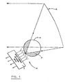
- FIG 1 illustrates a conventional multiple beam antenna configuration.
- a beam forming network (BFN) 11 supplies signals to a feed horn cluster 13, which illuminates an offset paraboloid reflector 15. If the feed horns are made relatively small for close packaging and reasonably high crossover levels 17 (as shown in Fig. 2), a significant portion of the beam misses the reflector, becoming spillover loss 21.
- a partial solution to the spillover loss problem is described by the inventor in Wokurka, A Feed Cluster Image Reduction System, Digest, IEEE AP-S Symposium, Blacksburg, Virginia, June 1987, pages 199-202.
- an "imaging" lens is used to produce an optically reduced image of a large feed horn cluster.
- the reduced image of the feed horns is then used to illuminate the collimating reflector or dielectric lens.
- a field lens is placed between the imaging lens and the objective lens to efficiently refract the energy from each feed horn onto the objective lens, thereby maintaining low spillover loss for each beam at the objective lens.
- Another system that has been suggested is to form overlapping feed horn subclusters with a more complex beam forming network.
- energy to be radiated in a beam is divided in the BFN and applied to several adjacent horns.
- This approach increases the feed aperture size, and narrows the feed radiation pattern, to more efficiently illuminate the reflector.
- Adjacent beams are produced by overlapping these clustered feed horns.
- this approach complicates the feed network greatly, particularly for millimeter wave length signals and/or systems using a large number of beams.
- This approach also adds significantly to waveguide or transmission line losses. Such increased complexity and losses are particularly pronounced at higher millimeter wave frequencies, where they are least tolerable.
- Another proposed solution to the spillover loss problem is to build several antennas, each of which produces widely spaced beams that are a portion of the total required. The beams from the separate antennas are then interlaced in space to create the full coverage complement. Clearly, this approach adds much unnecessary weight and volume to the antenna system by adding more antennas.
- the present invention is a multiple beam antenna system that includes a beam forming network that includes a plurality of feed horns in a feed horn cluster and objective.
- An imaging lens having a lateral magnification less than one for focusing a reduced image of the feed horn cluster at a predetermined point in space is placed next to the horn cluster.
- a field lens is positioned at that predetermined point in space, and an amplitude shaping lens is positioned between the field lens and the objective.
- the amplitude shaping lens redirects the rays of the image transmitted by the field lens to be denser in the central region of the objective and consequently reduces the sidelobes in the far field pattern of the transmitted beam.
- Figure 1 shows a conventional multiple beam antenna system.
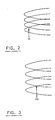
- Figure 2 shows beams having high crossover levels.
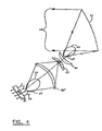
- Figure 3 shows beams having low crossover levels.
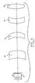
- Figure 4 illustrates one embodiment of the multiple beam antenna system of the invention.
- Figure 5 illustrates an alternative embodiment of the invention incorporating an objective lens instead of an objective reflector.
- spillover loss from individual microwave horns in a feed horn cluster used in conventional multiple beam antenna designs is reduced by the placement of three dielectric lenses between the feed cluster and the final collimating reflector or lens.
- the present invention incorporates a beam forming network 31, which may be of the type generally known and understood in the industry.
- This beam forming network transmits beams through a feed horn cluster 33.
- feed horn clusters and their attributes are also well understood in the art.
- An imaging lens 35 is placed in the path of the beams 37 from the feed horn cluster.
- This imaging lens 35 has a lateral magnification of less than unity, so that an optically-reduced image of the feed horn cluster is produced at the field lens 43.
- the imaging lens can be shaped and positioned so that a minimum portion of the beams 37 produced by the feed horn cluster bypass the lens. This provides minimum spillover loss 39 from the feed horn cluster.
- the imaging lens 35 focuses the reduced image of the feed horns at a point in space.
- the reduced feed horn image can be used to illuminate an offset reflector 41.
- the objective 41 is an offset paraboloid reflector.
- a lens may function as the objective.
- the field lens 43 is placed at the feed horn image to efficiently refract the energy from each feed horn of the feed horn cluster onto the objective reflector 41.
- a maximum of the beams 45 impact the objective reflector 41, providing minimal spillover loss 47.
- the imaging lens 35 forms overlapped and clustered feed distributions optically in space at the field lens plane, so that the image formed at the field lens is a small overlapped replica of the physically larger real cluster.
- the imaging lens may provide a 0.5 lateral magnification (or image reduction) factor of the actual feed horn cluster. Focusing the reduced image of the feed horn cluster at the field lens 43 causes the energy to appear to the objective reflector 41 as though it were coming from a more closely spaced feed horn cluster, with correspondingly closer horn phase centers.
- the radiated beams are therefore spaced more closely in space, resulting in higher beam crossovers.
- a given crossover level can be realized by properly choosing the lateral magnification of the imaging lens during the design of the system.
- a higher beam crossover level results in a higher minimum gain of the composite antenna gain coverage.
- the collimated beams 49 reflected from the reflector 41 may contain significant sidelobes in the far field pattern due to beam diffraction.
- an amplitude shaping lens 51 redirects more of the energy rays in the central part of the reflector.
- the amplitude shaping lens alters the "ray bunching" or power density distribution so that the rays of energy from the antenna horns are denser in the central region of the system.
- the amplitude shaping lens concentrates the power of the beams in the central part of the collimating reflector, giving rise to low sidelobe reflected beams 49. Increasing the power density in the central portion of the beam pattern reduces beam diffraction and the associated sidelobes in the beam pattern.
- Amplitude shaping is accomplished primarily through refraction at the first surface of the amplitude shaping lens 51.
- the second surface is contoured mainly to satisfy the phase constraint.
- the chosen shape of the lens is sensitive to the central thickness of the lens and the distance from the field lens 43 to the amplitude shaping lens 51, and the central thickness of the amplitude shaping lens.
- Some amplitude shaping can be done by the objective reflector lens 41. However, such shaping by the objective would likely be at odds with the wide-angle "scanning" requirement for the multiple beams of a multiple beam antenna system.
- Equations for the paraxial rays (those close to the axis that satisfy the small angle approximation) for each lens may be derived, depending on the lens material, its dielectric constant, and the lens thickness.
- Geometrical optics computer programs can be used to trace rays through the different lenses of the system and determine the aspheric term coefficients specifying the surface away from the central axis.
- a scalar defraction theory computer program can be used to determine the amplitude and phase distributions on each lens surface and calculate the far field radiation patterns.
- the geometrical optics program can be used to successively determine higher order coefficients of the lens surface expressions to focus, with the imaging lens, the non-paraxial rays at the focused spot images of each feed horn in the field lens plane. This helps to insure that the non-paraxial rays are not spilled over, but rather fall on the objective reflector for each feed horn to realize high aperture efficiency. Additionally, the surface coefficients of the objective reflector or objective lens can be determined to ensure a low phase error distribution (preferably 50 degrees maximum) across the aperture for each beam.
- the lenses for a system for 44 GHz wavelengths may be fabricated of a dielectric material, such as alumina having a dielectric constant of 9.72.
- the center of each lens may be approximately one inch thick.
- the amplitude shaping lens 51 in particular should have a center of sufficient thickness to ensure that enough dielectric medium is present at the outer rim of the lens for the rays to converge and perform the power transformation required.
- the distance from the edge of the feed horns to the objective reflector or the far surface of an objective lens may be approximately 32.2 inches.
- the lenses may be installed in an eight inch diameter stainless steel machined tube.
- the position of the imaging lens 35 may be fixed, while the field lens 43, amplitude shaping lens 51, and objective lens 53 or reflector 41 may have adjustable positions.
- the present invention also increases the "hardness" of the system to electromagnetic and particle beam threats by virtue of the hard lens material shielding the feed horns and the sensitive receivers connected to the antenna feed network ports.
- the lens surface could also be made reflective or diffuse at other threat frequencies, such as in the laser optical spectrum.
- the present invention allows the final objective aperture distribution to be phase corrected by adjusting higher order coefficients in the lens surface equations so as to improve beam distortion resulting from feeds progressively farther from the feed cluster access of symmetry.
- the collimator or objective is shown in Figure 4 as an offset reflector. Nevertheless, the collimator could equally be a lens 53, as shown in Figured 5. Such a lens would be more appropriate for high millimeter wave frequencies (EHF), where the apertures need not be large, and the lens weight would not be excessive.
- EHF millimeter wave frequencies
Description
- The present invention relates to multiple beam antenna (MBA) systems, such as are useful for communication satellites. Specifically, the present invention provides a microwave multiple beam antenna system that simultaneously achieves closely spaced beams (high crossover levels) and high aperture efficiency (low spillover loss) with a relatively simple beam forming network.
- Conventional MBA designs, typically for communication satellites, place the feed horn cluster of the antenna at the focal point of an offset reflector collimator, as shown in Figure 1. The feed horns are designed to be relatively small for close packaging in the cluster to give reasonably high crossover levels (i.e., closely spaced beams). A small feed horn, however, produces a broad radiation pattern for illuminating the offset reflector. This results in much of the energy not being intercepted by the reflector, and gives rise to high spillover loss. On the other hand, if the feed horns are designed for more directive beams to reduce the spillover loss, the feed horns become larger, yielding wider beam separation, and thus lower crossover levels. The result is "holes" in the pattern coverage.
- Figure 1 illustrates a conventional multiple beam antenna configuration. A beam forming network (BFN) 11 supplies signals to a
feed horn cluster 13, which illuminates anoffset paraboloid reflector 15. If the feed horns are made relatively small for close packaging and reasonably high crossover levels 17 (as shown in Fig. 2), a significant portion of the beam misses the reflector, becomingspillover loss 21. Alternative feed horns that produce more directive beams to reduce the spillover loss, produce lowbeam crossover levels 23 in the beams reflected from the offset paraboloid reflector, as shown in Figure 3. - A partial solution to the spillover loss problem is described by the inventor in Wokurka, A Feed Cluster Image Reduction System, Digest, IEEE AP-S Symposium, Blacksburg, Virginia, June 1987, pages 199-202. In the system there described, an "imaging" lens is used to produce an optically reduced image of a large feed horn cluster. The reduced image of the feed horns is then used to illuminate the collimating reflector or dielectric lens. A field lens is placed between the imaging lens and the objective lens to efficiently refract the energy from each feed horn onto the objective lens, thereby maintaining low spillover loss for each beam at the objective lens.
- Another system that has been suggested is to form overlapping feed horn subclusters with a more complex beam forming network. With this approach, energy to be radiated in a beam is divided in the BFN and applied to several adjacent horns. This approach increases the feed aperture size, and narrows the feed radiation pattern, to more efficiently illuminate the reflector. Adjacent beams are produced by overlapping these clustered feed horns. However, this approach complicates the feed network greatly, particularly for millimeter wave length signals and/or systems using a large number of beams. This approach also adds significantly to waveguide or transmission line losses. Such increased complexity and losses are particularly pronounced at higher millimeter wave frequencies, where they are least tolerable.
- Another proposed solution to the spillover loss problem is to build several antennas, each of which produces widely spaced beams that are a portion of the total required. The beams from the separate antennas are then interlaced in space to create the full coverage complement. Clearly, this approach adds much unnecessary weight and volume to the antenna system by adding more antennas.
- The present invention is a multiple beam antenna system that includes a beam forming network that includes a plurality of feed horns in a feed horn cluster and objective. An imaging lens having a lateral magnification less than one for focusing a reduced image of the feed horn cluster at a predetermined point in space is placed next to the horn cluster. A field lens is positioned at that predetermined point in space, and an amplitude shaping lens is positioned between the field lens and the objective. The amplitude shaping lens redirects the rays of the image transmitted by the field lens to be denser in the central region of the objective and consequently reduces the sidelobes in the far field pattern of the transmitted beam.
- Figure 1 shows a conventional multiple beam antenna system.
- Figure 2 shows beams having high crossover levels.
- Figure 3 shows beams having low crossover levels.
- Figure 4 illustrates one embodiment of the multiple beam antenna system of the invention.
- Figure 5 illustrates an alternative embodiment of the invention incorporating an objective lens instead of an objective reflector.
- In the present invention, spillover loss from individual microwave horns in a feed horn cluster used in conventional multiple beam antenna designs is reduced by the placement of three dielectric lenses between the feed cluster and the final collimating reflector or lens.
- The present invention incorporates a
beam forming network 31, which may be of the type generally known and understood in the industry. This beam forming network transmits beams through afeed horn cluster 33. Such feed horn clusters and their attributes are also well understood in the art. - An
imaging lens 35 is placed in the path of thebeams 37 from the feed horn cluster. Thisimaging lens 35 has a lateral magnification of less than unity, so that an optically-reduced image of the feed horn cluster is produced at thefield lens 43. The imaging lens can be shaped and positioned so that a minimum portion of thebeams 37 produced by the feed horn cluster bypass the lens. This providesminimum spillover loss 39 from the feed horn cluster. - The
imaging lens 35 focuses the reduced image of the feed horns at a point in space. The reduced feed horn image can be used to illuminate an offset reflector 41. In the embodiment illustrated in Figure 4, the objective 41 is an offset paraboloid reflector. Alternatively, a lens may function as the objective. - The
field lens 43 is placed at the feed horn image to efficiently refract the energy from each feed horn of the feed horn cluster onto the objective reflector 41. By properly refracting the beams from the optically reduced image of the feed horn cluster, a maximum of thebeams 45 impact the objective reflector 41, providingminimal spillover loss 47. - The
imaging lens 35 forms overlapped and clustered feed distributions optically in space at the field lens plane, so that the image formed at the field lens is a small overlapped replica of the physically larger real cluster. The imaging lens may provide a 0.5 lateral magnification (or image reduction) factor of the actual feed horn cluster. Focusing the reduced image of the feed horn cluster at thefield lens 43 causes the energy to appear to the objective reflector 41 as though it were coming from a more closely spaced feed horn cluster, with correspondingly closer horn phase centers. - By using larger feed horns, with their associated more directive patterns as the elements of the feed cluster, and optically reducing the size of this cluster with the imaging dielectric lens, spillover loss is reduced. The feed horn amplitude taper at the imaging lens edge can be made to be -10dB, resulting in
low spillover loss 39 at the imaging lens. - The radiated beams are therefore spaced more closely in space, resulting in higher beam crossovers. A given crossover level can be realized by properly choosing the lateral magnification of the imaging lens during the design of the system. A higher beam crossover level results in a higher minimum gain of the composite antenna gain coverage.
- With a uniform amplitude or power density distribution across the objective 41, the
collimated beams 49 reflected from the reflector 41 may contain significant sidelobes in the far field pattern due to beam diffraction. To reduce the sidelobes in the far field pattern, an amplitude shapinglens 51 redirects more of the energy rays in the central part of the reflector. Thus, the amplitude shaping lens alters the "ray bunching" or power density distribution so that the rays of energy from the antenna horns are denser in the central region of the system. The amplitude shaping lens concentrates the power of the beams in the central part of the collimating reflector, giving rise to low sidelobe reflectedbeams 49. Increasing the power density in the central portion of the beam pattern reduces beam diffraction and the associated sidelobes in the beam pattern. - Amplitude shaping is accomplished primarily through refraction at the first surface of the
amplitude shaping lens 51. The second surface is contoured mainly to satisfy the phase constraint. Ordinarily, the chosen shape of the lens is sensitive to the central thickness of the lens and the distance from thefield lens 43 to theamplitude shaping lens 51, and the central thickness of the amplitude shaping lens. Some amplitude shaping can be done by the objective reflector lens 41. However, such shaping by the objective would likely be at odds with the wide-angle "scanning" requirement for the multiple beams of a multiple beam antenna system. - Equations for the paraxial rays (those close to the axis that satisfy the small angle approximation) for each lens may be derived, depending on the lens material, its dielectric constant, and the lens thickness. Geometrical optics computer programs can be used to trace rays through the different lenses of the system and determine the aspheric term coefficients specifying the surface away from the central axis. A scalar defraction theory computer program can be used to determine the amplitude and phase distributions on each lens surface and calculate the far field radiation patterns.
- The geometrical optics program can be used to successively determine higher order coefficients of the lens surface expressions to focus, with the imaging lens, the non-paraxial rays at the focused spot images of each feed horn in the field lens plane. This helps to insure that the non-paraxial rays are not spilled over, but rather fall on the objective reflector for each feed horn to realize high aperture efficiency. Additionally, the surface coefficients of the objective reflector or objective lens can be determined to ensure a low phase error distribution (preferably 50 degrees maximum) across the aperture for each beam.
- The lenses for a system for 44 GHz wavelengths may be fabricated of a dielectric material, such as alumina having a dielectric constant of 9.72. The center of each lens may be approximately one inch thick. The
amplitude shaping lens 51 in particular should have a center of sufficient thickness to ensure that enough dielectric medium is present at the outer rim of the lens for the rays to converge and perform the power transformation required. - For such a system for 44 GHz wavelengths, the distance from the edge of the feed horns to the objective reflector or the far surface of an objective lens may be approximately 32.2 inches. The lenses may be installed in an eight inch diameter stainless steel machined tube. The position of the
imaging lens 35 may be fixed, while thefield lens 43,amplitude shaping lens 51, andobjective lens 53 or reflector 41 may have adjustable positions. - The present invention also increases the "hardness" of the system to electromagnetic and particle beam threats by virtue of the hard lens material shielding the feed horns and the sensitive receivers connected to the antenna feed network ports. The lens surface could also be made reflective or diffuse at other threat frequencies, such as in the laser optical spectrum.
- The present invention allows the final objective aperture distribution to be phase corrected by adjusting higher order coefficients in the lens surface equations so as to improve beam distortion resulting from feeds progressively farther from the feed cluster access of symmetry.
- The collimator or objective is shown in Figure 4 as an offset reflector. Nevertheless, the collimator could equally be a
lens 53, as shown in Figured 5. Such a lens would be more appropriate for high millimeter wave frequencies (EHF), where the apertures need not be large, and the lens weight would not be excessive.
Claims (3)
- A multiple beam antenna system comprising along a system axis:a beam forming network (31) including a plurality of feed horns in a feed horn cluster (33),an imaging lens (35) for focusing at a predetermined point in space an image of said feed horn cluster, the respective distances between said imaging lens, said predetermined point and said feed horn cluster being chosen such that said image of the feed horn cluster is smaller than said feed horn cluster,a field lens (43) positioned at said predetermined point in space,and an objective (41, 53) to project in the far field the energy coming from said field lens in emission characterised in thatit also comprises an amplitude shaping lens (51) positioned between said field lens (43) and said objective (41,53) wherein said amplitude shaping lens (51) alters the amplitude distribution of the beams to converge the power density toward the lens axis.
- The multiple beam antenna system of Claim 1, wherein said objective comprises an offset paraboloid reflector.
- The multiple beam antenna system of Claim 1, wherein said objective comprises an objective lens.
Applications Claiming Priority (2)
| Application Number | Priority Date | Filing Date | Title |
|---|---|---|---|
| US607389 | 1990-10-31 | ||
| US07/607,389 US5206658A (en) | 1990-10-31 | 1990-10-31 | Multiple beam antenna system |
Publications (2)
| Publication Number | Publication Date |
|---|---|
| EP0483686A1 EP0483686A1 (en) | 1992-05-06 |
| EP0483686B1 true EP0483686B1 (en) | 1996-04-10 |
Family
ID=24432061
Family Applications (1)
| Application Number | Title | Priority Date | Filing Date |
|---|---|---|---|
| EP91118243A Expired - Lifetime EP0483686B1 (en) | 1990-10-31 | 1991-10-25 | Multiple beam antenna system |
Country Status (5)
| Country | Link |
|---|---|
| US (1) | US5206658A (en) |
| EP (1) | EP0483686B1 (en) |
| JP (1) | JP2632457B2 (en) |
| CA (1) | CA2054560C (en) |
| DE (1) | DE69118651T2 (en) |
Cited By (6)
| Publication number | Priority date | Publication date | Assignee | Title |
|---|---|---|---|---|
| EP1236245A1 (en) * | 1999-11-18 | 2002-09-04 | Automotive Systems Laboratory Inc. | Multi-beam antenna |
| US7042420B2 (en) | 1999-11-18 | 2006-05-09 | Automotive Systems Laboratory, Inc. | Multi-beam antenna |
| US7358913B2 (en) | 1999-11-18 | 2008-04-15 | Automotive Systems Laboratory, Inc. | Multi-beam antenna |
| US7411542B2 (en) | 2005-02-10 | 2008-08-12 | Automotive Systems Laboratory, Inc. | Automotive radar system with guard beam |
| US7605768B2 (en) | 1999-11-18 | 2009-10-20 | TK Holdings Inc., Electronics | Multi-beam antenna |
| US7898480B2 (en) | 2005-05-05 | 2011-03-01 | Automotive Systems Labortaory, Inc. | Antenna |
Families Citing this family (16)
| Publication number | Priority date | Publication date | Assignee | Title |
|---|---|---|---|---|
| GB2517661B (en) * | 1995-10-24 | 2016-03-30 | Thomson Csf | An anti-jamming antenna |
| IT1284301B1 (en) * | 1996-03-13 | 1998-05-18 | Space Engineering Spa | SINGLE OR DOUBLE REFLECTOR ANTENNA, SHAPED BEAMS, LINEAR POLARIZATION. |
| US6678520B1 (en) * | 1999-01-07 | 2004-01-13 | Hughes Electronics Corporation | Method and apparatus for providing wideband services using medium and low earth orbit satellites |
| US6445351B1 (en) | 2000-01-28 | 2002-09-03 | The Boeing Company | Combined optical sensor and communication antenna system |
| US6441793B1 (en) * | 2000-03-16 | 2002-08-27 | Austin Information Systems, Inc. | Method and apparatus for wireless communications and sensing utilizing a non-collimating lens |
| US6396453B2 (en) * | 2000-04-20 | 2002-05-28 | Ems Technologies Canada, Ltd. | High performance multimode horn |
| US7200360B1 (en) | 2000-06-15 | 2007-04-03 | The Directv Group, Inc. | Communication system as a secondary platform with frequency reuse |
| JP4456998B2 (en) * | 2004-12-28 | 2010-04-28 | 日立オートモティブシステムズ株式会社 | Speed sensor and ground vehicle speed sensor using the same |
| WO2007136289A1 (en) * | 2006-05-23 | 2007-11-29 | Intel Corporation | Millimeter-wave chip-lens array antenna systems for wireless networks |
| CN101427486B (en) * | 2006-05-23 | 2013-06-19 | 英特尔公司 | Millimeter-wave communication system with directional antenna and one or more millimeter-wave reflectors |
| US8320942B2 (en) * | 2006-06-13 | 2012-11-27 | Intel Corporation | Wireless device with directional antennas for use in millimeter-wave peer-to-peer networks and methods for adaptive beam steering |
| DE102007036262A1 (en) * | 2007-08-02 | 2009-02-05 | Robert Bosch Gmbh | Radar sensor for motor vehicles |
| DE102008001467A1 (en) * | 2008-04-30 | 2009-11-05 | Robert Bosch Gmbh | Multibeam radar sensor |
| ES2561661T3 (en) * | 2009-10-22 | 2016-02-29 | Lockheed Martin Corporation | Metamaterial lens feed for multi-beam antennas |
| DE102014106060A1 (en) * | 2014-04-30 | 2015-11-19 | Karlsruher Institut für Technologie | antenna array |
| EP3691026B1 (en) * | 2019-02-04 | 2021-05-19 | VEGA Grieshaber KG | Antenna assembly |
Family Cites Families (13)
| Publication number | Priority date | Publication date | Assignee | Title |
|---|---|---|---|---|
| US3430244A (en) * | 1964-11-25 | 1969-02-25 | Radiation Inc | Reflector antennas |
| FR1462334A (en) * | 1965-10-15 | 1966-04-15 | Thomson Houston Comp Francaise | Multibeam antenna system performing spatial spectro-analysis |
| US3396397A (en) * | 1965-10-20 | 1968-08-06 | Air Force Usa | Dielectric zoom lens for microwave beam scanning |
| US3911440A (en) * | 1971-11-08 | 1975-10-07 | Mitsubishi Electric Corp | Antenna feed system |
| JPS5556704A (en) * | 1978-10-23 | 1980-04-25 | Nec Corp | Shaping beam antenna |
| US4270129A (en) * | 1979-01-30 | 1981-05-26 | Sperry Corporation | Apparatus and method for realizing preselected free space antenna patterns |
| US4254421A (en) * | 1979-12-05 | 1981-03-03 | Communications Satellite Corporation | Integrated confocal electromagnetic wave lens and feed antenna system |
| US4435714A (en) * | 1980-12-29 | 1984-03-06 | Ford Aerospace & Communications Corp. | Grating lobe eliminator |
| US4503434A (en) * | 1983-05-02 | 1985-03-05 | Ford Aerospace & Communications Corporation | Lossless arbitrary output dual mode network |
| JPS6074802A (en) * | 1983-09-30 | 1985-04-27 | Nec Corp | Antenna |
| EP0164466B1 (en) * | 1984-06-14 | 1991-06-05 | Trw Inc. | High-efficiency multibeam antenna |
| DE3738705A1 (en) * | 1987-11-14 | 1989-05-24 | Licentia Gmbh | Arrangement for varying the lobe width of a microwave antenna |
| EP0446610A1 (en) * | 1990-03-07 | 1991-09-18 | Hughes Aircraft Company | Magnified phased array with a digital beamforming network |
-
1990
- 1990-10-31 US US07/607,389 patent/US5206658A/en not_active Expired - Lifetime
-
1991
- 1991-10-25 DE DE69118651T patent/DE69118651T2/en not_active Expired - Fee Related
- 1991-10-25 EP EP91118243A patent/EP0483686B1/en not_active Expired - Lifetime
- 1991-10-30 CA CA002054560A patent/CA2054560C/en not_active Expired - Fee Related
- 1991-10-30 JP JP3284748A patent/JP2632457B2/en not_active Expired - Lifetime
Cited By (9)
| Publication number | Priority date | Publication date | Assignee | Title |
|---|---|---|---|---|
| EP1236245A1 (en) * | 1999-11-18 | 2002-09-04 | Automotive Systems Laboratory Inc. | Multi-beam antenna |
| EP1236245A4 (en) * | 1999-11-18 | 2004-08-18 | Automotive Systems Lab | Multi-beam antenna |
| US7042420B2 (en) | 1999-11-18 | 2006-05-09 | Automotive Systems Laboratory, Inc. | Multi-beam antenna |
| US7358913B2 (en) | 1999-11-18 | 2008-04-15 | Automotive Systems Laboratory, Inc. | Multi-beam antenna |
| US7605768B2 (en) | 1999-11-18 | 2009-10-20 | TK Holdings Inc., Electronics | Multi-beam antenna |
| US7800549B2 (en) | 1999-11-18 | 2010-09-21 | TK Holdings, Inc. Electronics | Multi-beam antenna |
| US7994996B2 (en) | 1999-11-18 | 2011-08-09 | TK Holding Inc., Electronics | Multi-beam antenna |
| US7411542B2 (en) | 2005-02-10 | 2008-08-12 | Automotive Systems Laboratory, Inc. | Automotive radar system with guard beam |
| US7898480B2 (en) | 2005-05-05 | 2011-03-01 | Automotive Systems Labortaory, Inc. | Antenna |
Also Published As
| Publication number | Publication date |
|---|---|
| JPH04286206A (en) | 1992-10-12 |
| DE69118651D1 (en) | 1996-05-15 |
| US5206658A (en) | 1993-04-27 |
| JP2632457B2 (en) | 1997-07-23 |
| CA2054560A1 (en) | 1992-05-01 |
| EP0483686A1 (en) | 1992-05-06 |
| DE69118651T2 (en) | 1996-11-28 |
| CA2054560C (en) | 1998-12-01 |
Similar Documents
| Publication | Publication Date | Title |
|---|---|---|
| EP0483686B1 (en) | Multiple beam antenna system | |
| US4618867A (en) | Scanning beam antenna with linear array feed | |
| US4220957A (en) | Dual frequency horn antenna system | |
| CA1126398A (en) | Scanable antenna arrangements capable of producing a large image of a small array with minimal aberrations | |
| US4516130A (en) | Antenna arrangements using focal plane filtering for reducing sidelobes | |
| US4381509A (en) | Cylindrical microwave lens antenna for wideband scanning applications | |
| EP0086351B1 (en) | Geodesic dome/lens antenna | |
| Rotman | Wide-angle scanning with microwave double-layer pillboxes | |
| US4254421A (en) | Integrated confocal electromagnetic wave lens and feed antenna system | |
| US4145695A (en) | Launcher reflectors for correcting for astigmatism in off-axis fed reflector antennas | |
| US4825216A (en) | High efficiency optical limited scan antenna | |
| US4855751A (en) | High-efficiency multibeam antenna | |
| US4250508A (en) | Scanning beam antenna arrangement | |
| US3235870A (en) | Double-reflector antenna with polarization-changing subreflector | |
| EP2311144B1 (en) | Apparatus for an antenna system | |
| US4439773A (en) | Compact scanning beam antenna feed arrangement | |
| US4194209A (en) | Broadband waveguide lens antenna and method of fabrication | |
| JPH0417482B2 (en) | ||
| Fitzgerald | Limited electronic scanning with an offset-feed near-field Gregorian system | |
| US4786910A (en) | Single reflector multibeam antenna arrangement with a wide field of view | |
| CA1076696A (en) | Aerial system | |
| EP1207584B1 (en) | Integrated dual beam reflector antenna | |
| GB2262387A (en) | Multibeam antenna | |
| US4689632A (en) | Reflector antenna system having reduced blockage effects | |
| Ajioka et al. | Beam-forming feeds |
Legal Events
| Date | Code | Title | Description |
|---|---|---|---|
| PUAI | Public reference made under article 153(3) epc to a published international application that has entered the european phase |
Free format text: ORIGINAL CODE: 0009012 |
|
| AK | Designated contracting states |
Kind code of ref document: A1 Designated state(s): DE GB IT |
|
| 17P | Request for examination filed |
Effective date: 19921104 |
|
| 17Q | First examination report despatched |
Effective date: 19940919 |
|
| GRAA | (expected) grant |
Free format text: ORIGINAL CODE: 0009210 |
|
| GRAH | Despatch of communication of intention to grant a patent |
Free format text: ORIGINAL CODE: EPIDOS IGRA |
|
| AK | Designated contracting states |
Kind code of ref document: B1 Designated state(s): DE GB IT |
|
| ITF | It: translation for a ep patent filed |
Owner name: BARZANO' E ZANARDO ROMA S.P.A. |
|
| REF | Corresponds to: |
Ref document number: 69118651 Country of ref document: DE Date of ref document: 19960515 |
|
| PLBE | No opposition filed within time limit |
Free format text: ORIGINAL CODE: 0009261 |
|
| STAA | Information on the status of an ep patent application or granted ep patent |
Free format text: STATUS: NO OPPOSITION FILED WITHIN TIME LIMIT |
|
| 26N | No opposition filed | ||
| REG | Reference to a national code |
Ref country code: GB Ref legal event code: IF02 |
|
| PGFP | Annual fee paid to national office [announced via postgrant information from national office to epo] |
Ref country code: DE Payment date: 20081201 Year of fee payment: 18 |
|
| PGFP | Annual fee paid to national office [announced via postgrant information from national office to epo] |
Ref country code: IT Payment date: 20081030 Year of fee payment: 18 |
|
| PGFP | Annual fee paid to national office [announced via postgrant information from national office to epo] |
Ref country code: GB Payment date: 20081029 Year of fee payment: 18 |
|
| PG25 | Lapsed in a contracting state [announced via postgrant information from national office to epo] |
Ref country code: DE Free format text: LAPSE BECAUSE OF NON-PAYMENT OF DUE FEES Effective date: 20100501 |
|
| PG25 | Lapsed in a contracting state [announced via postgrant information from national office to epo] |
Ref country code: GB Free format text: LAPSE BECAUSE OF NON-PAYMENT OF DUE FEES Effective date: 20091025 |
|
| PG25 | Lapsed in a contracting state [announced via postgrant information from national office to epo] |
Ref country code: IT Free format text: LAPSE BECAUSE OF NON-PAYMENT OF DUE FEES Effective date: 20091025 |