EP0484995B1 - Method of controlling the speed of a vehicle - Google Patents
Method of controlling the speed of a vehicle Download PDFInfo
- Publication number
- EP0484995B1 EP0484995B1 EP91202687A EP91202687A EP0484995B1 EP 0484995 B1 EP0484995 B1 EP 0484995B1 EP 91202687 A EP91202687 A EP 91202687A EP 91202687 A EP91202687 A EP 91202687A EP 0484995 B1 EP0484995 B1 EP 0484995B1
- Authority
- EP
- European Patent Office
- Prior art keywords
- speed
- vehicle
- driver
- deceleration
- controlled vehicle
- Prior art date
- Legal status (The legal status is an assumption and is not a legal conclusion. Google has not performed a legal analysis and makes no representation as to the accuracy of the status listed.)
- Expired - Lifetime
Links
Images


Classifications
-
- B—PERFORMING OPERATIONS; TRANSPORTING
- B60—VEHICLES IN GENERAL
- B60T—VEHICLE BRAKE CONTROL SYSTEMS OR PARTS THEREOF; BRAKE CONTROL SYSTEMS OR PARTS THEREOF, IN GENERAL; ARRANGEMENT OF BRAKING ELEMENTS ON VEHICLES IN GENERAL; PORTABLE DEVICES FOR PREVENTING UNWANTED MOVEMENT OF VEHICLES; VEHICLE MODIFICATIONS TO FACILITATE COOLING OF BRAKES
- B60T7/00—Brake-action initiating means
- B60T7/12—Brake-action initiating means for automatic initiation; for initiation not subject to will of driver or passenger
- B60T7/22—Brake-action initiating means for automatic initiation; for initiation not subject to will of driver or passenger initiated by contact of vehicle, e.g. bumper, with an external object, e.g. another vehicle, or by means of contactless obstacle detectors mounted on the vehicle
-
- B—PERFORMING OPERATIONS; TRANSPORTING
- B60—VEHICLES IN GENERAL
- B60K—ARRANGEMENT OR MOUNTING OF PROPULSION UNITS OR OF TRANSMISSIONS IN VEHICLES; ARRANGEMENT OR MOUNTING OF PLURAL DIVERSE PRIME-MOVERS IN VEHICLES; AUXILIARY DRIVES FOR VEHICLES; INSTRUMENTATION OR DASHBOARDS FOR VEHICLES; ARRANGEMENTS IN CONNECTION WITH COOLING, AIR INTAKE, GAS EXHAUST OR FUEL SUPPLY OF PROPULSION UNITS IN VEHICLES
- B60K31/00—Vehicle fittings, acting on a single sub-unit only, for automatically controlling vehicle speed, i.e. preventing speed from exceeding an arbitrarily established velocity or maintaining speed at a particular velocity, as selected by the vehicle operator
- B60K31/0008—Vehicle fittings, acting on a single sub-unit only, for automatically controlling vehicle speed, i.e. preventing speed from exceeding an arbitrarily established velocity or maintaining speed at a particular velocity, as selected by the vehicle operator including means for detecting potential obstacles in vehicle path
-
- B—PERFORMING OPERATIONS; TRANSPORTING
- B60—VEHICLES IN GENERAL
- B60T—VEHICLE BRAKE CONTROL SYSTEMS OR PARTS THEREOF; BRAKE CONTROL SYSTEMS OR PARTS THEREOF, IN GENERAL; ARRANGEMENT OF BRAKING ELEMENTS ON VEHICLES IN GENERAL; PORTABLE DEVICES FOR PREVENTING UNWANTED MOVEMENT OF VEHICLES; VEHICLE MODIFICATIONS TO FACILITATE COOLING OF BRAKES
- B60T2220/00—Monitoring, detecting driver behaviour; Signalling thereof; Counteracting thereof
- B60T2220/02—Driver type; Driving style; Driver adaptive features
-
- B—PERFORMING OPERATIONS; TRANSPORTING
- B60—VEHICLES IN GENERAL
- B60W—CONJOINT CONTROL OF VEHICLE SUB-UNITS OF DIFFERENT TYPE OR DIFFERENT FUNCTION; CONTROL SYSTEMS SPECIALLY ADAPTED FOR HYBRID VEHICLES; ROAD VEHICLE DRIVE CONTROL SYSTEMS FOR PURPOSES NOT RELATED TO THE CONTROL OF A PARTICULAR SUB-UNIT
- B60W2540/00—Input parameters relating to occupants
- B60W2540/30—Driving style
-
- B—PERFORMING OPERATIONS; TRANSPORTING
- B60—VEHICLES IN GENERAL
- B60W—CONJOINT CONTROL OF VEHICLE SUB-UNITS OF DIFFERENT TYPE OR DIFFERENT FUNCTION; CONTROL SYSTEMS SPECIALLY ADAPTED FOR HYBRID VEHICLES; ROAD VEHICLE DRIVE CONTROL SYSTEMS FOR PURPOSES NOT RELATED TO THE CONTROL OF A PARTICULAR SUB-UNIT
- B60W2554/00—Input parameters relating to objects
- B60W2554/80—Spatial relation or speed relative to objects
- B60W2554/801—Lateral distance
-
- B—PERFORMING OPERATIONS; TRANSPORTING
- B60—VEHICLES IN GENERAL
- B60W—CONJOINT CONTROL OF VEHICLE SUB-UNITS OF DIFFERENT TYPE OR DIFFERENT FUNCTION; CONTROL SYSTEMS SPECIALLY ADAPTED FOR HYBRID VEHICLES; ROAD VEHICLE DRIVE CONTROL SYSTEMS FOR PURPOSES NOT RELATED TO THE CONTROL OF A PARTICULAR SUB-UNIT
- B60W2720/00—Output or target parameters relating to overall vehicle dynamics
- B60W2720/10—Longitudinal speed
- B60W2720/106—Longitudinal acceleration
-
- B—PERFORMING OPERATIONS; TRANSPORTING
- B60—VEHICLES IN GENERAL
- B60W—CONJOINT CONTROL OF VEHICLE SUB-UNITS OF DIFFERENT TYPE OR DIFFERENT FUNCTION; CONTROL SYSTEMS SPECIALLY ADAPTED FOR HYBRID VEHICLES; ROAD VEHICLE DRIVE CONTROL SYSTEMS FOR PURPOSES NOT RELATED TO THE CONTROL OF A PARTICULAR SUB-UNIT
- B60W2754/00—Output or target parameters relating to objects
- B60W2754/10—Spatial relation or speed relative to objects
- B60W2754/30—Longitudinal distance
-
- B—PERFORMING OPERATIONS; TRANSPORTING
- B60—VEHICLES IN GENERAL
- B60W—CONJOINT CONTROL OF VEHICLE SUB-UNITS OF DIFFERENT TYPE OR DIFFERENT FUNCTION; CONTROL SYSTEMS SPECIALLY ADAPTED FOR HYBRID VEHICLES; ROAD VEHICLE DRIVE CONTROL SYSTEMS FOR PURPOSES NOT RELATED TO THE CONTROL OF A PARTICULAR SUB-UNIT
- B60W40/00—Estimation or calculation of non-directly measurable driving parameters for road vehicle drive control systems not related to the control of a particular sub unit, e.g. by using mathematical models
- B60W40/08—Estimation or calculation of non-directly measurable driving parameters for road vehicle drive control systems not related to the control of a particular sub unit, e.g. by using mathematical models related to drivers or passengers
- B60W40/09—Driving style or behaviour
-
- G—PHYSICS
- G01—MEASURING; TESTING
- G01S—RADIO DIRECTION-FINDING; RADIO NAVIGATION; DETERMINING DISTANCE OR VELOCITY BY USE OF RADIO WAVES; LOCATING OR PRESENCE-DETECTING BY USE OF THE REFLECTION OR RERADIATION OF RADIO WAVES; ANALOGOUS ARRANGEMENTS USING OTHER WAVES
- G01S13/00—Systems using the reflection or reradiation of radio waves, e.g. radar systems; Analogous systems using reflection or reradiation of waves whose nature or wavelength is irrelevant or unspecified
- G01S13/88—Radar or analogous systems specially adapted for specific applications
- G01S13/93—Radar or analogous systems specially adapted for specific applications for anti-collision purposes
- G01S13/931—Radar or analogous systems specially adapted for specific applications for anti-collision purposes of land vehicles
- G01S2013/9321—Velocity regulation, e.g. cruise control
Definitions
- Vehicle cruise control systems are popular equipment on conventional vehicles. Recently, adaptive cruise control systems have been proposed, where, in addition to conventional factors, external factors are considered in the control of vehicle speed.
- Known automatic systems attempt to maintain a desired speed, set by the driver, but are capable of detecting obstacles in front of the vehicle, and are capable of adapting the vehicle speed in response thereto.
- a driver "spacing input” 24 is provided, which may be a dial located in proximity to the vehicle instrument panel (not shown), enables the driver may influence the speed control system according to his desired driving style.
- the spacing input set by the driver in this manner affects the desired inter-vehicle spacing RNG D , the minimum allowable spacing D MIN , the maximum tolerable vehicle deceleration value, and the vehicle braking reaction time T RB . The manner in which these parameters are affected is be described below.
- step 52 the general parameters used in this embodiment are read and stored in RAM.
- these parameters are determined using the conventional obstacle detection system 20 of Figure 2, which periodically scans a predetermined area ahead of the controlled vehicle for obstacles such as a preceding vehicle 12. From the reflection of the signal used in scanning, the detection system calculates, even in the absence of an obstacle, the range or distance RNG A to the assumed obstacle, the rate that the range is changing with respect to a predetermined period, and the velocity V T of the assumed obstacle. Additionally, at this step the velocity V o of the controlled vehicle 10 is read using the vehicle speed sensor 22 of Figure 2, and is stored in RAM.
- MIN D is a function that limits the deceleration of the vehicle to a predetermined minimum, such as the level road coast rate, to reduce driver perception of the final stages of deceleration, as will be described. This function is used in mode 2 control when deceleration is carefully controlled, and therefore is deactivated here.
- step 148 After communicating the change in brake pressure to the brake control module 30, the sub-routine proceeds to step 148, where it returns to step 102 of the routine illustrated in Figure 4.
Description
- This invention relates to a method of controlling the speed of a vehicle.
- Vehicle cruise control systems are popular equipment on conventional vehicles. Recently, adaptive cruise control systems have been proposed, where, in addition to conventional factors, external factors are considered in the control of vehicle speed. Known automatic systems attempt to maintain a desired speed, set by the driver, but are capable of detecting obstacles in front of the vehicle, and are capable of adapting the vehicle speed in response thereto.
- Commonly, these adaptive systems adjust vehicle speed in response to detected obstacles in such a manner as to cause speed perturbations perceptible to the driver of the vehicle. These perturbations may affect driver comfort or driver confidence in the adaptive speed control system, with the result that they can affect the commercial value of such systems.
- Conventional systems also prescribe control based on presumed driver capabilities, such that all drivers alike must succumb to the deceleration rate, brake reaction time and minimum following distance allowed by the system, if any. These parameter settings may not be consistent with the driver's preferred driving style, undermining the desirability of using the adaptive speed control system. A method in accordance with the preamble of
Claim 1 is disclosed in EP-A-0145989. - The present invention seeks to provide an improved method of controlling the speed of a vehicle.
- A method of controlling the speed of a vehicle in accordance with the present invention is characterised over EP-A-0145989 by the features specified in the characterising portion of
Claim 1. - The invention can overcome the shortcomings of the prior art systems by carefully controlling the vehicle speed at all times when obstacles are present, including during control transitions, with a primary objective of minimizing speed perturbations that may be unpleasant to the driver. Additionally, the method can compensate for driver response time by allowing the driver to introduce a preferred reaction time which affects not only minimum desired inter-vehicle spacing, but also braking response time and a maximum allowable deceleration value.
- In general, this method can determine a desired following distance or spacing between the controlled vehicle and vehicles ahead of the controlled vehicle. This distance may be based on a driver selected "spacing input". If a vehicle detected ahead of the subject vehicle is outside the desired distance, the subject vehicle speed can be controlled with respect to the preceding vehicle in a first mode, in a manner common in the art.
- However, if the actual spacing is less than the desired spacing, the method can operate in a second control mode and calculate a deceleration rate by which to decelerate the vehicle, such that as the distance to the preceding vehicle approaches a driver-influenced minimum distance, the controlled vehicle speed will approach the speed of the preceding vehicle. Upon reaching a predetermined minimum deceleration value, the vehicle may be further carefully decelerated at that predetermined value, which may be the level road coasting rate for that vehicle, allowing the inter-vehicle spacing to increase until that spacing reaches the desired spacing, at which time a conventional speed control mode can come into effect to maintain the vehicle at or near the desired spacing.
- Unlike the prior systems, this invention can provide smooth changes between control modes, placing importance on minimizing control perturbations. The rate of deceleration can also be continually controlled for accuracy and repeatability; and can be set to provide a beneficial trade-off between smoothness and precise operation. Additionally, the rate of deceleration, the braking harshness and response and the minimum possible spacing can be tailored to the individual driver's driving style.
- According to another aspect of the present invention, there is provided a method of controlling the speed of a vehicle as specified in claim 6.
- An embodiment of the present invention is described below, by way of illustration only, with reference to the accompanying drawings, in which:-
- Figure 1 is a diagram illustrating the relationship between range and speed for an embodiment using two control modes;
- Figure 2 is a diagram of an embodiment of electronic controller for implementing the control modes of Figure 1;
- Figures 3 to 6 and 8 are computer flow charts illustrating the steps carried out by the electronic controller of Figure 2; and
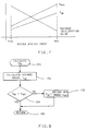
- Figure 7 is a graph illustrating the basic relationship between a driver's desired spacing and minimum following distance, braking reaction time, and maximum allowable deceleration value.
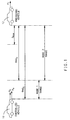
- Referring to Figure 1, when the adaptive speed control system of an automotive vehicle 10 (hereinafter referred to as the controlled vehicle), which is travelling at a speed Vo and which has an acceleration Ao, detects a preceding
vehicle 12 travelling at a speed VT it ascertains the speed of the precedingvehicle 12, the distance between the two vehicles (range), and the rate of change of this distance (range rate). - Upon sensing the preceding
vehicle 12, the control system calculates a desired range RNGD at which the twovehicles mode 1, shown in Figure 1, and amode 1 speed control is activated. Alternatively, if RNGA is less than RNGD, the range is classified as being withinmode 2, also shown in Figure 1, and amode 2 speed control is activated. In order to minimize the possibility of the control system oscillating betweenmodes mode 2 tomode 1, RNGA must exceed RNGD by an amount determined by the extent of the hysteresis band. - In general, when the control system is operating in
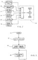
mode 1, it controls the speed of the controlledvehicle 10 in a conventional manner, such that thevehicle 10 approaches the desired range RNGD, but does not come within it. Inmode 2 the control system establishes, on the basis of the driver's entered desired spacing, an absolute minimum distance, shown in Figure 1 as DMIN, and controls the deceleration AD of thevehicle 10 in such a manner that as range RNGA approaches DMIN, the speed Vo of the controlledvehicle 10 approaches the speed VT of the precedingvehicle 12. When AD, which decreases in magnitude as Vo approaches VT, reaches a predetermined minimum deceleration value, it is held at that value until the actual range RNGA between the twovehicles mode 1 then operates to control the speed of the controlledvehicle 10. - Referring to Figure 2, a conventional
obstacle detection unit 20, such as a common radar system, is mounted in a forward position in the controlledvehicle 10, such that it is capable of detecting obstacles ahead of thevehicle 10, in particular precedingvehicles 12 in the path of the controlledvehicle 10. Information from thedetection system 20 is transmitted to anadaptive speed controller 18, such that, if a precedingvehicle 12 is present, thecontroller 18 is provided with the travelling speed of that vehicle VT, the range or inter-vehicle spacing RNGA, and the rate of change of that spacing. - A conventional
vehicle speed sensor 22 transmits the travelling speed Vo of the controlledvehicle 10 to thecontroller 18. The controller may use this information to calculate the acceleration Ao of the controlledvehicle 10. - A driver "spacing input" 24 is provided, which may be a dial located in proximity to the vehicle instrument panel (not shown), enables the driver may influence the speed control system according to his desired driving style. The spacing input set by the driver in this manner affects the desired inter-vehicle spacing RNGD, the minimum allowable spacing DMIN, the maximum tolerable vehicle deceleration value, and the vehicle braking reaction time TRB. The manner in which these parameters are affected is be described below.
- In general, the
adaptive speed controller 18, when the vehicle conventionalcruise control module 26 is active, attempts to classify the relationship between the controlledvehicle 10 and a sensed preceding vehicle 12 (if present) into one of two modes,mode 1 andmode 2, corresponding to two speed control strategies. Upon such classification, the appropriate control strategy is executed, and an appropriate control command is issued such as a braking command to abrake control module 30, or as a revised cruise control set speed to thecruise control module 26. - In this embodiment, the
adaptive speed controller 18 may include any conventional microprocessing unit, such as a Motorola MC68HC11 single chip micro-controller. - The type of control command issued corresponds to the level of control intervention necessary under the detected circumstances. For example, in
mode 1, only subtle control of vehicle speed is necessary such that the desired vehicle speed may be attained by simply adjusting the cruise control set speed. Thecruise control module 26 may then control throttle position in a conventional manner on the basis of the adjusted desired speed. However, inmode 2, greater control is required to control vehicle speed appropriately, such that cutting of power to the vehicle engine or braking may be required. - An
alarm indicator 28 is provided to warn the driver when conditions require his intervention, such as a need for a deceleration that exceeds a predetermined maximum deceleration possible with the system as set. However, in other embodiments, the driver may also be notified of less severe situations, such as when the controlledvehicle 10 moves closer to the precedingvehicle 12 than the desired following distance or simply when the system detects a precedingvehicle 12. - The
cruise control module 26 is connected to thespeed controller 18 and communicates to the controller 18 a driver set speed VSET which is the driver's requested cruising speed, and a cruise enable signal, indicating whether cruise control is currently active. This request is within the driver's control, in that the driver may request cruise control, cancel that request, or temporarily suspend that request in a conventional manner, and thereby deactivate cruise, so as to disable the control by thecontroller 18. For example, the driver may enable cruise control by setting a switch located in proximity to the instrument panel. He may cancel the cruise control by resetting that switch, or by interrupting power to thecruise control system 26. Finally, he may temporarily suspend cruise control by engaging the vehicle brakes, or by requesting a change in the set speed. In this embodiment, when conventional cruise control has been disabled, adaptive speed control also becomes inactive. - The adaptive
speed control module 18, if active, transmits a set speed to thecruise control module 26. This speed will be the same as the driver set speed if there is no precedingvehicle 12 present or if the desired speed determined by the adaptivespeed control system 18 exceeds the driver set speed. Otherwise, the transmitted set speed will be some value less than the driver set speed. - The adaptive
speed control module 26 also sets a "brakes enabled" flag when braking is required. Thecruise control module 26 has access to this flag, and disables cruise control when the flag shows the brakes to be engaged. When cruise control is disabled in this manner, the throttle blade is automatically closed or is allowed to close such that the effect of the brakes, which will be trying to decelerate the vehicle, is not opposed by engine power, i.e. via an open throttle. When the system determines that the brakes are no longer needed, the brakes enabled flag is deactivated, such that normal cruise control may resume. - Referring to Figure 3, when power is applied to the system, such as when the vehicle ignition is turned to its "on" position, the routine starts at
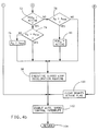
step 40, and proceeds to step 42 where the system is initialized. At this step data constants are loaded from ROM locations to RAM locations, and counters, pointers and flags are initialized. The routine then proceeds to step 44, where interrupts used in the operation of the routine are enabled. - Next, the routine proceeds to a background loop at
step 46, which is continuously repeated while the system is operating. In this loop, system maintenance and diagnostic routines may be executed. This loop is interrupted by the main control routine illustrated in Figure 4. In this embodiment, an interrupt is programmed to occur every 125 milliseconds. - Referring to Figure 4, the
processor 18, on servicing the speed control interrupt proceeds to step 48. In general, when the driver has requested cruise control, this interrupt routine examines vehicle operating conditions and the vehicle's relationship to any precedingvehicle 12, if present, and based on that examination either determines a new vehicle set speed, which is communicated to thecruise control module 26, or determines that braking is necessary, at which time cruise control is temporarily disabled, and a brake pressure command is transmitted to the conventionalbrake control module 30. Thebrake control module 30 in this embodiment is a common vehicle traction controller. If no precedingvehicle 12 is detected, the routine in this embodiment simply passes the driver set speed through to thecruise control module 26, for use in a conventional cruise control algorithm. - Specifically, the routine proceeds from
step 48 to step 50, where a check is made to determine whether the driver has requested cruise control. If no such request has been made, or if, in a conventional manner, the cruise has been disabled for example by the driver applying the brakes, or by the driver turning off cruise control via a conventional cruise control set switch, this routine is left throughstep 102, which simply resets the interrupt service routine to cause it to occur again at the predetermined time (125 milliseconds). After resetting the interrupt atstep 102, the routine proceeds to step 104, where control is returned to the background loop of Figure 3. - If, at
step 50, it is determined that the driver has requested cruise control, the routine proceeds to step 52, where the general parameters used in this embodiment are read and stored in RAM. In this embodiment, these parameters are determined using the conventionalobstacle detection system 20 of Figure 2, which periodically scans a predetermined area ahead of the controlled vehicle for obstacles such as a precedingvehicle 12. From the reflection of the signal used in scanning, the detection system calculates, even in the absence of an obstacle, the range or distance RNGA to the assumed obstacle, the rate that the range is changing with respect to a predetermined period, and the velocity VT of the assumed obstacle. Additionally, at this step the velocity Vo of the controlledvehicle 10 is read using thevehicle speed sensor 22 of Figure 2, and is stored in RAM. - The routine then proceeds to step 54, to check whether in fact there is an obstacle ahead of the
vehicle 10, such as a precedingvehicle 12. This check may be made by examining the range value received atstep 52, such that if this value is excessively large, it is assumed that no preceding obstacle is currently present. A detected obstacle may be assumed to be a precedingvehicle 12. The characteristics of the precedingvehicle 12 then becomes a factor with which the speed control of the controlledvehicle 10 may be changed. Although this embodiment assumes a preceding obstacle may be avehicle 12, it will, of course, apply to any detected obstacle in the path of the controlledvehicle 10. - If no preceding obstacle is detected, the routine proceeds to step 98, where the speed command VOD to be returned to the
cruise control module 26 upon completion of this routine is set to the original driver set speed, which is the speed the driver sets when cruise control is requested. Thus, this routine does not alter the driver set speed when no preceding obstacle is detected. - The routine then proceeds to step 100, where a brakes active flag is cleared. This flag is set whenever vehicle braking is required, and is periodically read by the
cruise control module 26. Themodule 26 will disable the throttle when the flag is set, allowing the throttle to close before braking is initiated. In this manner, the possibility of the brakes having to work against the effect of the throttle is reduced. - After the brakes active flag is cleared, the routine proceeds to step 102, where the interrupt used to trigger operation of this routine is enabled, as previously described. Finally, the routine returns to the background loop of Figure 3, via
step 104. - Returning to step 54, if a preceding obstacle is present (which is assumed by this embodiment to be a preceding vehicle 12), the routine then moves to step 56 and reads TREACT from system memory. TREACT is a predetermined driver reaction time which is used as a factor in determining a desired distance RNGD by which the controlled
vehicle 10 is to follow the detected precedingvehicle 12. - The routine now has adequate information to calculate the desired following distance RNGD, at
step 58. RNGD is a function of the relative speed of the two vehicles, the range of the two vehicles, and of the rate of change of this range. Additionally, RNGD is a function of TREACT, a predetermined value indicating the driver reaction time. If the driver reaction time is small, a smaller following distance may be allowed, whereas a larger reaction time will result in the adoption of a larger following distance. - Upon calculation of RNGD, the routine proceeds to step 59, where a sub-routine to calculate AD is executed. This sub-routine determines the deceleration value AD necessary to decelerate the
vehicle 10 when the controlledvehicle 10 is within a range requiring control inmode 2, to a predetermined final condition, that is a minimum acceptable following distance and/or vehicle speed Vo. This sub-routine may be executed for control in eithermode 1 ormode 2, to predict whether conditions are such that whenmode 2 is adopted, the predetermined final condition can be met. In the case that the maximum allowable vehicle deceleration can not meet the final condition, an alarm will be activated to warn the driver of the failure or the prospective failure to meet this condition. - After executing the routine to calculate AD, the actual range RNGA is compared to the desired range RNGD at
step 60. If RNGA is less than RNGD,mode 2 is activated, and the controlledvehicle 10 will be decelerated on the basis of the value AD, calculated atstep 59. To carry out these steps, the routine moves to step 64, where a hysteresis active flag is set. The hysteresis active flag is set whenever the control routine is inmode 2, such that a hysteresis factor δHYST will be added to themode 2 tomode 1 transition distance in a conventional manner to prevent control oscillations when RNGA is oscillating around RNGD. - In general, this algorithm switches between
mode 1 andmode 2 on the basis of the difference between the actual inter-vehicle range RNGA and the desired inter-vehicle range RNGD, as is illustrated in Figure 1. By adding δHYST to the transition distance while inmode 2, the transition will not be made tomode 1 until the actual spacing exceeds the desired spacing plus δHYST. Once inmode 1, the hysteresis factor is not used, such thatmode 2 will be entered on the normal transition point. - Returning to step 60, if RNGA is greater than or equal to RNGD, the routine proceeds to step 66, where the hysteresis flag is checked. The difference between desired and actual range, examined at
step 60, indicates that control may be inmode 1. However, if the routine was last inmode 2, such that distance hysteresis is active, an additional check must be made before changing tomode 1. This check, atstep 68, requires the difference between the actual and desired range to exceed the hysteresis factor δHYST, or in other words, RNGA must exceed the sum of RNGD and δHYST. - If the actual range does exceed this sum, the routine clears the distance hysteresis active flag at
step 70. Once this flag is cleared, or if hysteresis was not active atstep 66, the routine proceeds to step 82, where a minimum deceleration function MIND is deactivated. MIND is a function that limits the deceleration of the vehicle to a predetermined minimum, such as the level road coast rate, to reduce driver perception of the final stages of deceleration, as will be described. This function is used inmode 2 control when deceleration is carefully controlled, and therefore is deactivated here. - Next, the routine proceeds to step 84, where the desired deceleration value AD is cleared. This value is used as the commanded deceleration value in
mode 2 only, and therefore is otherwise deactivated. A sub-routine is then executed atstep 86 to revise, if necessary, the desired vehicle travelling speed on the basis of the detected preceding vehicle. It should be noted, as will be detailed later, that the determined revised speed will be limited to a speed less than the driver set speed VSET. - Upon completing the revised speed determination at
step 86, the brakes active flag is cleared atstep 100. The routine then proceeds to step 102, where the interrupt used to trigger operation of this routine is re-enabled. Next, the routine returns to the background loop of Figure 3, viastep 104. - Returning to step 68, if the actual range RNGA does not exceed the sum of the desired range RNGD and the hysteresis factor δHYST, or if the routine has just executed
steps mode 2 control, until AD equals or is less than AMIN. The vehicle deceleration will then remain at AMIN until the actual range between the twovehicles - In this embodiment, AMIN is the predetermined level road coasting rate of the vehicle, which may be determined off-line in a vehicle calibration process. The level road coasting rate of the vehicle is a desirable deceleration value in the context of this embodiment, as it has been determined to be a deceleration value that is relatively comfortable to the driver in relation to other deceleration values.
- Specifically, at
step 72, if MIND is active, the routine proceeds to step 74, where AD is compared to AMIN. AD is limited to AMIN atstep 76 if it is below AMIN. After checking this limit atstep 74, and if necessary, after limiting AD atstep 76, the routine proceeds to step 88, where a closed loop deceleration sub-routine is executed. This deceleration sub-routine attempts, using vehicle brakes, to cause the actual deceleration rate Ao to equal the desired deceleration rate AD. After executing this sub-routine, the speed control interrupt that initiates the routine of Figure 4 is enabled atstep 102. The routine then returns to the background loop of Figure 3 viastep 104. - Returning to step 72, if the minimum deceleration function MIND is not active, the routine proceeds to step 78, where AD is compared to the minimum deceleration value AMIN. If AD exceeds AMIN, the minimum deceleration function is activated at
step 80, such that AD will, in prospective iterations of this routine, be limited to values greater than or equal to AMIN. The routine then proceeds to step 88, where the closed loop deceleration control sub-routine is executed, as described above. - If, at
step 78, AD is already less than or equal to AMIN, the minimum deceleration function is not enabled, and the routine proceeds to step 88 directly. In this case the vehicle is being controlled according to relatively subtle deceleration values, i.e. values lower than AMIN, such that it is not considered desirable to limit deceleration to the higher AMIN value. - The specific steps required to calculate AD in
step 59 of the main speed control routine illustrated in Figure 4, is illustrated in Figure 5, and is entered atstep 110. This sub-routine iteratively calculates AD, subject to the final condition that when AD is substantially zero, RNGA should be approximately equal to a predetermined minimum range DMIN pre-set by the driver, and Vo and VT should be substantially the same. - Specifically, the routine proceeds from
step 110 to step 112, where DMIN is read. In this embodiment, the driver may, according to his preferred driving style, set a "spacing input", illustrated in Figure 7. This input may be set by the driver using a conventional dial in proximity to the instrument panel of the vehicle. The dial set position (the driver spacing input) is directly proportional to DMIN, and to a braking reaction time TRB, and is inversely proportional to a maximum deceleration value. - After reading DMIN from the spacing input, the routine proceeds to step 114, where the rate at which RNGA is changing is examined. If it is less than zero, meaning that the controlled
vehicle 10 is moving away from the precedingvehicle 12, there is no need to calculate AD, which is only used when the controlledvehicle 10 is closing in on the precedingvehicle 12. - Accordingly, if rate of change of RNGA is less than zero, the routine proceeds to step 136, where any previously set driver alerts are cleared. The driver alert may include an audible or a visual indication to warn the driver that a situation exists or is developing that warrants the driver's attention, such as a situation in which the maximum allowable deceleration would have to be exceeded. After clearing any active alerts at
step 136, the routine proceeds to step 132, where it returns to step 59 of the routine illustrated in Figure 4. - Returning to step 114, if the rate of change in RNGA (the "range rate") is greater than or equal to zero, the routine proceeds to step 115, where the rate of change is compared to the present vehicle velocity Vo. In this embodiment, if rate of change exceeds or is equal to Vo, it is determined that the deceleration required to meet the final conditions of
mode 2 may exceed the maximum allowable deceleration value. - In such a case, the desired deceleration value is set to the maximum available value at
step 126, and the routine proceeds to step 128, where the driver is alerted of the potential problem. This alert may include an aural and visual warning of conventional form, for example illumination of a warning light in proximity to the instrument panel, and activation of an aural tone of substantial amplitude to be heard readily by the driver. The routine then, atstep 132, returns to step 59 of the routine illustrated in Figure 4. - Alternatively, if at
step 115, the rate of change is less than Vo, the routine moves to step 116, where the actual range RNGA is compared to the desired range RNGD.Steps 116 to 118 make a substitution necessary to allow calculation of AD inmode 1 or inmode 2. If inmode 1, these steps substitute RNGD into the equation for calculation of the desired deceleration value AD. RNGD is required for the deceleration value calculation while inmode 1 because RNGD is the range at which the vehicle deceleration will start to be controlled on the basis of AD. The value of AD, once calculated using RNGD in this manner, can be checked against the system limits to verify that the final conditions can be met. If they cannot be met, an alarm is activated, warning the driver of the prospective problem. - However, if control is in
mode 2, the actual range of the controlledvehicle 10 will be used in the AD calculation, as it is in that range that control on the basis of AD will be attempted. Accordingly, if the calculated value of AD necessary to meet the predetermined final conditions exceeds the maximum allowable deceleration, an alarm is activated. - Specifically, at
step 116, if RNGA is greater than RNGD, indicating that control may be inmode 1, the routine proceeds to step 117 and sets a dummy variable Y to RNGD, such that RNGD will be used in the calculation of AD. Alternatively, atstep 116, if RNGA is less than or equal to RNGD, indicating that control is inmode 2, the routine proceeds to step 118, where Y is set to RNGA, such that RNGA will be used in the calculation of AD. - After determining the value to be assigned to Y via
steps 116 through 118, the routine proceeds to step 119, to determine the denominator DENOM of the expression used to calculate AD, on the basis of the following expression
- TRB is a setting pertaining to the desired responsiveness of the vehicle braking system. It is directly proportional to the driver spacing input, such that the higher the spacing input, the larger the braking reaction time in response to a determined need for braking. In this manner, a driver may influence how quickly his brakes react in situations requiring automatic braking.
- Next, at
step 120, DENOM is compared to zero. The denominator provides information concerning the capability of the system to decelerate the vehicle so as to satisfy the predetermined final conditions. This may be seen by rearranging the inequality illustrated instep 120 as follows
vehicle 10 will become less than DMIN, despite the largest available deceleration value. In this case, the driver must be notified of the potential problem. - Accordingly, if DENOM is greater than or equal to zero, the routine proceeds to step 126, where the desired deceleration value AD is set to the maximum deceleration value. The routine then proceeds to step 128, where the driver is warned of a potential problem by a suitable warning device. The routine then proceeds to step 132, where it returns to step 59 of the routine illustrated in Figure 4.
- Returning to step 120, if DENOM is less than zero, a deceleration value may be available such that the controlled vehicle can be decelerated to a speed which is less than or equal to the preceding vehicle speed before the actual distance RNGA between the two
vehicles 
- Generally, the constraints within which AD is calculated are the desire not to fall within DMIN, tempered with the braking reaction time and the maximum deceleration value. Accordingly, AD is calculated on the basis of the equation illustrated at
step 122, such that when RNGA is substantially equal to DMIN, the velocity of the twovehicles vehicle 10 is no longer closing on the precedingvehicle 12. Additionally, AD is limited by a driver influenced maximum deceleration value, to ensure a deceleration is not imparted to thevehicle 10 which is too uncomfortable to the driver. - Once the vehicle deceleration AD is reduced to a value less than or equal to the predetermined minimum deceleration value AMIN, assuming AD started at a magnitude above AMIN, it is maintained at AMIN until the actual range RNGA is substantially equal to the desired range RNGD.
- Specifically, upon calculating AD at
step 122, the routine proceeds to step 124, where the absolute value of AD is compared to the driver influenced maximum deceleration value. If AD exceeds this maximum, it is limited to the maximum value atstep 126. The routine then proceeds to step 128, where the driver is warned of the exceeding of the maximum deceleration value via the described aural and visual alerts. The routine then proceeds to step 132, where it returns to step 59 of the routine illustrated in Figure 4. - Alternatively, if the absolute value of AD does not exceed the maximum allowed deceleration value at
step 124, the routine proceeds to step 130, where any previous driver alerts are cleared. The clearing of the alert indicates that the predetermined final condition may be satisfied without exceeding the maximum deceleration value. Next, the routine proceeds to step 132, where it returns to step 59 of the routine illustrated in Figure 4. - The specific closed loop deceleration control sub-routine used in
step 88 of the routine illustrated in Figure 4, is depicted in Figure 6, and starts atstep 136. The sub-routine proceeds to step 138, where the brakes active flag is set, indicating that braking will be required to achieve the desired deceleration. Next, the sub-routine proceeds to step 140, where the present deceleration Ao of the controlledvehicle 10 is determined. This value may be determined using a conventional vehicle speed signal and calculating the rate that signal changes over a predetermined time period. - Next, at
step 142, the deceleration error eACC is generated as the simple difference between AD and Ao. The sub-routine then moves to step 144, where a desired change in brake pressure ΔBP is calculated as a function of eACC. ΔBP is determined as the change in brake pressure necessary to reduce the difference between AD and Ao substantially to zero in an expedient manner. - This pressure change is then, at
step 146, transmitted to a conventionalbrake control module 30, such as a traction controller. Thebrake control module 30 generally adds ΔBP to or, in the appropriate case, subtracts ΔBP from any existing commanded brake pressure, thus altering vehicle deceleration in a manner consistent with reaching the desired deceleration value AD. The iterative nature of the routine, by repeatedly revising ΔBP such that Ao approaches AD, provides a means of closed loop deceleration control based on AD. - After communicating the change in brake pressure to the
brake control module 30, the sub-routine proceeds to step 148, where it returns to step 102 of the routine illustrated in Figure 4. - In this embodiment, the closed loop deceleration sub-routine illustrated in Figure 6 may be executed in a manner other than via
step 88 of the routine illustrated in Figure 4. A dedicated processor interrupt is used in this embodiment to initiate the closed loop deceleration routine at an execution rate exceeding the 125 milliseconds execution rate of the routine of Figure 4. Specifically, in this embodiment the sub-routine of Figure 6 is executed twice by the dedicated interrupt for every one time it is executed by the routine call fromstep 88 of Figure 4. In this manner, for a calculated value of AD, several deceleration iterations by the routine of Figure 6 may be executed in an attempt to eliminate the deceleration error eACC. By increasing the iteration rate of the sub-routine of Figure 6, the smoothness and overall responsiveness of the braking control is improved, so as to control vehicle speed in an unobtrusive manner. - Returning to step 86 of the routine illustrated in Figure 4, if the control is in
mode 1, i.e. if the actual range exceeds the desired range between thevehicles vehicle 10. This determination takes place in the sub-routine called fromstep 86 of the routine illustrated in Figure 4, and starts atstep 150 of the sub-routine illustrated in Figure 8. - The sub-routine proceeds to step 152, where the desired vehicle speed VOD is ascertained. VOD may be determined in any conventional manner, for example by basing the controlled vehicle speed on the periodically updated sensed speed of the preceding
vehicle 12. However, it is contemplated that this determination can include any means of providing a speed which minimizes the magnitude of the difference between desired range RNGD and actual range RNGA, in a manner that places high importance on minimizing the obtrusiveness of the speed control. - Upon calculation of VOD, the sub-routine proceeds to step 154, where VOD is compared to the cruise control set speed VSET, as set by the driver upon activation of the cruise control. Understanding that the driver alone can increase the travelling speed of his vehicle above his original set speed, and that the described routine simply deals with situations that enquire as to whether the vehicle speed may be reduced below the driver's set speed, VOD will be limited to values below the driver's set speed.
- Accordingly, if VOD exceeds VSET at
step 154, it will be limited to VSET atstep 156. The sub-routine then, viastep 160, returns to step 100 of the routine illustrated in Figure 4. Alternatively, if VOD does not exceed VSET, the sub-routine proceeds fromstep 154 to step 160 directly, after which it returns to step 100 of the routine illustrated in Figure 4. The cruise control, upon receiving VOD, may control vehicle speed on the basis of VOD in any conventional manner.
Claims (6)
- A method of controlling the speed of a controlled vehicle comprising the steps of sensing (54) the presence of a preceding vehicle (12) or other object in the path of the controlled vehicle (10); sensing (52) the actual spacing (RNGA) between the controlled vehicle and the preceding vehicle or other object when a preceding vehicle or other object is determined to be present; ascertaining (58) a desired spacing (RNGD) between the controlled vehicle and the preceding vehicle or other object; controlling the speed of the controlled vehicle on the basis of a first speed control mode (MODE 1) when the actual spacing exceeds the desired spacing; and controlling (88) the speed of the controlled vehicle on the basis of a second speed control mode (MODE 2) when the actual spacing is less than the desired spacing; characterised by sensing (52) the relative speed between the controlled vehicle and the preceding vehicle or other object; obtaining (112) a predetermined minimum allowable spacing (DMIN) which is less than the desired spacing; and in that the second speed control mode includes the steps of (a) calculating (136) a vehicle deceleration value (AO) by which to decelerate the controlled vehicle, the deceleration value being calculated such that as the actual spacing approaches the minimum allowable spacing, the relative speed between the controlled vehicle and the preceding vehicle or other object approaches zero, and the calculated deceleration value approaches zero; (b) decelerating the controlled vehicle on the basis of the calculated deceleration value; (c) decelerating the controlled vehicle at a predetermined deceleration value (AMIN) when the calculated deceleration value decreases to a value less than or equal to the predetermined deceleration value; and (d) maintaining the controlled vehicle deceleration at the predetermined deceleration value until the actual spacing exceeds the desired spacing.
- A method according to Claim 1, wherein the step of controlling vehicle speed on the basis of the first speed control mode (MODE 1) comprises the steps of determining (152) a desired speed (VOD) of the controlled vehicle (10) on the basis of the speed (VT) of the preceding vehicle (12) or other object and on the desired spacing (RNGD), and controlling (154) the speed (VO) of the controlled vehicle so as to minimise the difference between the desired speed (VOD) and the actual speed (VO) of the controlled vehicle when the desired speed is less than a driver set speed (VSET).
- A method according to Claim 1 or Claim 2, wherein the step (112) of obtaining a predetermined minimum allowable spacing (DMIN) comprises the steps of reading a driver-set input indicative of a driver's preferred driving style; and determining the predetermined minimum allowable spacing (DMIN) on the basis of the driver-set input.
- A method according to any one of Claims 1 to 3, wherein the step of controlling vehicle speed on the basis of the first or second speed control mode (MODE 1, MODE 2) comprises the steps of reading a driver-set input indicative of a driver's preferred driving style; determining (59) a maximum tolerable vehicle deceleration (AD) on the basis of the driver-set input; comparing the calculated deceleration (AO) to the maximum tolerable vehicle deceleration; limiting the deceleration of the controlled vehicle (10) to the maximum tolerable vehicle deceleration when the calculated deceleration exceeds the maximum tolerable deceleration; and generating (128) a warning when the calculated deceleration exceeds the maximum tolerable vehicle deceleration.
- A method according to any one of Claims 1 to 4, wherein the step of controlling vehicle speed on the basis of the second speed control mode (MODE 2) comprises the steps of reading a driver-set input indicative of a driver's preferred driving style; determining a desired braking reaction time (TRB) on the basis of the driver-set input; and adjusting (142) the calculated deceleration (AO) on the basis of the desired braking reaction time.
- A method according to any one of Claims 1 to 5, comprising the additional step of controlling the speed of the controlled vehicle (10) on the basis of a third speed control mode in the absence of a preceding vehicle (12) or other object, the third speed control mode including the steps of sensing (50) a driver-set speed (VSET) set by the driver as the desired speed of the controlled vehicle, and controlling the speed of the controlled vehicle so as to minimise the difference between the driver-set speed and the actual speed (VO) of the controlled vehicle.
Applications Claiming Priority (2)
| Application Number | Priority Date | Filing Date | Title |
|---|---|---|---|
| US611267 | 1990-11-05 | ||
| US07/611,267 US5173859A (en) | 1990-11-05 | 1990-11-05 | Automatic vehicle deceleration |
Publications (3)
| Publication Number | Publication Date |
|---|---|
| EP0484995A2 EP0484995A2 (en) | 1992-05-13 |
| EP0484995A3 EP0484995A3 (en) | 1993-10-27 |
| EP0484995B1 true EP0484995B1 (en) | 1997-01-02 |
Family
ID=24448343
Family Applications (1)
| Application Number | Title | Priority Date | Filing Date |
|---|---|---|---|
| EP91202687A Expired - Lifetime EP0484995B1 (en) | 1990-11-05 | 1991-10-17 | Method of controlling the speed of a vehicle |
Country Status (3)
| Country | Link |
|---|---|
| US (1) | US5173859A (en) |
| EP (1) | EP0484995B1 (en) |
| DE (1) | DE69123947T2 (en) |
Cited By (7)
| Publication number | Priority date | Publication date | Assignee | Title |
|---|---|---|---|---|
| US6577269B2 (en) | 2000-08-16 | 2003-06-10 | Raytheon Company | Radar detection method and apparatus |
| US6642908B2 (en) | 2000-08-16 | 2003-11-04 | Raytheon Company | Switched beam antenna architecture |
| US6670910B2 (en) | 2000-08-16 | 2003-12-30 | Raytheon Company | Near object detection system |
| US6675094B2 (en) | 2000-09-08 | 2004-01-06 | Raytheon Company | Path prediction system and method |
| US6683557B2 (en) | 2000-08-16 | 2004-01-27 | Raytheon Company | Technique for changing a range gate and radar for coverage |
| US6708100B2 (en) | 2001-03-14 | 2004-03-16 | Raytheon Company | Safe distance algorithm for adaptive cruise control |
| US7451039B2 (en) | 2003-02-25 | 2008-11-11 | Daimler Ag | Method for actuating a traffic-adaptive assistance system which is located in a vehicle |
Families Citing this family (121)
| Publication number | Priority date | Publication date | Assignee | Title |
|---|---|---|---|---|
| DE69204371T2 (en) * | 1991-06-07 | 1996-02-22 | Honda Motor Co Ltd | Collision avoidance system for vehicles. |
| USRE48056E1 (en) * | 1991-12-23 | 2020-06-16 | Blanding Hovenweep, Llc | Ergonomic man-machine interface incorporating adaptive pattern recognition based control system |
| JP3142635B2 (en) * | 1992-06-02 | 2001-03-07 | マツダ株式会社 | Vehicle integrated control device |
| EP0590588B2 (en) * | 1992-09-30 | 2003-09-10 | Hitachi, Ltd. | Vehicle driving support system |
| JP3232724B2 (en) * | 1992-12-08 | 2001-11-26 | 株式会社デンソー | Inter-vehicle distance control device |
| US5477457A (en) * | 1993-01-12 | 1995-12-19 | Okada; Motohiro | Cruise control system for motorcars |
| GB9303434D0 (en) * | 1993-02-20 | 1993-04-07 | Lucas Ind Plc | Method of and apparatus for cruise control |
| JPH06320985A (en) * | 1993-05-19 | 1994-11-22 | Mazda Motor Corp | Vehicle speed control device |
| DE4418085C2 (en) * | 1993-05-21 | 1999-09-09 | Toyota Motor Co Ltd | Safety device for a vehicle |
| JP3233739B2 (en) * | 1993-06-30 | 2001-11-26 | マツダ株式会社 | Car driving control device |
| DE4326529A1 (en) * | 1993-08-06 | 1995-02-09 | Bayerische Motoren Werke Ag | Method for avoiding collisions of motor vehicles |
| US5493302A (en) * | 1993-10-01 | 1996-02-20 | Woll; Jerry | Autonomous cruise control |
| IT1261151B (en) * | 1993-12-30 | 1996-05-09 | Fiat Ricerche | AUTOMATIC SPEED CONTROL SYSTEM OF A VEHICLE |
| US5572449A (en) * | 1994-05-19 | 1996-11-05 | Vi&T Group, Inc. | Automatic vehicle following system |
| DE4418270A1 (en) * | 1994-05-26 | 1995-11-30 | Teves Gmbh Alfred | Vehicle brake pressure control method |
| JPH0885362A (en) * | 1994-09-20 | 1996-04-02 | Nissan Motor Co Ltd | Vehicle speed control device |
| US5710705A (en) * | 1994-11-25 | 1998-01-20 | Itt Automotive Europe Gmbh | Method for determining an additional yawing moment based on side slip angle velocity |
| US5742507A (en) * | 1994-11-25 | 1998-04-21 | Itt Automotive Europe Gmbh | Driving stability control circuit with speed-dependent change of the vehicle model |
| US5694321A (en) * | 1994-11-25 | 1997-12-02 | Itt Automotive Europe Gmbh | System for integrated driving stability control |
| US5732377A (en) * | 1994-11-25 | 1998-03-24 | Itt Automotive Europe Gmbh | Process for controlling driving stability with a yaw rate sensor equipped with two lateral acceleration meters |
| US5732379A (en) * | 1994-11-25 | 1998-03-24 | Itt Automotive Europe Gmbh | Brake system for a motor vehicle with yaw moment control |
| US5732378A (en) * | 1994-11-25 | 1998-03-24 | Itt Automotive Europe Gmbh | Method for determining a wheel brake pressure |
| US5701248A (en) * | 1994-11-25 | 1997-12-23 | Itt Automotive Europe Gmbh | Process for controlling the driving stability with the king pin inclination difference as the controlled variable |
| US5774821A (en) * | 1994-11-25 | 1998-06-30 | Itt Automotive Europe Gmbh | System for driving stability control |
| US5711024A (en) * | 1994-11-25 | 1998-01-20 | Itt Automotive Europe Gmbh | System for controlling yaw moment based on an estimated coefficient of friction |
| DE19515059A1 (en) * | 1994-11-25 | 1996-05-30 | Teves Gmbh Alfred | Vehicle ride stability regulator with limited reference yaw rate |
| US5710704A (en) * | 1994-11-25 | 1998-01-20 | Itt Automotive Europe Gmbh | System for driving stability control during travel through a curve |
| GB9424266D0 (en) * | 1994-12-01 | 1995-01-18 | Lucas Ind Plc | Apparatus and method for cruise control |
| GB2295695B (en) * | 1994-12-01 | 1999-01-20 | Lucas Ind Plc | Cruise control system for a road vehicle |
| GB9425057D0 (en) * | 1994-12-13 | 1995-02-08 | Lucas Ind Plc | Apparatus and method for cruise control |
| FR2732651B1 (en) * | 1995-04-07 | 1997-05-09 | Renault | METHOD AND DEVICE FOR REGULATING THE LONGITUDINAL ACCELERATION OF A ROAD VEHICLE |
| US5835880A (en) * | 1995-07-19 | 1998-11-10 | Vi & T Group, Inc. | Apparatus and method for vehicle following with dynamic feature recognition |
| US5934399A (en) * | 1995-10-31 | 1999-08-10 | Honda Giken Kogyo Kabushiki Kaisha | Automatically driven motor vehicle |
| DE19607788B4 (en) * | 1996-03-01 | 2009-05-07 | Robert Bosch Gmbh | Method and device for controlling the approach of a vehicle to an obstacle |
| GB9606381D0 (en) * | 1996-03-26 | 1996-06-05 | Jaguar Cars | Cruise control systems for motor vehicles |
| US5680118A (en) * | 1996-06-10 | 1997-10-21 | General Motors Corporation | Vehicle signal apparatus |
| DE19654769A1 (en) * | 1996-12-30 | 1998-07-02 | Teves Gmbh Alfred | Method and device for vehicle control or regulation |
| JP3633744B2 (en) * | 1997-03-17 | 2005-03-30 | 三菱自動車工業株式会社 | Vehicle travel control device |
| US6009368A (en) * | 1997-03-21 | 1999-12-28 | General Motors Corporation | Active vehicle deceleration in an adaptive cruise control system |
| DE19712857A1 (en) | 1997-03-27 | 1998-10-01 | Bayerische Motoren Werke Ag | Brake control system for motor vehicles with an electronic speed that can be switched on and off |
| US6223117B1 (en) * | 1997-05-27 | 2001-04-24 | General Motors Corporation | Cut-in management for an adaptive cruise control system |
| US6275231B1 (en) | 1997-08-01 | 2001-08-14 | American Calcar Inc. | Centralized control and management system for automobiles |
| GB2328542A (en) * | 1997-08-20 | 1999-02-24 | Jaguar Cars | Vehicle adaptive cruise control |
| DE19738690C2 (en) * | 1997-09-04 | 2002-05-29 | Bosch Gmbh Robert | Method and device for controlling the brake system of a vehicle |
| DE19744720A1 (en) * | 1997-10-10 | 1999-04-15 | Bosch Gmbh Robert | Controlling vehicle speed with respect to set speed |
| DE19749296C5 (en) | 1997-11-07 | 2007-01-11 | Daimlerchrysler Ag | Method for determining a tripping threshold value for an automatic braking process |
| JP3395623B2 (en) * | 1998-01-19 | 2003-04-14 | 株式会社日立製作所 | Vehicle travel control device |
| DE19804641A1 (en) * | 1998-02-06 | 1999-08-12 | Bayerische Motoren Werke Ag | Distance-related vehicle speed control system |
| JPH11255089A (en) * | 1998-03-12 | 1999-09-21 | Fuji Heavy Ind Ltd | Vehicular automatic brake control system |
| JPH11278096A (en) * | 1998-03-30 | 1999-10-12 | Nissan Motor Co Ltd | Running control device for vehicle |
| DE19845568A1 (en) * | 1998-04-23 | 1999-10-28 | Volkswagen Ag | Object detection device for motor vehicles |
| DE19831262C2 (en) * | 1998-07-11 | 2002-09-19 | Wabco Gmbh & Co Ohg | Device to support the driver of a commercial vehicle when reversing |
| JP3819613B2 (en) * | 1998-10-15 | 2006-09-13 | 本田技研工業株式会社 | Vehicle travel safety device |
| DE19910590A1 (en) | 1999-03-10 | 2000-09-14 | Volkswagen Ag | Distance control method and device for a vehicle |
| US6622078B1 (en) * | 1999-05-12 | 2003-09-16 | Hitachi, Ltd. | Vehicle running control device and vehicle |
| JP3608433B2 (en) * | 1999-06-15 | 2005-01-12 | 日産自動車株式会社 | Preceding vehicle tracking control device |
| JP3409740B2 (en) | 1999-06-15 | 2003-05-26 | 日産自動車株式会社 | Leading vehicle follow-up control device |
| JP2001010373A (en) * | 1999-07-01 | 2001-01-16 | Hitachi Ltd | Traveling control device for automobile |
| EP1083075A1 (en) * | 1999-09-09 | 2001-03-14 | Jaguar Cars Limited | Motor vehicle braking with adaptive cruise control |
| US6150932A (en) * | 1999-10-04 | 2000-11-21 | General Motors Corporation | Vehicle operator alert process |
| US6208106B1 (en) * | 1999-12-22 | 2001-03-27 | Visteon Global Technologies, Inc. | Method and system for adjusting headway in an adaptive speed control system based on road surface coefficient of friction |
| DE10004527A1 (en) * | 2000-02-02 | 2001-08-09 | Volkswagen Ag | Method for speed and distance control of a motor vehicle |
| DE10015303B4 (en) * | 2000-03-28 | 2016-11-03 | Robert Bosch Gmbh | A method for canceling a braking intervention of a distance control system of a motor vehicle |
| DE10017662A1 (en) | 2000-04-08 | 2001-10-11 | Bosch Gmbh Robert | Method and device for controlling the distance of a vehicle from a preceding vehicle |
| JP4503905B2 (en) * | 2000-04-08 | 2010-07-14 | ローベルト ボッシュ ゲゼルシャフト ミット ベシュレンクテル ハフツング | Method and apparatus for controlling vehicle spacing with respect to preceding vehicle |
| DE10023067A1 (en) * | 2000-05-11 | 2001-11-15 | Volkswagen Ag | Regulating vehicle docking process involves braking vehicle with greater of standard, limit boundary acceleration values computed depending on standard, limit demanded following distances |
| WO2001087660A1 (en) * | 2000-05-16 | 2001-11-22 | Nissan Motor Co., Ltd. | System and method for controlling vehicle velocity and inter-vehicle distance |
| DE10025492A1 (en) * | 2000-05-23 | 2001-12-13 | Daimler Chrysler Ag | Method and device for reporting the driving state of a vehicle to the driver |
| US6814173B2 (en) * | 2000-07-31 | 2004-11-09 | Dynamotive, Llc | System and method for minimizing injury after a loss of control event |
| DE60119335T2 (en) | 2000-08-16 | 2007-04-12 | Raytheon Company, Waltham | HIGH-INTEGRATED MULTI-RAY MILLIMETER SHAFT SENSOR ON A SINGLE SUPPORT |
| US20020075138A1 (en) * | 2000-08-16 | 2002-06-20 | Van Rees H. Barteld | Portable object detection system |
| US6489927B2 (en) | 2000-08-16 | 2002-12-03 | Raytheon Company | System and technique for mounting a radar system on a vehicle |
| JP2004505844A (en) * | 2000-08-16 | 2004-02-26 | レイセオン・カンパニー | Safe distance algorithm for adaptive cruise control |
| KR100776868B1 (en) * | 2000-08-16 | 2007-11-16 | 레이던 컴퍼니 | Video amplifier for a radar receiver |
| US6657581B1 (en) | 2000-08-16 | 2003-12-02 | Raytheon Company | Automotive lane changing aid indicator |
| US6304808B1 (en) * | 2000-09-09 | 2001-10-16 | Kelsey-Hayes Company | Enhanced active brake control system functionality through system integration with adaptive cruise control |
| US6445153B1 (en) | 2001-02-08 | 2002-09-03 | Visteon Global Technologies, Inc. | Method and system for adjusting headway in an adaptive speed control system based on road surface coefficient of friction |
| DE60228829D1 (en) * | 2001-04-26 | 2008-10-23 | Boeing Co | SYSTEM, METHOD, AND BUS CONTROLS FOR GENERATING AN EVENT TRIGGER ON A NETWORK BUS |
| JP2003039980A (en) * | 2001-07-31 | 2003-02-13 | Nissan Motor Co Ltd | Driving control device for vehicle |
| US7183995B2 (en) | 2001-08-16 | 2007-02-27 | Raytheon Company | Antenna configurations for reduced radar complexity |
| US6970142B1 (en) | 2001-08-16 | 2005-11-29 | Raytheon Company | Antenna configurations for reduced radar complexity |
| US6995730B2 (en) | 2001-08-16 | 2006-02-07 | Raytheon Company | Antenna configurations for reduced radar complexity |
| US6677855B2 (en) | 2001-08-24 | 2004-01-13 | Ford Global Technologies, Llc | System to determine the intent to brake and to provide initiation and engagement of the brake system |
| US6622810B2 (en) | 2001-11-05 | 2003-09-23 | General Motors Corporation | Adaptive cruise control system |
| US6517172B1 (en) * | 2001-11-08 | 2003-02-11 | Ford Global Technologies, Inc. | Driver augmented autonomous braking system |
| US6819991B2 (en) | 2001-11-29 | 2004-11-16 | Ford Global Technologies, Llc | Vehicle sensing based pre-crash threat assessment system |
| US6775605B2 (en) | 2001-11-29 | 2004-08-10 | Ford Global Technologies, Llc | Remote sensing based pre-crash threat assessment system |
| US7158870B2 (en) | 2002-01-24 | 2007-01-02 | Ford Global Technologies, Llc | Post collision restraints control module |
| US6831572B2 (en) | 2002-01-29 | 2004-12-14 | Ford Global Technologies, Llc | Rear collision warning system |
| US6519519B1 (en) | 2002-02-01 | 2003-02-11 | Ford Global Technologies, Inc. | Passive countermeasure methods |
| US6721659B2 (en) | 2002-02-01 | 2004-04-13 | Ford Global Technologies, Llc | Collision warning and safety countermeasure system |
| US6498972B1 (en) | 2002-02-13 | 2002-12-24 | Ford Global Technologies, Inc. | Method for operating a pre-crash sensing system in a vehicle having a countermeasure system |
| US7009500B2 (en) | 2002-02-13 | 2006-03-07 | Ford Global Technologies, Llc | Method for operating a pre-crash sensing system in a vehicle having a countermeasure system using stereo cameras |
| US6785611B2 (en) * | 2002-08-01 | 2004-08-31 | Visteon Global Technologies, Inc. | Driver alert for vehicle with adaptive cruise control system |
| US6611227B1 (en) | 2002-08-08 | 2003-08-26 | Raytheon Company | Automotive side object detection sensor blockage detection system and related techniques |
| US7416265B2 (en) | 2002-11-26 | 2008-08-26 | Caterpillar Inc. | Apparatus and method for varying brake response of a vehicle |
| US6778897B2 (en) * | 2002-11-27 | 2004-08-17 | Visteon Global Technologies, Inc. | Adaptive cruise control system and strategy |
| GB0300975D0 (en) * | 2003-01-16 | 2003-02-19 | Ford Global Tech Inc | Adaptive cruise control systems |
| GB0300974D0 (en) * | 2003-01-16 | 2003-02-19 | Ford Global Tech Inc | Adaptive cruise control apparatus |
| JP2004217175A (en) * | 2003-01-17 | 2004-08-05 | Toyota Motor Corp | Vehicle-to-vehicle distance control device |
| DE10310720A1 (en) * | 2003-03-10 | 2004-09-23 | Robert Bosch Gmbh | Method and device for regulating the speed of a motor vehicle |
| DE10356307A1 (en) * | 2003-11-28 | 2005-06-23 | Robert Bosch Gmbh | Method and device for warning the driver of a motor vehicle |
| DE102004004918B4 (en) | 2004-01-31 | 2024-03-14 | Zf Cv Systems Hannover Gmbh | Method for collision warning in a motor vehicle |
| US7404784B2 (en) * | 2005-11-17 | 2008-07-29 | Autoliv Asp, Inc. | Fuel saving sensor system |
| US7688013B2 (en) * | 2006-06-21 | 2010-03-30 | Flextronics Automotive Inc. | System and method for controlling speed of a closure member |
| JP4813279B2 (en) * | 2006-07-19 | 2011-11-09 | 富士重工業株式会社 | Brake control device for vehicle |
| KR101191293B1 (en) | 2008-03-31 | 2012-10-16 | 발레오 레이더 시스템즈, 인크. | Automotive radar sensor blockage detection apparatus and method |
| US8079437B2 (en) | 2008-11-17 | 2011-12-20 | Allan Rosman | Hybrid hydraulic drive system with accumulator as the frame of vehicle |
| US20100122864A1 (en) * | 2008-11-17 | 2010-05-20 | Allan Rosman | Hybrid hydraulic drive system for all terrestrial vehicles, with the hydraulic accumulator as the vehicle chassis |
| US8055427B2 (en) * | 2008-12-18 | 2011-11-08 | GM Global Technology Operations LLC | Method and apparatus for speed-limit following cruise control |
| US8598977B2 (en) * | 2010-04-16 | 2013-12-03 | Tiny Towne International Llc | System and method for driver training in a controlled driving environment |
| GB2488154A (en) * | 2011-02-18 | 2012-08-22 | Jaguar Cars | Target object determination for vehicle braking system |
| GB2508668A (en) * | 2012-12-10 | 2014-06-11 | Jaguar Land Rover Ltd | Adaptive cruise control (ACC) means for a host vehicle having regenerative and non-regenerative braking means |
| DE102013213050A1 (en) * | 2013-07-04 | 2015-01-08 | Conti Temic Microelectronic Gmbh | Accellerator Force Feedback Pedal (AFFP) as an assistance system for distance control in road traffic |
| BR112015031582A2 (en) * | 2013-07-24 | 2017-07-25 | Scania Cv Ab | system and method for continuous distance monitoring |
| KR20150056000A (en) * | 2013-11-14 | 2015-05-22 | 주식회사 만도 | Adaptive cruise control apparatus of vehicle with sensing distance regulation function and method for thereof |
| JP6138840B2 (en) * | 2015-02-27 | 2017-05-31 | 株式会社Subaru | Vehicle control apparatus and vehicle control method |
| DE102015221920A1 (en) * | 2015-11-09 | 2017-05-11 | Bayerische Motoren Werke Aktiengesellschaft | A method, computer program product, apparatus, and vehicle comprising the apparatus for controlling a trajectory planning of an ego vehicle |
| DE102017221097A1 (en) * | 2017-11-24 | 2019-05-29 | Daimler Ag | Method and device for operating a motor vehicle |
| US10909851B2 (en) * | 2018-06-06 | 2021-02-02 | Motional Ad Llc | Vehicle intent communication system |
| EP3744602A1 (en) * | 2019-05-29 | 2020-12-02 | Zenuity AB | Method for controlling an autonomous driving configuration or driving assistance configuration |
Family Cites Families (9)
| Publication number | Priority date | Publication date | Assignee | Title |
|---|---|---|---|---|
| US3725921A (en) * | 1970-11-04 | 1973-04-03 | Bendix Corp | Traffic responsive speed control system |
| US3898652A (en) * | 1973-12-26 | 1975-08-05 | Rashid Mary D | Vehicle safety and protection system |
| US3952301A (en) * | 1974-02-11 | 1976-04-20 | Trw Inc. | Digital adaptive speed control for vehicles |
| DE2824015A1 (en) * | 1978-06-01 | 1979-12-06 | Daimler Benz Ag | METHOD AND DEVICE FOR DETERMINING THE SAFETY DISTANCE FOR DISTANCE WARNING DEVICES IN MOTOR VEHICLES |
| JPS5733048A (en) * | 1980-08-04 | 1982-02-23 | Honda Motor Co Ltd | Throttle reaction control device of car |
| JPS59180956U (en) * | 1983-05-23 | 1984-12-03 | 日産自動車株式会社 | Vehicle running control device |
| JPS60121130A (en) * | 1983-12-06 | 1985-06-28 | Nissan Motor Co Ltd | Vehicle travel control device |
| JPS616033A (en) * | 1984-06-15 | 1986-01-11 | Nippon Soken Inc | Speed control device for car |
| JPS61146644A (en) * | 1984-12-19 | 1986-07-04 | Nissan Motor Co Ltd | Vehicle running control device |
-
1990
- 1990-11-05 US US07/611,267 patent/US5173859A/en not_active Expired - Fee Related
-
1991
- 1991-10-17 EP EP91202687A patent/EP0484995B1/en not_active Expired - Lifetime
- 1991-10-17 DE DE69123947T patent/DE69123947T2/en not_active Expired - Fee Related
Cited By (9)
| Publication number | Priority date | Publication date | Assignee | Title |
|---|---|---|---|---|
| US6577269B2 (en) | 2000-08-16 | 2003-06-10 | Raytheon Company | Radar detection method and apparatus |
| US6642908B2 (en) | 2000-08-16 | 2003-11-04 | Raytheon Company | Switched beam antenna architecture |
| US6670910B2 (en) | 2000-08-16 | 2003-12-30 | Raytheon Company | Near object detection system |
| US6683557B2 (en) | 2000-08-16 | 2004-01-27 | Raytheon Company | Technique for changing a range gate and radar for coverage |
| US6707419B2 (en) | 2000-08-16 | 2004-03-16 | Raytheon Company | Radar transmitter circuitry and techniques |
| US6784828B2 (en) | 2000-08-16 | 2004-08-31 | Raytheon Company | Near object detection system |
| US6675094B2 (en) | 2000-09-08 | 2004-01-06 | Raytheon Company | Path prediction system and method |
| US6708100B2 (en) | 2001-03-14 | 2004-03-16 | Raytheon Company | Safe distance algorithm for adaptive cruise control |
| US7451039B2 (en) | 2003-02-25 | 2008-11-11 | Daimler Ag | Method for actuating a traffic-adaptive assistance system which is located in a vehicle |
Also Published As
| Publication number | Publication date |
|---|---|
| DE69123947D1 (en) | 1997-02-13 |
| US5173859A (en) | 1992-12-22 |
| DE69123947T2 (en) | 1997-04-30 |
| EP0484995A3 (en) | 1993-10-27 |
| EP0484995A2 (en) | 1992-05-13 |
Similar Documents
| Publication | Publication Date | Title |
|---|---|---|
| EP0484995B1 (en) | Method of controlling the speed of a vehicle | |
| US6889140B2 (en) | Collision avoidance control system for vehicle | |
| EP0549909B1 (en) | Warning apparatus for a vehicle | |
| US5529139A (en) | Vehicle speed control system | |
| US5631639A (en) | Collision alarm system for automotive vehicle | |
| US6597981B2 (en) | Apparatus and method for controlling vehicular velocity of host vehicle to follow preceding vehicle running ahead of host vehicle | |
| JP3232724B2 (en) | Inter-vehicle distance control device | |
| US6094616A (en) | Method for automatically controlling motor vehicle spacing | |
| US7373237B2 (en) | Speed regulator with distance regulating function | |
| KR100723277B1 (en) | Method and apparatus for controlling the running speed of motor vehicles | |
| US7689361B2 (en) | Driving operation assisting system, method and vehicle incorporating the system | |
| US6259992B1 (en) | Vehicle safety running control system | |
| JPH07262498A (en) | Detecting device for distance between vehicles and alarm device about the distance | |
| JPH07251651A (en) | Intervehicle distance control device | |
| JPH0764230B2 (en) | Adaptive cruise control device and distance control method | |
| US6622810B2 (en) | Adaptive cruise control system | |
| JP2004255928A (en) | Vehicle control device | |
| US6554090B1 (en) | Automobile running control system | |
| JP3391091B2 (en) | Inter-vehicle distance alarm | |
| US7177748B2 (en) | Device and method for controlling a motor vehicle travel speed | |
| GB2345156A (en) | Vehicle speed and separation control with override under overtaking conditions | |
| US20060095192A1 (en) | Device for adaptive distance and speed control with jerk limitation | |
| JPH0836697A (en) | Rear-end collision danger judgement method in rear-end collision prevention system | |
| JP3194279B2 (en) | Travel control device for vehicles | |
| JP3077938B1 (en) | Inter-vehicle distance control device |
Legal Events
| Date | Code | Title | Description |
|---|---|---|---|
| PUAI | Public reference made under article 153(3) epc to a published international application that has entered the european phase |
Free format text: ORIGINAL CODE: 0009012 |
|
| AK | Designated contracting states |
Kind code of ref document: A2 Designated state(s): DE FR GB |
|
| PUAL | Search report despatched |
Free format text: ORIGINAL CODE: 0009013 |
|
| AK | Designated contracting states |
Kind code of ref document: A3 Designated state(s): DE FR GB |
|
| 17P | Request for examination filed |
Effective date: 19931220 |
|
| 17Q | First examination report despatched |
Effective date: 19950925 |
|
| GRAG | Despatch of communication of intention to grant |
Free format text: ORIGINAL CODE: EPIDOS AGRA |
|
| GRAH | Despatch of communication of intention to grant a patent |
Free format text: ORIGINAL CODE: EPIDOS IGRA |
|
| GRAH | Despatch of communication of intention to grant a patent |
Free format text: ORIGINAL CODE: EPIDOS IGRA |
|
| GRAA | (expected) grant |
Free format text: ORIGINAL CODE: 0009210 |
|
| AK | Designated contracting states |
Kind code of ref document: B1 Designated state(s): DE FR GB |
|
| REF | Corresponds to: |
Ref document number: 69123947 Country of ref document: DE Date of ref document: 19970213 |
|
| ET | Fr: translation filed | ||
| PLBE | No opposition filed within time limit |
Free format text: ORIGINAL CODE: 0009261 |
|
| STAA | Information on the status of an ep patent application or granted ep patent |
Free format text: STATUS: NO OPPOSITION FILED WITHIN TIME LIMIT |
|
| 26N | No opposition filed | ||
| REG | Reference to a national code |
Ref country code: GB Ref legal event code: IF02 |
|
| PGFP | Annual fee paid to national office [announced via postgrant information from national office to epo] |
Ref country code: FR Payment date: 20021002 Year of fee payment: 12 |
|
| PGFP | Annual fee paid to national office [announced via postgrant information from national office to epo] |
Ref country code: GB Payment date: 20021009 Year of fee payment: 12 |
|
| PGFP | Annual fee paid to national office [announced via postgrant information from national office to epo] |
Ref country code: DE Payment date: 20021031 Year of fee payment: 12 |
|
| PG25 | Lapsed in a contracting state [announced via postgrant information from national office to epo] |
Ref country code: GB Free format text: LAPSE BECAUSE OF NON-PAYMENT OF DUE FEES Effective date: 20031017 |
|
| PG25 | Lapsed in a contracting state [announced via postgrant information from national office to epo] |
Ref country code: DE Free format text: LAPSE BECAUSE OF NON-PAYMENT OF DUE FEES Effective date: 20040501 |
|
| GBPC | Gb: european patent ceased through non-payment of renewal fee |
Effective date: 20031017 |
|
| PG25 | Lapsed in a contracting state [announced via postgrant information from national office to epo] |
Ref country code: FR Free format text: LAPSE BECAUSE OF NON-PAYMENT OF DUE FEES Effective date: 20040630 |
|
| REG | Reference to a national code |
Ref country code: FR Ref legal event code: ST |