EP0485276A1 - Wavelength multiplexer - Google Patents
Wavelength multiplexer Download PDFInfo
- Publication number
- EP0485276A1 EP0485276A1 EP91402962A EP91402962A EP0485276A1 EP 0485276 A1 EP0485276 A1 EP 0485276A1 EP 91402962 A EP91402962 A EP 91402962A EP 91402962 A EP91402962 A EP 91402962A EP 0485276 A1 EP0485276 A1 EP 0485276A1
- Authority
- EP
- European Patent Office
- Prior art keywords
- wavelength
- optical
- fibers
- interaction
- wave
- Prior art date
- Legal status (The legal status is an assumption and is not a legal conclusion. Google has not performed a legal analysis and makes no representation as to the accuracy of the status listed.)
- Withdrawn
Links
Images
Classifications
-
- G—PHYSICS
- G02—OPTICS
- G02B—OPTICAL ELEMENTS, SYSTEMS OR APPARATUS
- G02B6/00—Light guides; Structural details of arrangements comprising light guides and other optical elements, e.g. couplings
- G02B6/24—Coupling light guides
- G02B6/26—Optical coupling means
- G02B6/28—Optical coupling means having data bus means, i.e. plural waveguides interconnected and providing an inherently bidirectional system by mixing and splitting signals
- G02B6/293—Optical coupling means having data bus means, i.e. plural waveguides interconnected and providing an inherently bidirectional system by mixing and splitting signals with wavelength selective means
- G02B6/29331—Optical coupling means having data bus means, i.e. plural waveguides interconnected and providing an inherently bidirectional system by mixing and splitting signals with wavelength selective means operating by evanescent wave coupling
- G02B6/29332—Wavelength selective couplers, i.e. based on evanescent coupling between light guides, e.g. fused fibre couplers with transverse coupling between fibres having different propagation constant wavelength dependency
-
- G—PHYSICS
- G02—OPTICS
- G02B—OPTICAL ELEMENTS, SYSTEMS OR APPARATUS
- G02B6/00—Light guides; Structural details of arrangements comprising light guides and other optical elements, e.g. couplings
- G02B6/24—Coupling light guides
- G02B6/26—Optical coupling means
- G02B6/28—Optical coupling means having data bus means, i.e. plural waveguides interconnected and providing an inherently bidirectional system by mixing and splitting signals
- G02B6/2804—Optical coupling means having data bus means, i.e. plural waveguides interconnected and providing an inherently bidirectional system by mixing and splitting signals forming multipart couplers without wavelength selective elements, e.g. "T" couplers, star couplers
- G02B6/2821—Optical coupling means having data bus means, i.e. plural waveguides interconnected and providing an inherently bidirectional system by mixing and splitting signals forming multipart couplers without wavelength selective elements, e.g. "T" couplers, star couplers using lateral coupling between contiguous fibres to split or combine optical signals
Definitions
- the invention relates to a wavelength multiplexer.
- optical fiber wavelength multiplexers have already been proposed. They allow for example the simultaneous transmission of different information in the same fiber.
- EP-0079.196 and EP-103.382 describe such a multiplexer produced with two single-mode optical fibers.
- the hearts of the fibers are placed close to one another in an area called the interaction area.
- each fiber is removed and each fiber is placed in a block which gives it its shape in the interaction zone.
- the relative position of the blocks determines the relative position of the hearts.
- an interaction length which depends on the thickness of the optical cladding of each fiber which has been removed, the respective curvatures of each of the fibers in the interaction zone and their relative position.
- Optical waves of respective wavelength ⁇ 1 and ⁇ 2 are coupled in the first and second fibers.
- a coupling length is also defined for each wavelength ⁇ 1 and ⁇ 2.
- the relative quantity of energy coupled into each of the fibers for each wavelength depends on the relative values, on the interaction length L, on the coupling length L1 to ⁇ 1 and on the coupling length L2 to ⁇ 2.
- US Pat. No. 4,963,832 describes a coupling device for an Erbium-doped optical fiber amplifier.
- a dichroic coupler avoids coupling of the pump signal to the transmission fiber.
- the object of the present invention is the production of a wavelength multiplexer which can be used for coupling the wave at very different wavelengths and supporting, that, at the input, the guides are not monomode for the lowest wavelength.
- the invention relates to a wavelength multiplexer, with optical waveguides by coupling of evanescent waves, of two input optical waves of respective wavelength ⁇ 1 and ⁇ 2 comprising a first single-mode optical guide at the wavelength ⁇ 1 and a second optical guide guiding the input wave of wavelength ⁇ 2 the first and second guides having a core and an optical sheath and converging in an interaction zone, the hearts of the first and second guides being close to each other and defining an interaction length and coupling lengths for each wavelength ⁇ 1, ⁇ 2.
- ⁇ 1 is greater than ⁇ 2 and the interaction length is equal to the coupling length for ⁇ 1.
- optical guides are fibers.
- one of the fibers is doped, the wave at the wavelength ⁇ 1 carries a signal and the wave at the wavelength ⁇ 2 is a pump wave.
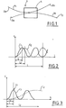
- Figure 1 is a schematic representation of the multiplexer according to the invention.
- FIG. 2 is a representation of the coupling rate proposed according to a technique of the prior art.
- FIG. 3 is a representation of the coupling rate of each of the waves as a function of the interaction length.
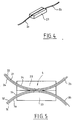
- Figure 4 is the representation of a fiber positioned in its support block.
- FIG. 5 is the representation of a multiplexer according to the invention produced with support blocks.
- the multiplexer 1 of the invention can be a fiber component or an integrated optical component produced for example on a glass or lithium niobate substrate or with silica guides on silicon substrate.
- the device of the invention is a multiplexer 1 comprising two optical fibers 2, 3 referenced 2a and 3a at the input, 2b and 3b at the output.
- a light wave of wavelength ⁇ 1 is coupled into the fiber 2a and an optical wave of wavelength ⁇ 2 is coupled into the fiber 3a.
- an optical wave of wavelength ⁇ 2 is coupled into the fiber 3a.
- the two waves of respective wavelengths ⁇ 1 and ⁇ 2 or at least most of the energy of these two waves are coupled to the fiber 3b.
- the fibers 2 and 3 each have a core respectively referenced 21 and 31 and an optical sheath referenced respectively 22 and 32.
- their mechanical protection is generally ensured by an external sheath which we will not consider here and which is not shown on the figures.
- the fibers 2 and 3 are shaped and maintained so that in the interaction zone 4 their respective hearts 21 and 31 are sufficiently close to each other so that a coupling by evanescent wave of the light waves coupled to each fibers, towards each other occurs.
- this approximation can be obtained by fusion welding and drawing. It can also be obtained by partial removal of the optical sheaths 22 and 32, holding the fibers in position in blocks 23 and 33 then bringing these blocks together. We will limit the description which follows to this latter embodiment.
- the blocks 23 and 33 are made of a material whose geometric properties are stable such as silica.
- each of these blocks a groove 24, 34 is formed, the section of which has a shape and a dimension such that it allows the fibers 21 and 31 to be positioned precisely in this groove.
- the section of this groove can have a shape of - U - or a shape of - V -.
- Each of these grooves has its central axis contained in a plane and a greater depth at the ends of the block than in the central part.
- the fibers 21 and 31 placed in these grooves 24 and 34 are close to each other in the vicinity of the centers of the blocks 21, 23 and 33.
- the depth of the grooves 24, 34 defines the curvature of the fibers in the interaction zone.
- the fibers 2 and 3 from which part of the optical sheath 22, 32 has been removed is flush with the surface of the blocks 23 and 33. This removal is carried out by lateral polishing.
- the contacting of the blocks 23 and 33 generates the contacting of the fibers, by their sheaths and defines an interaction zone.
- Such a device produces the coupling of the input waves by evanescent wave. More precisely, the light energy contained in the light wave, coupled at the input to one of the optical fibers is transferred, more or less completely, to the other fiber.
- the transfer rate shown in Figure 2 is a function of the interaction length of the fibers with respect to each other.
- This interaction length L is a function of the geometric parameters of the system, that is to say the distance h of the fibers, the offset d and the radii of curvature R1 and R2.
- the coupling rate c is defined as being the energy ratio between the outgoing flow by the optical fiber different from the input fiber over the coupled flow in the input fiber.
- This rate c varies sinusoidally as a function of the interaction length L.
- the length of interaction L1 is the smallest for which the coupling rate c is maximum.
- the coupling rate of the wave at wavelength ⁇ 1 is c1 and the coupling rate of the wave at length ⁇ 2 is c2.
- the coupling lengths L1 and L2 are close to each other on the other and it was proposed to carry out a multiplexer by choosing an interaction length L which is an even multiple of L1 and an odd multiple of L2.
- the energy of the light wave at the wavelength ⁇ 1 is maintained in the input fiber, that is to say in the first fiber, while the light energy of the wave at the length of ⁇ 2 wave is transferred from the input fiber (the second fiber) to the other fiber (the first).
- This determination of the interaction length can be carried out with a certain uncertainty and the adjustments which are necessary are therefore relatively simple and a good quality of the multiplexing can reasonably be obtained.
- optimization of the interaction length is achieved by relative displacement of the blocks 23 and 33 by means of mechanical precision movement and by observing the intensity of the outgoing flows by the fibers 2b and 3b.
- part of the optical sheath of the fibers 2 and 3 is removed after positioning the fiber in the block by polishing the assembly.
- the blocks 23 and 33 are preferably fixed relative to each other by gluing.
- an index liquid is interposed between the blocks 23 and 33 so as to improve the coupling.
- the multiplexer of the invention is used to amplify a light signal carried by the first optical wave at the wavelength ⁇ 1.
- the first fiber specially doped with rare earths is single mode at the wavelength ⁇ 1.
- the wave at wavelength ⁇ 2 is called the pump wave. It has a wavelength ⁇ 2 generally significantly less than the wavelength ⁇ 1, preferably ⁇ 1 is greater than or equal to 1.5 ⁇ 2.
- a pump wave with a wavelength equal to 0.532 ⁇ m, 0.820 ⁇ m or 0.980 ⁇ m can be used.
- optical fibers 2 and 3 are birefringent fibers.
Abstract
Description
L'invention concerne un multiplexeur en longueur d'onde.The invention relates to a wavelength multiplexer.
Le développement des fibres optiques, de l'optique intégrée, et de leurs applications dans le domaine de la transmission de données ou de la mesure rend nécessaire la conception et la mise au point de composants remplissant dans ces systèmes optiques les fonctions des composants optiques traditionnels.The development of optical fibers, integrated optics, and their applications in the field of data transmission or measurement necessitates the design and development of components fulfilling in these optical systems the functions of traditional optical components. .
Ainsi des multiplexeurs en longueur d'onde à fibre optique ont déjà été proposés. Ils permettent par exemple la transmission simultanée de différentes informations dans une même fibre.Thus optical fiber wavelength multiplexers have already been proposed. They allow for example the simultaneous transmission of different information in the same fiber.
Les demandes de brevet européen EP-0079.196 et EP-103.382 décrivent un tel multiplexeur réalisé avec deux fibres optiques monomodes.European patent applications EP-0079.196 and EP-103.382 describe such a multiplexer produced with two single-mode optical fibers.
Selon la technique décrite dans ces documents les coeurs des fibres sont placés à proximité l'un de l'autre dans une zone dite zone d'interaction.According to the technique described in these documents, the hearts of the fibers are placed close to one another in an area called the interaction area.
A cet effet une partie de la gaine optique de chacune de ces fibres est enlevée et chaque fibre est placée dans un bloc qui lui donne sa forme dans la zone d'interaction. La position relative des blocs détermine la position relative des coeurs.For this purpose, part of the optical sheath of each of these fibers is removed and each fiber is placed in a block which gives it its shape in the interaction zone. The relative position of the blocks determines the relative position of the hearts.
Dans la zone d'interaction est définie une longueur d'interaction qui dépend de l'épaisseur de la gaine optique de chaque fibre qui a été enlevée, des courbures respectives de chacune des fibres dans la zone d'interaction et de leur position relative.In the interaction zone is defined an interaction length which depends on the thickness of the optical cladding of each fiber which has been removed, the respective curvatures of each of the fibers in the interaction zone and their relative position.
Des ondes optiques de longueur d'onde respective λ₁ et λ₂ sont couplées dans les premières et deuxièmes fibres.Optical waves of respective wavelength λ₁ and λ₂ are coupled in the first and second fibers.
Pour un coupleur donné, il est également défini une longueur de couplage pour chaque longueur d'onde λ₁ et λ₂.For a given coupler, a coupling length is also defined for each wavelength λ₁ and λ₂.
Dans la zone d'interaction se produit un couplage de chaque onde, par onde évanescente qui engendre le passage de l'énergie lumineuse dans l'une ou l'autre fibre selon les valeurs relatives de la longueur de couplage par rapport à la longueur d'interaction.In the interaction zone, there is a coupling of each wave, by evanescent wave which generates the passage of light energy in one or the other fiber according to the relative values of the coupling length compared to the length d 'interaction.
La quantité relative d'énergie couplée dans chacune des fibres pour chaque longueur d'onde dépend des valeurs relatives, de la longueur d'interaction L, de la longueur de couplage L₁ à λ₁ et de la longueur de couplage L₂ à λ₂.The relative quantity of energy coupled into each of the fibers for each wavelength depends on the relative values, on the interaction length L, on the coupling length L₁ to λ₁ and on the coupling length L₂ to λ₂.
Selon le document cité plus haut il est proposé pour réaliser un multiplexeur, de fixer la longueur d'interaction à une valeur égale à un multiple pair de la longueur de couplage pour une des longueurs d'onde λ₁ par exemple et à un multiple impair de la longueur d'interaction l'autre longueur d'onde par exemple λ₂. Ainsi l'onde à la longueur d'onde λ₁ est maintenue dans sa fibre d'entrée et l'onde à la longueur d'onde λ₂ est transférée de sa fibre d'entrée à l'autre fibre.According to the document cited above, it is proposed to make a multiplexer, to set the interaction length to a value equal to an even multiple of the coupling length for one of the wavelengths λ₁ for example and to an odd multiple of the interaction length of the other wavelength, for example λ₂. Thus the wave at wavelength λ₁ is maintained in its input fiber and the wave at wavelength λ₂ is transferred from its input fiber to the other fiber.
Cette technique est performante et a permis de résoudre de nombreux problèmes. Toutefois il est apparu qu'elle est mal adaptée à des situations dans lesquelles les longueurs d'onde λ₁ et λ₂ concernées sont très différentes ou lorsqu'il est nécessaire de réaliser un dispositif de multiplexage alors que l'une au moins des fibres optiques n'est pas monomode.This technique is effective and has solved many problems. However, it has become apparent that it is ill-suited to situations in which the wavelengths λ₁ and λ₂ concerned are very different or when it is necessary to produce a multiplexing device when at least one of the optical fibers is not monomode.
Par ailleurs le brevet US-A-4, 963, 832 décrit un dispositif de couplage pour amplificateur à fibre optique dopées à l'Erbium. Un coupleur dichroïque permet d'éviter le couplage de signal de pompe vers la fibre de transmision.Furthermore, US Pat. No. 4,963,832 describes a coupling device for an Erbium-doped optical fiber amplifier. A dichroic coupler avoids coupling of the pump signal to the transmission fiber.
Le but de la présente invention est la réalisation d'un multiplexeur en longueur d'onde utilisable pour le couplage d'onde à des longueurs d'onde très différentes et supportant, que, à l'entrée les guides ne soient pas monomodes pour la longueur d'onde la plus faible.The object of the present invention is the production of a wavelength multiplexer which can be used for coupling the wave at very different wavelengths and supporting, that, at the input, the guides are not monomode for the lowest wavelength.
A cet effet l'invention concerne un multiplexeur en longueur d'onde, à guides d'onde optiques par couplage d'ondes évanescentes, de deux ondes optiques d'entrée de longueur d'onde respectives λ₁ et λ₂ comportant un premier guide optique monomode à la longueur d'onde λ₁ et un deuxième guide optique guidant l'onde d'entrée de longueur d'onde λ₂ les premier et deuxième guides ayant un coeur et une gaine optique et convergeant dans une zone d'interaction, les coeurs des premier et deuxième guides étant à proximité l'un de l'autre et définissant une longueur d'interaction et des longueurs de couplage pour chaque longueur d'onde λ₁, λ₂.To this end the invention relates to a wavelength multiplexer, with optical waveguides by coupling of evanescent waves, of two input optical waves of respective wavelength λ₁ and λ₂ comprising a first single-mode optical guide at the wavelength λ₁ and a second optical guide guiding the input wave of wavelength λ₂ the first and second guides having a core and an optical sheath and converging in an interaction zone, the hearts of the first and second guides being close to each other and defining an interaction length and coupling lengths for each wavelength λ₁, λ₂.
Selon l'invention λ₁ est supérieur à λ₂ et la longueur d'interaction est égale à la longueur de couplage pour λ₁.According to the invention λ₁ is greater than λ₂ and the interaction length is equal to the coupling length for λ₁.
Dans un mode de réalisation préféré les guides optiques sont des fibres.In a preferred embodiment the optical guides are fibers.
Elles sont avantageusement biréfringentes ; selon un autre mode de réalisation l'une des fibres est dopée, l'onde à la longueur d'onde λ₁ est porteuse d'un signal et l'onde à la longueur d'onde λ₂ est une onde de pompe.They are advantageously birefringent; according to another embodiment, one of the fibers is doped, the wave at the wavelength λ₁ carries a signal and the wave at the wavelength λ₂ is a pump wave.
L'invention sera décrite plus en détail dans la description qui va suivre en références aux dessins dans lesquels :The invention will be described in more detail in the description which follows with reference to the drawings in which:
La figure 1 est une représentation schématique du multiplexeur selon l'invention.Figure 1 is a schematic representation of the multiplexer according to the invention.
La figure 2 est une représentation du taux de couplage proposé selon une technique de l'art antérieur.FIG. 2 is a representation of the coupling rate proposed according to a technique of the prior art.
La figure 3 est une représentation du taux de couplage de chacune des ondes en fonction de la longueur d'interaction.FIG. 3 is a representation of the coupling rate of each of the waves as a function of the interaction length.
La figure 4 est la représentation d'une fibre positionnée dans son bloc support.Figure 4 is the representation of a fiber positioned in its support block.
La figure 5 est la représentation d'un multiplexeur selon l'invention réalisé avec des blocs supports.FIG. 5 is the representation of a multiplexer according to the invention produced with support blocks.
Le multiplexeur 1 de l'invention peut être un composant à fibres ou un composant d'optique intégrée réalisé par exemple sur un substrat en verre ou en niobate de lithium ou avec des guides de silice sur substrat silicium.The
Dans la description d'un mode de réalisation particulier qui suit, le dispositif de l'invention est un multiplexeur 1 comportant deux fibres optiques 2, 3 référencé 2a et 3a à l'entrée, 2b et 3b à la sortie.In the description of a particular embodiment which follows, the device of the invention is a
A l'entrée une onde lumineuse de longueur d'onde λ₁ est couplée dans la fibre 2a et une onde optique de longueur d'onde λ₂ est couplée dans la fibre 3a. A la sortie les deux ondes de longueurs d'onde respectives λ₁ et λ₂ ou au moins l'essentiel de l'énergie de ces deux ondes sont couplées à la fibre 3b.At the input, a light wave of wavelength λ₁ is coupled into the
Les fibres 2 et 3 comportent chacune un coeur respectivement référencé 21 et 31 et une gaine optique référencée respectivement 22 et 32. De plus leur protection mécanique est généralement assurée par une gaine extérieure que nous ne considérerons pas ici et qui n'est pas représentée sur les figures.The
Les fibres 2 et 3 sont façonnées et maintenues de telle sorte que dans la zone d'interaction 4 leurs coeurs respectifs 21 et 31 soient suffisamment rapprochés l'un de l'autre pour qu'un couplage par onde évanescente des ondes lumineuses couplées à chacune des fibres, vers l'autre se produise.The
Différentes méthodes permettent d'obtenir et de contrôler le rapprochement des coeurs 21 et 31, ce sont celles qui sont connues et utilisées de manière générale dans la fabrication des coupleurs à fibre optique.Different methods make it possible to obtain and control the approximation of the
En particulier ce rapprochement peut être obtenu par soudure par fusion et étirage. Il peut également être obtenu par enlèvement partiel des gaines optiques 22 et 32, maintien des fibres en position dans des blocs 23 et 33 puis rapprochement de ces blocs. Nous limiterons la description qui va suivre à ce dernier mode de réalisation.In particular, this approximation can be obtained by fusion welding and drawing. It can also be obtained by partial removal of the
Les blocs 23 et 33 sont réalisés dans un matériau dont les propriétés géométriques sont stables telles que la silice.The
Dans chacun de ces blocs une rainure 24, 34 est formée dont la section a une forme et une dimension telle qu'elle permet de positionner les fibres 21 et 31 avec précision dans cette rainure.In each of these blocks a
La section de cette rainure peut avoir une forme de - U - ou une forme de - V -.The section of this groove can have a shape of - U - or a shape of - V -.
Chacune de ces rainures a son axe central contenu dans un plan et une profondeur plus importante aux extrémités du bloc que dans la partie centrale. Ainsi les fibres 21 et 31 placées dans ces rainures 24 et 34 sont proches l'une de l'autre au voisinage des centres des blocs 21, 23 et 33.Each of these grooves has its central axis contained in a plane and a greater depth at the ends of the block than in the central part. Thus the
La profondeur des rainures 24, 34 définit la courbure des fibres dans la zone d'interaction.The depth of the
Plus précisément dans la zone d'interaction 4 les fibres 2 et 3 dont une partie de la gaine optique 22, 32 a été enlevée affleure à la surface des blocs 23 et 33. Cet enlèvement est réalisé par polissage latéral.More precisely in the
Ainsi la mise en contact des blocs 23 et 33 engendre la mise en contact des fibres, par leurs gaines et définit une zone d'interaction.Thus the contacting of the
La longueur d'interaction dans la zone d'interaction 4 est définie par la distance h des coeurs 21 et 31 des fibres, par les rayons de courbure R1 et R2 des fibres dans cette zone (on choisira en général R2 = R1 = R) et par le décalage latéral d qu'il est possible de faire varier en faisant glisser les blocs 23 et 33 relativement l'un par rapport à l'autre.The interaction length in the
Un tel dispositif produit le couplage des ondes d'entrée par onde évanescente. Plus précisément l'énergie lumineuse contenue dans l'onde lumineuse, couplée à l'entrée à l'une des fibres optiques est transférée, plus ou moins complètement dans l'autre fibre.Such a device produces the coupling of the input waves by evanescent wave. More precisely, the light energy contained in the light wave, coupled at the input to one of the optical fibers is transferred, more or less completely, to the other fiber.
Le taux de transfert représenté à la figure 2 est fonction de la longueur d'interaction des fibres l'une par rapport à l'autre.The transfer rate shown in Figure 2 is a function of the interaction length of the fibers with respect to each other.
Cette longueur d'interaction L est fonction des paramètres géométriques du système c'est-à-dire de la distance h des fibres, du décalage d et des rayons de courbure R1 et R2.This interaction length L is a function of the geometric parameters of the system, that is to say the distance h of the fibers, the offset d and the radii of curvature R1 and R2.
Le taux de couplage c est défini comme étant le rapport en énergie entre le flux sortant par la fibre optique différente de la fibre d'entrée sur le flux couplé dans la fibre d'entrée.The coupling rate c is defined as being the energy ratio between the outgoing flow by the optical fiber different from the input fiber over the coupled flow in the input fiber.
Ce taux c varie sinusoïdalement en fonction de la longueur d'interaction L. On appelle longueur de couplage la longueur interaction L₁ la plus petite pour laquelle le taux de couplage c est maximum.This rate c varies sinusoidally as a function of the interaction length L. The length of interaction L₁ is the smallest for which the coupling rate c is maximum.
Dans le système décrit plus haut le taux de couplage de l'onde à la longueur d'onde λ₁ est c1 et le taux de couplage de l'onde à la longueur λ₂ est c2.In the system described above, the coupling rate of the wave at wavelength λ₁ is c1 and the coupling rate of the wave at length λ₂ is c2.
Lorsque, selon l'art antérieur, telles que représentées sur la figure 2 les longueurs d'onde λ₁ et λ₂ sont relativement proches, et que les deux fibres 2 et 3 sont monomodes, les longueurs de couplage L₁ et L₂ sont proches l'une de l'autre et il a été proposé de réaliser un multiplexeur en choisissant une longueur d'interaction L qui soit un multiple pair de L₁ et un multiple impair de L₂.When, according to the prior art, as shown in FIG. 2, the wavelengths λ₁ and λ₂ are relatively close, and the two
Ainsi l'énergie de l'onde lumineuse à la longueur d'onde λ₁ est maintenue dans la fibre d'entrée c'est-à-dire dans la première fibre alors que l'énergie lumineuse de l'onde à la longueur d'onde λ₂ est transférée de la fibre d'entrée (la deuxième fibre) vers l'autre fibre (la première).Thus the energy of the light wave at the wavelength λ₁ is maintained in the input fiber, that is to say in the first fiber, while the light energy of the wave at the length of λ₂ wave is transferred from the input fiber (the second fiber) to the other fiber (the first).
Selon l'invention, telle que représentée sur la figure 3 lorsque les longueurs d'onde λ₁ et λ₂ sont très différentes et que l'une des fibres n'est pas monomode la condition mentionnée plus haut est difficile à satisfaire.According to the invention, as shown in FIG. 3 when the wavelengths λ₁ and λ₂ are very different and one of the fibers is not single-mode, the condition mentioned above is difficult to satisfy.
Par contre il a été trouvé de manière surprenante que pour une valeur L de la longueur d'interaction égale à la longueur de couplage L₁ de la plus grande longueur d'onde λ₁ l'ensemble du flux à cette longueur d'onde λ₁ est couplé alors que l'essentiel du flux à la longueur d'onde λ₂ inférieure, reste dans sa fibre.On the other hand, it was surprisingly found that for a value L of the interaction length equal to the coupling length L₁ of the longest wavelength λ₁ the entire flux at this wavelength λ₁ is coupled while most of the flux at the lower wavelength λ₂ remains in its fiber.
Cette détermination de la longueur d'interaction peut être réalisée avec une certaine incertitude et les réglages qui sont nécessaires sont donc relativement simples et une bonne qualité du multiplexage peut raisonnablement être obtenue.This determination of the interaction length can be carried out with a certain uncertainty and the adjustments which are necessary are therefore relatively simple and a good quality of the multiplexing can reasonably be obtained.
L'optimisation de la longueur d'interaction est réalisée par déplacement relatif des blocs 23 et 33 par l'intermédiaire de mouvement mécanique de précision et en observant l'intensité des flux sortants par les fibres 2b et 3b.Optimization of the interaction length is achieved by relative displacement of the
De préférence l'enlèvement d'une partie de la gaine optique des fibres 2 et 3 est réalisée après positionnement de la fibre dans le bloc par polissage de l'ensemble.Preferably, part of the optical sheath of the
Après l'optimisation de la longueur d'interaction L les blocs 23 et 33 sont préférentiellement fixés l'un par rapport à l'autre par collage.After optimizing the interaction length L, the
Dans un autre mode de réalisation un liquide d'indice est interposé entre les blocs 23 et 33 de manière à améliorer le couplage.In another embodiment, an index liquid is interposed between the
Dans un mode de réalisation préféré le multiplexeur de l'invention est utilisé pour amplifier un signal lumineux porté par la première onde optique à la longueur d'onde λ₁.In a preferred embodiment, the multiplexer of the invention is used to amplify a light signal carried by the first optical wave at the wavelength λ₁.
A cet effet la première fibre spécialement dopée avec des terres rares est monomode à la longueur d'onde λ₁.For this purpose, the first fiber specially doped with rare earths is single mode at the wavelength λ₁.
L'onde à la longueur d'onde λ₂ est appelée onde de pompe. Elle a une longueur d'onde λ₂ généralement notablement inférieure à la longueur d'onde λ₁, de préférence λ₁ est supérieur ou égal à 1,5 λ₂.The wave at wavelength λ₂ is called the pump wave. It has a wavelength λ₂ generally significantly less than the wavelength λ₁, preferably λ₁ is greater than or equal to 1.5 λ₂.
A titre d'exemple pour une onde λ₁ à la longueur d'onde 1,55 µm il peut être utilisé une onde de pompe de longueur d'onde égale à 0,532 µm, 0,820 µm ou 0,980 µm.For example, for a λ₁ wave at the wavelength 1.55 µm, a pump wave with a wavelength equal to 0.532 µm, 0.820 µm or 0.980 µm can be used.
Dans un mode de réalisation préférée les fibres optiques 2 et 3 sont des fibres biréfringentes.In a preferred embodiment the
De bons résultats sont obtenus lorsque les fibres 2 et 3 sont identiques c'est-à-dire que la deuxième fibre 3 est monomode à la longueur d'onde λ₁.Good results are obtained when the
Claims (9)
λ₁ est supérieur à λ₂ et la longueur d'intéraction est égale à la longueur de couplage pour λ₁.Wavelength multiplexer, with optical waveguides by coupling of evanescent waves, of two input optical waves of respective wavelength λ₁, and λ₂ comprising a first monomode optical guide (2a) at length d λ₁ wave and a second optical guide (2b) guiding the input wavelength λ₂ the first and second guides having an optical core and sheath and converging in an interaction zone, the hearts of the first and second guides being close to each other and defining an interaction length and coupling lengths for each wavelength λ₁, λ₂ characterized in that:
λ₁ is greater than λ₂ and the interaction length is equal to the coupling length for λ₁.
Applications Claiming Priority (2)
| Application Number | Priority Date | Filing Date | Title |
|---|---|---|---|
| FR9013663A FR2668868B1 (en) | 1990-11-05 | 1990-11-05 | WAVELENGTH MULTIPLEXER. |
| FR9013663 | 1990-11-05 |
Publications (1)
| Publication Number | Publication Date |
|---|---|
| EP0485276A1 true EP0485276A1 (en) | 1992-05-13 |
Family
ID=9401841
Family Applications (1)
| Application Number | Title | Priority Date | Filing Date |
|---|---|---|---|
| EP91402962A Withdrawn EP0485276A1 (en) | 1990-11-05 | 1991-11-05 | Wavelength multiplexer |
Country Status (4)
| Country | Link |
|---|---|
| EP (1) | EP0485276A1 (en) |
| JP (1) | JPH06201944A (en) |
| CA (1) | CA2054904A1 (en) |
| FR (1) | FR2668868B1 (en) |
Citations (4)
| Publication number | Priority date | Publication date | Assignee | Title |
|---|---|---|---|---|
| EP0103382A2 (en) * | 1982-08-11 | 1984-03-21 | The Board Of Trustees Of The Leland Stanford Junior University | Fiber optic amplifier |
| US4834481A (en) * | 1985-11-12 | 1989-05-30 | Gould Inc. | In-line single-mode fiber optic multiplexer/demultiplexer |
| EP0322744A2 (en) * | 1987-12-25 | 1989-07-05 | Hitachi, Ltd. | Optical waveguide device |
| US4963832A (en) * | 1989-08-08 | 1990-10-16 | At&T Bell Laboratories | Erbium-doped fiber amplifier coupling device |
-
1990
- 1990-11-05 FR FR9013663A patent/FR2668868B1/en not_active Expired - Fee Related
-
1991
- 1991-11-04 CA CA 2054904 patent/CA2054904A1/en not_active Abandoned
- 1991-11-05 EP EP91402962A patent/EP0485276A1/en not_active Withdrawn
- 1991-11-05 JP JP34935391A patent/JPH06201944A/en active Pending
Patent Citations (4)
| Publication number | Priority date | Publication date | Assignee | Title |
|---|---|---|---|---|
| EP0103382A2 (en) * | 1982-08-11 | 1984-03-21 | The Board Of Trustees Of The Leland Stanford Junior University | Fiber optic amplifier |
| US4834481A (en) * | 1985-11-12 | 1989-05-30 | Gould Inc. | In-line single-mode fiber optic multiplexer/demultiplexer |
| EP0322744A2 (en) * | 1987-12-25 | 1989-07-05 | Hitachi, Ltd. | Optical waveguide device |
| US4963832A (en) * | 1989-08-08 | 1990-10-16 | At&T Bell Laboratories | Erbium-doped fiber amplifier coupling device |
Non-Patent Citations (1)
| Title |
|---|
| ELECTRONICS LETTERS. vol. 21, no. 10, Mai 1985, STEVENAGE GB pages 415 - 416; J. YOKOHAMA ET AL.: 'Fibre-optic polarising beam splitter employing birefringent-fibre coupler' * |
Also Published As
| Publication number | Publication date |
|---|---|
| JPH06201944A (en) | 1994-07-22 |
| CA2054904A1 (en) | 1992-05-06 |
| FR2668868B1 (en) | 1993-06-18 |
| FR2668868A1 (en) | 1992-05-07 |
Similar Documents
| Publication | Publication Date | Title |
|---|---|---|
| FR2537733A1 (en) | OPTICAL WAVEGUIDE DEVICE | |
| EP2286289B1 (en) | Device for coupling an optical fibre and a nanophotonic component | |
| EP0825464B1 (en) | Process of manufacturing and assembling a collective optical coupling device onto the end of a bundle of several monomode optical fibers | |
| EP0005093B1 (en) | Optical demultiplexing integrated circuit and process for the manufacture of this circuit | |
| EP0220439A2 (en) | Expanded end optical fiber and associated coupling arrangements | |
| EP0196948A1 (en) | Reversible demultiplexing device of a plurality of light signals in integrated optics | |
| FR2595477A1 (en) | OPTICAL DEMULTIPLEXING / MULTIPLEXING CIRCUIT | |
| FR2544883A1 (en) | OPTICAL MULTIPLEXER / DEMULTIPLEXER | |
| EP0069054A2 (en) | Optical-fibre coupling apparatus, and method of production thereof | |
| EP0346232B1 (en) | Process and system for joining optical fibres without Fresnel-reflection, variable optical attenuator and system, using the same for measurement of the influence of the reflection-rate on an optical line | |
| US20110110629A1 (en) | Planar optical waveguide | |
| EP0665615B1 (en) | Fluoride glass optical amplifier and method for its manufacture | |
| CA2160217C (en) | Wavelength selective optical coupler | |
| EP0485276A1 (en) | Wavelength multiplexer | |
| JPS61282803A (en) | Optical multiplexing and demultiplexing device | |
| FR2794534A1 (en) | OPTICAL MULTIPLEXER / DEMULTIPLEXER WITH THREE WAVEGUIDES | |
| FR2731573A1 (en) | Optical multiplexer-demultiplexer e.g. for telephone signals | |
| EP0703475A1 (en) | Wavelength selective optical coupler with multicore optical fiber | |
| EP1538469B1 (en) | Photosensitive optical waveguide | |
| EP1359442B1 (en) | Apodised complex filter | |
| EP1151334B1 (en) | Line attenuation device for monomode fibres and associated method for the production thereof | |
| EP1433006B1 (en) | Optical component with spectral separation | |
| Reichelt et al. | Wavelength-division multi demultiplexers for two-channel single-mode transmission systems | |
| FR2756055A1 (en) | MULTIMODE OPTICAL COUPLER AND METHOD FOR MANUFACTURING THE SAME | |
| US20240061177A1 (en) | Multichannel optical tap devices |
Legal Events
| Date | Code | Title | Description |
|---|---|---|---|
| PUAI | Public reference made under article 153(3) epc to a published international application that has entered the european phase |
Free format text: ORIGINAL CODE: 0009012 |
|
| AK | Designated contracting states |
Kind code of ref document: A1 Designated state(s): DE GB IT NL |
|
| 17P | Request for examination filed |
Effective date: 19920810 |
|
| 17Q | First examination report despatched |
Effective date: 19940722 |
|
| STAA | Information on the status of an ep patent application or granted ep patent |
Free format text: STATUS: THE APPLICATION IS DEEMED TO BE WITHDRAWN |
|
| 18D | Application deemed to be withdrawn |
Effective date: 19950202 |