EP0485293A2 - Image processing system - Google Patents
Image processing system Download PDFInfo
- Publication number
- EP0485293A2 EP0485293A2 EP91402995A EP91402995A EP0485293A2 EP 0485293 A2 EP0485293 A2 EP 0485293A2 EP 91402995 A EP91402995 A EP 91402995A EP 91402995 A EP91402995 A EP 91402995A EP 0485293 A2 EP0485293 A2 EP 0485293A2
- Authority
- EP
- European Patent Office
- Prior art keywords
- image information
- processing system
- image processing
- image
- output
- Prior art date
- Legal status (The legal status is an assumption and is not a legal conclusion. Google has not performed a legal analysis and makes no representation as to the accuracy of the status listed.)
- Granted
Links
Images


Classifications
-
- H—ELECTRICITY
- H04—ELECTRIC COMMUNICATION TECHNIQUE
- H04N—PICTORIAL COMMUNICATION, e.g. TELEVISION
- H04N1/00—Scanning, transmission or reproduction of documents or the like, e.g. facsimile transmission; Details thereof
- H04N1/00127—Connection or combination of a still picture apparatus with another apparatus, e.g. for storage, processing or transmission of still picture signals or of information associated with a still picture
- H04N1/00281—Connection or combination of a still picture apparatus with another apparatus, e.g. for storage, processing or transmission of still picture signals or of information associated with a still picture with a telecommunication apparatus, e.g. a switched network of teleprinters for the distribution of text-based information, a selective call terminal
- H04N1/00283—Connection or combination of a still picture apparatus with another apparatus, e.g. for storage, processing or transmission of still picture signals or of information associated with a still picture with a telecommunication apparatus, e.g. a switched network of teleprinters for the distribution of text-based information, a selective call terminal with a television apparatus
- H04N1/00286—Connection or combination of a still picture apparatus with another apparatus, e.g. for storage, processing or transmission of still picture signals or of information associated with a still picture with a telecommunication apparatus, e.g. a switched network of teleprinters for the distribution of text-based information, a selective call terminal with a television apparatus with studio circuitry, devices or equipment, e.g. television cameras
-
- G—PHYSICS
- G07—CHECKING-DEVICES
- G07F—COIN-FREED OR LIKE APPARATUS
- G07F17/00—Coin-freed apparatus for hiring articles; Coin-freed facilities or services
- G07F17/02—Coin-freed apparatus for hiring articles; Coin-freed facilities or services for optical devices, e.g. telescopes
-
- G—PHYSICS
- G07—CHECKING-DEVICES
- G07F—COIN-FREED OR LIKE APPARATUS
- G07F17/00—Coin-freed apparatus for hiring articles; Coin-freed facilities or services
- G07F17/26—Coin-freed apparatus for hiring articles; Coin-freed facilities or services for printing, stamping, franking, typing or teleprinting apparatus
-
- H—ELECTRICITY
- H04—ELECTRIC COMMUNICATION TECHNIQUE
- H04N—PICTORIAL COMMUNICATION, e.g. TELEVISION
- H04N1/00—Scanning, transmission or reproduction of documents or the like, e.g. facsimile transmission; Details thereof
- H04N1/00002—Diagnosis, testing or measuring; Detecting, analysing or monitoring not otherwise provided for
- H04N1/00071—Diagnosis, testing or measuring; Detecting, analysing or monitoring not otherwise provided for characterised by the action taken
- H04N1/00074—Indicating or reporting
- H04N1/00076—Indicating or reporting locally
-
- H—ELECTRICITY
- H04—ELECTRIC COMMUNICATION TECHNIQUE
- H04N—PICTORIAL COMMUNICATION, e.g. TELEVISION
- H04N1/00—Scanning, transmission or reproduction of documents or the like, e.g. facsimile transmission; Details thereof
- H04N1/00002—Diagnosis, testing or measuring; Detecting, analysing or monitoring not otherwise provided for
- H04N1/00071—Diagnosis, testing or measuring; Detecting, analysing or monitoring not otherwise provided for characterised by the action taken
- H04N1/00074—Indicating or reporting
- H04N1/00079—Indicating or reporting remotely
-
- H—ELECTRICITY
- H04—ELECTRIC COMMUNICATION TECHNIQUE
- H04N—PICTORIAL COMMUNICATION, e.g. TELEVISION
- H04N1/00—Scanning, transmission or reproduction of documents or the like, e.g. facsimile transmission; Details thereof
- H04N1/00127—Connection or combination of a still picture apparatus with another apparatus, e.g. for storage, processing or transmission of still picture signals or of information associated with a still picture
- H04N1/00281—Connection or combination of a still picture apparatus with another apparatus, e.g. for storage, processing or transmission of still picture signals or of information associated with a still picture with a telecommunication apparatus, e.g. a switched network of teleprinters for the distribution of text-based information, a selective call terminal
- H04N1/00283—Connection or combination of a still picture apparatus with another apparatus, e.g. for storage, processing or transmission of still picture signals or of information associated with a still picture with a telecommunication apparatus, e.g. a switched network of teleprinters for the distribution of text-based information, a selective call terminal with a television apparatus
- H04N1/00286—Connection or combination of a still picture apparatus with another apparatus, e.g. for storage, processing or transmission of still picture signals or of information associated with a still picture with a telecommunication apparatus, e.g. a switched network of teleprinters for the distribution of text-based information, a selective call terminal with a television apparatus with studio circuitry, devices or equipment, e.g. television cameras
- H04N1/00289—Connection or combination of a still picture apparatus with another apparatus, e.g. for storage, processing or transmission of still picture signals or of information associated with a still picture with a telecommunication apparatus, e.g. a switched network of teleprinters for the distribution of text-based information, a selective call terminal with a television apparatus with studio circuitry, devices or equipment, e.g. television cameras in a video photo booth or the like
-
- H—ELECTRICITY
- H04—ELECTRIC COMMUNICATION TECHNIQUE
- H04N—PICTORIAL COMMUNICATION, e.g. TELEVISION
- H04N1/00—Scanning, transmission or reproduction of documents or the like, e.g. facsimile transmission; Details thereof
- H04N1/0035—User-machine interface; Control console
- H04N1/00405—Output means
- H04N1/00408—Display of information to the user, e.g. menus
-
- H—ELECTRICITY
- H04—ELECTRIC COMMUNICATION TECHNIQUE
- H04N—PICTORIAL COMMUNICATION, e.g. TELEVISION
- H04N1/00—Scanning, transmission or reproduction of documents or the like, e.g. facsimile transmission; Details thereof
- H04N1/0035—User-machine interface; Control console
- H04N1/00405—Output means
- H04N1/00485—Output means providing a hardcopy output to the user, e.g. print out
-
- H—ELECTRICITY
- H04—ELECTRIC COMMUNICATION TECHNIQUE
- H04N—PICTORIAL COMMUNICATION, e.g. TELEVISION
- H04N1/00—Scanning, transmission or reproduction of documents or the like, e.g. facsimile transmission; Details thereof
- H04N1/32—Circuits or arrangements for control or supervision between transmitter and receiver or between image input and image output device, e.g. between a still-image camera and its memory or between a still-image camera and a printer device
- H04N1/32358—Circuits or arrangements for control or supervision between transmitter and receiver or between image input and image output device, e.g. between a still-image camera and its memory or between a still-image camera and a printer device using picture signal storage, e.g. at transmitter
- H04N1/32486—Storage for making a plurality of copies or reproductions
-
- H—ELECTRICITY
- H04—ELECTRIC COMMUNICATION TECHNIQUE
- H04N—PICTORIAL COMMUNICATION, e.g. TELEVISION
- H04N1/00—Scanning, transmission or reproduction of documents or the like, e.g. facsimile transmission; Details thereof
- H04N1/387—Composing, repositioning or otherwise geometrically modifying originals
- H04N1/3872—Repositioning or masking
- H04N1/3873—Repositioning or masking defined only by a limited number of coordinate points or parameters, e.g. corners, centre; for trimming
-
- H—ELECTRICITY
- H04—ELECTRIC COMMUNICATION TECHNIQUE
- H04N—PICTORIAL COMMUNICATION, e.g. TELEVISION
- H04N7/00—Television systems
- H04N7/18—Closed-circuit television [CCTV] systems, i.e. systems in which the video signal is not broadcast
-
- H—ELECTRICITY
- H04—ELECTRIC COMMUNICATION TECHNIQUE
- H04N—PICTORIAL COMMUNICATION, e.g. TELEVISION
- H04N2201/00—Indexing scheme relating to scanning, transmission or reproduction of documents or the like, and to details thereof
- H04N2201/0077—Types of the still picture apparatus
- H04N2201/0082—Image hardcopy reproducer
-
- H—ELECTRICITY
- H04—ELECTRIC COMMUNICATION TECHNIQUE
- H04N—PICTORIAL COMMUNICATION, e.g. TELEVISION
- H04N2201/00—Indexing scheme relating to scanning, transmission or reproduction of documents or the like, and to details thereof
- H04N2201/0077—Types of the still picture apparatus
- H04N2201/0084—Digital still camera
-
- H—ELECTRICITY
- H04—ELECTRIC COMMUNICATION TECHNIQUE
- H04N—PICTORIAL COMMUNICATION, e.g. TELEVISION
- H04N2201/00—Indexing scheme relating to scanning, transmission or reproduction of documents or the like, and to details thereof
- H04N2201/0077—Types of the still picture apparatus
- H04N2201/0087—Image storage device
-
- H—ELECTRICITY
- H04—ELECTRIC COMMUNICATION TECHNIQUE
- H04N—PICTORIAL COMMUNICATION, e.g. TELEVISION
- H04N2201/00—Indexing scheme relating to scanning, transmission or reproduction of documents or the like, and to details thereof
- H04N2201/0077—Types of the still picture apparatus
- H04N2201/0089—Image display device
-
- Y—GENERAL TAGGING OF NEW TECHNOLOGICAL DEVELOPMENTS; GENERAL TAGGING OF CROSS-SECTIONAL TECHNOLOGIES SPANNING OVER SEVERAL SECTIONS OF THE IPC; TECHNICAL SUBJECTS COVERED BY FORMER USPC CROSS-REFERENCE ART COLLECTIONS [XRACs] AND DIGESTS
- Y10—TECHNICAL SUBJECTS COVERED BY FORMER USPC
- Y10S—TECHNICAL SUBJECTS COVERED BY FORMER USPC CROSS-REFERENCE ART COLLECTIONS [XRACs] AND DIGESTS
- Y10S358/00—Facsimile and static presentation processing
- Y10S358/906—Hand-held camera with recorder in a single unit
Definitions
- the present invention relates to an image processing system for photographing an object and printing a photographed image.
- photo booth apparatuses for automatically taking a picture for the identification card or passport with the input of a coin, in which the apparatus comprises a camera, a photo developing unit and a flash with the optical silver salt photography.
- the present invention was achieved in view of the above-mentioned respects, and its object is to provide an improved image processing apparatus.
- an object of the present invention to provide an image processing system which is always available to the user, and capable of rapid processing.
- an object of the present invention to provide an image processing system capable of printing both the color and black-and-white pictures.
- Fig. 1 is a block diagram of an image processing system in an example of the present invention.
- Fig. 2 is an external view of the image processing system in the example.
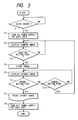
- Fig. 3 is a flowchart of the operation in a system control unit 16 as shown in Fig. 1.
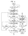
- Fig. 4 is a flowchart of another operation in the system control unit 16 as shown in Fig. 1.
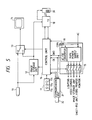
- Fig. 5 is a block diagram of an image processing system in another example.
- Fig. 6 is a block diagram of a centralized supervisory system for making the centralized supervision of a plurality of image processing system.
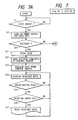
- Fig. 7 is a flowchart of the operation in a system control unit 16 as shown in Fig. 5.
- Fig. 8 is a table showing the signals indicating the states of a printer 18 as shown in Fig. 5.
- Fig. 9 is a specific circuit diagram of a communication unit 31 as shown in Fig. 5.
- Fig. 10 is a block diagram of an image processing system in another example.
- Fig. 11 is a flowchart of the operation in a system control unit 16 as shown in Fig. 10.
- Fig. 12 is a view showing a mark indicating a print region displayed on a monitor 14.
- Fig. 13 is a flowchart of the printing as shown in Fig. 10.
- Fig. 14 is a view showing a result printed with a region specification as shown in Fig. 12.
- Fig. 15 is a block diagram of an image processing system in another example.
- Fig. 16 is a flowchart of the operation in a system control unit 16 as shown in Fig. 15.
- Fig. 17 is a view showing a display screen on a monitor 14.
- Fig. 18 is a block diagram of an image processing system in another example.
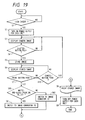
- Fig. 19 is a flowchart of the operation in a system control unit 16 as shown in Fig. 18.
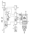
- Fig. 20 is a block diagram of an image processing system in another example.
- Fig. 21 is a block diagram of an image processing system in another example.
- Fig. 22 is a configuration view of a rotation filter 75 as shown in Fig. 21.
- Fig. 23 is a flowchart of the image pick-up as shown in Fig. 21.
- Fig. 24 is a block diagram of an image processing system in another example.
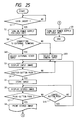
- Fig. 25 is a flowchart of the operation in a system control unit 16 as shown in Fig. 24.
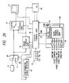
- Fig. 26 is a block diagram of an image processing system in another embodiment.
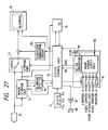
- Fig. 27 is a block diagram of an image processing system in another embodiment.
- Fig. 28 is a view showing the movement of an image in the time direction.
- Fig. 29 is a view showing a blurred image displayed on the monitor 14.
- Fig. 30 is a view showing the blurred image printed by a printer 18.
- Fig. 31 is a view showing the image stored in a first field of image storage unit 12.
- Fig. 32 is a view showing the image stored in a second field of image storage unit 12.
- Fig. 33 is a flowchart of the operation in a system control unit 16 as shown in Fig. 27.
- Fig. 34 is a flowchart of the operation in the system control unit 16 as shown in Fig. 27.
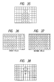
- Fig. 35 is a view showing detected movement vectors.
- Fig. 36 is a view showing the image in the first field after the correction for the blurring.
- Fig. 37 is a view showing the image in the second field after correction for the blurring.
- Fig. 38 is a view showing a printed image image after the correction for the blurring.
- Fig. 1 is a block diagram of an image processing system in one example of the present invention.
- 11 is an image pick-up unit consisting of a video camera
- 12 is an image storage unit constituted of a semiconductor memory, for example, for storing the image information from the video camera 11
- 13 is a monitor output screen changeover switch
- 14 is a monitor
- 15 is a power supply unit for supplying the power to each unit.
- 16 is a system control unit for controlling the operation of each unit, which is constituted of CPU, RAM, and ROM (not shown).
- the RAM is used as a work area for the CPU, and the ROM has written the contents of control operation or the message data to be displayed on the monitor.
- 17 is an operation unit for operating the system control unit, comprising a shutter button 17a for starting the storage of image, a print button 17b for starting the print of stored image, and a cancel button 17c for cancelling the stored image to reset the system to a photographing wait state.
- 18 is a video printer such as a thermal printer, or a bubble jet printer for discharging the ink by the use of the pressure of bubbles generated by the heat.
- 19 is a detector for detecting the input of a coin.
- Fig. 2 is an external view of this example.
- 20 is a lighting for lighting an object, such as a fluorescent lamp.
- 21 is a coin slot.
- FIG. 3 A flowchart of the operation in the system control unit 16 of an electronic photo system having the above configuration is shown in Fig. 3.
- a coin insertion signal is sent to the system control unit 16 (step S1).
- the system control unit 16 which has received the coin insertion signal sends a signal to the power supply unit 15 to start the supply of the electric power to each unit (step S2).
- the switch 13 is changed to the camera side to display an image being currently picked up directly on the monitor 14 (step S3).
- the shutter button 17a of the operation unit 17 is depressed (step S4.), the image being picked up at that time is stored as a still image into the image storage unit 12 (step S5).
- the switch 13 is changed to the storage unit side to display the stored image on the monitor 14, so that the user can confirm the image to be printed (step S6). If the print button 17b of the operation unit 17 is depressed (step S7), the stored image is printed with the video printer 18 (step S8). After the completion of the print, a print termination signal is sent from the video printer 18 to the system control unit 17, and further a signal is sent to the power supply unit 15 to turn off the supply of the power to each unit (step S9). Then the operation is terminated.
- step S7 if the cancel button 17c, rather than the print button 17b, is depressed, the operation proceeds to step S10 to be placed in a storing wait state, while if the cancel button 17c is not depressed, the operation proceeds to step S6 to be placed in a printing wait state (step S10).
- a photograph can be taken in a correct attitude in such a way that if the shutter button 17a of the operation unti 17 is depressed in photographing, an image being currently picked up is stored under the control of the system control unit 16 when a predetermined count value is reached by counting up with a counter contained within the system control unit 16.
- a photograph can be taken in a correct attitude in such a way that the shutter button 17a of the operation unit 17 is disposed at the foot of the photographer to depress the shutter button 17a with his foot.
- the flash photography can be implemented by the use of a flash lamp as the lighting 20.
- Fig. 4 is a flowchart showing the operation of an image processing system in another example of the present invention.
- the block diagram of this example is the same as in Fig. 1. This example allows the same picture to be printed on plural sheets.
- the steps S1 to S10 are the same as in Fig. 3, and the explanation will be omitted.
- a timer within the system control unit 16 is turned on (step S11), and a message notifying whether or not the currently stored image should be further printed (e.g., "Insert a coin if one more sheet is printed" is displayed on the monitor 14 (step S12). If the coin is detected, the operation proceeds to step S6 to be placed in a printing wait state (step S13).
- step S14 If the coin is not detected at step S13, it is examined whether or not a predetermined time has passed with the timer of the system control unit 16 (step S14). If the predetermined time has not passed at step S14, the operation proceeds to step S12 to wait for the input of a coin, while if the predetermined time has passed, a signal is sent from the system control unit 17 to the power supply unit 15 to turn off the power supply for each unit (step S15). Then the operation is terminated.
- step S13 If the inserted coin is detected at step S13, the stored image is displayed on the monitor 14 (step S6), and the operation is placed in a wait state for a print instruction signal of stored image (step S7).
- Fig. 5 is a block diagram of an image processing system showing another example of the present invention. 11 to 19 are the same as in Fig. 1.
- 30 is a sheet-fed unit
- 31 is a communication unit for communicating with a control center via a telephone line when the accident occurs
- 32 is the telephone line.
- Fig. 6 is a block diagram of a centralized supervisory system which makes the centralized supervision over a plurality of image processing systems.
- 40 is a communication unit for communicating with a plurality of image processing systems via the telephone line 32
- 41 is a control unit for controlling the centralized supervisory system.
- 42 is a storage unit for storing the status of each image processing system, or map data indicating the location of the nearest available image processing system when the accident may occur in the image processing system.
- 43 is a monitor for displaying the status of each image processing system under the control of the control unit 41.
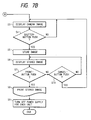
- FIG. 7 A flowchart of the operation in the control unit 16 of the image processing system with the above configuration is shown in Fig. 7.
- a coin insertion signal is sent to the control unit 16 (step S1).
- the control unit 16 which has received the coin insertion signal sends a signal to the power supply unit 15 to start the supply of the electric power to each unit (step S2).
- the control unit 16 receives a status signal as shown in Fig. 8 from the printer 18 at predetermined intervals to determine whether or not the printer 18 is normally operating (step S20). If there is no abnormality such as a shortage or jamming of paper at step S20, the normal control is continued, and the abnormality is checked at predetermined intervals.
- step S3 the image picked up with the video camera 11 is displayed on the monitor 14 (step S3), and if the shutter button 17a is depressed (step S4), a picked up image upon depressing is stored as a still image (step S5). And the stored image is displayed on the monitor 14 (step S6). If the print button 17b of the operation unit 17 is depressed (step S7), the stored image is printed by the video printer 18 (step S8). After the completion of the print, a print termination signal is sent from the video printer 18 to the system control unit 17, and further a signal is sent to the power supply unit 15 to turn off the supply of the power to each unit (step S9). Then the operation is terminated.
- step S7 If the cancel button 17c, rather than the print button 17b, is depressed at step S7, the operation proceeds to step S20 to be placed in a storing wait state, while if the cancel button 17c is not depressed, the operation proceeds to step S6 to be placed in a printing wait state (step S10). If there is any abnormality such as a shortage or jamming of paper at step S20, the inserted coin is repaid (step S21), in which a proper code, a place code and an accident code for the image processing system are sent from the communication unit 31 to the centralized supervisory system (Fig. 3) within the control center (step S22).
- the control unit 41 of the centralized supervisory system which has received the accident contents displays the proper code, the place name and the accident contents for the abnormal image processing system on the monitor 43. And the status content of the image processing system within the storage unit 42 is rewritten into a disenabled state to retrieve the nearest available image processing system. Based on a retrieved result, map data indicating the location of installed image processing system which has been prestored within the storage unit 42 is sent through the communication unit 40 to the image processing system which has caused the accident.
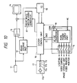
- a schematic circuit configuration of the communication unit 31 is shown in Fig. 9.
- 55 is an accident informing control signal, in which if this signal is turned on, the CPU 53 turns on a line connection control signal 54 to instruct a network control unit (NCU) 50 to connect the line.
- NCU network control unit
- the CPU 53 reads a telephone number of the control center prewritten in a nonvolatile memory such as EEPROM 56, and instructs a DTMF generator 54 to output a DTMF (dual tone multi frequency) code corresponding to its number in sequence by the number in accordance with the specification of the line.
- the centralized supervisory system automatically responds thereto so that a sinusoidal wave signal of 1KHz is sent to the transmission side.
- a band pass filter (BPF) 58 of the communication unit 31 extracts the sinusoidal wave of 1KHz, and an A/D converter 59 converts the detected level into the digital form.
- the CPU 53 judges that the line is connected to the control center if the digital value is equal to or more than a predetermined value, so that the proper code, the place code of installation, and the code of accident contents for the image processing system are read out in sequence from the EEPROM 56, and the DTMF code is sent along with an error correction code added at the last. If they are normally received in the control center, the centralized supervisory system generates a sinusoidal wave signal of 1KHz to notify the transmission side of the normal reception. The communication unit 31 turns off the line if the 1KHz signal is received. The centralized supervisory system displays a booth number, an installation place name, and the accident contents on the monitor 43 to be notified to the supervisor.
- the communication unit 16 of the image processing system receives map data of the nearest available image processing system from the centralized supervisory system and stores them into the image storage unit 12 (step S23).
- the map is displayed on the monitor 14 (step S24), and if the print button of the operation unit 17 is depressed (step S25), it is checked whether or not there is any print sheet (step S26), where if there is any print sheet, the received data is printed (step S27).
- the control operation at steps S24 to S27 is continued if the image processing system is abnormal, and upon returning to the normal condition, the operation is reset to perform the control from step S1.
- the system can inform the control center of the abnormality occurring in the image processing system, if any, the periodic round inspection for the image processing system can be dispensed with.
- the maps for other available image processing systems can be displayed, the user can find out the available image processing system without searching about. As the coin is repaid even if any abnormality may occur during the control, there is no loss in spending the money.
- Fig. 10 is a block diagram of an image processing system in another example of the present invention.
- 11 is a pick-up unit consisting of a video camera
- 12 is an image storage unit constituted of a semiconductor memory, for example, capable of reading and writing the object information from the video camera 11, the image storage unit being capable of storing the 640 pixels in the x direction and the 480 pixels in the y direction.
- the read area for the print can be represented by a rectangle formed by S point (XS, YS) and E point (XE, YE) as the diagonal.
- XS, YS, XE, YE represent the addresses in the image storage unit, respectively.
- 13 to 19 are the same as in Fig. 1.
- 17d is a region shift button for shifting the print region in the image.
- XS, YS, XE, YE By depressing the region button, XS, YS, XE, YE as above described will be increased or decreased.
- XS, YS, XE, YE are initialized when the power is turned on.
- XS, XE are incremented by one if the region shift button 17d of the right direction is depressed, while they are decremented by one if the region shift button 17d of the left direction is depressed.
- YS, YE are decremented by one if the region shift button 17d of the upper direction is depressed, while they are incremented by one if the region shift button 17d of the lower direction is depressed.
- 61 is a mark generator for generating a mark indicating the print region, in which along with that mark, the image is displayed on the monitor 14.
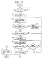
- FIG. 11 A flowchart of the operation in the system control unit 16 of an electronic photo system with the above configuration is shown in Fig. 11.
- a coin insertion signal is sent to the control unit 16 (step S1).
- the system control unit 16 which has received the coin insertion signal sends a signal to the power supply unit 15 to start the supply of the electric power to each unit (step S2). If the supply of the electric power is started, the switch 13 is changed to the camera side to display a compounded image of an image being currently picked up with the video camera 11 and a mark 62 generated by the mark generator 61 on the monitor 14 (step S30).
- the mark generator receives data (XS, YS, XE, YE) representing the print region from the system control unit 16 as previously described, and generates the mark 62 indicating the region as shown in Fig. 12.
- the position of the mark at the start-up of the power supply can be determined by the initial value which the ROM of the system control unit 16 has stored.
- the photographer shifts the mark 62 to a position of preferred picture composition by operating the region shift button 17d while seeing the monitor 14. If the region shift button 17d is depressed (step S31), the system control unit 16 increments or decrements the position data (XS, YS, XE, YE) in accordance with its direction and amount (step S32).
- step S32 The data changed at step S32 is sent to the mark generator 61 to generate the mark in accordance with its data, and the operation proceeds to step S30, where a compounded image of an image being currently picked up with the video camera 11 and a mark 62 generated by the mark generator 61 is displayed on the monitor 14. If the region shift button 17d is not depressed at step S31, the operation proceeds to the next step. If the shutter button 17a of the operation unit 17 is depressed (step S4), the image being picked up at that time is stored in the image storage unit 12 (step S5). Then the switch 13 is changed to the storage unit side, and the stored image is displayed on the monitor 14 to allow the photographer to confirm the image to be printed (step S6). If the print button 17b of the operation unit 17 is depressed (step S7), the image within the print region is printed (step S8).
- x, y represents the address for reading the image data from the image storage unit 12.
- x is set to XS and y is set to YS (steps S41, S42).
- the image data at the address (x,y) is sent to the video printer 18 and printed (step S43).
- x is incremented by one (step S44), and it is checked whether or not x > XE is true (step S45). If x ⁇ XE at step S45, the operation proceeds to step S43 to increment x. If x > XE, a line feed signal is sent to the video printer 18 (step S46) to increment y by one (step S47).
- step S48 it is checked whether or not y > YE is true (step S48). If y ⁇ YE at step S48, the operation proceeds to step S41, where x is reset to XS, and the print operation is continued. If y > YE, a print termination signal is sent to the video printer 18 to terminate the print. As a result of the print, the image as shown in Fig. 14 can be obtained.
- a print termination signal is sent from the video printer 18 to the system control unit 17, and further a signal is sent to the power supply unit 15 to turn off the supply of the power to each unit (step S9). Then the operation is terminated. If the cancel button 17c, rather than the print button 17b, is depressed at step S7, the operation proceeds to step S30, where a compounded image of the image from the video camera 11 and the mark 62 is displayed, while if the cancel button 17c is not depressed, the operation proceeds to step S6 to be placed in a printing wait state (step S10).
- the picture composition can be confirmed with a simple configuration in which a fixed mark indicating the print region of respective print size is displayed on the screen of the monitor 14, without using the mark generator 61 and the region movement button 17d, and with the position data of print region fixed.
- a photograph can be taken in a correct attitude in such a way that if the shutter button 17a of the operation unit 17 is depressed in photographing, the image being currently picked up is stored under the control of the system control unit 16 when a predetermined count value is reached by counting up with a counter contained within the system control unit 16.
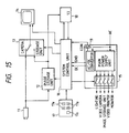
- Fig. 15 is a block diagram of an electronic photo system in one example of the present invention.
- 11 is an image pick-up unit consisting of a video camera
- 12 is an image storage unit constituted of a semiconductor memory, for example, for storing the image information from the video camera 11.
- 13 is a monitor output screen changeover switch
- 14 is a monitor
- 15 is a power supply unit for supplying the power to each unit.
- 16 is a system control unit for controlling the operation of each unit, which is constituted of CPU, RAM, and ROM (not shown).
- the RAM is used as a work area for the CPU, and the ROM has written the contents of control operation or the message data for displaying on the monitor.
- 17 is an operation unit for operating the system control unit 16, comprising a shutter button 17a for starting the storage of image, and a print image select button 17e for specifying a stored image to be printed among four stored images which have been stored in the image storage unit 12.
- 18 is a video printer such as a thermal printer, or a bubble jet printer for discharging the ink by the use of the pressure of bubbles generated by the heat.
- 19 is a detector for detecting the input of a coin.
- FIG. 16 A flowchart of the operation in the system control unit 16 of the electronic photo system having the above configuration is shown in Fig. 16. If the coin detector 19 detects a coin, a coin insertion signal is sent to the system control unit 16 (step S1). The system control unit 16 which has received the coin insertion signal sends a signal to the power supply unit 15 to start the supply of the electric power to each unit (step S2). Next, the switch 13 is changed to the camera side to display an image being currently picked up by the video camera 11 directly on the monitor 14 (step S3).
- step S4 If the shutter button 17a of the operation unit 17 is depressed (step S4), the image being picked up by the video camera 11 is displayed for a predetermined time (steps S50, S51), and the picked up image is stored into the image storage unit 12 (step S52).
- step S52 the switch 13 is changed to the storage unit side to cause the stored image to be displayed on the monitor 14 for a predetermined time, so that the photographer can confirm the image (steps S53, S54).
- the count-up is made every time the system control unit 16 stores the image, in which it is checked whether or not the count-up has been made four times, or four images have been stored (step S55).
- step S55 the counter is below four, the operation proceeds to step S50 to store the image, while if the counter is equal to 4, the monitor is divided into four display sections as shown in Fig. 17 to display collectively four images stored in the image storage unit 12 on the monitor (step S56).
- the photographer selects the image to be printed and then depresses the print image select button 17b of the operation unit 17. If the print image select button 17b is depressed to specify the image to be printed, its specified image is printed (step S57).
- a print termination signal is sent from the video printer 18 to the system control unit 17.
- the system control unit 17 which has received the print termination signal sends a signal to the power supply unit 15 to turn off the supply of the power to each unit (step S9). Then the operation is terminated.
- the image storage unit 12 can store four images in this example, but not limiting to four images, it may be sufficient to store a plurality of images.
- the print image can be specified by depressing the print button while the stored image is being displayed in a repetitive operation of image pick-up, storage and display in series.
- the user can correct for his pose to be more excellent. Furthermore, as a plurality of images are stored and collectively displayed, and the image specified by the user is printed, the user can select a more favorable picture by the comparison between a plurality of images while eliminating the wastes of photographing fee or print sheet.
- Fig. 18 is a block diagram of an image processing system in another example of the present invention.
- 11 is a video camera (for picking up a color image and outputting a color image signal)
- 12 is an image storage unit constituted of a semiconductor memory, for example, for storing the image information from the video camera 11
- 13 is a monitor output screen changeover switch
- 14 is a monitor
- 15 is a power supply unit for supplying the power to each unit.
- 16 is a system control unit for controlling the operation of each unit, which is constituted of CPU, RAM, and ROM (not shown).
- the RAM is used as a work area for the CPU, and the ROM has written the contents of control operation or the message data to be displayed on the monitor.
- 17 is an operation unit for operating the system control unit 16, comprising a shutter button 17a for starting the storage of image, a print button 17b for starting the print of stored image, a cancel button 17c for canceling the stored image to reset the system to a photographing wait state, and a white-and-black/color select button 17f for selecting the white-and-black print or the color print.
- 18 is a video printer such as a thermal printer, or a bubble jet printer for discharging the ink by the use of the pressure of bubbles generated by the heat.
- 19 is a detector for detecting the input of a coin.
- 70 is an image convertor for converting the color image information read out from the image storage unit 12 into the white-and-black image information
- 71 is a print image changeover switch for changing the video printer 18 to print the color or white-and-black image.
- FIG. 19 A flowchart of the operation in the system control unit 16 of an electronic photo system having the above configuration is shown in Fig. 19.
- a coin insertion signal is sent to the system control unit 16 (step S1).
- the system control unit 16 which has received the coin insertion signal sends a signal to the power supply unit 15 which starts the supply of the electric power to each unit (step S2).
- the switch 13 is changed to the camera side to display an image being currently picked up by the video camera 11 directly on the monitor 14 (step S3). If the shutter button 17a of the operation unit 17 is depressed (step S4), the image being picked up at that time is stored as a still image into the image storage unit 12 (step S5).
- the switch 13 is changed to the storage unit side to cause the stored image to be displayed on the monitor 14, so that the photographer can confirm the image to be printed (step S6).
- the print button 17b of the operation unit 17 is depressed, a determination is made whether the instruction is for a white-and-black print or color print (step S60). If the white-and-black is selected with the white-and-black/color select button 17f, the system control unit 16 changes the print image changeover switch 71 to the side of the image converter 70, which converts the color image information from the image storage unit 12 into the white-and-black image information which is then output to the video printer 18 (step S61).
- the system control unit 16 changes the print image changeover switch 71 to the opposite side of the image converter 70, so that the image storage unit 12 and the video printer 18 are directly connected, whereby the color image information from the image storage unit 12 is directly output to the video printer 18 (step S62). Based on the image information sent therein, the color or white-and-black image is printed with the video printer 18 (step S8).
- a print termination signal is sent from the video printer 18 to the system control unit 17, and further a signal is sent to the power supply unit 15 to turn off the supply of the power to each unit (step S9). Then the operation is terminated. If the cancel button 17c, rather than the print button 17b, is depressed at step S7, the operation proceeds to step S3 to be placed in a storing wait state, while if the cancel button 17c is not depressed, the operation proceeds to step S6 to be placed in a printing wait state (step S10).
- Fig. 20 is a block diagram of an improved system of Fig. 18.
- a different point from Fig. 18 is that the image converter 70 and the print image changeover switch 71 are connected at the front stage of the switch 13.
- the white-and-black image is displayed on the monitor 14, while if the color is selected, the color image is displayed on the monitor 14.
- both the color and white-and-black images can be printed to allow the user to obtain a picture in accordance with his desire. Further, the white-and-black or color image to be printed can be confirmed on the monitor.
- Fig. 21 is a block diagram of an image processing system in another example of the present invention.
- 11 is a monochrome video camera which issues a synchronizing signal in synchronism with the read out of an image.
- 12 to 19 are the same as in Fig. 1.
- 75 is a rotation filter
- 76 is a motor control unit
- 77 is a stepping motor.
- Fig. 22 shows a profile of the rotation filter.
- R, G and B are windows having red, green and blue transmission filters mounted, respectively, and T is an achromatic transparent window.
- the video camera 11 picks up an image through those windows.
- the system control unit 16 outputs a signal indicating its selection to the motor control unit 76, which controls the driving of the motor 77 so that the T window of the rotation filter 75 is positioned in front of the video camera 11, in which the image is picked up through the T window with the rotation filter held in its state (steps S71, S72).
- the system control unit 16 outputs a signal indicating its selection to the motor control unit 76.
- the motor control unit 76 controls the driving of the motor 77 in synchronism with the synchronizing signal output from the video camera 11, so that R, G and B windows of the rotation filter are positioned in front of the video camera 11 in sequence.
- the image passing through the R, G and B filters from the video camera 11 is read out in sequence (steps S73, S74, S75), in which the system control unit 16 operates on the color image information by composing the color images passing through respective filters to obtain a color image.
- the white-and-black and color image can be printed to provide a picture in accordance with a desire of the user.
- a low cost image processing system can be implemented.
- Fig. 25 is a block diagram showing another example of the present invention.
- 11 is an image pick-up unit consisting of a video camera
- 80 is an external video input terminal
- 81 is a video input select changeover switch
- 82 is an external input terminal connection detector unit
- 12 is an image storage unit constituted of a semiconductor memory, for example, for storing the information of an object from the video camera 11
- 13 is a monitor output screen changeover switch
- 14 is a monitor
- 15 is a power supply unit for supplying the electric power to each unit
- 16 is a system control unit for controlling the operation of each unit
- 17 is an operation unit for operating the system control unit
- 18 is a video printer which is a print output unit
- 19 is a detector for detecting the input of a coin.
- FIG. 25 A flowchart of the operation in the system control unit 16 of an electronic photo system having the above configuration is shown in Fig. 25.
- the coin detector 19 detects a coin
- a coin insertion signal is sent to the system control unit 16 (step S1).
- the system control unit 16 which has received the coin insertion signal sends a signal to the power supply unit 15 to start the supply of the electric power to each unit (step S2).
- the external terminal connection detector unit 22 detects whether or not the video input is connected to the external video input terminal. If the external terminal is connected (step S81), the video input select changeover switch 81 is changed to the side of the external video input terminal 80 to input an image signal from the external video input terminal 80 (step S82).
- step S81 If the external terminal is not connected at step S81, the video input select changeover switch 81 is changed to the side of the video camera 11 to input an image signal from the video camera 11 (step S83). And the input image selected at steps S81 to S83 is displayed (step S3). If the shutter button 17a of the operation unit 17 is depressed (step S4), the image being picked up at that time is stored as a still image into the image storage unit 12 (step S5).
- step S6 the switch 13 is changed to the storage unit side to cause the stored image to be displayed on the monitor 14 so that the photographer can confirm the image to be printed (step S6). If the print button 17b of the operation unit 17 is depressed (step S7), the stored image is printed by the video printer 18 (step S8). After the completion of the print, a print termination signal is sent from the video printer 18 to the system control unit 17, and further a signal is sent to the power supply unit 15 to turn off the supply of the power to each unit (step S9). Then the operation is terminated.
- step S7 If the cancel button 17c, rather than the print button 17b, is depressed at step S7, the operation proceeds to step S3 to be placed in a storing wait state, while if the cancel button 17c is not depressed, the operation proceeds to step S6 to be placed in a printing wait state (step S10).
- the system control unit 16 can control the video input select switch 81 to be changed to the side of the external video input terminal 80 upon receiving the detection signal from the synchronizing signal detector 83.
- the image recorded on a video tape can be printed by providing a video tape deck, instead of the external video input terminal 80.
- Fig. 27 is a block diagram of an image processing system in another example of the present invention. 11 to 19 are the same as in Fig. 1.
- 85 is a decision circuit for deciding whether or not the image stored in the image storage unit 12 is blurred
- 86 is a character generating circuit for generating the character for use in displaying a message on the monitor 14
- 87 is a signal amplifier for amplifying a voice signal for the message output from the system control unit 16
- 88 is a speaker for outputting the voice signal amplified by the signal amplifier as the voice.
- the system control unit 16 performs the control so that if the shutter button 17a is depressed, the image from the video camera 11 at the times t1, t2 are stored in a first field A and a second field B of the image storage unit 12, respectively.
- the image stored in the second field memory is equal to an image to which the object of the image stored in the first field memory has moved right upward, as shown in Fig. 28.
- the image stored in the image storage unit 12 is directly output to the monitor 14, a blurred image is displayed as shown in Fig. 29. If the image stored in the image storage unit 12 is output to the printer 18, the blurred image is also printed as shown in Fig. 30.
- the value representing the correlation between the block of interest A and the block of interest B can be obtained from the values of pixel Ai within a block of interest A in the first field A and the values of pixel Bi within a block of interest B in the second field B, by using the following expression (see Japanese Patent Publication Gazette No. 2-52914).
- C ⁇ 1 m
- the correlation value C between the block of interest A, and the block of interest B at the position corresponding to the block of interest A with the eight blocks around the block of interest B can be obtained for each block, in which the position of the block having the least correlation value C is stored, and it is decided that the blurring occurred in photographing if the correlation value C between the blocks other than the block of interest among the nine blocks in the second field and the block of interest A is least, whereby a blurring detection signal is output to the system control unit 16. Also, when the correlation value C between the block of interest B and the block of interest A is least, the correlation value C and a preset constant value C B are compared, in which if C > C B , the blurring detection signal is output to the system control unit 16.
- the operation of detecting the blurring by obtaining the correlation value C between the block of interest A and each block among the nine blocks in the second field is performed for all blocks in the first field by changing the block of interest A from A(0,0) block to A(1,k) block.
- the unwasteful printing is enabled by aligning the print range with an integral multiple of the operation block for the movement vector.
- a flowchart of the operation in the system control unit 16 of an electronic photo system with the above configuration is shown in Figs. 33 and 34.
- the steps S1 to S7 and S10 are the same as in Fig. 3.
- the blurring detector 85 detects the blurring of stored image and the system control unit 16 receives a blurring detection signal from the blurring detector 85, a message such as "Blurring" from the character generating circuit 86 is output to the monitor 14 to inform the user of the blurring.
- the chime sound or the voice such as "Blurring” is output via the signal amplifier 87 from the speaker 88 (step S87).
- the print button 17b is depressed (step S88)
- the stored image is printed by the video printer 18 (step S8).
- a print termination signal is sent from the video printer 18 to the system control unit 17, and further a signal is sent to the power supply unit 15 to turn off the supply of the power to each unit (step S9). Then the operation is terminated.
- step S88 if the print button 17b is not depressed, the operation proceeds to step S3, where a further photograph is taken again without printing of the blurred image.
- step S86 if there is no blurring, the operation proceeds to step S8, where the normal print operation is performed.
- This example is one of correcting for the blurring of stored image, if any, by further developing the method of detecting the movement vector as shown in Figs. 31 and 32.
- the movement vector for each block is as shown in Fig. 35 so that the blurred block can be detected.
- the blurring detector 85 writes the image information of block having the blurring dsetected in the first field to the position corresponding to the block of the first field in the second field, as shown in Figs. 36 and 37 (in the figure, 1 indicates the first field image, and 2 indicates the second field image).
- the image in the first field remains unchanged and the image in the second field is the first field image for blurred image or the second field image for unblurred block, as shown in Fig. 38, so that the image without blurring can be printed.
- the blurring can be corrected, and the picture without blurring can be obtained.
Abstract
Description
- The present invention relates to an image processing system for photographing an object and printing a photographed image.
- Conventionally, photo booth apparatuses have been provided for automatically taking a picture for the identification card or passport with the input of a coin, in which the apparatus comprises a camera, a photo developing unit and a flash with the optical silver salt photography.
- However, with such apparatuses, due to pollution problems resulting from the use of chemicals to develop the photo, some limitations were imposed on the installing location, or great labors were taken for the maintenance of apparatus.
- Also, it took some time to perform the chemical processing for development, so that the user had to wait for a picture to be completed for about five minutes, after the picture was taken.
- Furthermore, there was a drawback that a photographed result was not seen until it was developed, and if the photographing might fail, the sheet was wasted or the fee was charged irrespective of the failure because the picture had been already printed on the sheet.
- Also, it was impossible to take a plurality of photographs and print only the best photographed picture among them.
- Furthermore, there was a drawback that when supplies were used up or the apparatus might fail, the service was only inhibited, and an abnormal condition of the apparatus could be first detected by a service man in the round inspection, so that the user could not use the apparatus for a long term, which was inconvenient for the user and unprofitable for the dealer.
- Also, since the black-and-white apparatus and the color apparatus were separately provided, it was necessary to search about for an apparatus which allows a desired picture to be taken.
- Furthermore, there was a drawback that if various functions were installed, the cost would be raised.
- Furthermore, it was impossible to print images other than those photographed with the same apparatus.
- The present invention was achieved in view of the above-mentioned respects, and its object is to provide an improved image processing apparatus.
- Further, it is an object of the present invention to provide an image processing system without anxieties of the pollution.
- Further, it is an object of the present invention to provide an image processing system with a simple construction and of an easy maintenance.
- Further, it is an object of the present invention to provide an image processing system which is always available to the user, and capable of rapid processing.
- Further, it is an object of the present invention to provide an image processing apparatus which allows a photographed result desired by the user to be printed.
- Further, it is an object of the present invention to provide an image processing apparatus which allows a failure of the apparatus to be detected at early time.
- Further, it is an object of the present invention to provide an image processing system capable of printing both the color and black-and-white pictures.
- Further, it is an object of the present invention to provide an image processing system which allows various functions to be implemented at low cost.
- Further, it is an object of the present invention to provide an image processing system which allows various images to be printed.
- Other objects and features of the present invention will be apparent from the following description and the drawings.
- Fig. 1 is a block diagram of an image processing system in an example of the present invention.
- Fig. 2 is an external view of the image processing system in the example.
- Fig. 3 is a flowchart of the operation in a
system control unit 16 as shown in Fig. 1. - Fig. 4 is a flowchart of another operation in the
system control unit 16 as shown in Fig. 1. - Fig. 5 is a block diagram of an image processing system in another example.
- Fig. 6 is a block diagram of a centralized supervisory system for making the centralized supervision of a plurality of image processing system.
- Fig. 7 is a flowchart of the operation in a
system control unit 16 as shown in Fig. 5. - Fig. 8 is a table showing the signals indicating the states of a
printer 18 as shown in Fig. 5. - Fig. 9 is a specific circuit diagram of a
communication unit 31 as shown in Fig. 5. - Fig. 10 is a block diagram of an image processing system in another example.
- Fig. 11 is a flowchart of the operation in a
system control unit 16 as shown in Fig. 10. - Fig. 12 is a view showing a mark indicating a print region displayed on a
monitor 14. - Fig. 13 is a flowchart of the printing as shown in Fig. 10.
- Fig. 14 is a view showing a result printed with a region specification as shown in Fig. 12.
- Fig. 15 is a block diagram of an image processing system in another example.
- Fig. 16 is a flowchart of the operation in a
system control unit 16 as shown in Fig. 15. - Fig. 17 is a view showing a display screen on a
monitor 14. - Fig. 18 is a block diagram of an image processing system in another example.
- Fig. 19 is a flowchart of the operation in a
system control unit 16 as shown in Fig. 18. - Fig. 20 is a block diagram of an image processing system in another example.
- Fig. 21 is a block diagram of an image processing system in another example.
- Fig. 22 is a configuration view of a
rotation filter 75 as shown in Fig. 21. - Fig. 23 is a flowchart of the image pick-up as shown in Fig. 21.
- Fig. 24 is a block diagram of an image processing system in another example.
- Fig. 25 is a flowchart of the operation in a
system control unit 16 as shown in Fig. 24. - Fig. 26 is a block diagram of an image processing system in another embodiment.
- Fig. 27 is a block diagram of an image processing system in another embodiment.
- Fig. 28 is a view showing the movement of an image in the time direction.
- Fig. 29 is a view showing a blurred image displayed on the
monitor 14. - Fig. 30 is a view showing the blurred image printed by a
printer 18. - Fig. 31 is a view showing the image stored in a first field of
image storage unit 12. - Fig. 32 is a view showing the image stored in a second field of
image storage unit 12. - Fig. 33 is a flowchart of the operation in a
system control unit 16 as shown in Fig. 27. - Fig. 34 is a flowchart of the operation in the
system control unit 16 as shown in Fig. 27. - Fig. 35 is a view showing detected movement vectors.
- Fig. 36 is a view showing the image in the first field after the correction for the blurring.
- Fig. 37 is a view showing the image in the second field after correction for the blurring.
- Fig. 38 is a view showing a printed image image after the correction for the blurring.
- The preferred embodiments will be described below in detail with reference to the drawings.
- Fig. 1 is a block diagram of an image processing system in one example of the present invention. 11 is an image pick-up unit consisting of a video camera, 12 is an image storage unit constituted of a semiconductor memory, for example, for storing the image information from the
video camera shutter button 17a for starting the storage of image, aprint button 17b for starting the print of stored image, and a cancelbutton 17c for cancelling the stored image to reset the system to a photographing wait state. 18 is a video printer such as a thermal printer, or a bubble jet printer for discharging the ink by the use of the pressure of bubbles generated by the heat. 19 is a detector for detecting the input of a coin. - Fig. 2 is an external view of this example. 20 is a lighting for lighting an object, such as a fluorescent lamp. 21 is a coin slot.
- A flowchart of the operation in the
system control unit 16 of an electronic photo system having the above configuration is shown in Fig. 3. If thecoin detector 19 detects a coin, a coin insertion signal is sent to the system control unit 16 (step S1). Thesystem control unit 16 which has received the coin insertion signal sends a signal to thepower supply unit 15 to start the supply of the electric power to each unit (step S2). Next, theswitch 13 is changed to the camera side to display an image being currently picked up directly on the monitor 14 (step S3). If theshutter button 17a of theoperation unit 17 is depressed (step S4.), the image being picked up at that time is stored as a still image into the image storage unit 12 (step S5). - Next, the
switch 13 is changed to the storage unit side to display the stored image on themonitor 14, so that the user can confirm the image to be printed (step S6). If theprint button 17b of theoperation unit 17 is depressed (step S7), the stored image is printed with the video printer 18 (step S8). After the completion of the print, a print termination signal is sent from thevideo printer 18 to thesystem control unit 17, and further a signal is sent to thepower supply unit 15 to turn off the supply of the power to each unit (step S9). Then the operation is terminated. At step S7, if the cancelbutton 17c, rather than theprint button 17b, is depressed, the operation proceeds to step S10 to be placed in a storing wait state, while if the cancelbutton 17c is not depressed, the operation proceeds to step S6 to be placed in a printing wait state (step S10). - It will be appreciated that a photograph can be taken in a correct attitude in such a way that if the
shutter button 17a of the operation unti 17 is depressed in photographing, an image being currently picked up is stored under the control of thesystem control unit 16 when a predetermined count value is reached by counting up with a counter contained within thesystem control unit 16. - It will be also appreciated that a photograph can be taken in a correct attitude in such a way that the
shutter button 17a of theoperation unit 17 is disposed at the foot of the photographer to depress theshutter button 17a with his foot. Further, the flash photography can be implemented by the use of a flash lamp as thelighting 20. - Thereby, it is possible to obtain a more favorable picture because of the effective measures against the pollution, the easy maintenance, a shortened time for the completion of a picture, and the savings of print cost and print sheets.
- Another example will be described below.
- Fig. 4 is a flowchart showing the operation of an image processing system in another example of the present invention. The block diagram of this example is the same as in Fig. 1. This example allows the same picture to be printed on plural sheets. The steps S1 to S10 are the same as in Fig. 3, and the explanation will be omitted. After the stored image has been printed at step S8, a timer within the
system control unit 16 is turned on (step S11), and a message notifying whether or not the currently stored image should be further printed (e.g., "Insert a coin if one more sheet is printed") is displayed on the monitor 14 (step S12). If the coin is detected, the operation proceeds to step S6 to be placed in a printing wait state (step S13). If the coin is not detected at step S13, it is examined whether or not a predetermined time has passed with the timer of the system control unit 16 (step S14). If the predetermined time has not passed at step S14, the operation proceeds to step S12 to wait for the input of a coin, while if the predetermined time has passed, a signal is sent from thesystem control unit 17 to thepower supply unit 15 to turn off the power supply for each unit (step S15). Then the operation is terminated. - If the inserted coin is detected at step S13, the stored image is displayed on the monitor 14 (step S6), and the operation is placed in a wait state for a print instruction signal of stored image (step S7).
- With this configuration, it is possible to print a plurality of pictures for a favorable image which has been once stored.
- It will be appreciated that a plurality of pictures for a favorable image can be obtained in such a way that if the
print button 17b of theoperation unit 17 is depressed after photographing, the system control unit 16a makes the control so that a predetermined number of sheets are printed. - Next, another example of the present invention will be described.
- Fig. 5 is a block diagram of an image processing system showing another example of the present invention. 11 to 19 are the same as in Fig. 1.
- 30 is a sheet-fed unit, 31 is a communication unit for communicating with a control center via a telephone line when the accident occurs, and 32 is the telephone line.
- Fig. 6 is a block diagram of a centralized supervisory system which makes the centralized supervision over a plurality of image processing systems. 40 is a communication unit for communicating with a plurality of image processing systems via the
telephone line control unit 41. - A flowchart of the operation in the
control unit 16 of the image processing system with the above configuration is shown in Fig. 7. If thecoin detector 19 detects a coin, a coin insertion signal is sent to the control unit 16 (step S1). Thecontrol unit 16 which has received the coin insertion signal sends a signal to thepower supply unit 15 to start the supply of the electric power to each unit (step S2). Thecontrol unit 16 receives a status signal as shown in Fig. 8 from theprinter 18 at predetermined intervals to determine whether or not theprinter 18 is normally operating (step S20). If there is no abnormality such as a shortage or jamming of paper at step S20, the normal control is continued, and the abnormality is checked at predetermined intervals. At the normal condition, the image picked up with thevideo camera 11 is displayed on the monitor 14 (step S3), and if theshutter button 17a is depressed (step S4), a picked up image upon depressing is stored as a still image (step S5). And the stored image is displayed on the monitor 14 (step S6). If theprint button 17b of theoperation unit 17 is depressed (step S7), the stored image is printed by the video printer 18 (step S8). After the completion of the print, a print termination signal is sent from thevideo printer 18 to thesystem control unit 17, and further a signal is sent to thepower supply unit 15 to turn off the supply of the power to each unit (step S9). Then the operation is terminated. If the cancelbutton 17c, rather than theprint button 17b, is depressed at step S7, the operation proceeds to step S20 to be placed in a storing wait state, while if the cancelbutton 17c is not depressed, the operation proceeds to step S6 to be placed in a printing wait state (step S10). If there is any abnormality such as a shortage or jamming of paper at step S20, the inserted coin is repaid (step S21), in which a proper code, a place code and an accident code for the image processing system are sent from thecommunication unit 31 to the centralized supervisory system (Fig. 3) within the control center (step S22). - The
control unit 41 of the centralized supervisory system, which has received the accident contents displays the proper code, the place name and the accident contents for the abnormal image processing system on themonitor 43. And the status content of the image processing system within thestorage unit 42 is rewritten into a disenabled state to retrieve the nearest available image processing system. Based on a retrieved result, map data indicating the location of installed image processing system which has been prestored within thestorage unit 42 is sent through thecommunication unit 40 to the image processing system which has caused the accident. - A schematic circuit configuration of the
communication unit 31 is shown in Fig. 9. 55 is an accident informing control signal, in which if this signal is turned on, theCPU 53 turns on a lineconnection control signal 54 to instruct a network control unit (NCU) 50 to connect the line. Next, theCPU 53 reads a telephone number of the control center prewritten in a nonvolatile memory such asEEPROM 56, and instructs aDTMF generator 54 to output a DTMF (dual tone multi frequency) code corresponding to its number in sequence by the number in accordance with the specification of the line. If the line is connected to the control center, the centralized supervisory system automatically responds thereto so that a sinusoidal wave signal of 1KHz is sent to the transmission side. A band pass filter (BPF) 58 of thecommunication unit 31 extracts the sinusoidal wave of 1KHz, and an A/D converter 59 converts the detected level into the digital form. TheCPU 53 judges that the line is connected to the control center if the digital value is equal to or more than a predetermined value, so that the proper code, the place code of installation, and the code of accident contents for the image processing system are read out in sequence from theEEPROM 56, and the DTMF code is sent along with an error correction code added at the last. If they are normally received in the control center, the centralized supervisory system generates a sinusoidal wave signal of 1KHz to notify the transmission side of the normal reception. Thecommunication unit 31 turns off the line if the 1KHz signal is received. The centralized supervisory system displays a booth number, an installation place name, and the accident contents on themonitor 43 to be notified to the supervisor. - The
communication unit 16 of the image processing system receives map data of the nearest available image processing system from the centralized supervisory system and stores them into the image storage unit 12 (step S23). The map is displayed on the monitor 14 (step S24), and if the print button of theoperation unit 17 is depressed (step S25), it is checked whether or not there is any print sheet (step S26), where if there is any print sheet, the received data is printed (step S27). The control operation at steps S24 to S27 is continued if the image processing system is abnormal, and upon returning to the normal condition, the operation is reset to perform the control from step S1. - Note that the available image processing systems can be output with the expression of words.
- In this way, as the system can inform the control center of the abnormality occurring in the image processing system, if any, the periodic round inspection for the image processing system can be dispensed with. As the maps for other available image processing systems can be displayed, the user can find out the available image processing system without searching about. As the coin is repaid even if any abnormality may occur during the control, there is no loss in spending the money.
- Next, another example will be described.
- Fig. 10 is a block diagram of an image processing system in another example of the present invention. 11 is a pick-up unit consisting of a video camera, 12 is an image storage unit constituted of a semiconductor memory, for example, capable of reading and writing the object information from the
video camera 11, the image storage unit being capable of storing the 640 pixels in the x direction and the 480 pixels in the y direction. The read area for the print can be represented by a rectangle formed by S point (XS, YS) and E point (XE, YE) as the diagonal. XS, YS, XE, YE represent the addresses in the image storage unit, respectively. 13 to 19 are the same as in Fig. 1. 17d is a region shift button for shifting the print region in the image. By depressing the region button, XS, YS, XE, YE as above described will be increased or decreased. XS, YS, XE, YE are initialized when the power is turned on. XS, XE are incremented by one if theregion shift button 17d of the right direction is depressed, while they are decremented by one if theregion shift button 17d of the left direction is depressed. YS, YE are decremented by one if theregion shift button 17d of the upper direction is depressed, while they are incremented by one if theregion shift button 17d of the lower direction is depressed. - 61 is a mark generator for generating a mark indicating the print region, in which along with that mark, the image is displayed on the
monitor 14. - A flowchart of the operation in the
system control unit 16 of an electronic photo system with the above configuration is shown in Fig. 11. If thecoin detector 19 detects a coin, a coin insertion signal is sent to the control unit 16 (step S1). Thesystem control unit 16 which has received the coin insertion signal sends a signal to thepower supply unit 15 to start the supply of the electric power to each unit (step S2). If the supply of the electric power is started, theswitch 13 is changed to the camera side to display a compounded image of an image being currently picked up with thevideo camera 11 and amark 62 generated by themark generator 61 on the monitor 14 (step S30). At this time, the mark generator receives data (XS, YS, XE, YE) representing the print region from thesystem control unit 16 as previously described, and generates themark 62 indicating the region as shown in Fig. 12. The position of the mark at the start-up of the power supply can be determined by the initial value which the ROM of thesystem control unit 16 has stored. The photographer shifts themark 62 to a position of preferred picture composition by operating theregion shift button 17d while seeing themonitor 14. If theregion shift button 17d is depressed (step S31), thesystem control unit 16 increments or decrements the position data (XS, YS, XE, YE) in accordance with its direction and amount (step S32). The data changed at step S32 is sent to themark generator 61 to generate the mark in accordance with its data, and the operation proceeds to step S30, where a compounded image of an image being currently picked up with thevideo camera 11 and amark 62 generated by themark generator 61 is displayed on themonitor 14. If theregion shift button 17d is not depressed at step S31, the operation proceeds to the next step. If theshutter button 17a of theoperation unit 17 is depressed (step S4), the image being picked up at that time is stored in the image storage unit 12 (step S5). Then theswitch 13 is changed to the storage unit side, and the stored image is displayed on themonitor 14 to allow the photographer to confirm the image to be printed (step S6). If theprint button 17b of theoperation unit 17 is depressed (step S7), the image within the print region is printed (step S8). - The print at step S8 will be described in detail with reference to Fig. 13. x, y represents the address for reading the image data from the
image storage unit 12. To begin with, x is set to XS and y is set to YS (steps S41, S42). Next, the image data at the address (x,y) is sent to thevideo printer 18 and printed (step S43). And x is incremented by one (step S44), and it is checked whether or not x > XE is true (step S45). If x ≦ XE at step S45, the operation proceeds to step S43 to increment x. If x > XE, a line feed signal is sent to the video printer 18 (step S46) to increment y by one (step S47). And it is checked whether or not y > YE is true (step S48). If y ≦ YE at step S48, the operation proceeds to step S41, where x is reset to XS, and the print operation is continued. If y > YE, a print termination signal is sent to thevideo printer 18 to terminate the print. As a result of the print, the image as shown in Fig. 14 can be obtained. - After the completion of the print, a print termination signal is sent from the
video printer 18 to thesystem control unit 17, and further a signal is sent to thepower supply unit 15 to turn off the supply of the power to each unit (step S9). Then the operation is terminated. If the cancelbutton 17c, rather than theprint button 17b, is depressed at step S7, the operation proceeds to step S30, where a compounded image of the image from thevideo camera 11 and themark 62 is displayed, while if the cancelbutton 17c is not depressed, the operation proceeds to step S6 to be placed in a printing wait state (step S10). - It should be noted that the picture composition can be confirmed with a simple configuration in which a fixed mark indicating the print region of respective print size is displayed on the screen of the
monitor 14, without using themark generator 61 and theregion movement button 17d, and with the position data of print region fixed. - It will be appreciated that a photograph can be taken in a correct attitude in such a way that if the
shutter button 17a of theoperation unit 17 is depressed in photographing, the image being currently picked up is stored under the control of thesystem control unit 16 when a predetermined count value is reached by counting up with a counter contained within thesystem control unit 16. - It is also possible to change the print size by inputting the size data in addition to the position data of the print region.
- In this way, as the user can confirm the photographed result before the picture is printed, a more favorable picture can be obtained while eliminating the wastes of photographing fee or print sheet. Furthermore, as a movable print region mark is displayed on the monitor, the composition of picture can be confirmed so as to be changed without moving the picture.
- Next, another example of the present invention will be described.
- Fig. 15 is a block diagram of an electronic photo system in one example of the present invention. 11 is an image pick-up unit consisting of a video camera, and 12 is an image storage unit constituted of a semiconductor memory, for example, for storing the image information from the
video camera 11. 13 is a monitor output screen changeover switch, 14 is a monitor, and 15 is a power supply unit for supplying the power to each unit. 16 is a system control unit for controlling the operation of each unit, which is constituted of CPU, RAM, and ROM (not shown). The RAM is used as a work area for the CPU, and the ROM has written the contents of control operation or the message data for displaying on the monitor. 17 is an operation unit for operating thesystem control unit 16, comprising ashutter button 17a for starting the storage of image, and a print imageselect button 17e for specifying a stored image to be printed among four stored images which have been stored in theimage storage unit 12. 18 is a video printer such as a thermal printer, or a bubble jet printer for discharging the ink by the use of the pressure of bubbles generated by the heat. 19 is a detector for detecting the input of a coin. - A flowchart of the operation in the
system control unit 16 of the electronic photo system having the above configuration is shown in Fig. 16. If thecoin detector 19 detects a coin, a coin insertion signal is sent to the system control unit 16 (step S1). Thesystem control unit 16 which has received the coin insertion signal sends a signal to thepower supply unit 15 to start the supply of the electric power to each unit (step S2). Next, theswitch 13 is changed to the camera side to display an image being currently picked up by thevideo camera 11 directly on the monitor 14 (step S3). If theshutter button 17a of theoperation unit 17 is depressed (step S4), the image being picked up by thevideo camera 11 is displayed for a predetermined time (steps S50, S51), and the picked up image is stored into the image storage unit 12 (step S52). Next, theswitch 13 is changed to the storage unit side to cause the stored image to be displayed on themonitor 14 for a predetermined time, so that the photographer can confirm the image (steps S53, S54). The count-up is made every time thesystem control unit 16 stores the image, in which it is checked whether or not the count-up has been made four times, or four images have been stored (step S55). At step S55, the counter is below four, the operation proceeds to step S50 to store the image, while if the counter is equal to 4, the monitor is divided into four display sections as shown in Fig. 17 to display collectively four images stored in theimage storage unit 12 on the monitor (step S56). By seeing a collectively displayed monitor screen, the photographer selects the image to be printed and then depresses the print imageselect button 17b of theoperation unit 17. If the print imageselect button 17b is depressed to specify the image to be printed, its specified image is printed (step S57). After the completion of the print, a print termination signal is sent from thevideo printer 18 to thesystem control unit 17. Thesystem control unit 17 which has received the print termination signal sends a signal to thepower supply unit 15 to turn off the supply of the power to each unit (step S9). Then the operation is terminated. - The
image storage unit 12 can store four images in this example, but not limiting to four images, it may be sufficient to store a plurality of images. - It will be appreciated that the print image can be specified by depressing the print button while the stored image is being displayed in a repetitive operation of image pick-up, storage and display in series.
- In this way, by storing a picked-up image of the camera and displaying the stored image in succession, the user can correct for his pose to be more excellent. Furthermore, as a plurality of images are stored and collectively displayed, and the image specified by the user is printed, the user can select a more favorable picture by the comparison between a plurality of images while eliminating the wastes of photographing fee or print sheet.
- Next, another example of the present invention will be described below.
- Fig. 18 is a block diagram of an image processing system in another example of the present invention. 11 is a video camera (for picking up a color image and outputting a color image signal), 12 is an image storage unit constituted of a semiconductor memory, for example, for storing the image information from the
video camera system control unit 16, comprising ashutter button 17a for starting the storage of image, aprint button 17b for starting the print of stored image, a cancelbutton 17c for canceling the stored image to reset the system to a photographing wait state, and a white-and-black/color select button 17f for selecting the white-and-black print or the color print. 18 is a video printer such as a thermal printer, or a bubble jet printer for discharging the ink by the use of the pressure of bubbles generated by the heat. 19 is a detector for detecting the input of a coin. - 70 is an image convertor for converting the color image information read out from the
image storage unit 12 into the white-and-black image information, and 71 is a print image changeover switch for changing thevideo printer 18 to print the color or white-and-black image. - A flowchart of the operation in the
system control unit 16 of an electronic photo system having the above configuration is shown in Fig. 19. If thecoin detector 19 detects a coin, a coin insertion signal is sent to the system control unit 16 (step S1). Thesystem control unit 16 which has received the coin insertion signal sends a signal to thepower supply unit 15 which starts the supply of the electric power to each unit (step S2). Next, theswitch 13 is changed to the camera side to display an image being currently picked up by thevideo camera 11 directly on the monitor 14 (step S3). If theshutter button 17a of theoperation unit 17 is depressed (step S4), the image being picked up at that time is stored as a still image into the image storage unit 12 (step S5). - Next, the
switch 13 is changed to the storage unit side to cause the stored image to be displayed on themonitor 14, so that the photographer can confirm the image to be printed (step S6). If theprint button 17b of theoperation unit 17 is depressed, a determination is made whether the instruction is for a white-and-black print or color print (step S60). If the white-and-black is selected with the white-and-black/color select button 17f, thesystem control unit 16 changes the printimage changeover switch 71 to the side of theimage converter 70, which converts the color image information from theimage storage unit 12 into the white-and-black image information which is then output to the video printer 18 (step S61). If the color is selected with the white-and-black/color select button 17f at step S60, thesystem control unit 16 changes the printimage changeover switch 71 to the opposite side of theimage converter 70, so that theimage storage unit 12 and thevideo printer 18 are directly connected, whereby the color image information from theimage storage unit 12 is directly output to the video printer 18 (step S62). Based on the image information sent therein, the color or white-and-black image is printed with the video printer 18 (step S8). - After the completion of the print, a print termination signal is sent from the
video printer 18 to thesystem control unit 17, and further a signal is sent to thepower supply unit 15 to turn off the supply of the power to each unit (step S9). Then the operation is terminated. If the cancelbutton 17c, rather than theprint button 17b, is depressed at step S7, the operation proceeds to step S3 to be placed in a storing wait state, while if the cancelbutton 17c is not depressed, the operation proceeds to step S6 to be placed in a printing wait state (step S10). - Fig. 20 is a block diagram of an improved system of Fig. 18. A different point from Fig. 18 is that the
image converter 70 and the printimage changeover switch 71 are connected at the front stage of theswitch 13. Thus, if the white-and-black is selected with the white-and-black/color select button 17f, the white-and-black image is displayed on themonitor 14, while if the color is selected, the color image is displayed on themonitor 14. Hence, both the color and white-and-black images can be printed to allow the user to obtain a picture in accordance with his desire. Further, the white-and-black or color image to be printed can be confirmed on the monitor. - Next, another example of the present invention will be described below.
- Fig. 21 is a block diagram of an image processing system in another example of the present invention. 11 is a monochrome video camera which issues a synchronizing signal in synchronism with the read out of an image. 12 to 19 are the same as in Fig. 1. 75 is a rotation filter, 76 is a motor control unit, and 77 is a stepping motor. Fig. 22 shows a profile of the rotation filter.
- R, G and B are windows having red, green and blue transmission filters mounted, respectively, and T is an achromatic transparent window. The
video camera 11 picks up an image through those windows. - With such a configuration, if the white-and-black is selected with the white-and-black/color select button on the
operation unit 17, thesystem control unit 16 outputs a signal indicating its selection to themotor control unit 76, which controls the driving of themotor 77 so that the T window of therotation filter 75 is positioned in front of thevideo camera 11, in which the image is picked up through the T window with the rotation filter held in its state (steps S71, S72). On the other hand, if the color is selected with the white-and-color select button on theoperation unit 17, thesystem control unit 16 outputs a signal indicating its selection to themotor control unit 76. Themotor control unit 76 controls the driving of themotor 77 in synchronism with the synchronizing signal output from thevideo camera 11, so that R, G and B windows of the rotation filter are positioned in front of thevideo camera 11 in sequence. As a result, the image passing through the R, G and B filters from thevideo camera 11 is read out in sequence (steps S73, S74, S75), in which thesystem control unit 16 operates on the color image information by composing the color images passing through respective filters to obtain a color image. Thereby, the white-and-black and color image can be printed to provide a picture in accordance with a desire of the user. As the white-and-black video camera is used, a low cost image processing system can be implemented. - Another example of the present invention will be described below.
- Fig. 25 is a block diagram showing another example of the present invention. 11 is an image pick-up unit consisting of a video camera, 80 is an external video input terminal, 81 is a video input select changeover switch, 82 is an external input terminal connection detector unit, 12 is an image storage unit constituted of a semiconductor memory, for example, for storing the information of an object from the
video camera system control unit - A flowchart of the operation in the
system control unit 16 of an electronic photo system having the above configuration is shown in Fig. 25. If thecoin detector 19 detects a coin, a coin insertion signal is sent to the system control unit 16 (step S1). Thesystem control unit 16 which has received the coin insertion signal sends a signal to thepower supply unit 15 to start the supply of the electric power to each unit (step S2). Next, the external terminalconnection detector unit 22 detects whether or not the video input is connected to the external video input terminal. If the external terminal is connected (step S81), the video inputselect changeover switch 81 is changed to the side of the externalvideo input terminal 80 to input an image signal from the external video input terminal 80 (step S82). If the external terminal is not connected at step S81, the video inputselect changeover switch 81 is changed to the side of thevideo camera 11 to input an image signal from the video camera 11 (step S83). And the input image selected at steps S81 to S83 is displayed (step S3). If theshutter button 17a of theoperation unit 17 is depressed (step S4), the image being picked up at that time is stored as a still image into the image storage unit 12 (step S5). - Next, the
switch 13 is changed to the storage unit side to cause the stored image to be displayed on themonitor 14 so that the photographer can confirm the image to be printed (step S6). If theprint button 17b of theoperation unit 17 is depressed (step S7), the stored image is printed by the video printer 18 (step S8). After the completion of the print, a print termination signal is sent from thevideo printer 18 to thesystem control unit 17, and further a signal is sent to thepower supply unit 15 to turn off the supply of the power to each unit (step S9). Then the operation is terminated. If the cancelbutton 17c, rather than theprint button 17b, is depressed at step S7, the operation proceeds to step S3 to be placed in a storing wait state, while if the cancelbutton 17c is not depressed, the operation proceeds to step S6 to be placed in a printing wait state (step S10). - It will be appreciated that as shown in Fig. 26, by providing a synchronizing signal detector to issue a detection signal if it detects a synchronizing signal for the input video signal at the external
video input terminal 80, thesystem control unit 16 can control the video inputselect switch 81 to be changed to the side of the externalvideo input terminal 80 upon receiving the detection signal from the synchronizingsignal detector 83. - It will be also appreciated that the image recorded on a video tape can be printed by providing a video tape deck, instead of the external
video input terminal 80. - In this way, since the images other than those picked up by a photo booth system can be printed, the utilization range for the user can be extended.
- Next, another example of the present invention will be described below. Fig. 27 is a block diagram of an image processing system in another example of the present invention. 11 to 19 are the same as in Fig. 1. 85 is a decision circuit for deciding whether or not the image stored in the
image storage unit 12 is blurred, 86 is a character generating circuit for generating the character for use in displaying a message on themonitor system control unit - Referring now to Figs. 28 to 32, a detection method with the blurring
detector 85 will be described below. Thesystem control unit 16 performs the control so that if theshutter button 17a is depressed, the image from thevideo camera 11 at the times t1, t2 are stored in a first field A and a second field B of theimage storage unit 12, respectively. - If the
shutter button 17a is depressed while an object is moving right upward, the image stored in the second field memory is equal to an image to which the object of the image stored in the first field memory has moved right upward, as shown in Fig. 28. Here, if the image stored in theimage storage unit 12 is directly output to themonitor 14, a blurred image is displayed as shown in Fig. 29. If the image stored in theimage storage unit 12 is output to theprinter 18, the blurred image is also printed as shown in Fig. 30. - Since the print of blurred image is not useful, as shown, a determination is made whether or not the blurred image may be printed by detecting the movement vector based on the images stored in the first and second field memories. First, a block composed of m = n x n pixels is set in the image of the first and second fields A and B as shown in Figs. 31 and 32. The value representing the correlation between the block of interest A and the block of interest B can be obtained from the values of pixel Ai within a block of interest A in the first field A and the values of pixel Bi within a block of interest B in the second field B, by using the following expression (see Japanese Patent Publication Gazette No. 2-52914).


- With the above expression, the correlation value C between the block of interest A, and the block of interest B at the position corresponding to the block of interest A with the eight blocks around the block of interest B can be obtained for each block, in which the position of the block having the least correlation value C is stored, and it is decided that the blurring occurred in photographing if the correlation value C between the blocks other than the block of interest among the nine blocks in the second field and the block of interest A is least, whereby a blurring detection signal is output to the
system control unit 16. Also, when the correlation value C between the block of interest B and the block of interest A is least, the correlation value C and a preset constant value CB are compared, in which if C > CB, the blurring detection signal is output to thesystem control unit 16. The operation of detecting the blurring by obtaining the correlation value C between the block of interest A and each block among the nine blocks in the second field is performed for all blocks in the first field by changing the block of interest A from A(0,0) block to A(1,k) block. - Note that it is possible to shorten the calculation time by limiting the block to be operated for detecting the movement vector only to the print range of printer. On the contrary, the unwasteful printing is enabled by aligning the print range with an integral multiple of the operation block for the movement vector.
- Next, a flowchart of the operation in the
system control unit 16 of an electronic photo system with the above configuration is shown in Figs. 33 and 34. The steps S1 to S7 and S10 are the same as in Fig. 3. If theprint button 17b is depressed at step S7, the detection of the blurring for the stored image as previously described is performed by the blurringdetector 85. At step S85, if the blurringdetector 85 detects the blurring of stored image and thesystem control unit 16 receives a blurring detection signal from the blurringdetector 85, a message such as "Blurring" from thecharacter generating circuit 86 is output to themonitor 14 to inform the user of the blurring. At the same time, the chime sound or the voice such as "Blurring" is output via thesignal amplifier 87 from the speaker 88 (step S87). If theprint button 17b is depressed (step S88), after informing the user of the blurring, the stored image is printed by the video printer 18 (step S8). After the completion of the print, a print termination signal is sent from thevideo printer 18 to thesystem control unit 17, and further a signal is sent to thepower supply unit 15 to turn off the supply of the power to each unit (step S9). Then the operation is terminated. - At step S88, if the
print button 17b is not depressed, the operation proceeds to step S3, where a further photograph is taken again without printing of the blurred image. - At step S86, if there is no blurring, the operation proceeds to step S8, where the normal print operation is performed.
- In this way, if there is any blurring in photographing, the user is alarmed before the image is printed, so that the false picture in photographing is never printed.
- Next, another example of the present invention will be described below.
- This example is one of correcting for the blurring of stored image, if any, by further developing the method of detecting the movement vector as shown in Figs. 31 and 32.
- As previously described with the image processing system of Fig. 27, if the movement vector is detected for each block in the first field, the movement vector for each block is as shown in Fig. 35 so that the blurred block can be detected. The blurring
detector 85 writes the image information of block having the blurring dsetected in the first field to the position corresponding to the block of the first field in the second field, as shown in Figs. 36 and 37 (in the figure, 1 indicates the first field image, and 2 indicates the second field image). As a result, the image in the first field remains unchanged and the image in the second field is the first field image for blurred image or the second field image for unblurred block, as shown in Fig. 38, so that the image without blurring can be printed. - In this way, if the blurring may occur in photographing, the blurring can be corrected, and the picture without blurring can be obtained.
Claims (50)
- An image processing system comprising:
input means for inputting an image information;
storage means for storing the image information input from said input means;
display means for displaying the image information input from said input means and the image information stored in said storage means;
changeover means for switching between the display of the image information from said input means and that of the image information from said storage means; and
output means for outputting the image information stored in said storage means. - The image processing system according to claim 1, wherein said output means is a printer.
- The image processing system according to claim 1, wherein said input means is a video camera.
- The image processing system according to claim 1, further comprising first control means for controlling the timing at which the image information is stored into said storage means.
- The image processing system according to claim 4, wherein said first control means stores the image information into said storage means when it receives an instruction for storing the image information.
- The image processing system according to claim 5, wherein said store instruction is performed by a manual input.
- The image processing system according to claim 5, wherein said store instruction is automatically performed.
- The image processing system according to claim 1, further comprising second control means for controlling the switching operation of said changeover means.
- The image processing system according to claim 8, wherein said second control means controls said changeover means in accordance with the timing at which said image information is stored.
- The image processing system according to claim 9, wherein said second control means causes the image information of said input means to be displayed on said display means until the image information is stored, and controls said changeover means to display the image information of said storage means on said display means after said image information is stored.
- The image processing system according to claim 10, wherein said second control means controls said changeover means to display the image information of said input means if it receives an instruction for cancelling the stored image information while the image information of said storage means is being displayed.
- The image processing system according to claim 1, further comprising means for detecting a money, and third control means for enabling said image processing system if said money detecting means detects a predetermined amount of money.
- The image processing system according to claim 12, wherein said third control means disables said image processing system if the image information of said storage means has been output from said output means.
- The image processing system according to claim 12, further comprising timer means for starting a timer operation if the image information of said storage means has been output from said output means, and wherein said third control means enables the image information to be output from said output means if said money detecting means detects a predetermined amount of money before said timer means counts up a predetermined time.
- An image processing system comprising:
input means for inputting an image information;
storage means for storing the image information input from said input means;
output means for outputting the image information stored in said storage means;
detecting means for detecting an abnormality of said image processing system; and
communication means for transmitting the abnormality to a centralized supervisory system for supervising a plurality of image processing systems if said detecting means detects the abnormality. - The image processing system according to claim 15, wherein said detecting means detects the contents of the abnormality, and said communication means transmits the information of said image processing system to said centralized supervisory system.
- The image processing system according to claim 16, wherein the information of said image processing system is abnormal contents.
- The image processing system according to claim 16, wherein the information of said image processing system is the identification information of said image processing system.
- The image processing system according to claim 15, wherein said communication means communicates with said centralized supervisory system via a telephone line.
- The image processing system according to claim 15, wherein said centralized supervisory system retrieves the nearest normally operating image processing system among said image processing systems, if it receives the abnormality from said communication means of said image processing system, and transmits the information of a retrieved image processing system to said communication means.
- The image processing system according to claim 20, further comprising display means for displaying the abnormality, and wherein the information which said communication means receives from said centralized supervisory system is displayed on said display means.
- The image processing system according to claim 21, wherein the information displayed on said display means is a map showing the location where the image processing system is installed.
- The image processing system according to claim 20, wherein said communication means outputs the information received from said centralized supervisory system from said output means.
- The image processing system according to claim 15, further comprising money handling means for detecting and handling a money to enable said image processing system if said money handling means detects the money, and to interrupt the control of said image processing system when said detecting means detects the abnormality to repay the money input to said money handling means.
- An image processing system comprising:
input means for inputting an image information;
output means for outputting the image information of a set region among the image information input from said input means; and
display means for displaying the region of the image information output from said output means. - The image processing system according to claim 25, further comprising setting means for setting the region of the image information output from said output means.
- The image processing system according to claim 26, wherein said setting means sets a position of the region.
- The image processing system according to claim 26, wherein said setting means sets a size of the region.
- The image processing system according to claim 25, wherein said display means displays a compounded image of the image information input from said input means and a mark representing the region to be output.
- An image processing system comprising:
input means for inputting an image information;
storage means for storing the information of a plurality of images input from said input means;
display means for displaying the image information input from said input means and the image information stored in said storage means;
changeover means for switching between the display of the image information from said input means and that of the image information from said storage means;
output means for outputting the image information stored in said storage means; and
control means for performing the storage control plural times, said storage control including the steps of displaying the input image, storing the input image information, and displaying the stored image information. - The image processing system according to claim 30, wherein said control means causes the information of said plurality of images stored in said storage means to be displayed on said display means concurrently after performing said storage control plural times.
- An image processing system comprising:
input means for inputting an image information;
storage means for storing the information of a plurality of images input from said input means;
control means for performing a storage control for storing the input image information plural times;
display means for displaying the information of said plurality of images stored in said storage means concurrently;
select means for selecting an image to be output among said plurality of images stored in said storage means; and
output means for outputting the image information selected by said select means. - An image processing system comprising:
input means for inputting a color image information;
converting means for converting the color image information input from said input means to a white-and-black image information;
output means for outputting the color image information from said input means and the white-and-black image information from said converting means; and
changeover means for switching between the output of said color image information and that of said white-and-black image information. - The image processing system according to claim 33, further comprising means for displaying said color image information and said white-and-black image information, and wherein said changeover means causes the color image information to be displayed when the color image information is output, and the white-and-black image information to be displayed when the white-and-black image information is output.
- An image processing system comprising:
color separation means for separating the color of an image information;
digital input means for inputting the image information having the color separated by said color separation means in digital form;
composition means for composing the color separated image information input from said digital input means to obtain a color image information;
output means for outputting the color image information composed by said composition means;
select means for selecting the output of the color image information or the output of the white-and-black image information; and
control means for controlling the system in such a way as to input the white-and-black image information from said digital input means without color separation when the output of the white-and-black image information is selected by said select means, and output the white-and-black image information from said output means. - The image processing system according to claim 35, further comprising means for displaying said white-and-black image information and said color image information, and wherein said control means causes the color image information to be displayed when the color image information is output, and causes the white-and-black image information to be displayed when the white-and-black image information is output.
- The image processing system according to claim 35, wherein said color separation means consists of a plurality color filters.
- The image processing system according to claim 35, wherein said digital input means is a video camera.
- The image processing system according to claim 35, wherein said output means is a printer.
- An image processing system comprising:
image pick-up means for converting a picked-up image information into a digital signal;
input means for inputting the digital signal of image information;
storage means for storing the image information from said image pick-up means and said input means; and
output means for outputting the image information stored in said storage means. - The image processing means according to claim 40, wherein said image pick-up means is a video camera.
- The image processing means according to claim 40, wherein said input means is an input terminal for inputting an image digital signal from the outside.
- An image processing system comprising:
input means for inputting an image information:
storage means for storing the image information input from said input means;
detecting means for detecting a blurring of the image information stored in said storage means;
informing means for informing in accordance with a detected result of said detecting means; and
output means for outputting the image information stored in said storage means. - The image processing system according to claim 43, wherein said informing means informs when said detecting means detects the blurring.
- The image processing system according to claim 43, wherein said informing means informs with a voice.
- The image processing system according to claim 43, wherein said informing means informs with a display.
- The image processing system according to claim 43, further comprising control means for controlling the output of said output means, and wherein said control means inhibits the output from said output means when said detecting means detects the blurring.
- The image processing system according to claim 47, further output instructing means for instructing the output from said output means, and wherein said control means releases the inhibition of the output from said output means, when the output is instructed from said output instructing means during the inhibition of the output from said output means.
- An image processing system comprising:
input means for inputting an image information:
storage means for storing the image information input from said input means;
detecting means for detecting a blurred position in the image information stored in said storage means;
correcting means for correcting for the blurring at the blurred position in the image information detected by said detecting means; and
output means for outputting the image information corrected by said correcting means. - The image processing system according to claim 49, wherein said storage means stores one image information in first and second fields, said detecting means detects a blurred position by comparing the image informations stored in said first and second fields, said correcting means converts the image information at the blurred position in the first field detected by said detecting means into the image information in the second field.
Applications Claiming Priority (10)
| Application Number | Priority Date | Filing Date | Title |
|---|---|---|---|
| JP30495890A JP3144685B2 (en) | 1990-11-08 | 1990-11-08 | Imaging device |
| JP304958/90 | 1990-11-08 | ||
| JP405794/90 | 1990-12-25 | ||
| JP2405794A JPH04223684A (en) | 1990-12-25 | 1990-12-25 | Picture processing system |
| JP405832/90 | 1990-12-25 | ||
| JP2405832A JPH04223685A (en) | 1990-12-25 | 1990-12-25 | Picture processing system |
| JP3000992A JPH04250573A (en) | 1991-01-09 | 1991-01-09 | Image processing system |
| JP992/91 | 1991-01-09 | ||
| JP277887/91 | 1991-10-24 | ||
| JP03277887A JP3093370B2 (en) | 1991-10-24 | 1991-10-24 | Image processing system |
Publications (3)
| Publication Number | Publication Date |
|---|---|
| EP0485293A2 true EP0485293A2 (en) | 1992-05-13 |
| EP0485293A3 EP0485293A3 (en) | 1993-05-05 |
| EP0485293B1 EP0485293B1 (en) | 1999-04-21 |
Family
ID=27518033
Family Applications (1)
| Application Number | Title | Priority Date | Filing Date |
|---|---|---|---|
| EP91402995A Expired - Lifetime EP0485293B1 (en) | 1990-11-08 | 1991-11-07 | Image processing system |
Country Status (3)
| Country | Link |
|---|---|
| US (4) | US5617138A (en) |
| EP (1) | EP0485293B1 (en) |
| DE (1) | DE69131156T2 (en) |
Cited By (5)
| Publication number | Priority date | Publication date | Assignee | Title |
|---|---|---|---|---|
| EP0756251A2 (en) * | 1995-07-26 | 1997-01-29 | Sony Corporation | Video photography system |
| EP0854458A2 (en) * | 1996-12-20 | 1998-07-22 | Sony Corporation | Photograph producing apparatus |
| EP1085366A2 (en) * | 1999-09-14 | 2001-03-21 | Kabushiki Kaisha Toshiba | Face image photographing apparatus and face image photographing method |
| EP1191778A1 (en) * | 2000-09-22 | 2002-03-27 | Kabushiki Kaisha Toshiba | Imaging method |
| GB2412529A (en) * | 2001-04-06 | 2005-09-28 | Hewlett Packard Development Co | Printing images in passport format |
Families Citing this family (80)
| Publication number | Priority date | Publication date | Assignee | Title |
|---|---|---|---|---|
| US6466263B1 (en) * | 1993-04-28 | 2002-10-15 | Olympus Optical Co., Ltd. | Electronic still camera having pointing indicator showing operation mode |
| JPH08237561A (en) * | 1995-02-24 | 1996-09-13 | Canon Inc | Display device and recording and reproducing device |
| WO1996028930A1 (en) * | 1995-03-10 | 1996-09-19 | Hitachi, Ltd. | Image pickup device and its signal processor |
| WO1997016019A1 (en) * | 1995-10-27 | 1997-05-01 | Matsushita Electric Industrial Co., Ltd. | Digital signal recording/reproducing device with editor |
| KR100188116B1 (en) * | 1995-12-28 | 1999-06-01 | 김광호 | Image stabilization circuit |
| JPH104531A (en) * | 1996-06-14 | 1998-01-06 | Nikon Corp | Information processor |
| CN1228850A (en) * | 1996-09-02 | 1999-09-15 | 株式会社Snk | Shooting apparatus |
| US6786420B1 (en) | 1997-07-15 | 2004-09-07 | Silverbrook Research Pty. Ltd. | Data distribution mechanism in the form of ink dots on cards |
| US6618117B2 (en) | 1997-07-12 | 2003-09-09 | Silverbrook Research Pty Ltd | Image sensing apparatus including a microcontroller |
| US6803989B2 (en) | 1997-07-15 | 2004-10-12 | Silverbrook Research Pty Ltd | Image printing apparatus including a microcontroller |
| US6665008B1 (en) * | 1997-07-15 | 2003-12-16 | Silverbrook Research Pty Ltd | Artcard for the control of the operation of a camera device |
| US6624848B1 (en) | 1997-07-15 | 2003-09-23 | Silverbrook Research Pty Ltd | Cascading image modification using multiple digital cameras incorporating image processing |
| US7724282B2 (en) | 1997-07-15 | 2010-05-25 | Silverbrook Research Pty Ltd | Method of processing digital image to correct for flash effects |
| SG115467A1 (en) * | 1997-07-15 | 2005-10-28 | Silverbrook Res Pty Ltd | Paper guide system in a print on demand digital camera system |
| AUPO850597A0 (en) | 1997-08-11 | 1997-09-04 | Silverbrook Research Pty Ltd | Image processing method and apparatus (art01a) |
| AUPO802797A0 (en) | 1997-07-15 | 1997-08-07 | Silverbrook Research Pty Ltd | Image processing method and apparatus (ART54) |
| US7110024B1 (en) | 1997-07-15 | 2006-09-19 | Silverbrook Research Pty Ltd | Digital camera system having motion deblurring means |
| US6690419B1 (en) | 1997-07-15 | 2004-02-10 | Silverbrook Research Pty Ltd | Utilising eye detection methods for image processing in a digital image camera |
| US6304291B1 (en) * | 1997-07-15 | 2001-10-16 | Silverbrook Research Pty Ltd | Artcard for the administration of the operation of a camera device |
| US7286169B2 (en) * | 1998-07-10 | 2007-10-23 | Silverbrook Research Pty Ltd | Cascading image modification using multiple digital cameras incorporating image processing |
| US6948794B2 (en) | 1997-07-15 | 2005-09-27 | Silverbrook Reserach Pty Ltd | Printhead re-capping assembly for a print and demand digital camera system |
| US6788336B1 (en) * | 1997-07-15 | 2004-09-07 | Silverbrook Research Pty Ltd | Digital camera with integral color printer and modular replaceable print roll |
| US6879341B1 (en) | 1997-07-15 | 2005-04-12 | Silverbrook Research Pty Ltd | Digital camera system containing a VLIW vector processor |
| US6985207B2 (en) | 1997-07-15 | 2006-01-10 | Silverbrook Research Pty Ltd | Photographic prints having magnetically recordable media |
| US6021417A (en) * | 1997-10-31 | 2000-02-01 | Foto Fantasy, Inc. | Method of stimulating the creation of an artist's drawing or painting, and device for accomplishing same |
| JP3832692B2 (en) * | 1998-02-27 | 2006-10-11 | 富士写真フイルム株式会社 | printer |
| US7993194B1 (en) * | 1998-06-18 | 2011-08-09 | Aristocrat Technologies Australia Pty Limited | Method of linking devices to gaming machines |
| JP4332907B2 (en) * | 1998-07-15 | 2009-09-16 | ソニー株式会社 | Printing method and printer apparatus |
| AUPP702098A0 (en) | 1998-11-09 | 1998-12-03 | Silverbrook Research Pty Ltd | Image creation method and apparatus (ART73) |
| US6300999B1 (en) * | 1998-10-19 | 2001-10-09 | Kowa Company Ltd. | Optical apparatus |
| US7154580B2 (en) * | 1998-11-09 | 2006-12-26 | Silverbrook Research Pty Ltd | Image recordal and generation apparatus |
| AUPP702798A0 (en) | 1998-11-09 | 1998-12-03 | Silverbrook Research Pty Ltd | Image creation method and apparatus (ART70) |
| AUPP701798A0 (en) | 1998-11-09 | 1998-12-03 | Silverbrook Research Pty Ltd | Image creation method and apparatus (ART75) |
| JP4126126B2 (en) * | 1998-12-11 | 2008-07-30 | 株式会社日立製作所 | Transmission system and transmission method |
| AUPQ056099A0 (en) | 1999-05-25 | 1999-06-17 | Silverbrook Research Pty Ltd | A method and apparatus (pprint01) |
| JP3973324B2 (en) * | 1999-07-28 | 2007-09-12 | 富士フイルム株式会社 | Image capturing device and operation control method thereof |
| JP4182599B2 (en) * | 1999-08-16 | 2008-11-19 | ソニー株式会社 | Reception device and image data processing method |
| JP4443735B2 (en) * | 2000-07-11 | 2010-03-31 | 富士フイルム株式会社 | Imaging apparatus and operation control method thereof |
| US6751589B1 (en) * | 2000-09-18 | 2004-06-15 | Hewlett-Packard Development Company, L.P. | Voice-actuated generation of documents containing photographic identification |
| US7253919B2 (en) * | 2000-11-30 | 2007-08-07 | Ricoh Co., Ltd. | Printer with embedded retrieval and publishing interface |
| JP4055385B2 (en) * | 2001-10-11 | 2008-03-05 | 富士ゼロックス株式会社 | Image inspection device |
| JP2005506020A (en) * | 2001-10-17 | 2005-02-24 | ブイエム コミュニケイションズ リミテッド | Video greeting equipment |
| US20040181815A1 (en) * | 2001-11-19 | 2004-09-16 | Hull Jonathan J. | Printer with radio or television program extraction and formating |
| US7747655B2 (en) * | 2001-11-19 | 2010-06-29 | Ricoh Co. Ltd. | Printable representations for time-based media |
| US7424129B2 (en) * | 2001-11-19 | 2008-09-09 | Ricoh Company, Ltd | Printing system with embedded audio/video content recognition and processing |
| US7415670B2 (en) * | 2001-11-19 | 2008-08-19 | Ricoh Co., Ltd. | Printer with audio/video localization |
| US7861169B2 (en) | 2001-11-19 | 2010-12-28 | Ricoh Co. Ltd. | Multimedia print driver dialog interfaces |
| US6574443B1 (en) | 2001-11-19 | 2003-06-03 | Hewlett-Packard Development Company, L.P. | Value based image quality |
| DE10201014A1 (en) * | 2002-01-11 | 2003-08-07 | Farhad Amini | Device for taking photographs and/or acquiring video data has transmitter or transmitter-receiver via which images or image sequences can be transmitted to remote data processing system |
| US20030146997A1 (en) * | 2002-02-01 | 2003-08-07 | Eastman Kodak Company | System and method of processing a digital image for user assessment of an output image product |
| JP3700687B2 (en) * | 2002-07-08 | 2005-09-28 | カシオ計算機株式会社 | Camera device and subject photographing method |
| US7275159B2 (en) * | 2003-08-11 | 2007-09-25 | Ricoh Company, Ltd. | Multimedia output device having embedded encryption functionality |
| US7508535B2 (en) * | 2003-09-25 | 2009-03-24 | Ricoh Co., Ltd. | Stand alone multimedia printer with user interface for allocating processing |
| US8077341B2 (en) * | 2003-09-25 | 2011-12-13 | Ricoh Co., Ltd. | Printer with audio or video receiver, recorder, and real-time content-based processing logic |
| US7528977B2 (en) * | 2003-09-25 | 2009-05-05 | Ricoh Co., Ltd. | Printer with hardware and software interfaces for peripheral devices |
| US7440126B2 (en) * | 2003-09-25 | 2008-10-21 | Ricoh Co., Ltd | Printer with document-triggered processing |
| US7573593B2 (en) * | 2003-09-25 | 2009-08-11 | Ricoh Company, Ltd. | Printer with hardware and software interfaces for media devices |
| US7511846B2 (en) * | 2003-09-25 | 2009-03-31 | Ricoh Co., Ltd. | Printer having embedded functionality for printing time-based media |
| US7864352B2 (en) * | 2003-09-25 | 2011-01-04 | Ricoh Co. Ltd. | Printer with multimedia server |
| US20050071763A1 (en) * | 2003-09-25 | 2005-03-31 | Hart Peter E. | Stand alone multimedia printer capable of sharing media processing tasks |
| JP2005108230A (en) * | 2003-09-25 | 2005-04-21 | Ricoh Co Ltd | Printing system with embedded audio/video content recognition and processing function |
| US7505163B2 (en) * | 2003-09-25 | 2009-03-17 | Ricoh Co., Ltd. | User interface for networked printer |
| US20050071746A1 (en) * | 2003-09-25 | 2005-03-31 | Hart Peter E. | Networked printer with hardware and software interfaces for peripheral devices |
| US20050068573A1 (en) * | 2003-09-25 | 2005-03-31 | Hart Peter E. | Networked printing system having embedded functionality for printing time-based media |
| US7570380B2 (en) * | 2003-09-25 | 2009-08-04 | Ricoh Company, Ltd. | Printer user interface |
| US7528976B2 (en) * | 2003-09-25 | 2009-05-05 | Ricoh Co., Ltd. | Stand alone printer with hardware/software interfaces for sharing multimedia processing |
| US8331723B2 (en) | 2004-03-25 | 2012-12-11 | Ozluturk Fatih M | Method and apparatus to correct digital image blur due to motion of subject or imaging device |
| US8274666B2 (en) * | 2004-03-30 | 2012-09-25 | Ricoh Co., Ltd. | Projector/printer for displaying or printing of documents |
| US7603615B2 (en) * | 2004-03-30 | 2009-10-13 | Ricoh Co., Ltd. | Multimedia projector-printer |
| JP2006116831A (en) * | 2004-10-22 | 2006-05-11 | Sony Corp | Printer and method of controlling it |
| US20060088284A1 (en) * | 2004-10-26 | 2006-04-27 | Paul Shen | Digital photo kiosk and methods for digital image processing |
| JP2006229598A (en) * | 2005-02-17 | 2006-08-31 | Fuji Photo Film Co Ltd | Image recording device |
| WO2006090755A1 (en) * | 2005-02-23 | 2006-08-31 | Canon Kabushiki Kaisha | Image processing apparatus |
| US7551312B1 (en) | 2005-03-17 | 2009-06-23 | Ricoh Co., Ltd. | Annotable document printer |
| JP4982981B2 (en) * | 2005-08-17 | 2012-07-25 | 富士ゼロックス株式会社 | Image forming apparatus |
| JP5061737B2 (en) * | 2007-06-07 | 2012-10-31 | コニカミノルタビジネステクノロジーズ株式会社 | Image forming apparatus |
| US9158179B2 (en) * | 2008-07-14 | 2015-10-13 | The Traveling Photo Booth Inc. | Photo booth systems and methods |
| JP5909147B2 (en) | 2012-05-08 | 2016-04-26 | キヤノン株式会社 | IMAGING DEVICE, IMAGING DEVICE CONTROL METHOD, AND PROGRAM |
| JP6891055B2 (en) | 2017-06-28 | 2021-06-18 | キヤノン株式会社 | Image processing equipment, image processing methods, and programs |
| JP7337553B2 (en) | 2019-06-03 | 2023-09-04 | キヤノン株式会社 | Image processing device, image processing method and program |
Citations (4)
| Publication number | Priority date | Publication date | Assignee | Title |
|---|---|---|---|---|
| GB2078411A (en) * | 1980-05-29 | 1982-01-06 | Sony Corp | Documents processing arrangements |
| DE3633744A1 (en) * | 1985-10-03 | 1987-04-16 | Toshiba Kawasaki Kk | ENDOSCOPE DEVICE |
| EP0326515A1 (en) * | 1988-01-18 | 1989-08-02 | Alport Holding Inc. | Photo-video system |
| US4864410A (en) * | 1986-08-01 | 1989-09-05 | Bally Manufacturing Corporation | Apparatus and method of making photographs from a video image |
Family Cites Families (18)
| Publication number | Priority date | Publication date | Assignee | Title |
|---|---|---|---|---|
| US4089017A (en) * | 1976-09-07 | 1978-05-09 | Polaroid Corporation | Automatic photostudio |
| JPS54124927A (en) * | 1978-03-23 | 1979-09-28 | Nippon Hoso Kyokai <Nhk> | Detecting method for moving vector |
| JPS57127037A (en) * | 1981-01-29 | 1982-08-07 | Matsushita Electric Ind Co Ltd | Molding of top plate with water tank |
| JPS5917772A (en) * | 1982-07-21 | 1984-01-30 | Canon Inc | Image pickup system |
| US4527201A (en) * | 1983-03-29 | 1985-07-02 | Panavision, Inc. | Zoom indicating apparatus for video camera or the like |
| US4789907A (en) * | 1985-03-29 | 1988-12-06 | Peter Fischetti | Video cassette recording and/or viewing vending system |
| US4688105A (en) * | 1985-05-10 | 1987-08-18 | Bloch Arthur R | Video recording system |
| US4864391A (en) * | 1986-05-09 | 1989-09-05 | Canon Kabushiki Kaisha | Image processing apparatus for color correcting an image which can monitor the result of the color correction |
| US4959670A (en) * | 1986-11-19 | 1990-09-25 | Thayer Jr Donald O | Photography booth and method |
| JPS63142963A (en) * | 1986-12-05 | 1988-06-15 | Hitachi Ltd | Electronig album system |
| US5172234A (en) * | 1987-08-04 | 1992-12-15 | Canon Kabushiki Kaisha | Camera having an electronic zooming display feature |
| JP2848396B2 (en) * | 1987-09-26 | 1999-01-20 | 三菱電機株式会社 | Electronic still camera |
| US4965673A (en) * | 1988-10-04 | 1990-10-23 | Eyzon Corporation | Apparatus for a video recording booth |
| JP2595077B2 (en) * | 1988-12-23 | 1997-03-26 | 株式会社日立製作所 | Imaging device |
| JPH0344182A (en) * | 1989-07-11 | 1991-02-26 | Ricoh Co Ltd | Still picture recorder |
| JPH0383460A (en) * | 1989-08-28 | 1991-04-09 | Matsushita Electric Ind Co Ltd | Picture zoom device |
| US5196876A (en) * | 1989-11-20 | 1993-03-23 | Thayer Donald O | Photography booth and method |
| US5072246A (en) * | 1989-11-20 | 1991-12-10 | Thayer Donald O | Self photography booth and method |
-
1991
- 1991-11-07 DE DE69131156T patent/DE69131156T2/en not_active Expired - Lifetime
- 1991-11-07 EP EP91402995A patent/EP0485293B1/en not_active Expired - Lifetime
-
1994
- 1994-11-14 US US08/339,880 patent/US5617138A/en not_active Expired - Lifetime
-
1996
- 1996-05-20 US US08/650,640 patent/US5930528A/en not_active Expired - Lifetime
-
1997
- 1997-10-27 US US08/958,742 patent/US6147704A/en not_active Expired - Fee Related
- 1997-12-11 US US08/989,175 patent/US6529644B2/en not_active Expired - Fee Related
Patent Citations (4)
| Publication number | Priority date | Publication date | Assignee | Title |
|---|---|---|---|---|
| GB2078411A (en) * | 1980-05-29 | 1982-01-06 | Sony Corp | Documents processing arrangements |
| DE3633744A1 (en) * | 1985-10-03 | 1987-04-16 | Toshiba Kawasaki Kk | ENDOSCOPE DEVICE |
| US4864410A (en) * | 1986-08-01 | 1989-09-05 | Bally Manufacturing Corporation | Apparatus and method of making photographs from a video image |
| EP0326515A1 (en) * | 1988-01-18 | 1989-08-02 | Alport Holding Inc. | Photo-video system |
Cited By (12)
| Publication number | Priority date | Publication date | Assignee | Title |
|---|---|---|---|---|
| EP0756251A2 (en) * | 1995-07-26 | 1997-01-29 | Sony Corporation | Video photography system |
| EP0756251A3 (en) * | 1995-07-26 | 1998-04-22 | Sony Corporation | Video photography system |
| EP0854458A2 (en) * | 1996-12-20 | 1998-07-22 | Sony Corporation | Photograph producing apparatus |
| EP0854458A3 (en) * | 1996-12-20 | 2001-01-17 | Sony Corporation | Photograph producing apparatus |
| EP1085366A2 (en) * | 1999-09-14 | 2001-03-21 | Kabushiki Kaisha Toshiba | Face image photographing apparatus and face image photographing method |
| US6636694B1 (en) | 1999-09-14 | 2003-10-21 | Kabushiki Kaisha Toshiba | Face image photographing apparatus and face image photographing method |
| EP1085366B1 (en) * | 1999-09-14 | 2004-09-15 | Kabushiki Kaisha Toshiba | Face image photographing apparatus and face image photographing method |
| US6813439B2 (en) | 1999-09-14 | 2004-11-02 | Kabushiki Kaisha Toshiba | Face image photographing apparatus and face image photographing method |
| US6829432B2 (en) | 1999-09-14 | 2004-12-07 | Kabushiki Kaisha Toshiba | Face image photographic apparatus and face image photographic method |
| EP1191778A1 (en) * | 2000-09-22 | 2002-03-27 | Kabushiki Kaisha Toshiba | Imaging method |
| US7034879B2 (en) | 2000-09-22 | 2006-04-25 | Kabushiki Kaisha Toshiba | Imaging device for ID card preparation and associated method |
| GB2412529A (en) * | 2001-04-06 | 2005-09-28 | Hewlett Packard Development Co | Printing images in passport format |
Also Published As
| Publication number | Publication date |
|---|---|
| US5617138A (en) | 1997-04-01 |
| DE69131156D1 (en) | 1999-05-27 |
| EP0485293A3 (en) | 1993-05-05 |
| DE69131156T2 (en) | 1999-10-14 |
| US6147704A (en) | 2000-11-14 |
| EP0485293B1 (en) | 1999-04-21 |
| US20010046063A1 (en) | 2001-11-29 |
| US5930528A (en) | 1999-07-27 |
| US6529644B2 (en) | 2003-03-04 |
Similar Documents
| Publication | Publication Date | Title |
|---|---|---|
| EP0485293B1 (en) | Image processing system | |
| US7525589B2 (en) | Video outputting method and device | |
| EP0987885B1 (en) | Image pickup apparatus | |
| EP0635970B1 (en) | Color film analyzing apparatus | |
| US7136096B1 (en) | Image processing method and apparatus, control method therefor, and storage medium | |
| US5305055A (en) | Automatic call to selected remote operators in response to predetermined machine conditions | |
| US7298409B1 (en) | Imaging system | |
| US6169544B1 (en) | Image edit device | |
| US20060147200A1 (en) | Digital single-lens reflex camera | |
| EP1176811A2 (en) | Electronic camera | |
| US20060077455A1 (en) | Digital camera and control method of digital camera | |
| US5995204A (en) | Photographic image processing apparatus | |
| EP0401804A2 (en) | Facsimile device | |
| US5768444A (en) | Film image input method | |
| US6809757B1 (en) | Image processing system | |
| JP2005150836A (en) | Photographing apparatus | |
| US5481330A (en) | Panoramic photograph processing system | |
| JP2005223758A (en) | Image processing apparatus, control method thereof, computer program, and recording medium | |
| JP3625345B2 (en) | Image processing system | |
| EP0534320A2 (en) | Facsimile machine capable of printing a plurality of original images in main scanning direction of a recording paper | |
| JP3287829B2 (en) | Image processing system | |
| US7493290B2 (en) | Method and system for printing image | |
| JPH05122722A (en) | Picture processing system | |
| US6151445A (en) | Film image input method and apparatus with image index data detection | |
| EP0855828A2 (en) | Communication apparatus and facsimile apparatus |
Legal Events
| Date | Code | Title | Description |
|---|---|---|---|
| PUAI | Public reference made under article 153(3) epc to a published international application that has entered the european phase |
Free format text: ORIGINAL CODE: 0009012 |
|
| AK | Designated contracting states |
Kind code of ref document: A2 Designated state(s): DE FR GB IT |
|
| PUAL | Search report despatched |
Free format text: ORIGINAL CODE: 0009013 |
|
| AK | Designated contracting states |
Kind code of ref document: A3 Designated state(s): DE FR GB IT |
|
| 17P | Request for examination filed |
Effective date: 19931005 |
|
| 17Q | First examination report despatched |
Effective date: 19950918 |
|
| GRAG | Despatch of communication of intention to grant |
Free format text: ORIGINAL CODE: EPIDOS AGRA |
|
| GRAG | Despatch of communication of intention to grant |
Free format text: ORIGINAL CODE: EPIDOS AGRA |
|
| GRAH | Despatch of communication of intention to grant a patent |
Free format text: ORIGINAL CODE: EPIDOS IGRA |
|
| GRAH | Despatch of communication of intention to grant a patent |
Free format text: ORIGINAL CODE: EPIDOS IGRA |
|
| GRAA | (expected) grant |
Free format text: ORIGINAL CODE: 0009210 |
|
| AK | Designated contracting states |
Kind code of ref document: B1 Designated state(s): DE FR GB IT |
|
| REF | Corresponds to: |
Ref document number: 69131156 Country of ref document: DE Date of ref document: 19990527 |
|
| ET | Fr: translation filed | ||
| PLBE | No opposition filed within time limit |
Free format text: ORIGINAL CODE: 0009261 |
|
| STAA | Information on the status of an ep patent application or granted ep patent |
Free format text: STATUS: NO OPPOSITION FILED WITHIN TIME LIMIT |
|
| 26N | No opposition filed | ||
| REG | Reference to a national code |
Ref country code: GB Ref legal event code: IF02 |
|
| PGFP | Annual fee paid to national office [announced via postgrant information from national office to epo] |
Ref country code: FR Payment date: 20091202 Year of fee payment: 19 Ref country code: IT Payment date: 20091119 Year of fee payment: 19 Ref country code: GB Payment date: 20091204 Year of fee payment: 19 |
|
| PGFP | Annual fee paid to national office [announced via postgrant information from national office to epo] |
Ref country code: DE Payment date: 20091130 Year of fee payment: 19 |
|
| GBPC | Gb: european patent ceased through non-payment of renewal fee |
Effective date: 20101107 |
|
| REG | Reference to a national code |
Ref country code: DE Ref legal event code: R119 Ref document number: 69131156 Country of ref document: DE Effective date: 20110601 Ref country code: DE Ref legal event code: R119 Ref document number: 69131156 Country of ref document: DE Effective date: 20110531 |
|
| REG | Reference to a national code |
Ref country code: FR Ref legal event code: ST Effective date: 20110801 |
|
| PG25 | Lapsed in a contracting state [announced via postgrant information from national office to epo] |
Ref country code: DE Free format text: LAPSE BECAUSE OF NON-PAYMENT OF DUE FEES Effective date: 20110531 |
|
| PG25 | Lapsed in a contracting state [announced via postgrant information from national office to epo] |
Ref country code: FR Free format text: LAPSE BECAUSE OF NON-PAYMENT OF DUE FEES Effective date: 20101130 |
|
| PG25 | Lapsed in a contracting state [announced via postgrant information from national office to epo] |
Ref country code: GB Free format text: LAPSE BECAUSE OF NON-PAYMENT OF DUE FEES Effective date: 20101107 |
|
| PG25 | Lapsed in a contracting state [announced via postgrant information from national office to epo] |
Ref country code: IT Free format text: LAPSE BECAUSE OF NON-PAYMENT OF DUE FEES Effective date: 20101107 |