EP0488569A2 - Enhanced computer aided design system - Google Patents
Enhanced computer aided design system Download PDFInfo
- Publication number
- EP0488569A2 EP0488569A2 EP91310669A EP91310669A EP0488569A2 EP 0488569 A2 EP0488569 A2 EP 0488569A2 EP 91310669 A EP91310669 A EP 91310669A EP 91310669 A EP91310669 A EP 91310669A EP 0488569 A2 EP0488569 A2 EP 0488569A2
- Authority
- EP
- European Patent Office
- Prior art keywords
- face
- recited
- solid
- user
- parent
- Prior art date
- Legal status (The legal status is an assumption and is not a legal conclusion. Google has not performed a legal analysis and makes no representation as to the accuracy of the status listed.)
- Withdrawn
Links
Images


Classifications
-
- G—PHYSICS
- G06—COMPUTING; CALCULATING OR COUNTING
- G06F—ELECTRIC DIGITAL DATA PROCESSING
- G06F3/00—Input arrangements for transferring data to be processed into a form capable of being handled by the computer; Output arrangements for transferring data from processing unit to output unit, e.g. interface arrangements
- G06F3/01—Input arrangements or combined input and output arrangements for interaction between user and computer
- G06F3/048—Interaction techniques based on graphical user interfaces [GUI]
- G06F3/0484—Interaction techniques based on graphical user interfaces [GUI] for the control of specific functions or operations, e.g. selecting or manipulating an object, an image or a displayed text element, setting a parameter value or selecting a range
- G06F3/04845—Interaction techniques based on graphical user interfaces [GUI] for the control of specific functions or operations, e.g. selecting or manipulating an object, an image or a displayed text element, setting a parameter value or selecting a range for image manipulation, e.g. dragging, rotation, expansion or change of colour
-
- G—PHYSICS
- G06—COMPUTING; CALCULATING OR COUNTING
- G06F—ELECTRIC DIGITAL DATA PROCESSING
- G06F30/00—Computer-aided design [CAD]
-
- G—PHYSICS
- G06—COMPUTING; CALCULATING OR COUNTING
- G06T—IMAGE DATA PROCESSING OR GENERATION, IN GENERAL
- G06T17/00—Three dimensional [3D] modelling, e.g. data description of 3D objects
- G06T17/10—Constructive solid geometry [CSG] using solid primitives, e.g. cylinders, cubes
-
- G—PHYSICS
- G06—COMPUTING; CALCULATING OR COUNTING
- G06T—IMAGE DATA PROCESSING OR GENERATION, IN GENERAL
- G06T19/00—Manipulating 3D models or images for computer graphics
- G06T19/20—Editing of 3D images, e.g. changing shapes or colours, aligning objects or positioning parts
Definitions
- the present invention generally relates to improvements in computer aided design (CAD) systems and more particularly to a technique that correlates relationships between different parametric entities to enhance a CAD system.
- CAD computer aided design
- US patent 4,849,913 discloses a method for the design and construction of composite parts by logically determining the geometric definitions for each ply contained in the composite part. This information can be used by subsequent analysis routines to determine the optimal method for manufacturing the part. Thus, the physical relationship of each of the parts and their correlating features are available for use by the system. However, the CAD system does not have any ability to dynamically alter the dimensions of a solid based on a change in distance between a plurality of faces.
- a face is used to refer to an unbounded plane. Unbounded refers to the fact that no limits are placed on the plane dimensions.
- a loop is a bounded area of a face. Boundary elements comprise the loop. For example, the four lines forming the edge of the plane are boundary elements.
- a Vertex is an endpoint of an edge. Vertices are calculated by finding the intersection of three intersecting plane equations.
- a loop table contains information defining all the loops contained in the solid object.
- apparatus for performing a set od display operations to modify a three dimensional drawing on a graphic display comprising:
- the present invention advantageously provides an improved apparatus for designing, dynamically changing and displaying three dimensional solid representations.
- a method for performing a set of display operations to modify a three dimensional drawing on a graphic display comprising the steps of:
- the present invention advantageously overcomes the need to pre-program relationships between CAD geometries and allows a user to dynamically alter a solid geometry on the basis of changes made in a face.
- a particularly preferred example of the present invention allows a user to select a solid object from a display as the current, active object.
- the user selects a first, parent face by selecting any point on a face of the solid object.
- the user is prompted to select another point on another face parallel to the first face. This operation defines the first offset face which is a variable distance from the first parent face.
- the user selects a point on the first offset face to redefine it as a second parent face of the solid object. Then, the user selects a point on a face parallel to the second parent face. This defines a nested relation between two parent/offset pairs which are parallel to each other.
- This new value is used to generate a new solid based on a change to the variable distance between the first two faces and a corresponding shift in the location of the fixed distance between the second pair of faces and a resulting modification of the solid.
- the apparatus of the subject invention is a standard microprocessor such as that marketed by IBM under the product name of PS/2.
- the CPU 10 can he an 80386 or 80486 processor for example.
- the CPU 10 has Direct Memory Access (DMA) to the RAM 20 , Disk 30 and Diskette 40 .
- the CPU 10 can also transmit information via the Communication Link 50 .
- DMA Direct Memory Access
- the CPU 10 also communicates to an attached graphic display to display information in EGA, VGA or other higher resolution modes.
- a mouse 70 is an optional cursor pointing device that is used to supplement the arrow keys of the keyboard 80 for specifying precise pointings on the graphic display 60 .
- the keyboard is controlled by a keyboard adapter 82 , including buffer means, in the CPU 10 .
- a printer or plotter 89 can be attached to the CPU 10 to generate hardcopy of drawings.
- the software used to awake the unique hardware features of this invention resides on the Disk 30 as do the drawings generated by a designer employing the invention.
- the software is also responsible for translating signals from the mouse/keyboard into appropriate system actions.
- Figure 3 is a flowchart representing the logic in accordance with the invention.
- the drawing is first loaded into the computer memory as shown in function block 200 .
- the drawing should contain multiple two dimensional views of an object.
- the user selects the appropriate menu selection item as depicted in input block 210 .
- the user selects elements to form a profile for the extrusion operation as depicted in input block 220 .
- the elements are lines and circles on the two dimensional views from which to generate the solid model.
- the pointers to the selected elements are stored in the data structure set forth below.
- the geometric elements are selected in a clockwise or counter-clockwise sequence. When all of the necessary elements have been selected, then menu item END is selected to indicate completion.
- the data structure is used to store this information in a manageable fashion for further processing in accordance with the subject invention.
- the user selects front and back cutting faces by selecting lines in the views other than the profile view as depicted in input block 230 .
- the selected two dimensional elements are converted into three dimensional geometries as set forth in input block 240 . So, for example, a line becomes an unbounded plane, a circle becomes an unbounded cylinder, and a spline becomes a ruled face.
- the faces are stored in the PFace data structure set forth below.
- a Face Table is a list of faces that form the boundary of a solid.
- the Face Table contains plane, cylinders and free form surface information.
- the Face Table serves as an interface between parametric design and the solid modeler.
- a PFace Table is a particular face table used for parametric design. It contains parameterized faces, a parameter table and a construction list for building a solid from the faces.
- a construction list contains a description of how each part of the solid is created and what faces are used to form the component.
- the attached listing is the source code used to implement the various transformations and display of graphic information.
- An alternative embodiment of the invention allows a tapered display of a solid object to be created.
- the logic implementing this function is set forth in Figure 3 .
- the initial steps set forth in function block 300 are identical to the solid generation discussed above.
- a two dimensional drawing is loaded .
- the user selects the solid taper menu function in input block 310.
- the user is prompted to select a plane representing the front cut face as shown in input block 320 . This is done by positioning the cursor on lines other than the profile view.
- the user is prompted to select elements forming a profile of the front face as shown in input block 330 .
- the user selects the necessary two dimensional geometries in the profile view to form a profile for taper.
- the end menu is selected to indicate completion of profile processing.
- Input block 340 depicts the user selection of the back face as the next step.
- the user selects lines in views other than the profile view to form a profile for the taper operation as shown in input block 350.
- the end menu item is selected.
- function block 360 the two dimensional geometries are converted to three dimensional faces as depicted in function block 370 and a solid representation is generated.
- This processing includes conversion of the two dimensional geometries to three dimensional geometries and the corresponding conversion of data structures as discussed above.
- the solid is displayed as depicted in output block 380 .
- the data structure attached below is used to store the solid object for subsequent display.
- FIGs 4, 5, 6, 7 and 8 examples of solid generations employing the subject invention are illustrated.
- a front view and a side view of a two dimensional object are presented at label 400 and 410.
- the user initially selects the four lines as the profile for extrusion on the front face at label 420 .
- the back face is selected from the side view as indicated at label 430 , and finally, four lines of the back face are selected to form the profile as shown at label 440 .
- This information is used to generate a three dimensional solid object as illustrated at label 450.
- Figure 5 is another example of an extrusion. First, three lines and an arc are selected as a profile for extrusion as depicted at label 500. Then, two two lines from a side view are selected to complete the operation as shown at label 510. The solid object is then generated as shown at label 520.
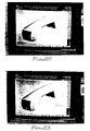
- Figure 6 is another illustration of a solid generation.
- two, two dimensional drawings are initially loaded and displayed as illustrated at label 600.
- the front face of one of the two dimensional drawings is selected as shown at label 610.
- the profile for the front face is selected next as depicted at label 620 .
- a back face is selected as shown at label 630 .
- the profile for the back face is selected as illustrated at label 640 , and the three dimensional solid is generated as illstrated at label 650 in Figure 7 .
- Figure 8 illustrates a circular extrusion.
- Two views of the object are initially drawn as illustrated at label 800 .
- a front face is selected as noted at label 810 .
- the front face profile is selected as illustrated at label 820 .
- the back face is selected at label 830 , and the profile of the back face is also selected as illustrated at label 840 .
- the resultant solid is displayed as shown at label 850 .
- FIG. 9 A further example involving a more complex geometry is presented in Figure 9 and 10 .
- Figure 9 a pair of two dimensional views of an object are presented at 900 and 910 respectively.
- a solid representation of the object is generated by selecting the front face and the back face. The generated solid is shown in Figure 10 .
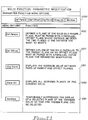
- the solid function parametric modification menu options are listed and their functions are elaborated upon.
- the menu options are displayed as they appear on a CAD display. If a user selects Def Parent at label 1100 , then the user is prompted to point to a plane of a solid that will function as the parent plane. The plane must be paired with a parallel offset plane whose distance is a variable that the user would like to change.
- Label 1120 lists the Define Offset menu option. This option allows a user to define a plane of the solid parallel to the parent plane as an offset plane.
- Label 1130 depicts the Change Parameter menu option. This item is selected to display the distance value between pairs of parent and offset planes.
- Label 1140 depicts the Show All menu option. This option is selected to display all planes that are not currently displayed for the solid object.
- Label 1150 is the No Show option which temporarily suppresses the display of a selected plane of the current solid so that a hidden plane can be selected.
- a user selects a solid object from the display as described in function block 1300 of Figure 13, and shown at label 1200 of Figure 12 .
- the user can remove some faces from the solid object using the No Show function as shown in function block 1310 of Figure 13 .
- the user defines a parent face by selecting a polygon of the solid as shown in function block 1320 and depicted at 1290 of Figure 12 .
- Offset faces parallel to the first face are selected next as shown in function block 1330 and depicted at 1270 and 1250 of Figure 12 .
- the distances between the offset faces 1252 and the distance between the parent face and the first offset face 1254 are calculated.
- the distance D1 1254 is a variable distance that will be adjusted.
- the distance D2 1252 is a fixed distance that remains constant during this operation.
- the logic set forth in Figure 14 is employed to make the face invisible on the display.
- the user initially selects a polygon (face) of a solid and converts the pointer to a loop id as shown in function block 1410 .
- the face is validated by searching the PFace table for the Face that contains the loop. If the face is found, then the selected polygon is a valid face as depicted in decision block 1420 . If not, then control flows to 1410 . If the face is valid, then the system sets the attribute of the selected polygon to visibility off as shown in 1430.
- the logic for defining a parent face is set forth in Figure 15 .
- the user begins by selecting a polygon of the solid object as shown in function block 1510 . Then, the system searches the PFace table to identify the Face that contains the loop as depicted in function block 1520 . If the Face is identified in decision block 1530 , then the Face ID as the Parent Face ID as shown in function block 1540 . However, if the Face ID is not found, then the Parent Face ID is set to a null value as shown in function block 1550 .
- the logic for defining an offset face is set forth in Figure 16.
- the user initially must select a polygon of the solid object as depicted in function block 1610 .
- the PFace table is searched for the Face ID of the selected polygon as depicted in function block 1620 .
- a search is next made to determine the type of the Face and based on the type, control is passed to one of two function blocks 1650 or 1660 . If the Face type is ordinary, then control is passed to function block 1660 where the distance between the Parent Face and the offset face is calculated and an entry to the parameter table is made to reflect the change.
- the Face Type is also changed to Offset Face. If the Face Type is already an Offset Face, then an invalid polygon has been selected as shown in function block 1640 , and control is passed to an error routine.
- An Offset Face can be redefined as a parent face for another offset face to form a nested relation.
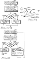
- Figure 17 presents the logic implementing the Change Parameter function.
- Function block 1700 indicates the f irst step is to select a polygon from the solid displayed on the graphic display. Then, the system searches through the PFace table for the face ID which the selected polygon is associated with as shown in function block 1710 . Subsequently, the face ID is used to determine the face type as depicted in decision block 1720 . If the face type is an ordinary face, then the polygon is highlighted on the display as depicted in function block 1730 , the distance from the origin tot he face is displayed, and control passes to function block 1760 .
- the PFace table is searched for the identifier of the parent face and the associated polygon as shown in function block 1740 . Then, the distance between the two offset faces is calculated, displayed and the polygons are highlighted as shown in function block 1750 .
- Function block 1760 depicts the next step, prompting the user to enter a new value for the distance via the keyboard.
- the new value is used to update the parameter table. If the polygon is a parent offset type, then modify the parameter of the selected face. If it is an ordinary face, then the parameter of the ordinary face is modified. Then, as illustrated in function block 1770 , the PFace table is converted into a Face table. Finally, the solid is regenerated by sending the Face table and the construction list to the solid modeler to generate the modified solid as shown in function block 1780 .
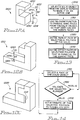
- Figure 12 shows a first solid 1200 and a second solid 1210 that are modified using the parametric entity function in accordance with the invention to create a finished assembly 1220.
- the distance D1 1254 in solid 1200 must be correlated with distance D3 1256 to complete the assembly correctly.
- the user initially selects D1 1254 as the variable distance from P1 1290 to O1 1270 .
- the distance D2 is defined as a fixed distance, and the variable distance is equated to D3 1256 . Thereafter, the system expands D1 1221 to comply with D3 1256 and completes the assembly.
- a surface can be created regardless of the facing.
- a surface has two faces, one is facing in, and the other is facing out.
- Surface normal is a reference for indicating the facing of a surface. It is also a vector for calculating the shading value. Since the surface normal is not specified during the creation of the surface, the image of the shaded surface may not appear correct to the viewer.
- Figures 20, 21, 22 and 23 Examples of surfaces displayed which employ the subject invention are presented in Figures 20, 21, 22 and 23.
- the logic for the processing is set forth in the flowcharts illustrated in Figures 18 and 19 .
- Figure 24 illustrates the variables behind the mathmatics used to implement some of the invention's logic.
- the detailed source code and data structures used to implement the logic is presented and described below.
- function block 1800 shows the first step which displays the shaded surfaces without user specified shading.
- the system To shade the surface, the system generates polygons to approximate the surface. By shading each polygon according to the normals to the surface on each vertex of the polygon the shaded surface is indicated appropriately.
- the system To shade a polygon, the system prepares a color table fo shading and calculates the intensity of each vertex of the polygon.
- the algorithm for preparing the color table is shown in the "C" listing set forth below.
- the logic has two steps. Step one: linearly interpolate the color values of red, green and blue (RGB) separately. To generate the three tables, (RGB) with constant incrementation from the specified ambient light value to the full color of the object. For the current display device, the shading color is generated into two-hundred levels.
- Step two the algorithm uses a cosine function on top of the result of step one to extend the range of the shading colors.
- the final color table will range from the specified ambient light value to shiny, bright color that will give the shaded object a shining spot when the reflection of the light source on the surface is toward the viewer's eye.
- Amb is the ambient light value.
- Ka indicates how much of the ambient light is reflected from the object's surface.
- Lv is the intensity of the light source.
- L 2400 is the light vector.
- N 2410 is normal to the surface at the vertex.
- (L x N) 2440 is the cosine value of the angle between L vector and N vector.
- Kd indicates how much of the diffused light reflected from the surface.
- R 2420 is the reflection vector.
- V 2430 is the vector from the vertex to the eye.
- (R x V) 2460 is the cosine of the angle between vector R and vector V.
- I Max(I[1], I[2], I[3],...I[n])
- I[i] is the illumination value for the ith light source.
- A amb * Ka
- D[i] Lv[i] * (L[i] x N);
- S[i] (Rx V) m
- the user is prompted to select a particular surface to display as shown in function block 1810 .
- the surface is selected by pointing with the cursor and using the pointer's coordinates to select the appropriate surface from the CADAM data base.
- the selected surface is erased as shown in function block 1820 .
- the surface data is rearranged as set forth in function block 1830 .
- the selected surface is shaded based on the rearranged information.
- a boundary surface stores four splines which form a closed boundary of the surface.
- the surface normal processing logic is set forth below.
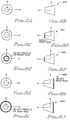
- Figure 20 shows a reverse surface normal of a top surface.
- Figure 21 shows a surface normal of a side surface.
- Figure 22 shows a reverse normal of a side surface, and
- Figure 23 shows a reverse normal of a front surface.
Abstract
Disclosed herein is a design system for designing, dynamically changing and displaying design drawings. The system allows a user to select a solid object from a display as the current, active object. The user then selects a first, parent face by selecting any point on a face of the solid object. Next, the user is prompted to select another point on a line of another face parallel to the first face. This operation defines the first offset face which is a variable distance from the first parent face. Subsequently, the user selects a point on a line to define a second parent face of the solid object. Then, the user selects a point on a line parallel to the second parent face. This defines the offset face and a corresponding distance between the two faces which is a fixed value.
Finally, the user is prompted to enter a new distance between the first parent face and the first offset face. This new value is used to generate a new solid based on a change to the variable distance between the first two faces and a corresponding shift in the location of the fixed distance between the second pair of faces and a resulting modification of the surface.
Description
- The present invention generally relates to improvements in computer aided design (CAD) systems and more particularly to a technique that correlates relationships between different parametric entities to enhance a CAD system.
- In CAD applications, it is important to be able to transform two-dimensional representations of objects into solid representations. The automobile and aircraft industries were two of the first to exploit this function for mechanical assemblies. Examples of general CAD systems are disclosed in US Patents 4,962,472; 4,849,913; and 4,912,664.
- US patent 4,849,913 discloses a method for the design and construction of composite parts by logically determining the geometric definitions for each ply contained in the composite part. This information can be used by subsequent analysis routines to determine the optimal method for manufacturing the part. Thus, the physical relationship of each of the parts and their correlating features are available for use by the system. However, the CAD system does not have any ability to dynamically alter the dimensions of a solid based on a change in distance between a plurality of faces.
- A face is used to refer to an unbounded plane. Unbounded refers to the fact that no limits are placed on the plane dimensions. A loop is a bounded area of a face. Boundary elements comprise the loop. For example, the four lines forming the edge of the plane are boundary elements. A Vertex is an endpoint of an edge. Vertices are calculated by finding the intersection of three intersecting plane equations. A loop table contains information defining all the loops contained in the solid object.
- In accordance with the present invention, there is now provided apparatus for performing a set od display operations to modify a three dimensional drawing on a graphic display, comprising:
- (a) means for storing a plurality of entities for defining a three dimensional drawing on a graphic display;
- (b) means for defining another variable entity based on an aspect of the three dimensional drawing;
- (c) means for modifying the variable entity; and
- (d) means for modifying the three dimensional drawing to reflect the changed variable entity.
- The present invention advantageously provides an improved apparatus for designing, dynamically changing and displaying three dimensional solid representations.
- Viewing a second aspect of the present invention, there is provided a method for performing a set of display operations to modify a three dimensional drawing on a graphic display, comprising the steps of:
- (a) storing a plurality of entities for defining a three dimensional drawing on a graphic display;
- (b) defining another variable entity based on an aspect of the three dimensional drawing;
- (c) modifying the variable entity; and
- (d) modifying the three dimensional drawing to reflect the changed variable entity.
- Thus, the present invention advantageously overcomes the need to pre-program relationships between CAD geometries and allows a user to dynamically alter a solid geometry on the basis of changes made in a face.
- A particularly preferred example of the present invention allows a user to select a solid object from a display as the current, active object. The user then selects a first, parent face by selecting any point on a face of the solid object. Next, the user is prompted to select another point on another face parallel to the first face. This operation defines the first offset face which is a variable distance from the first parent face.
- Subsequently, the user selects a point on the first offset face to redefine it as a second parent face of the solid object. Then, the user selects a point on a face parallel to the second parent face. This defines a nested relation between two parent/offset pairs which are parallel to each other.
- Finally, the user is prompted to enter a new distance between the first parent face and the first offset face. This new value is used to generate a new solid based on a change to the variable distance between the first two faces and a corresponding shift in the location of the fixed distance between the second pair of faces and a resulting modification of the solid.
- An embodiment of the present invention will now be described with reference to the accompanying drawings in which:
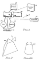
- Figure 1 is a block diagram of a computer in accordance with the present invention;
- Figure 2 is a flow chart of the solid logic in accordance with the present invention;
- Figure 3 is a flow chart of the solid logic for a tapered solid in accordance with the present invention;
- Figure 4 is an illustration of the steps used to generate an extruded solid in accordance with the present invention;
- Figure 5 is an illustration of the steps used to generate an extruded solid in accordance with the present invention;
- Figure 6 is an illustration of the steps used to generate a tapered solid in accordance with the present invention;
- Figure 7 is an illustration of a step used to generate a tapered solid in accordance with the present invention;
- Figure 8 is an illustration of a set of steps used to generate a tapered solid in accordance with the present invention;
- Figure 9 is an illustration of a pair of two dimensional drawings in accordance with the present invention;
- Figure 10 is an illustration of a solid model in accordance with the present invention;
- Figure 11 is an illustration of the parameter function menu options in accordance with the present invention;
- Figure 12 is an illustration of correlating parametric entities in accordance with the present invention;
- Figure 13 is a flowchart describing the logic of defining relationships between the faces of a solid object in accordance with the subject invention;
- Figure 14 is a flowchart describing the logic of the No Show function in accordance with the subject invention;
- Figure 15 is a flowchart of the logic implementing the defining a parent face in accordance with the subject invention;
- Figure 16 is a flowchart of the logic implementing the defining an offset face in accordance with the subject invention;
- Figure 17 is a flowchart of the logic implementing the Change Parameter function in accordance with the subject invention;
- Figure 18 is a flowchart depicting the logic of the shading surface normal in accordance with the subject invention;
- Figure 19 is a flowchart depicting the logic of the rearranging surface data in accordance with the subject invention;
- Figure 20 is an illustration of a reverse normal of a top surface in accordance with the subject invention;
- Figure 21 is an illustration of a select side surface display in accordance with the subject invention;
- Figure 22 is an illustration of a reverse normal of a side surface display in accordance with the subject invention;
- Figure 23 is an illustration of a reverse normal of a front surface in accordance with the subject invention; and
- Figure 24 is an illustration of defracted light from a display in accordance with the subject invention.
- With reference to Figure 1, the apparatus of the subject invention is a standard microprocessor such as that marketed by IBM under the product name of PS/2. The CPU 10 can he an 80386 or 80486 processor for example. The CPU 10 has Direct Memory Access (DMA) to the
RAM 20,Disk 30 andDiskette 40. The CPU 10 can also transmit information via theCommunication Link 50. - The CPU 10 also communicates to an attached graphic display to display information in EGA, VGA or other higher resolution modes. A mouse 70 is an optional cursor pointing device that is used to supplement the arrow keys of the
keyboard 80 for specifying precise pointings on thegraphic display 60. The keyboard is controlled by akeyboard adapter 82, including buffer means, in the CPU 10. Finally, a printer orplotter 89 can be attached to the CPU 10 to generate hardcopy of drawings. - The software used to awake the unique hardware features of this invention resides on the
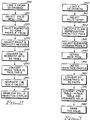
Disk 30 as do the drawings generated by a designer employing the invention. The software is also responsible for translating signals from the mouse/keyboard into appropriate system actions. - Figure 3 is a flowchart representing the logic in accordance with the invention. To generate a solid from a two dimensional drawing, the drawing is first loaded into the computer memory as shown in
function block 200. The drawing should contain multiple two dimensional views of an object. The user then selects the appropriate menu selection item as depicted ininput block 210. Then, the user selects elements to form a profile for the extrusion operation as depicted ininput block 220. The elements are lines and circles on the two dimensional views from which to generate the solid model. The pointers to the selected elements are stored in the data structure set forth below.


- The geometric elements are selected in a clockwise or counter-clockwise sequence. When all of the necessary elements have been selected, then menu item END is selected to indicate completion. The data structure is used to store this information in a manageable fashion for further processing in accordance with the subject invention.
- The user selects front and back cutting faces by selecting lines in the views other than the profile view as depicted in
input block 230. Next, the selected two dimensional elements are converted into three dimensional geometries as set forth ininput block 240. So, for example, a line becomes an unbounded plane, a circle becomes an unbounded cylinder, and a spline becomes a ruled face. The faces are stored in the PFace data structure set forth below. - A Face Table is a list of faces that form the boundary of a solid. The Face Table contains plane, cylinders and free form surface information. The Face Table serves as an interface between parametric design and the solid modeler. A PFace Table is a particular face table used for parametric design. It contains parameterized faces, a parameter table and a construction list for building a solid from the faces. A construction list contains a description of how each part of the solid is created and what faces are used to form the component.


- Finally, the solid object is displayed on the graphics display as shown in
output block 270. The attached listing is the source code used to implement the various transformations and display of graphic information.


- An alternative embodiment of the invention allows a tapered display of a solid object to be created. The logic implementing this function is set forth in Figure 3. The initial steps set forth in
function block 300 are identical to the solid generation discussed above. A two dimensional drawing is loaded. The user selects the solid taper menu function ininput block 310. Then, the user is prompted to select a plane representing the front cut face as shown ininput block 320. This is done by positioning the cursor on lines other than the profile view. Next, the user is prompted to select elements forming a profile of the front face as shown ininput block 330. The user selects the necessary two dimensional geometries in the profile view to form a profile for taper. Then the end menu is selected to indicate completion of profile processing. -
Input block 340 depicts the user selection of the back face as the next step. The user selects lines in views other than the profile view to form a profile for the taper operation as shown ininput block 350. When the selection process is complete, the end menu item is selected. Then, infunction block 360, the two dimensional geometries are converted to three dimensional faces as depicted infunction block 370 and a solid representation is generated. This processing includes conversion of the two dimensional geometries to three dimensional geometries and the corresponding conversion of data structures as discussed above. Finally, the solid is displayed as depicted inoutput block 380. The data structure attached below is used to store the solid object for subsequent display.


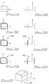
- In Figures 4, 5, 6, 7 and 8, examples of solid generations employing the subject invention are illustrated. In Figure 4, a front view and a side view of a two dimensional object are presented at
label label 420. Next, the back face is selected from the side view as indicated atlabel 430, and finally, four lines of the back face are selected to form the profile as shown atlabel 440. This information is used to generate a three dimensional solid object as illustrated atlabel 450. - Figure 5 is another example of an extrusion. First, three lines and an arc are selected as a profile for extrusion as depicted at
label 500. Then, two two lines from a side view are selected to complete the operation as shown atlabel 510. The solid object is then generated as shown atlabel 520. - Figure 6 is another illustration of a solid generation. Again, two, two dimensional drawings are initially loaded and displayed as illustrated at label 600. Then, the front face of one of the two dimensional drawings is selected as shown at
label 610. The profile for the front face is selected next as depicted atlabel 620. Next, a back face is selected as shown atlabel 630. Finally, the profile for the back face is selected as illustrated atlabel 640, and the three dimensional solid is generated as illstrated atlabel 650 in Figure 7. - Figure 8 illustrates a circular extrusion. Two views of the object are initially drawn as illustrated at
label 800. Then, a front face is selected as noted atlabel 810. Next, the front face profile is selected as illustrated atlabel 820. Finally, the back face is selected atlabel 830, and the profile of the back face is also selected as illustrated atlabel 840. The resultant solid is displayed as shown at label 850. - A further example involving a more complex geometry is presented in Figure 9 and 10. In Figure 9, a pair of two dimensional views of an object are presented at 900 and 910 respectively. A solid representation of the object is generated by selecting the front face and the back face. The generated solid is shown in Figure 10.
- In Figure 11, the solid function parametric modification menu options are listed and their functions are elaborated upon. At
label 1000, the menu options are displayed as they appear on a CAD display. If a user selects Def Parent atlabel 1100, then the user is prompted to point to a plane of a solid that will function as the parent plane. The plane must be paired with a parallel offset plane whose distance is a variable that the user would like to change. -
Label 1120 lists the Define Offset menu option. This option allows a user to define a plane of the solid parallel to the parent plane as an offset plane.Label 1130 depicts the Change Parameter menu option. This item is selected to display the distance value between pairs of parent and offset planes.Label 1140 depicts the Show All menu option. This option is selected to display all planes that are not currently displayed for the solid object.Label 1150 is the No Show option which temporarily suppresses the display of a selected plane of the current solid so that a hidden plane can be selected. - To commence a parametric design a user selects a solid object from the display as described in
function block 1300 of Figure 13, and shown atlabel 1200 of Figure 12. Optionally, the user can remove some faces from the solid object using the No Show function as shown infunction block 1310 of Figure 13. Then, the user defines a parent face by selecting a polygon of the solid as shown infunction block 1320 and depicted at 1290 of Figure 12. Offset faces parallel to the first face are selected next as shown infunction block 1330 and depicted at 1270 and 1250 of Figure 12. The distances between the offset faces 1252 and the distance between the parent face and the first offsetface 1254 are calculated. Thedistance D1 1254 is a variable distance that will be adjusted. Whereas, thedistance D2 1252 is a fixed distance that remains constant during this operation. - If the user selects the NoShow function then the logic set forth in Figure 14 is employed to make the face invisible on the display. The user initially selects a polygon (face) of a solid and converts the pointer to a loop id as shown in function block 1410. Then, the face is validated by searching the PFace table for the Face that contains the loop. If the face is found, then the selected polygon is a valid face as depicted in
decision block 1420. If not, then control flows to 1410. If the face is valid, then the system sets the attribute of the selected polygon to visibility off as shown in 1430. - The logic for defining a parent face is set forth in Figure 15. As above, the user begins by selecting a polygon of the solid object as shown in
function block 1510. Then, the system searches the PFace table to identify the Face that contains the loop as depicted infunction block 1520. If the Face is identified indecision block 1530, then the Face ID as the Parent Face ID as shown infunction block 1540. However, if the Face ID is not found, then the Parent Face ID is set to a null value as shown infunction block 1550. - The logic for defining an offset face is set forth in Figure 16. The user initially must select a polygon of the solid object as depicted in
function block 1610. Then, the PFace table is searched for the Face ID of the selected polygon as depicted infunction block 1620. A search is next made to determine the type of the Face and based on the type, control is passed to one of twofunction blocks block 1660 where the distance between the Parent Face and the offset face is calculated and an entry to the parameter table is made to reflect the change. Finally, the Face Type is also changed to Offset Face. If the Face Type is already an Offset Face, then an invalid polygon has been selected as shown infunction block 1640, and control is passed to an error routine. An Offset Face can be redefined as a parent face for another offset face to form a nested relation. - Figure 17 presents the logic implementing the Change Parameter function.
Function block 1700 indicates the first step is to select a polygon from the solid displayed on the graphic display. Then, the system searches through the PFace table for the face ID which the selected polygon is associated with as shown in function block 1710. Subsequently, the face ID is used to determine the face type as depicted indecision block 1720. If the face type is an ordinary face, then the polygon is highlighted on the display as depicted infunction block 1730, the distance from the origin tot he face is displayed, and control passes to functionblock 1760. However, if the face type is an offset face, then the PFace table is searched for the identifier of the parent face and the associated polygon as shown infunction block 1740. Then, the distance between the two offset faces is calculated, displayed and the polygons are highlighted as shown infunction block 1750. -
Function block 1760 depicts the next step, prompting the user to enter a new value for the distance via the keyboard. The new value is used to update the parameter table. If the polygon is a parent offset type, then modify the parameter of the selected face. If it is an ordinary face, then the parameter of the ordinary face is modified. Then, as illustrated infunction block 1770, the PFace table is converted into a Face table. Finally, the solid is regenerated by sending the Face table and the construction list to the solid modeler to generate the modified solid as shown infunction block 1780. - Figure 12 shows a first solid 1200 and a second solid 1210 that are modified using the parametric entity function in accordance with the invention to create a
finished assembly 1220. Thedistance D1 1254 in solid 1200 must be correlated with distance D3 1256 to complete the assembly correctly. Thus, the user initially selectsD1 1254 as the variable distance from P1 1290 toO1 1270. The distance D2 is defined as a fixed distance, and the variable distance is equated to D3 1256. Thereafter, the system expandsD1 1221 to comply with D3 1256 and completes the assembly. - In a normal CAD system, a surface can be created regardless of the facing. However, a surface has two faces, one is facing in, and the other is facing out. Depending on the position or orientation of teh surface in a composite object. Surface normal is a reference for indicating the facing of a surface. It is also a vector for calculating the shading value. Since the surface normal is not specified during the creation of the surface, the image of the shaded surface may not appear correct to the viewer.
- Examples of surfaces displayed which employ the subject invention are presented in Figures 20, 21, 22 and 23. The logic for the processing is set forth in the flowcharts illustrated in Figures 18 and 19. Figure 24 illustrates the variables behind the mathmatics used to implement some of the invention's logic. Finally, the detailed source code and data structures used to implement the logic is presented and described below.
- Referring to Figure 18,
function block 1800 shows the first step which displays the shaded surfaces without user specified shading. To shade the surface, the system generates polygons to approximate the surface. By shading each polygon according to the normals to the surface on each vertex of the polygon the shaded surface is indicated appropriately. - To shade a polygon, the system prepares a color table fo shading and calculates the intensity of each vertex of the polygon. The algorithm for preparing the color table is shown in the "C" listing set forth below. The logic has two steps. Step one: linearly interpolate the color values of red, green and blue (RGB) separately. To generate the three tables, (RGB) with constant incrementation from the specified ambient light value to the full color of the object. For the current display device, the shading color is generated into two-hundred levels.
- Step two: the algorithm uses a cosine function on top of the result of step one to extend the range of the shading colors. The final color table will range from the specified ambient light value to shiny, bright color that will give the shaded object a shining spot when the reflection of the light source on the surface is toward the viewer's eye.


- To shade a polygon, the illumination value of each vertex must be calculated. Illumination (I) is calculated with the following equation.

- Referring to Figure 24, Amb is the ambient light value. Ka indicates how much of the ambient light is reflected from the object's surface.
- Lv is the intensity of the light source.
L 2400 is the light vector.N 2410 is normal to the surface at the vertex. (L x N) 2440 is the cosine value of the angle between L vector and N vector. Kd indicates how much of the diffused light reflected from the surface.R 2420 is the reflection vector.V 2430 is the vector from the vertex to the eye. (R x V) 2460 is the cosine of the angle between vector R and vector V. - Since the illumination value is a sum of the ambient factor, diffuse factor and specular factor, the result may not fall within the acceptable range. Especially, when there are multiple light sources and the graphic hardware has a limited resolution. Thus, the following modification to the original equation is made to enhance shading.


- When the intensity of each vertex of a polygon is resolved, the intensity is converted to an index to the color table. (See data structure listing below)


- Then, the user is prompted to select a particular surface to display as shown in
function block 1810. The surface is selected by pointing with the cursor and using the pointer's coordinates to select the appropriate surface from the CADAM data base. Next, the selected surface is erased as shown infunction block 1820. Then, the surface data is rearranged as set forth infunction block 1830. - Four kinds of surface data can be rearranged, ruled surfaces, revolved surfaces, boundary surfaces, boundary surfaces and skin surfaces. The data structure of these surfaces is set forth below.


- For ruled surfaces or revolved surfaces, the sequences of the control points are inverted and the knot sequences of its splines are calculated. For boundary surfaces, the sequences of the control points of spline one and two are inverted, and their knot sequences are recalculated. Splines three and four are swapped. For skin surfaces, each profile spline has its corresponding control points inverted and the knot sequences are recalculated Figure 19 sets forth the detailed logic presented in
function blocks - Finally, as shown in
function block 1840, the selected surface is shaded based on the rearranged information. - As introduced, a boundary surface stores four splines which form a closed boundary of the surface. The surface normal processing logic is set forth below.


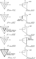
- Four examples of shaded surfaces are presented in Figures 20, 21, 22 and 23. Figure 20 shows a reverse surface normal of a top surface. Figure 21 shows a surface normal of a side surface. Figure 22 shows a reverse normal of a side surface, and Figure 23 shows a reverse normal of a front surface.
- While the invention has been described in terms of a preferred embodiment in a specific system environment, those skilled in the art recognize that the invention can be practiced, with modification, in other and different hardware and software environments within the spirit and scope of the appended claims.
Claims (16)
- Apparatus for performing a set of display operations to modify a three dimensional drawing on a graphic display, comprising:(a) means for storing a plurality of entities for defining a three dimensional drawing on a graphic display;(b) means for defining another variable entity based on an aspect of the three dimensional drawing;(c) means for modifying the variable entity; and(d) means for modifying the three dimensional drawing to reflect the changed variable entity.
- Apparatus as recited in claim 1, further comprising data structure means for storing three dimensional drawing information.
- Apparatus as recited in claim 1, further comprising data structure means for storing entity information.
- Apparatus as recited in claim 1, further comprising means for substituting an entity form another drawing as the variable entity.
- Apparatus as recited in claim 1, further comprising means for specifying the location where the drawing should appear on the graphic display.
- Apparatus as recited in claim 1, further comprising means for joining two, three dimensional drawings.
- Apparatus as recited in claim 1, further comprising means for making faces of a solid transparent.
- Apparatus as recited in claim 1, further comprising means for defining a pair of parent/offsets parallel planes to form a nested relationship.
- A method for performing a set of display operations to modify a three dimensional drawing on a graphic display, comprising the steps of:(a) storing a plurality of entities for defining a three dimensional drawing on a graphic display;(b) defining another variable entity based on an aspect of the three dimensional drawing;(c) modifying the variable entity; and(d) modifying the three dimensional drawing to reflect the changed variable entity.
- A method as recited in claim 9, further comprising the step of creating a data structure to save three dimensional drawing information.
- A method as recited in claim 9, further comprising data structure means for storing entity information.
- A method as recited in claim 9, further comprising the step of substituting a first entity from a first drawing for a second variable entity from another drawing.
- A method as recited in claim 9, further comprising the step of specifying the location where the drawing should appear on the graphic display.
- A method as recited in claim 9, further comprising the step of joining two, three dimensional drawings.
- A method as recited in claim 9, further comprising the step of making faces of a solid transparent.
- A method as recited in claim 9, further comprising the step of defining a pair of parent/offsets parallel planes to form a nested relationship.
Applications Claiming Priority (2)
| Application Number | Priority Date | Filing Date | Title |
|---|---|---|---|
| US61818790A | 1990-11-26 | 1990-11-26 | |
| US618187 | 1990-11-26 |
Publications (2)
| Publication Number | Publication Date |
|---|---|
| EP0488569A2 true EP0488569A2 (en) | 1992-06-03 |
| EP0488569A3 EP0488569A3 (en) | 1993-03-10 |
Family
ID=24476676
Family Applications (1)
| Application Number | Title | Priority Date | Filing Date |
|---|---|---|---|
| EP19910310669 Withdrawn EP0488569A3 (en) | 1990-11-26 | 1991-11-20 | Enhanced computer aided design system |
Country Status (4)
| Country | Link |
|---|---|
| US (1) | US6115046A (en) |
| EP (1) | EP0488569A3 (en) |
| JP (1) | JPH05324775A (en) |
| CA (1) | CA2055545A1 (en) |
Families Citing this family (7)
| Publication number | Priority date | Publication date | Assignee | Title |
|---|---|---|---|---|
| US6084587A (en) * | 1996-08-02 | 2000-07-04 | Sensable Technologies, Inc. | Method and apparatus for generating and interfacing with a haptic virtual reality environment |
| US6552722B1 (en) * | 1998-07-17 | 2003-04-22 | Sensable Technologies, Inc. | Systems and methods for sculpting virtual objects in a haptic virtual reality environment |
| US6421048B1 (en) | 1998-07-17 | 2002-07-16 | Sensable Technologies, Inc. | Systems and methods for interacting with virtual objects in a haptic virtual reality environment |
| US7990374B2 (en) * | 2004-06-29 | 2011-08-02 | Sensable Technologies, Inc. | Apparatus and methods for haptic rendering using data in a graphics pipeline |
| US7880737B2 (en) * | 2005-03-22 | 2011-02-01 | Vijayvardhan Elchuri | Graphical method and system for making drawings directly in three-dimensions on a computer monitor or other display device |
| US7639249B2 (en) * | 2006-05-05 | 2009-12-29 | Microsoft Corporation | Direct inset beveling of geometric figures |
| USD655460S1 (en) * | 2010-06-17 | 2012-03-06 | Reef One Limited | Aquarium |
Family Cites Families (11)
| Publication number | Priority date | Publication date | Assignee | Title |
|---|---|---|---|---|
| US4684990A (en) * | 1985-04-12 | 1987-08-04 | Ampex Corporation | Method and apparatus for combining multiple video images in three dimensions |
| US5124693A (en) * | 1985-10-29 | 1992-06-23 | International Business Machines | Three dimensional graphic display with user defined vanishing point |
| JPH0756678B2 (en) * | 1985-11-01 | 1995-06-14 | 株式会社日立製作所 | Interactive shape modeling system |
| US5003498A (en) * | 1986-01-13 | 1991-03-26 | Hitachi, Ltd. | Graphic display method |
| JPH0614337B2 (en) * | 1986-07-16 | 1994-02-23 | 本田技研工業株式会社 | How to change the shape model |
| US4809065A (en) * | 1986-12-01 | 1989-02-28 | Kabushiki Kaisha Toshiba | Interactive system and related method for displaying data to produce a three-dimensional image of an object |
| JPH0685128B2 (en) * | 1987-03-12 | 1994-10-26 | フアナツク株式会社 | Automatic programming system |
| US4849913A (en) * | 1987-04-10 | 1989-07-18 | The Boeing Company | Method for the design and construction of composite parts |
| GB8728836D0 (en) * | 1987-12-10 | 1988-01-27 | Quantel Ltd | Electronic image processing |
| US4912664A (en) * | 1988-02-01 | 1990-03-27 | Mentor Graphics Corporation | Method and apparatus for generating a mesh for finite element analysis |
| US5265197A (en) * | 1988-12-23 | 1993-11-23 | Kabushiki Kaisha Toshiba | Geometric modeling apparatus |
-
1991
- 1991-11-14 CA CA002055545A patent/CA2055545A1/en not_active Abandoned
- 1991-11-18 JP JP3328319A patent/JPH05324775A/en active Pending
- 1991-11-20 EP EP19910310669 patent/EP0488569A3/en not_active Withdrawn
-
1995
- 1995-01-03 US US08/368,239 patent/US6115046A/en not_active Expired - Fee Related
Non-Patent Citations (1)
| Title |
|---|
| TRANSACTIONS OF THE INSTITUTE OF ELECTRONICS, INFORMATION AND COMMUNICATION ENGINEERS OF JAPAN vol. E70, no. 12, December 1987, TOKYO JP pages 1220 - 1228 MEKHABUNCHAKIJ K. ET AL. 'interactive solid design through 2d representations' * |
Also Published As
| Publication number | Publication date |
|---|---|
| CA2055545A1 (en) | 1992-05-27 |
| JPH05324775A (en) | 1993-12-07 |
| EP0488569A3 (en) | 1993-03-10 |
| US6115046A (en) | 2000-09-05 |
Similar Documents
| Publication | Publication Date | Title |
|---|---|---|
| US5561748A (en) | Method and apparatus for creating solid models from two-dimensional drawings on a graphics display | |
| JP4430149B2 (en) | Apparatus and method for manually selecting, displaying and repositioning dimensional information of part model | |
| EP1804187B1 (en) | Process for displaying objects in a PLM database and apparatus implementing this process | |
| US9153072B2 (en) | Reducing the size of a model using visibility factors | |
| JP3275920B2 (en) | Scientific figure display method | |
| US5774130A (en) | Computer animation generator creating hierarchies of models for rapid display | |
| EP0391572A2 (en) | Method for employing a hierarchical display list in global rendering | |
| US8823706B2 (en) | Method, program and product edition system for visualizing objects displayed on a computer screen | |
| EP3040946B1 (en) | Viewpoint selection in the rendering of a set of objects | |
| GB2325835A (en) | Volumetric pre-clipping method in a volumetric rendering system | |
| EP0658859A2 (en) | Method and apparatus for interlocking graphical objects | |
| US6115046A (en) | Method and apparatus for generating three dimensional drawing on a graphics display | |
| US6879327B1 (en) | Creating gradient fills | |
| JPH05346957A (en) | Device and method for presenting shape feature quantity | |
| EP0488578A2 (en) | Enhanced computer aided design shading | |
| US5926183A (en) | Efficient rendering utilizing user defined rooms and windows | |
| JP2006099422A (en) | Image processing system and program | |
| Woodwark | Generating wireframes from set-theoretic solid models by spatial division | |
| Kameyama et al. | A direct 3-D shape modeling system | |
| JPH08123835A (en) | Shape design support device | |
| JP2010271828A (en) | Solid shape generation system and method | |
| van Wijk et al. | Some issues in designing user interfaces to 3D raster graphics | |
| JP3268667B2 (en) | Interactive polygon selection device | |
| JP3092241B2 (en) | 3D shape design method and display method | |
| JPH0863501A (en) | Graphic processor and graphic processing method |
Legal Events
| Date | Code | Title | Description |
|---|---|---|---|
| PUAI | Public reference made under article 153(3) epc to a published international application that has entered the european phase |
Free format text: ORIGINAL CODE: 0009012 |
|
| AK | Designated contracting states |
Kind code of ref document: A2 Designated state(s): DE FR GB IT |
|
| 17P | Request for examination filed |
Effective date: 19920917 |
|
| PUAL | Search report despatched |
Free format text: ORIGINAL CODE: 0009013 |
|
| AK | Designated contracting states |
Kind code of ref document: A3 Designated state(s): DE FR GB IT |
|
| STAA | Information on the status of an ep patent application or granted ep patent |
Free format text: STATUS: THE APPLICATION HAS BEEN WITHDRAWN |
|
| 18W | Application withdrawn |
Withdrawal date: 19961014 |