-
The present invention generally relates to improvements in computer aided design (CAD) systems and more particularly to a technique for shading surfaces to enhance perception of the same.
-
In CAD applications, it is important to be able to transform two-dimensional representations of objects into solid representations. The automobile and aircraft industries were two of the first to exploit this function for mechanical assemblies. Examples of general CAD systems are disclosed in US Patents 4,962,472; 4,849,913; and 4,912,664.
-
US patent 4,849,913 discloses a method for the design and construction of composite parts by logically determining the geometric definitions for each ply contained in the composite part. This information can be used by subsequent analysis routines to determine the optimal method for manufacturing the part. Thus, the physical relationship of each of the parts and their correlating features are available for use by the system. However, the CAD system does not have any ability to dynamically alter the dimensions of a solid based on a change in distance between a plurality of faces.
-
A face is used to refer to an unbounded place. Unbounded refers to the fact that no limits are paced on the plane dimensions. A loop is a bounded area of a face. Boundary elements comprise the loop. For example, the four lines forming the edge of the plane are boundary elements. A Vertex is an endpoint of an edge. Vertices are calculated by finding the intersection of three (3) intersecting plane equations. A loop table contains information defining all the loops contained in the solid object.
-
In accordance with the present invention, there is now provided apparatus for performing a set of display operations to modify a three dimensional drawing on a graphic display, comprising:
- (a) means for storing information defining a three dimensional drawing on the graphic display;
- (b) means for generating a drawing on the graphic display based on the information;
- (c) means for selecting a surface of the drawing;
- (d) means for modifying the information and displaying the drawing with the selected surface appearing in the foreground of the display.
-
Thus, the present invention advatageously overcomes the limitation of the prior art to provide an accurate, realistic representation of a three dimensional drawing on a graphic display.
-
Viewing a second aspect of the present invention, there is now provided a method for performing a set of display operations to modify a three dimensional drawing on a graphic display, comprising the steps of:
- (a) storing information defining a three dimensional drawing on the graphic display;
- (b) generating a drawing on the graphic display based on the information;
- (c) selecting a surface of the drawing;
- (d) modifying the information and displaying the drawing with the selected surface appearing in the foreground of the display.
-
The present invention thus provides an improved apparatus for and method of designing, dynamically changing and displaying three dimensional shaded representations.
-
A preferred embodiment of the preset invention enhances the display of three dimensional surfaces by using an algorithm to build a color table for shading and allowing the user to invert the normal of a surface to render a realistic image. The color table contains two hundred color entries. The logic adds a non-linear intensity factor on top of a linear incremental function to generate a color table continuous intensity from low to high. The color table is regenerated every time the user changes the shading color. Based on the current values in the color table, the shaded surface is accentuated according to the viewing and light position. The user selects the incorrect surfaces and the system inverts the surface normal to the deleted surface and reshades the surface to accent the realistic view.
-
A preferred embodiment of the present invention will now be described with reference to the accompanying drawings in which:
- Figure 1 is a block diagram of a computer in accordance with the present invention;
- Figure 2 is a flow chart of the solid logic in accordance with the present invention;
- Figure 3 is a flow chart of the solid logic for a tapered solid in accordance with the present invention;
- Figure 4 is an illustration of the steps used to generate an extruded solid in accordance wit the present invention;
- Figure 5 is an illustration of the steps used to generate an extruded solid in accordance with the present invention;
- Figure 6 is an illustratior of the steps used to generate a tapered solid in accordance with the present invention;
- Figure 7 is an illustration of a step used to generate a tapered solid in accordance with the present invention;
- Figure 8 is an illustration of a set of steps used to generate a tapered solid in accordance wit the present invention;
- Figure 9 is an illustration of a pair of two dimensional drawings in accordance with the present invention;
- Figure 10 is an illustration of a solid model in accordance with the present invention;
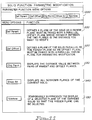
- Figure 11 is an illustration of the parameter function menu options in accordance with the present invention;
- Figure 12 is an illustration of correlating parametric entities in accordance with the present invention;
- Figure 13 is a flowchart describing the logic of defining relationships between the faces of a solid object in accordance with the subject invention;
- Figure 14 is a flowchart describing the logic of the No Show function in accordance with the subject invention;
- Figure 15 is a flowchart of the logic implemeting the defining a parent face in accordance with the subject invention;
- Figure 16 is a flowchart of the logic implementing the defining an offset face in accordance with the subject invention;
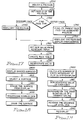
- Figure 17 is a flowchart of the logic implementing the Change Parameter function in accordance with the subject invention;
- Figure 18 is a flowchart depicting the logic of the shading surface normal in accordance with the subject invention;
- Figure 19 is a flowchart depicting the logic of the rearranging surface data in accordance with the subject invention;
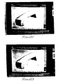
- Figure 20 is an illustration of a reverse normal of a top surface in accordance with the subject invention;
- Figure 21 is an illustration of a select side surface display in accordance with the subject invention;
- Figure 22 is an illustration of a reverse normal of a side surface display in accordance with the subject invention;
- Figure 23 is an illustration of a reverse normal of a front surface in accordance with the subject invention; and
- Figure 24 is an illustration of defracted light from a display in accordance with the subject invention.
DETAILED DESCRIPTION OF THE INVENTION
-
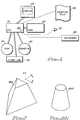
With reference to Figure 1, the apparatus of the subject invention is a standard microprocessor such as that marketed by IBM under the product name of PS/2. The CPU 10 can bean 80386 or 80486 processor for example. The CPU 10 has Direct Memory Access (DMA) to the RAM 20, Disk 30 and Diskette 40. The CPU 10 can also transmit information via the Communication Link 50.
-
The CPU 10 also communicates to an attached graphic display to display information in EGA, VGA or other higher resolution modes. A mouse 70 is an optional cursor pointing device that is used to supplement the arrow keys of the keyboard 80 for specifying precise pointings on the graphic display 60. The keyboard is controlled by a keyboard adapter 82, including buffer means, in the CPU 10. Finally, a printer or plotter 89 can be attached to the CPU 10 to generate hardcopy of drawings.
-
The software used to awake the unique hardware features of this invention resides on the Disk 30 as do the drawings generated by a designer employing the invention. The software is also responsible for translating signals from the mouse/keyboard into appropriate system actions.
-
Figure
3 is a flowchart representing the logic in accordance with the invention. To generate a solid from a two dimensional drawing, the drawing is first loaded into the computer memory as shown in
function block 200. The drawing should contain multiple two dimensional views of an object. The user then selects the appropriate menu selection item as depicted in
input block 210. Then, the user selects elements to form a profile for the extrusion operation as depicted in
input block 220. The elements are lines and circles on the two dimensional views from which to generate the solid model. The pointers to the selected elements are stored in the data structure set forth below.
-
The geometric elements are selected in a clockwise or counter-clockwise sequence. When all of the necessary elements have been selected, then menu item END is selected to indicate completion. The data structure is used to store this information in a manageable fashion for further processing in accordance with the subject invention.
-
The user selects front and back cutting faces by selecting lines in the views other than the profile view as depicted in input block 230. Next, the selected two dimensional elements are converted into three dimensional geometries as set forth in input block 240. So, for example, a line becomes an unbounded plane, a circle becomes an unbounded cylinder, and a spline becomes a ruled face. The faces are stored in the PFace data structure set forth below.
-
A Face Table is a list of faces that form the boundary of a solid. The Face Table contains plane, cylinders and free form surface information. The Face Table serves as an interface between parametric design and the solid modeler. A PFace Table is a particular face table used for parametric design. It contains parameterized faces, a parameter table and a construction list for building a solid from the faces. A construction list contains a description of how each part of the solid is created and what faces are used to form the component.
-
The next step converts the PFace data structure to a Face data structure for input into the solid modeler. The Face data structure is set forth below.
-
An alternative embodiment of the invention allows a tapered display of a solid object to be created. The logic implementing this function is set forth in Figure 3. The initial steps set forth in function block 300 are identical to the solid generation discussed above. A two dimensional drawing is loaded. The user selects the solid taper menu function in input block 310. Then, the user is prompted to select a plane representing the front cut face as shown in input block 320. This is done by positioning the cursor on lines other than the profile view. Next, the user is prompted to select elements forming a profile of the front face as shown in input block 330. The user selects the necessary two dimensional geometries in the profile view to form a profile for taper. Then the end menu is selected to indicate completion of profile processing.
-
Input block 340 depicts the user selection of the back face as the next step. The user selects lines in views other than the profile view to form a profile for the taper operation as shown in
input block 350. When the selection process is complete, the end menu item is selected. Then, in
function block 360, the two dimensional geometries are converted to three dimensional faces as depicted in
function block 370 and a solid representation is generated. This processing includes conversion of the two dimensional geometries to three dimensional geometries and the corresponding conversion of data structures as discussed above. Finally, the solid is displayed as depicted in
output block 380. The data structure attached below is used to store the solid object for subsequent display.
-
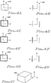
In Figures 4, 5, 6, 7 and 8, examples of solid generations employing the subject invention are illustrated. In Figure 4, a front view and a side view of a two dimensioal object are presented at label 400 and 410. To generate a solid rendition of the two, two dimensional views, the user initially selects the four lines as the profile for extrusion on the front face at label 420. Next, the back face is selected from the side view as indicated at label 430, and finally, four lines of the back face are selected to form the profile as shown at label 440. This information is used to generate a three dimensional solid object as illustrated at label 450.
-
Figure 5 is another example of a extrusion. First, three lines and an arc are selected as a profile for extrusion as depicted at label 500. Then, two two lines from a side view are selected to complete the operation as shown at label 510. The solid object is then generated as shown at label 520.
-
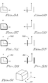
Figure 6 is another illustration of a solid generation. Again, two, two dimensional drawings are initially loaded and displayed as illustrated at label 600. Then, the front face of one the two dimensional drawings is selected as show at label 610. The profile for the front face is selected next as depicted at label 620. Next, a back face is selected as shown at label 630. Finally, the profile for the back face is selected as illustrated at label 640, and the three dimensional solid is generated as illustrated at label 650 in Figure 7.
-
Figure 8 illustrates a circular extrusion. Two views of the object are initially drawn as illustrated at label 800. Then, a front face is selected as noted at label 810. Next, the front face profile is selected as illustrated at label 820. Finally, the back face is selected at label 830, and the profile of the back face is also selected as illustrated at label 840. The resultant solid is displayed as shown at label 850.
-
A further example involving a more complex geometry is presented in Figure 9 and 10. In Figure 9, a pair of two dimensional views of an object are presented at 900 and 910 respectively. A solid representation of the object is generated by selecting the front face and the back face. The generated solid is shown in Figure 10.
Parametric Entities
-
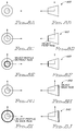
In Figure 11, the solid function parametric modification menu options are listed and their fuctions are elaborated upon. At label 1000, the menu options are displayed as they appear on a CAD display. If a user selects Def Parent at label 1100, then the user is prompted to point to a plane of a solid that will function as the parent plane. The plane must be paired with a parallel offset plane whose distance is a variable that the user would like to change.
-
Label 1120 lists the Define Offset menu option. This option allows a user to define a plane of the solid parallel to the parent plane as an offset plane. Label 1130 depicts the Change Parameter menu option. This item is selected to display the distance value between pairs of parent and offset planes. Label 1140 depicts the Show All menu option. This option is selected to display all planes that are not currently displayed for the solid object. Label 1150 is the No Show option which temporarily suppresses the display of a selected plane of the current solid so that a hidden plane can be selected.
-
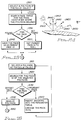
To commence a parametric design a user selects a solid object from the display as described in function block 1300 of Figure 13, and shown at label 1200 of Figure 12. Optionally, the user can remove some faces from the solid object using the No Show function as shown in function block 1310 of Figure 13. Then, the user defines a parent face by selecting a polygon of the solid as shown in function block 1320 and depicted at 1290 of Figure 12. Offset faces parallel to the first face are selected next as shown in function block 1330 and depicted at 1270 and 1250 of Figure 12. The distances between the offset faces 1252 and the distance between the parent face and the first offset face 1254 are calculated. The distance D1 1254 is a variable distance that will be adjusted. Whereas, the distance D2 1252 is a fixed distance that remains constant during this operation.
-
If the user selects the NoShow function then the logic set forth in Figure 14 is employed to make the face invisible on the display. The user initially selects a polygon (face) of a solid and converts the pointer to a loop id as shown in function block 1410. Then, the face is validated by searching the PFace table for the Face that contains the loop. If the face is found, then the selected polygon is a valid face as depicted in decision block 1420. If not, then control flows to 1410. If the face is valid, then the system sets the attribute of the selected polygon to visibility off as shown in 1430.
-
The logic for defining a parent face is set forth in Figure 15. As above, the user begins by selecting a polygon of the solid object as shown in function block 1510. Then, the system searches the PFace table to identify the Face that contains the loop as depicted in function block 1520. If the Face is identified in decision block 1530, then the Face ID as the Parent Face ID as show in function block 1540. However, if the Face ID is not found, then the Parent Face ID is set to a null value as shown in function block 1550.
-
The logic for defining an offset face is set forth in Figure 16. The user initially must select a polygon of the solid object as depicted in function block 1610. Then, the PFace table is searched for the Face ID of the selected polygon as depicted in function block 1620. A search is next made to determine the type of the Face and based on the type, control is passed to one of two function blocks 1650 or 1660. If the Face type is ordinary, then control is passed to function block 1660 where the distance between the Parent Face and the offset face is calculated and an entry to the parameter table is made to reflect the change. Finally, the Face Type is also changed to Offset Face. If the Face Type is already an Offset Face, then an invalid polygon has been selected as shown in function block 1640, and control is passed to an error routine. An Offset Face can be redefined as a parent face for another offset face to form a nested relation.
-
Figure 17 presents the logic implementiug the Change Parameter function. Function block 1700 indicates the first step is to select a polygon from the solid displayed on the graphic display. Then, the system searches through the PFace table for the face ID which the selected polygon is associated wit as slown in function block 1710. Subsequently, the face ID is used to determine the face type as depicted in decision block 1720. If the face type is an ordinary face, then the polygon is highlighted on the display as depicted in function block 1730, the distance from the origin tot he face is displayed, and control passes to function block 1760. However, if the face type is an offset face, then the PFace table is searched for the identifier of the parent face and the associated polygon as shown in function block 1740. Then, the distance between the two offset faces is calculated, displayed and the polygons are highlighted as shown in function block 1750.
-
Function block 1760 depicts the next step, prompting the user to enter a new value for the distance via the keyboard. The new value is used to update the parameter table. If the polygon is a parent offset type, then modify the parameter of the selected face. If it is an ordinary face, then the parameter of the ordinary face is modified. Then, as illustrated in function block 1770, the PFace table is converted into a Face table. Finally, the solid is regenerated by sending the Face table and the construction list to the solid modeler to generate the modified solid as shown in function block 1780.
-
Figure 12 shows a first solid 1200 and a second solid 1210 that are modified using the parametric entity function in accordance with the invention to create a finished assembly 1220. The distance D1 1254 in solid 1200 must be correlated with distance D3 1256 to complete the assembly correctly. Thus, the user initially selects D1 1254 as the variable distance from P1 1290 to O1 1270. The distance D2 is defined as a fixed distance, and the variable distance is equated to D3 1256. Thereafter, the system expands D1 1221 to comply with D3 1256 and completes the assembly.
Surface Normal Display
-
In a normal CAD system, a surface can he created regardless of the facing. However, a surface has two faces, one is facing in, and the other is facing out. Depending on the position or orientation of teh surface in a composite object. Surface normal is a reference for indicating the facing of a surface. It is also a vector for calculating the shading value. Since the surface normal is not specified during the creation of the surface, the image of the shaded surface may not appear correct to the viewer.
-
Examples of surfaces displayed which employ the subject invention are presented in Figures 20, 21, 22 and 23. The logic for the processing is set forth in the flowcharts illustrated in Figures 18 and 19. Figure 24 illustrates the variables behind the mathmatics used to implement some of the invention's logic. Finally, the detailed source code and data structures used to implement the logic is presented and described below.
-
Referring to Figure 18, function block 1800 shows the first step which displays the shaded surfaces without user specified shading. To shade the surface, the system generates polygons to approximate the surface. By shading each polygon according to the normals to the surface on each vertex of the polygon the shaded surface is indicated appropriately.
-
To shade a polygon, the system prepares a color table fo shading and calculates the intensity of each vertex of the polygon. The algorithm for preparing the color table is shown in the "C" listing set forth below. The logic has two steps. Step one: linearly interpolate the color values of red, green and blue (RGB) separately. To generate the three tables, (RGB) with constant incrementation from the specified ambient light value to the full color of the object. For the current display device, the shading color is generated into two-hundred levels.
-
Step two: the algorithm uses a cosine function on top of the result of step one to extend the range of the shading colors. The final color table will range from the specified ambient light value to shiny, bright color that will give the shaded object a sining spot when the reflection of the light source on the surface is toward the viewers eye.
-
To shade a polygon, the illumination value of each vertex must be calculated. Illumination (I) is calculated with the following equation.
-
Referring to Figure 24, Amb is the ambient light value. Ka indicates how much of the ambient light is reflected from the objects surface. Lv is the intensity of the light source. L 2400 is the light vector. N 2410 is normal to the surface at the vertex. (L x N) 2440 is the cosine value of the angle between L vector and N vector. Kd indicates how much of the diffused light reflected from the surface. R 2420 is the reflection vector. V 2430 is the vector from the vertex to the eye. (R x V) 2460 is the cosine of the angle between vector R and vector V.
-
Since the illumination value is a sum of the ambient factor, diffuse factor and specular factor, the result may not fall within the acceptable range. Especially, we there are multiple light sources and the graphic hardware has a limited resolution. Thus, the following modification to the original equation is made to enhance shading.
where i = 1,2..n for n light sources. I[i] is the illumination value for the ith light source. A = amb * Ka; D[i] = Lv[i] * (L[i] x N); S[i] = (Rx V)
m -
When the intensity of each vertex of a polygon is resolved, the intensity is converted to an index to the color table. (See data structure listing below)
Then, the user is prompted to select a particular surface to display as shown in
function block 1810. The surface is selected by pointing with the cursor and using the pointers coordinates to select the appropriate surface from the CADAM data base. Next, the selected surface is erased as shown in
function block 1820. Then, the surface data is rearranged as set forth in
function block 1830.
-
Four kinds of surface data can be rearranged, ruled surfaces, revolved surfaces, boundary surfaces, boundary surfaces and skin surfaces. The data structure of these surfaces is set forth below.
-
For ruled surfaces or revolved surfaces, the sequences of the control points are inverted and the knot sequences of its splines are calculated. For boundary surfaces, the sequences of the control points of spline one and two are inverted, and their knot sequences are recalculated. Splines three and four are swapped. For skin surfaces, each profile spline has its corresponding control points inverted and the knot sequences are recalculated. Figure 19 sets forth the detailed logic presented in function blocks 1830 and 1840.
-
Finally, as shown in function block 1840, the selected surface is shaded based on the rearranged information.
Boundary Surfaces
-
As introduced, a boundary surface stores four splines which form a closed boundary of the surface. The surface normal processing logic is set forth below.
-
Four examples of shaded surfaces are presented in Figures 20, 21, 22 and 23. Figure 20 shows a reverse surface normal of a top surface. Figure 21 shows a surface normal of a side surface. Figure 22 shows a reverse normal of a side surface, and Figure 23 shows a reverse normal of a front surface.
-
While the invention has been described in terms of a preferred embodiment in a specific system environment, those skilled in the art recognize that the invention can be practiced, wit modification, in other and different hardware and software environments within the spirit and scope of the appended claims.