EP0488655A2 - Colour transformation method - Google Patents

Colour transformation method Download PDF

Info

Publication number
EP0488655A2
EP0488655A2 EP91310892A EP91310892A EP0488655A2 EP 0488655 A2 EP0488655 A2 EP 0488655A2 EP 91310892 A EP91310892 A EP 91310892A EP 91310892 A EP91310892 A EP 91310892A EP 0488655 A2 EP0488655 A2 EP 0488655A2
Authority
EP
European Patent Office
Prior art keywords
chroma
color
image data
lightness
gamut
Prior art date
Legal status (The legal status is an assumption and is not a legal conclusion. Google has not performed a legal analysis and makes no representation as to the accuracy of the status listed.)
Withdrawn
Application number
EP91310892A
Other languages
German (de)
French (fr)
Inventor
Toru Konica Corporation Hoshino
Current Assignee (The listed assignees may be inaccurate. Google has not performed a legal analysis and makes no representation or warranty as to the accuracy of the list.)
Konica Minolta Inc
Original Assignee
Konica Minolta Inc
Priority date (The priority date is an assumption and is not a legal conclusion. Google has not performed a legal analysis and makes no representation as to the accuracy of the date listed.)
Filing date
Publication date
Priority claimed from JP2321686A external-priority patent/JPH04196676A/en
Priority claimed from JP2321685A external-priority patent/JPH04196675A/en
Application filed by Konica Minolta Inc filed Critical Konica Minolta Inc
Publication of EP0488655A2 publication Critical patent/EP0488655A2/en
Withdrawn legal-status Critical Current

Links

Images

Classifications

    • HELECTRICITY
    • H04ELECTRIC COMMUNICATION TECHNIQUE
    • H04NPICTORIAL COMMUNICATION, e.g. TELEVISION
    • H04N1/00Scanning, transmission or reproduction of documents or the like, e.g. facsimile transmission; Details thereof
    • H04N1/46Colour picture communication systems
    • H04N1/56Processing of colour picture signals
    • H04N1/60Colour correction or control
    • GPHYSICS
    • G06COMPUTING; CALCULATING OR COUNTING
    • G06TIMAGE DATA PROCESSING OR GENERATION, IN GENERAL
    • G06T9/00Image coding
    • G06T9/005Statistical coding, e.g. Huffman, run length coding
    • HELECTRICITY
    • H04ELECTRIC COMMUNICATION TECHNIQUE
    • H04NPICTORIAL COMMUNICATION, e.g. TELEVISION
    • H04N1/00Scanning, transmission or reproduction of documents or the like, e.g. facsimile transmission; Details thereof
    • H04N1/46Colour picture communication systems
    • H04N1/56Processing of colour picture signals
    • H04N1/60Colour correction or control
    • H04N1/6058Reduction of colour to a range of reproducible colours, e.g. to ink- reproducible colour gamut

Definitions

  • the present invention relates to a color estimation method which is suited to a colour component image correction device which is used to produce, for example, a colour hard copy from an image on a colour CRT.
  • colorimetric systems are different from each other.
  • a color CRT is formed through an additive color mixing in which a phosphor RGB colorimetric system is used as the color representation system.
  • a color hard copy is formed through a subtractive color mixing in which, for example, a YMC coordinate system, is used as the colorimetric system. In this case, the image data is converted or the colors are corrected between these colorimetric systems.
  • red (R), green (G), and blue (B) image data are supplied to a color masking device 10 as shown in Fig. 21, yellow (Y), magenta (M), and cyan (C) image data (color correction data) are outputted from the color masking device 10, and the color correction data is supplied to a color printer 100.
  • Color patches of combinations of R, G, and B image data of color CRT are displayed on the display device and measured colorimetrically so as to obtain the values of the colorimetric system.
  • color patches of combinations of Y, M, and C image data of a color hard copy are output and measured colorimetrically so as to obtain the values of the same colorimetric system as that of color CRT.
  • a combination of Y, M, and C image data of a color hard copy is obtained by an interpolation operation so as to obtain the same as or close to the value of the colorimetric system obtained by measuring the color patches of combinations of R, G, and B image data of the color CRT on the display.
  • the color reproduction range or gamut in R,G, and B image data of color CRT is generally wider than the color reproduction range or gamut in Y, M, and C image data of a colour hard copy.
  • a solid line “a” indicates the color reproduction gamut of color CRT and a solid line “b” indicates the color reproduction gamut of a hard copy.
  • the aim of the present invention is to provide a method, for example for reproducing a color CRT as a color hard copy so that the balance of chroma values between the entire colors is not changed and the lightness and chroma are kept satisfactory.
  • a colour estimation method in which, the values of the colourimetric system for each combination of a plurality of input color component image information is obtained and the values of the colorimetric system for each combination of a plurality of output color component image information is obtained.
  • a CIE standard L*u*v* or L*a*b* colorimetric system is used as a colorimetric system.
  • L* among the values of the colorimetric system obtained for an optional combination of the input color component image information is converted according to the ratio of the difference between the maximum and minimum values of the lightness of the input side color gamut on the lightness axis which comprise the value of the colorimetric system obtained for each combination of the input color component image information to the difference between the maximum and minimum values of the lightness of the output side color gamut on the lightness axis which comprise the value of the colorimetric system obtained for each combination of the output color component image information.
  • u* and v* or a* and b* among the values of the colorimetric system obtained for an optional combination of the input color component image information are not corrected when the chroma is smaller than a value which is "a" (a ⁇ 1.0) times of the maximum chroma value at the hue and lightness of the output side color gamut.
  • u* and v* or a* and b* are converted so that the hue is fixed and the chroma is converted according to the ratio of the difference between the maximum chroma value at the hue and lightness of the input side color gamut and the value which is "a" times of the maximum chroma value at the hue and lightness of the output side color gamut to the difference between the maximum chroma value at the hue and lightness of the output side color solid and a value which is "a" times of that maximum chroma value.
  • u* and v* or a* and b* among the values of the colorimetric system obtained for an optional combination of the input color component image information are not corrected when the chroma is smaller than a value which is "a" (a ⁇ 1.0) times of the maximum chroma value of the output side color gamut on a straight line passing the lightness and the chroma at the hue.
  • L* is converted according to the conversion amount of chroma.
  • the L* value is converted according to the conversion amount of chroma so as to decrease the lightness as the chroma decreases.
  • L* among the values of the colorimetric system obtained for each combination of the input color component image information is converted according to the ratio of the lightness range of the input side color gamut on the lightness axis to that of the output side color gamut, and the lightness of the input side color gamut is compressed and mapped.
  • u* and v* or a* and b* among the values of the colorimetric system obtained for each combination of the input color component image information are converted according to the difference of the chroma range between the two color gamuts and the chroma of the input side color gamut is compressed and mapped.
  • the color reproduction scope on the input side is included in the color reproduction gamut on the output side by a natural conversion result, and the color reproduction obtained by the output color component image information becomes natural.
  • the chroma in a high lightness area is compressed so that the lightness decreases as the chroma decreases, and when u* and v* or a* and b* are converted and the chroma is compressed and mapped, the decrease amount of chroma is suppressed.
  • u* and v* or a* and b* among the values of the colorimetric system obtained for an optional combination of the input color component image information are not corrected when the chroma is smaller than a value which is "a" (a ⁇ 1.0) times of the maximum chroma value at the hue and lightness of the output side color gamut.
  • u* and v* or a* and b* are converted so that to the area enclosed with the inner color gamut surface which comprises the value which is "a" times of the maximum chroma value at each hue and lightness in the output side color gamut and the inner surface of the output side color gamut which comprises the maximum chroma value at each hue and lightness in the output side color gamut, the entire area enclosed with the above metnioned inner surface of the output side color gamut and the inner surface of the input side color gamut which comprises the maximum chroma value at each hue and lightness in the input side color gamut corresponds continuously.
  • the hue is moved toward the maximum chroma point of the corresponding color of the output side color gamut as the chroma decreases.
  • a fourth aspect of the invention as another correspondence method for the third aspect, in case that three primary colors of input color component information differ from that of output color when the hue, which is obtained by an optional combination of the input color component image information, is within a predetermined area of one of the maximum chroma points of the three primary colors of the input side color gamut, the hue is moved toward one of two hues, which are short distance from the above mentioned hue, at the maximum chroma points of the three primary colors of the output side color gamut.
  • the hue is moved so that the peak of each color of the input side color gamut moves toward the peak of the corresponding color of the output side color gamut.
  • the color reproduction gamut on the input side is included in the color reproduction scope on the output side by natural conversion with the entire chroma balance side is included in the color reproduction gamut on the output side by natural conversion with the entire chroma balance kept, the color reproduction obtained by the output color component image information provides satisfactory lightness and chroma, and the chroma is well balanced as a whole.
  • the hue is moved so that the peaks of the three primary colors of the input side color gamut is moved to the peaks of the three primary colours of the output side colour gamut.
  • the 729 colors may be measured colorimetrically, though the measurement count is so large.
  • the values of the XYZ colorimetric system may be calculated by using the basic expression indicated below, which is well known as a color CRT color reproduction expression.
  • the coefficients XR, XG, XB, YR, YG, YB, ZR, ZG, ZB, and gamma are determined according to the characteristics of the CRT device used. 10 to 20 points are taken from the quantization levels 0 to 255 for each monochrome of R, G, and B, the colors, which are displayed on the color CRT device using the values, are measured colorimetrically by the spectral radiometer so as to obtain the X, Y, and Z values, and each coefficient is obtained from the relation between the R, G, and B values and the X, Y, and Z values.
  • Xn, Yn, and Zn satisfy the following expressions.
  • the L*u*v* colorimetric system values are defined as follows: L* TV1 (R, G, B) u* TV1 (R, G, B) v* TV1 (R, G, B)
  • Fig. 1 shows these values on the L*u*v* colorimetric system. Hereinafter, these values are called the CRT color gamut.
  • K image data is obtained from the following relation equation for each combination of Y, M, and C image data, and black K in the amount is added to the color patches of the Y, M, and C image data.
  • the color patches are measured by a spectrophotometer, the values of the XYZ colorimetric system are determined, and the values of the L*u*v* colorimetric system are calculated.
  • the 729 colors may be printed and measured colorimetrically, though the measurement count is so large.
  • the values of the L*u*v* colorimetric system are defined as: L* IN (Y, M, C) u* IN (Y, M, C) v* IN (Y, M, C)
  • Fig. 2 shows these values on the L*u*v* colorimetric system. Hereinafter, these values are called the printed matter color gamut.
  • each value of the color CRT color gamut values L* TV1, u* TV1, and v* TV1 are converted to L* TV2, u* TV2, and v* TV2.
  • L* is converted linearly by the following expression so that the maximum and minimum values of L* of the color CRT color gamut are equal to the maximum and minimum values of L* of the printed matter color gamut.
  • u* and v* are converted by the following expressions in the same way.
  • u* TV2 L* TV2 L* TV1
  • u* TV1 u* TV1
  • v* TV2 L* TV2 L* TV1 v* TV1
  • a gray wedge target wherein u* and v* are 0 and L* ranges from 20 to 100 at intervals of five quantization levels is provided (see Fig. 3).
  • the color gamut value at each step of the gray wedge target is given in the printed matter color gamut (shown in Fig. 2) as a target value T′.
  • Fig. 4 shows the Y-M coordinate system.
  • Fig. 5 is obtained.
  • the apexes B, C, G, and F of the square shown in Fig. 4 correspond to B′, C′, G′, and F′ shown in Fig. 5.
  • a value of the color gamut on the L*u*v* colorimetric system, obtained by target patches of the combinations of Y and M is given as a target value T′ (see Fig. 5).
  • the target value T′ is in the area enclosed by the lattice points a′, b′, c′, and d′ as shown in Fig. 5, it is inferred that the combination (target value T) of Y and M on the Y-M coordinate system is in the area enclosed by the lattice points a, b, c, and d as shown in Fig. 4.
  • the location of the target value T in the area formed by the lattice points a, b, c, and d is obtained by the convergence operation by mapping the colorimetric system shown in Fig. 5 onto the coordinate system shown in Fig. 4.
  • the reason for performing the convergence operation is that the conversion from the coordinate system shown in Fig. 4 to the colorimetric system shown in Fig. 5 is well known, though the reverse conversion is complicated and a satisfactory conversion expression is not known.
  • the area where the target value T' is located is obtained among a plurality of areas formed by 81 lattice points (see Fig. 5).
  • the target value T′ is in the area S0′ as shown in Fig. 7, it is inferred that the target value T is in the area S0 which corresponds to the area S0′ as shown in Fig. 6.
  • the inferred area S0 is equally divided into 4 areas S1, S2, S3, and S4.
  • Five division points, e to i, are calculated by weight average using the peripheral lattice points which are already obtained.
  • the values corresponding to the division points, e to i, are converted to those on the L*u*v* colorimetric system, the converted values are plotted on the colorimetric system shown in Fig. 7, and the area among the four areas S1′, S2′, S3′, and S4′ formed by the plotted division points, e′ to i′, where the target value T′ exists, is obtained.
  • the target value T′ is in the area S2′ as shown in Fig. 7, it is inferred that the target value T is in the area S2 corresponding to the area S2′ as shown in Fig. 6.
  • the inferred area S2 is equally divided into 4 areas S5, S6, S7, and S8.
  • Five division points, j to n are calculated by weight average using the peripheral lattice points, which are already obtained, and the division points.
  • the values corresponding to the division points, j to n are converted to those on the L*u*v* colorimetric system, the converted values are plotted on the colorimetric system shown in Fig. 7, and the area among the four areas S5′, S6′, S7′, and S8′ formed by the plotted division points, j′ to n′, where the target value T′ exists, is obtained.
  • the target value T′ is in the area S8′ as shown in Fig. 7, it is inferred that the target value T is in the area S8 corresponding to the area S8′ as shown in Fig. 6.
  • the inferred area S8 is equally divided into 4 areas S9, S10, S11, and S12.
  • Five division points, o to s, are calculated by weight average using the peripheral lattice points, which are already obtained, and the division points.
  • the values corresponding to the division points, o to s, are converted to those on the L*u*v* colorimetric system, converted values are plotted on the colorimetric system shown in Fig. 7, and the area among the four areas S9′, S10′, S11′, and S12′ formed by the plotted division points o′ to s′, where the target value T′ exists, is obtained.
  • the target value T′ is in the area S10′ as shown in Fig. 7, it is inferred that the target value T is in the area S10 corresponding to the area S10′ as shown in Fig. 6.
  • the lattice becomes small gradually and is converged finally.
  • the target value T can be obtained.
  • Images are printed from the image data of Y, M, C, and K at each step, which are obtained as described above, wedge target printing process, and a gray wedge target is produced.
  • a gray wedge target wherein u* and v* are 0 and L* ranges from 20 to 100 at intervals of five quantization levels is displayed (see Fig. 3).
  • a gray wedge target is displayed on the color CRT device from the image data of R, G, and B at each step, which are obtained as described above.
  • the wedge target chart on the color CRT device is compared with the gray wedge target of the printed matter, and whether the condition of discrimination on the boundary at each step of the target on the color CRT device is the same as that of the target of the printed matter is checked.
  • the value of the constant r is changed, L* TV3, u* TV3, and v* TV3 are recalculated, the operation in (7) is performed by using L* TV3, u* TV3, and v* TV3 instead of L* TV2, u* TV2, and v* TV2, and the target on the CRT device is compared with the target of the printed matter once again.
  • the values are given to the color gamut of the printed matter (shown in Fig. 2) as a target value T′, and the values of Y, M, and C for each combination of R, G, and B are obtained by the convergence operation.
  • the target value T′ may be outside the color reproduction gamut of the printed matter.
  • the target value T′ is converted to a value within the color reproduction gamut of the printed matter by one of the following methods in Example 1 to Example 5, and then the values of Y, M, and C are obtained by the convergence operation.
  • L* TV3, u* TV3, and v* TV3, which are obtained for each combination of R, G, and B, are given to the printed matter color gamut (shown in Fig. 2) as a target value T ⁇ .
  • the values of L*, u*, and v* at this time are assumed as L* T ⁇ , u* T ⁇ , and v* T ⁇ .
  • the chroma value obtained by u* T ⁇ 2 + v* T ⁇ 2 is rT ⁇ and the hue angle obtained by arctan (v* T ⁇ / u* T ⁇ ) is ⁇ T′
  • the chroma value r INmidT ⁇ which is "a" (a ⁇ 1.0) times, for example, about 2/3 times, of the maximum chroma value r INmaxT ⁇ of the color gamut of the printed matter for L* T ⁇ and ⁇ T ⁇ is taken as a threshold value (see Fig. 8).
  • r TVmaxT ⁇ is the maximum chroma value of the color gamut on the color CRT device for L* T ⁇ and ⁇ T ⁇ (see Fig. 8).
  • L* T′, u* T′, and v* T′ which are converted from L* T ⁇ , u* T ⁇ , and v* T ⁇ are within the color reproduction scope of the printed matter.
  • the maximum chroma value is obtained as specified below.
  • the target value moves inward on the straight line.
  • the meaning of the above straight line is that since the target value moves on the straight line, the rate at which the lightness is decreased or increased so as to decrease the chroma is determined.
  • Fig. 10 shows status changes of the straight line which is determined as described above.
  • the chroma is converted on the straight line which is determined by the target value T ⁇ like this.
  • the chroma value r INmidT ⁇ which is "a" times (a ⁇ 1.0), for example, about 2/3 times of the maximum chroma value r INmaxT ⁇ of the color gamut of the printed matter on the straight line is assumed as a threshold value.
  • rT′ (r INmaxT ⁇ - r INmidT ⁇ ) (r TVmaxT ⁇ - r INmidT ⁇ ) ⁇ (rT ⁇ - r INmidT ⁇ ) + r INmidT ⁇
  • L* T′, u* T′, and v* T′ which are converted from L* T ⁇ , u* T ⁇ , and v* T ⁇ are within the color reproduction scope of the printed matter.
  • Example 1 is equivalent to Example 2 wherein L* of the expression of the straight line, Expression 2, is fixed to L* T ⁇ .
  • Fig. 12 shows status changes of the straight line in Example 1.
  • Fig. 13 shows status changes of the straight line which is determined as described above.
  • the chroma r is converted on the straight line which is determined by the target value T ⁇ like this.
  • the chroma value r INmidT ⁇ which is "a" times (a ⁇ 1.0), for example, about 2/3 times of the maximum chroma value r INmaxT ⁇ of the color gamut of the printed matter on the straight line is assumed as a threshold value.
  • rT′ (r INmaxT ⁇ - r INmidT ⁇ ) (r TVmaxT ⁇ - r INmidT ⁇ ) ⁇ (rT ⁇ - r INmidT ⁇ ) + r INmidT ⁇
  • L* T′, u* T′, and v* T′ which are converted from L* T ⁇ , u* T ⁇ , and v* T ⁇ are within the color reproduction scope of the printed matter.
  • rT′ is set as shown below depending on ⁇ T ⁇ .
  • r TVmaxT ⁇ is the maximum chroma value of the color gamut on the color CRT device for L* TV3 and ⁇ T ⁇ (see Fig. 8).
  • 131° is a hue angle at the maximum chroma point of G (green) of the color gamut of color CRT (see Fig. 1)
  • 147° is a hue angle at the maximum chroma point of G (green) of the color gamut of the printed matter (see Fig. 2).
  • ⁇ T ⁇ 2 (147° - 131°) (r INmaxT ⁇ - r INmidT ⁇ ) (r TVmaxT ⁇ - r INmidT ⁇ ) ⁇ (rT ⁇ - r INmidT ⁇ ) x ( ⁇ T ⁇ - 120°) (131° - 120°) + ⁇ T ⁇
  • ⁇ T ⁇ 2 (147° - 131°) (r INmaxT ⁇ - r INmidT ⁇ ) (r TVmaxT ⁇ - r INmidT ⁇ ) ⁇ (rT ⁇ - r INmidT ⁇ ) x (170° - ⁇ T ⁇ ) (170° - ⁇ T ⁇ ) (170° - 131°) + ⁇ T ⁇
  • r INmaxT ⁇ 2 indicates the maximum chroma value of the color gamut of the printed matter for L* T ⁇ and ⁇ T ⁇
  • r INmidT ⁇ 2 indicates a chroma value which is "a" times of r INmaxT ⁇
  • r TVmaxT ⁇ 2 indicates the maximum chroma value of the color gamut of color CRT for L* T ⁇ and ⁇ T ⁇ 2.
  • L* T′, u* T′, and v* T′ which are converted from L* T ⁇ , u* T ⁇ , and v* T ⁇ are within the color reproduction gamut of the printed matter.
  • the maximum chroma value can be obtained in the same as with Example 1.
  • rT′ is set as shown below depending on ⁇ T ⁇ .
  • r TVmaxT ⁇ is the maximum chroma value of the color gamut on the color CRT device for L* TV3 and OT ⁇ (see Fig. 8).
  • 266° is a hue angle at the maximum chroma point of B (blue) of the color gamut of the color CRT (see Fig. 1)
  • 234° is a hue angle at the maximum chroma point of C (cyan) of the color gamut of the printed matter (see Fig. 2).
  • ⁇ T ⁇ 2 (234° - 266°) (r INmaxT ⁇ - r INmidT ⁇ ) (r TVmaxT ⁇ - r INmidT ⁇ ) ⁇ (rT ⁇ - r INmidT ⁇ ) x (300° - ⁇ T ⁇ ) (300° - 266°) + ⁇ T ⁇
  • ⁇ T ⁇ 2 (234° - 266°) (r INmaxT ⁇ - r INmidT ⁇ ) (r TVmaxT ⁇ - r INmidT ⁇ ) ⁇ (rT ⁇ - r INmidT ⁇ ) x ( ⁇ T ⁇ - 200°) (266° - 200°) + ⁇ T ⁇
  • r INmaxT ⁇ 2 indicates the maximum chroma value of the color gamut of the printed matter for L* T ⁇ and ⁇ T ⁇
  • r INmidT ⁇ 2 indicates a chroma value which is "a" times of r INmaxT ⁇
  • r TVmaxT ⁇ 2 indicates the maximum chroma value of the color gamut of the color CRT for L* T ⁇ and ⁇ T ⁇ 2.
  • L* T′, u* T′, and v* T′ which are converted from L* T ⁇ , u* T ⁇ , and v* T ⁇ are within the color reproduction gamut of the printed matter.
  • L* among the values of the colorimetric system obtained for each combination of R, G, and B is converted according to the ratio of the lightness range of the color gamut of the color CRT (input side) on the lightness axis to that of the color gamut of the printed matter (output side), and the lightness of the color gamut of the color CRT is compressed and mapped.
  • the chroma direction no value is corrected at the overlapped center portion of the color gamut of the color CRT (input) and that of the color gamut of the printed matter (output).
  • u* and v* among the values of the colorimetric system obtained for each combination of R, G, and B are converted according to the chroma range of the two color gamuts and the chroma of the color gamut of color CRT is compressed and mapped.
  • the color reproduction gamut of color CRT is included in the color reproduction gamut of the printed matter by a natural conversion result, and the color reproduction obtained by a combination of Y, M, C, and K provides satisfactory and natural lightness and chroma.
  • the slope of the straight line is positive or negative and the decrease amount of chroma is suppressed when the chroma is compressed and mapped, and hence decreases in color saturation caused by compression and mapping in the high lightness and chroma area or in the low lightness and chroma area can be prevented.
  • the hue is moved in the direction from the G (green) peak of the color gamut of the color CRT to the G peak of the color gamut of the printed matter or from the B (blue) peak of the color gamut of the color CRT to the C (cyan) peak of the color gamut of the printed matter, and hence the chroma is balanced as a whole.
  • the hue is moved in the direction from the B (blue) peak of the color gamut of the color CRT to the C (cyan) peak of the color gamut of the printed matter.
  • the hue may be moved to the M (magenta) peak in the reverse direction.
  • the hue range where the hue is moved is limited to one area. A plurality of areas may be used, and Example 4 and Example 5 may be used simultaneously.
  • the lightness is kept constant when the chroma is moved.
  • the lightness may be changed as the chroma moves.
  • the CIE standard L*u*v* colorimetric system is used as a colorimetric system.
  • the CIE standard L*a*b* colorimetric system may be used.
  • a color masking device which is constructed so that the color correction data (Y, M, C, and K) obtained as described above is stored in a look up table (LUT) beforehand and the color correction data is referred to by input image data (R, G, B), will be described.
  • the applicant proposes a method that to reduce the memory capacity, a color space formed by R, G, and B image data is divided into a plurality of basic lattices, Y, M, C, and K image data for a combination of R, G, and B image data positioned at the apexes thereof are stored in the lookup table, and when Y, M, C, and K image data for a combination of R, G, and B image data do not exist, Y, M, C, and K image data are obtained by weight average of the Y, M, C, and K image data at the apexes of the basic lattices containing the R, G, and B image data (interpolation point).
  • the volume of each cuboid formed by the apexes which are diagonally positioned to the interpolation point P and point P itself is used as a weighting factor for the Y, M, C, and K image data at the apexes A to H.
  • the interpolation point P is connected to the apexes A, B, C, and G, new 4 triangular pyramids are formed, and the volumes V BCGP , V ACGP , V ABGP , and V ABCP can be obtained.
  • the Y, M, C, and K image data Yp, Mp, Cp, and Kp at the interpolation point P are calculated from the volumes and the Y, M, C, and K image data Y A to Y G , M A to M G , C A to C G , and K A to K G at the apexes A, B, C, and G using the following expressions:
  • V ABCG indicates the volume of the triangular pyramid T.
  • the triangular pyramid T to be used is changed.
  • the interpolation point P is contained in a triangular pyramid T formed by the apexes A, C, D, and G as shown in Fig. 18 and this triangular pyramid is used.
  • the Y, M, C, and K image data Yp, Mp, Cp, and Kp at the interpolation point P can be calculated by 4 times of multiplication accumulation processing.
  • Fig. 19 shows an actual configuration example of a color masking device.
  • numeral 20 indicates a color correction data storage means, and lookup tables (MLUT) 21Y to 21K constituting the storage means 20 store Y, M, C, and K color correction data.
  • MLUT lookup tables
  • R, G, and B image data are 8 bits long and have 256 gradations.
  • 256 is evenly divided into 32 portions by 8 sequentially, for example, starting at 0 as follows: 0, 8, 16, ---, 240, 248
  • the Y, M, C, and K image data at the distribution points, that is, at the apexes of the basic lattice whose basic lattice interval is the 8-quantization level are calculated as described above, and the calculated image data are stored in MLUT21Y to MLUT21K.
  • Numeral 60 indicates a lookup table (WLUT) constituting a weighting factor storage means.
  • WLUT60 stores the weighting factor corresponding to each interpolation point.
  • the maximum weighting factor is 255 so that a 8-bit general purpose IC can be used as WLUT60.
  • the weighting factors P1 to P8 are as follows:
  • the total of weighting factors is always 256.
  • the maximum weighting factor is 255 so that a 8-bit general purpose IC can be used as WLUT60.
  • the weighting factors V BCGP , V ACGP , V ABGP , and V ABCP are as follows:
  • the total of weighting factors is always 256.
  • R, G, and B image data are supplied to lookup tables (PLUT) 41R to 41B constituting an address signal generation means 40, and distribution signals are supplied to PLUT41R to PLUT41B from a controller 50.
  • PLUT lookup tables
  • 5-bit address signals corresponding to the upper 5 bits (indicating the reference points at the apexes of the basic lattice containing the interpolation point P) of R, G, and B image data are outputted from PLUT41R to PLUT41B and supplied to MLUT21Y to MLUT21K.
  • 5-bit address signals are outputted sequentially according to distribution signals so that the 8 apexes of the basic lattice containing the interpolation point P are specified sequentially by MLUT21Y to MLUT21K.
  • 5-bit address signals are outputted sequentially according to distribution signals so that the 4 apexes of the triangular pyramid containing the interpolation point P are specified sequentially by MLUT21Y to MLUT21K.
  • Y, M, C, and K image data outputted from MLUT21Y to MLUT21K are supplied to multipliers (MTL) 31Y to 31K constituting a multiplication accumulation means 30.
  • Lower 3 bits (indicating the position of the interpolation point P in the basic lattice) of R, G, and B image data are outputted from PLUT41R to PLUT41B as weighting factor specification signals, and the weighting factor specification signals are supplied to WLUT60.
  • Distribution signals are supplied to WLUT60 from the controller 50, and the weighting factors are sequentially outputted according to the distribution signals.
  • the 8 weighting factors P1 to P8 are sequentially outputted.
  • Weighting factors outputted from WLUT60 are supplied to MTL31Y to MTL31K.
  • Y, M, C, and K image data (8 bits long) outputted from MLUT21Y to MLUT21K are multiplied by weighting factors (8 bits long) from WLUT60 in MTL31Y to MTL31K.
  • Multiplication outputs of upper 8 bits of MTL31Y to MTL31K are supplied to accumulators (ALU) 32Y to 32K and added by them.
  • a reset signal is supplied to ALU32Y to ALU32K from the controller 50.
  • the add operation is performed sequentially. Whenever the results are latched by a latch circuit which will be described later, the accumulators are reset.
  • the add operation is performed sequentially. Whenever the results are latched by a latch circuit which will be described later, the accumulators are reset.
  • the total of 8 weighting factors in the case of the interpolation processing using a cube and the total of 4 weighting factors in the case of the interpolation process using a triangular pyramid are 256.
  • the upper 8 bits of multiplication outputs of MTL31y to MTL31K are used, that is, a so-called 8-bit shift is performed.
  • the processing of in Expression (3) and 1/V ABCG in Expression (4) is performed.
  • Outputs of ALU32Y to ALU32K constituting the multiplication accumulation means 30 are supplied to latch circuits 71Y to 71K.
  • a latch pulse is supplied to the latch circuits 71Y to 71k from the controller 50.
  • Fig. 20 shows an example that behind a color masking device (A in the drawing) for outputting Y, M, and C image data without K image data being stored in the lookup table beforehand, a device (B in the drawing), which obtains K image data from Expression (1) and outputs it, is added.
  • the memory capacity can be decreased.
  • the parts shown in Fig. 20 which correspond to those shown in Fig. 19 are assigned with the same numbers and the detailed description is omitted.
  • Y, M, and C image data outputted from the latch circuits 71Y to 71C are supplied to a minimum value detection circuit 81, and the minimum value among Y, M, and C, that is, min[Y, M, C] is detected.
  • Detected min[Y, M, C] is supplied to a lookup table 82, and the lookup table 82 outputs K image data which is obtained from the following relational expression.
  • L* among the values of the colorimetric system obtained for each combination of the input color component image information is converted according to the ratio of the lightness range of the input side color gamut on the lightness axis to that of the output side color gamut, and the lightness of the input side color gamut is compressed and mapped.
  • the chroma direction no value is corrected at the overlapped center portion of the color reproduction gamut of the input side and that of the output side.
  • u* and v* or a* and b* among the values of the colorimetric system obtained for each combination of the input color component image information are converted according to the chroma range of the two color gamuts and the chroma of the input side color gamut is compressed and mapped.
  • the color reproduction gamut of the input side is included in the color reproduction gamut of the output side by a natural conversion result, and the color reproduction obtained by the output color component image information becomes natural.
  • the hue is moved so that the peak of each color of the input side color gamut moves toward the peak of the corresponding color of the output side color gamut. Therefore, the color reproduction gamut on the input side is included in the color reproduction gamut on the output side by natural conversion with the entire chroma balance kept, the color reproduction obtained by the output color component image information provides satisfactory lightness and chroma, and the chroma is well balanced as a whole.

Abstract

The invention provides a method of transforming a color image data of a first media (color CRT) so as to be reproduced by a second media (color hardcopy), the color reproducing capability of which is smaller than that of the first media. The chroma of color image data "T" is compared with a threshold value which is "a" (a < 1.0) times of the maximum chroma of the second color gamut of the second media at the lightness "LT" and the hue "ϑ T" of the color image data "T". The chroma "rT" is compressed in accordance with the comparison result without changing the hue "ϑ T".

Description

  • The present invention relates to a color estimation method which is suited to a colour component image correction device which is used to produce, for example, a colour hard copy from an image on a colour CRT.
  • When an image on a colour CRT is reproduced as a colour hard copy, colorimetric systems are different from each other. A color CRT is formed through an additive color mixing in which a phosphor RGB colorimetric system is used as the color representation system. On the other hand, a color hard copy is formed through a subtractive color mixing in which, for example, a YMC coordinate system, is used as the colorimetric system. In this case, the image data is converted or the colors are corrected between these colorimetric systems.
  • When a color CRT is reproduced as a hard copy, for example, red (R), green (G), and blue (B) image data are supplied to a color masking device 10 as shown in Fig. 21, yellow (Y), magenta (M), and cyan (C) image data (color correction data) are outputted from the color masking device 10, and the color correction data is supplied to a color printer 100.
  • It is possible to refer to the lookup table so as to obtain color correction data from R, G, and B image data. As a method for obtaining color correction data to be stored in this lookup table, a method, for example, indicated in Japanese Patent Application Laid-Open No. 1988-254864 is proposed.
  • Color patches of combinations of R, G, and B image data of color CRT are displayed on the display device and measured colorimetrically so as to obtain the values of the colorimetric system. Simultaneously, color patches of combinations of Y, M, and C image data of a color hard copy are output and measured colorimetrically so as to obtain the values of the same colorimetric system as that of color CRT. Using the values of the colorimetric system obtained by measuring the color patches of the color hard copy a combination of Y, M, and C image data of a color hard copy is obtained by an interpolation operation so as to obtain the same as or close to the value of the colorimetric system obtained by measuring the color patches of combinations of R, G, and B image data of the color CRT on the display.
  • The color reproduction range or gamut in R,G, and B image data of color CRT is generally wider than the color reproduction range or gamut in Y, M, and C image data of a colour hard copy.
  • Therefore, when selecting Y, M, and C image data which have a corresponding value substantially equal to the values of the R, G, and B image data on the colorimetric system Y, M, and C image data corresponding to input RGB image data are not found in the area beyond the color reproduction gamut color hard copy.
  • To eliminate such a defect, it is required to compress the color reproduction gamut of R, G, and B image data of the color CRT so as to match the color reproduction gamut by Y, M, and C image data of the color hard copy.
  • As a conventional example, a method for compressing the color reproduction gamut by moving or shifting it in the direction of the lightness axis with the hue fixed is disclosed in Japanese Patent Application Laid-Open No. 1988-254889.
  • How to change the lightness values and the chroma values for conversion movement is important because it affects the conversion result greatly.
    In the above document, however, no concrete description on this point is provided and a most suitable method for obtaining a natural conversion result is not indicated.
  • For example, in the conventional conversion movement method in the direction of the lightness axis with the hue fixed, there are problems imposed such that, since movement distance is determined according to the external form of the color gamut, and the hue is always fixed and the chroma is unbalance with this movement.
  • In Fig. 22, a solid line "a" indicates the color reproduction gamut of color CRT and a solid line "b" indicates the color reproduction gamut of a hard copy. When values x and y in the color reproduction gamut of CRT are moved to values x′ and y′ in the color reproduction gamut of a hard copy, the difference in chroma values between x′ and y′ becomes much smaller than that between x and y, and these chroma values become unbalanced.
  • When a color CRT image of the three primary colors R, G, and B is reproduced as a color hard copy of the three primary colors Y, M, and C, chroma values of the three colors R, G, and B among the six colors R, G, B, Y, M, and C are apt to be high in the color CRT, while the chroma values of the three colors Y, M, and C among the six colors R, G, B, Y, M, and C are apt to be high in the color hard copy. As a result, when, for example, the blue with a high chroma value of a color CRT is moved into the color reproduction gamut of a hard copy with the hue fixed, the chroma value decreases remarkably. There is a problem, like this, that for a color with a high chroma on a color CRT, the chroma decreases greatly and the balance of chroma values between the entire colors is changed after movement.
  • The aim of the present invention is to provide a method, for example for reproducing a color CRT as a color hard copy so that the balance of chroma values between the entire colors is not changed and the lightness and chroma are kept satisfactory.
  • According to a first aspect of the invention there is provided a colour estimation method in which, the values of the colourimetric system for each combination of a plurality of input color component image information is obtained and the values of the colorimetric system for each combination of a plurality of output color component image information is obtained.
  • A CIE standard L*u*v* or L*a*b* colorimetric system is used as a colorimetric system.
  • L* among the values of the colorimetric system obtained for an optional combination of the input color component image information is converted according to the ratio of the difference between the maximum and minimum values of the lightness of the input side color gamut on the lightness axis which comprise the value of the colorimetric system obtained for each combination of the input color component image information to the difference between the maximum and minimum values of the lightness of the output side color gamut on the lightness axis which comprise the value of the colorimetric system obtained for each combination of the output color component image information.
  • u* and v* or a* and b* among the values of the colorimetric system obtained for an optional combination of the input color component image information are not corrected when the chroma is smaller than a value which is "a" (a < 1.0) times of the maximum chroma value at the hue and lightness of the output side color gamut. When the chroma is larger than the value which is "a" times of the maximum chroma value, u* and v* or a* and b* are converted so that the hue is fixed and the chroma is converted according to the ratio of the difference between the maximum chroma value at the hue and lightness of the input side color gamut and the value which is "a" times of the maximum chroma value at the hue and lightness of the output side color gamut to the difference between the maximum chroma value at the hue and lightness of the output side color solid and a value which is "a" times of that maximum chroma value.
  • Using the value of the colorimetric system obtained for each combination of a plurality of output color component image information, a combination of the output color component image information, which has the value of the converted colorimetric system is obtained.
  • In a second aspect of the invention, u* and v* or a* and b* among the values of the colorimetric system obtained for an optional combination of the input color component image information are not corrected when the chroma is smaller than a value which is "a" (a < 1.0) times of the maximum chroma value of the output side color gamut on a straight line passing the lightness and the chroma at the hue. When the chroma is larger than the abovementioned value which is "a" times of the maximum chroma value of the output side color gamut on the above straight line, u* and v* or a* and b* are converted so that, while the hue is fixed, the chroma is converted according to the ratio of the difference between the maximum chroma value on the above straight line in the input side color gamut and the abovementioned value which is "a" times of the maximum chroma on the above straight line in the output side color gamut to the difference between the maximum chroma value on the above straight line in the output side color gamut and the abovementioned value which is "a" times of that maximum chroma.
  • Furthermore, when the chroma is converted within a predetermined lightness scope, L* is converted according to the conversion amount of chroma.
  • At least in an area with a high lightness, the L* value is converted according to the conversion amount of chroma so as to decrease the lightness as the chroma decreases.
  • Again, the CIE standard L*u*v* or L*a*b* colorimetric system is used as a colorimetric system.
  • In the first aspect, as to the lightness direction, L* among the values of the colorimetric system obtained for each combination of the input color component image information is converted according to the ratio of the lightness range of the input side color gamut on the lightness axis to that of the output side color gamut, and the lightness of the input side color gamut is compressed and mapped.
  • As to the chroma direction, no value is corrected at the overlapped center portion between the color reproduction gamut of the input side and that of the output side. In the peripheral area, u* and v* or a* and b* among the values of the colorimetric system obtained for each combination of the input color component image information are converted according to the difference of the chroma range between the two color gamuts and the chroma of the input side color gamut is compressed and mapped.
  • By doing this, the color reproduction scope on the input side is included in the color reproduction gamut on the output side by a natural conversion result, and the color reproduction obtained by the output color component image information becomes natural.
  • In the second aspect, furthermore, for example, the chroma in a high lightness area is compressed so that the lightness decreases as the chroma decreases, and when u* and v* or a* and b* are converted and the chroma is compressed and mapped, the decrease amount of chroma is suppressed.
  • By doing this, decreases in color saturation by compression and mapping, for example, in a high lightness and a high chroma area can be lowered.
  • In a third aspect of the invention, u* and v* or a* and b* among the values of the colorimetric system obtained for an optional combination of the input color component image information are not corrected when the chroma is smaller than a value which is "a" (a < 1.0) times of the maximum chroma value at the hue and lightness of the output side color gamut. When the chroma is larger than the value which is "a" times of the maximum chroma value, u* and v* or a* and b* are converted so that to the area enclosed with the inner color gamut surface which comprises the value which is "a" times of the maximum chroma value at each hue and lightness in the output side color gamut and the inner surface of the output side color gamut which comprises the maximum chroma value at each hue and lightness in the output side color gamut, the entire area enclosed with the above metnioned inner surface of the output side color gamut and the inner surface of the input side color gamut which comprises the maximum chroma value at each hue and lightness in the input side color gamut corresponds continuously.
  • In a correspondence method, when the chroma decreases and when the hue, which is obtained by an optional combination of the input color component image information, is within a predetermined area of one of the maximum chroma points of the three primary colors of these six, blue, green, red, yellow, magenta, and cyan of the input side color gamut, the hue is moved toward the maximum chroma point of the corresponding color of the output side color gamut as the chroma decreases.
  • In a fourth aspect of the invention, as another correspondence method for the third aspect,in case that three primary colors of input color component information differ from that of output color when the hue, which is obtained by an optional combination of the input color component image information, is within a predetermined area of one of the maximum chroma points of the three primary colors of the input side color gamut, the hue is moved toward one of two hues, which are short distance from the above mentioned hue, at the maximum chroma points of the three primary colors of the output side color gamut.
  • In the third aspect, when the chroma of the input side color gamut is compressed and mapped, the hue is moved so that the peak of each color of the input side color gamut moves toward the peak of the corresponding color of the output side color gamut.
  • By doing this, the color reproduction gamut on the input side is included in the color reproduction scope on the output side by natural conversion with the entire chroma balance side is included in the color reproduction gamut on the output side by natural conversion with the entire chroma balance kept, the color reproduction obtained by the output color component image information provides satisfactory lightness and chroma, and the chroma is well balanced as a whole.
  • In the fourth aspect, when the three primary colors of the input color component image information, for example, R, G, and B are different from the three primary colors of the output color component image information, for example, Y, M, and C and the chroma of the input side color gamut is compressed and mapped, the hue is moved so that the peaks of the three primary colors of the input side color gamut is moved to the peaks of the three primary colours of the output side colour gamut.
  • By doing this, although the hue is moved, the entire chroma balance is kept.
  • The present invention will be further described herein-after with reference to the following description of exemplary embodiments and the accompanying drawings, in which:
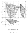
    • Fig. 1 shows a color gamut of the color CRT on the CIE standard L*u*v* colorimetric system,
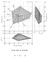
    • Fig. 2 shows a color gamut of a printing on the CIE standard L*u*v* colorimetric system,
    • Fig. 3 shows a glay wedge target patches,
    • Fig. 4 shows a target color on the Y-M coordinate system,
    • Fig. 5 is the L*u*v* colorimetric system converted from the Y-M coordinate system in Fig. 4,
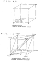
    • Fig. 6 shows the Y-M coordinate system,
    • Fig. 7 is the L*u*v* colorimetric system converted from the Y-M coordinate system in Fig. 6,
    • Figs. 8 to 13 are illustrations for the color estimation method of the present invention,
    • Fig. 14 shows hue angle on the L*u*v* colorimetric system,
    • Figs. 15 to 18 are illustrations for the interpolation processing, Figs. 19 and 20 are schematic views of a color masking device, and Figs. 21 and 22 are illustrations for the conventional method.
  • An embodiment of the present invention will be described hereunder with reference to the accompanying drawings. In this embodiment, combinations of image data of Y, M, C, and K (black) for reproducing reproduced colors by each combination of R, G, and B image data on the color CRT, for example, by color printing are obtained.
  • It is assumed that the values of R, G, B, Y, M, C, and K range from 0 to 255.
  • (1) Firstly, a color patch by each combination of R, G, and B image data is displayed on the color CRT device and measured colorimetrically, and the values of the XYZ colorimetric system are obtained and then the values of the L*u*v* colorimetric system are obtained.
  • In this case, for example, by using a device which writes R, G, and B image data into a frame memory of 8-bit R, G, and B, which is connected to the color CRT device, by a computer and displays the colors on the color CRT device, the values of the XYZ colorimetric system are obtained by Method 1 or Method 2 which will be described hereunder.
  • Method 1
  • Five quantization levels of 0, 64, 128, 192, and 255 are provided for each of R, G, and B image data, a computer is operated so that the colors of combinations of the levels (5 x 5 x 5 = 125) are displayed one by one on the color CRT device, each color is colorimetrically measured by a spectral radiometer, and the values of the XYZ colorimetric system are obtained.
  • The intermediate levels of the 5 x 5 x 5 = 125 color data are interpolated and the number of color data is increased to 9 x 9 x 9 = 729. The 729 colors may be measured colorimetrically, though the measurement count is so large.
  • Method 2
  • The values of the XYZ colorimetric system may be calculated by using the basic expression indicated below, which is well known as a color CRT color reproduction expression.
    Figure imgb0001
  • The coefficients XR, XG, XB, YR, YG, YB, ZR, ZG, ZB, and gamma are determined according to the characteristics of the CRT device used. 10 to 20 points are taken from the quantization levels 0 to 255 for each monochrome of R, G, and B, the colors, which are displayed on the color CRT device using the values, are measured colorimetrically by the spectral radiometer so as to obtain the X, Y, and Z values, and each coefficient is obtained from the relation between the R, G, and B values and the X, Y, and Z values.
  • By doing this, the values of the XYZ colorimetric system are obtained for each of the 9 x 9 x 9 = 729 colors by Method 1 or Method 2. The values of the L*u*V* colorimetric system are calculated from the values of the XYZ colorimetric system. The relation between x and y and X, Y, and Z is as follows: x = X / (X + Y + Z), y = Y / (X + Y + Z)
    Figure imgb0002
  • The values of x and y of D65 are x = 0.3127 and y = 0.3290. Therefore, Xn, Yn, and Zn satisfy the following expressions. Xn / (Xn + Yn + Zn) = 0.3127
    Figure imgb0003
    Yn / (Xn + Yn + Zn) = 0.3290
    Figure imgb0004
  • It is necessary to determine the levels of the absolute values of Xn, Yn, and Zn. To match the levels with the levels of the measured values of X, Y, and Z, the value of Yn is made nearly equal to the value of Y among X, Y, and Z when white (R = G = B = 255) is displayed.
  • By doing this, the values of the L*u*v* colorimetric system can be obtained for the 9 x 9 x 9 = 729 colors of R, G, and B image data. The L*u*v* colorimetric system values are defined as follows:
       L* TV1 (R, G, B)
       u* TV1 (R, G, B)
       v* TV1 (R, G, B)
  • Fig. 1 shows these values on the L*u*v* colorimetric system. Hereinafter, these values are called the CRT color gamut.
  • (2) Next, a color patch by each combination of Y, M, and C image data is measured colorimetrically, and the values of the XYZ colorimetric system are obtained and then the values of the L*u*v* colorimetric system are obtained.
  • In this case, five quantization levels of 0, 64, 128, 192, and 255 are provided for each of Y, M, and C image data, and color patches of each combination of the levels (5 x 5 x 5 = 125) are produced.
  • K image data is obtained from the following relation equation for each combination of Y, M, and C image data, and black K in the amount is added to the color patches of the Y, M, and C image data. K = 1.6 (min. [Y, M, C] - 128)
    Figure imgb0005
    where K = 0 when K < 0.
    Data is actually printed by the normal printing plate printing process that 4 images of Y, M, C, and k:
       Y (5 x 5 x 5)
       M (5 x 5 x 5)
       C (5 x 5 x 5)
       K (5 x 5 x 5)
    are outputted to 4 monochromatic films by a scanner, 4 printing plates of Y, M, C, and K are exposed through each films, and the printed matter of 5 x 5 x 5 = 125 color patches are printed.
  • The color patches are measured by a spectrophotometer, the values of the XYZ colorimetric system are determined, and the values of the L*u*v* colorimetric system are calculated.
  • The intermediate levels of the 5 x 5 x 5 = 125 color data are interpolated and the number of color data is increased to 9 x 9 x 9 = 729. The 729 colors may be printed and measured colorimetrically, though the measurement count is so large.
  • By doing this, the values of the L*u*v* colarimetric system are obtained for the 9 x 9 x 9 = 729 colors of Y, M, C, and K image data. The values of the L*u*v* colorimetric system are defined as:
       L* IN (Y, M, C)
       u* IN (Y, M, C)
       v* IN (Y, M, C)
  • Fig. 2 shows these values on the L*u*v* colorimetric system. Hereinafter, these values are called the printed matter color gamut.
  • (3) Next, the maximum and minimum values of L* are obtained from the color CRT color gamut.
  • In this case, a combination wherein the value of L* is maximum among the 9 x 9 x 9 = 729 colors and a combination wherein the value of L* is minimum are obtained and the value of L* at that time is obtained.
  • [Maximum value]
  • The value of L* when white is displayed under the condition of R = G = B = 255 is defined as L* TV1max.
  • [Minimum value]
  • The value of L* when black is displayed under the condition of R = G = B = 0 is defined as L* TV1min.
  • (4) Next, the maximum and minimum values of L* are obtained from the printed matter color gamut.
  • In this case, a combination wherein the value of L* is maximum among the 9 x 9 x 9 = 729 colors and a combination wherein the value of L* is minimum are obtained and the value of L* at that time is obtained.
  • [Maximum value]
  • The L* value of white background on paper stork under the condition of Y = M = C = 0 (K = 0) is defined a L*INmax.
  • [Minimum value]
  • The value of L* when black is printed under the condition of Y = M = C = 255 (K = 203) is defined as L*INmin.
  • (5) Next, each value of the color CRT color gamut values L* TV1, u* TV1, and v* TV1 are converted to L* TV2, u* TV2, and v* TV2.
  • L* is converted linearly by the following expression so that the maximum and minimum values of L* of the color CRT color gamut are equal to the maximum and minimum values of L* of the printed matter color gamut.
    Figure imgb0006
  • u* and v* are converted by the following expressions in the same way. u* TV2 = L* TV2 L* TV1 u* TV1
    Figure imgb0007
    v* TV2 = L* TV2 L* TV1 v* TV1
    Figure imgb0008
  • (6) Next, a printed matter of a gray wedge target wherein the values of L* are at even intervals is provided.
  • A gray wedge target wherein u* and v* are 0 and L* ranges from 20 to 100 at intervals of five quantization levels is provided (see Fig. 3).
  • In this case, using the values of L* IN(Y, M, C), u* IN(Y, M, C), and v* IN(Y, M, C) of the printed matter color gamut, the values of Y, M, and C at each step of the wedge target chart are obtained by the convergence operation.
  • Next, the convergence operation will be described. The color gamut value at each step of the gray wedge target is given in the printed matter color gamut (shown in Fig. 2) as a target value T′.
  • For simplicity, two basic colors (for example, Y and M) are used for description.
  • Fig. 4 shows the Y-M coordinate system. When each lattice point is mapped on the L*u*v* colorimetric system by the process described in (2), Fig. 5 is obtained. The apexes B, C, G, and F of the square shown in Fig. 4 correspond to B′, C′, G′, and F′ shown in Fig. 5.
  • Firstly, a value of the color gamut on the L*u*v* colorimetric system, obtained by target patches of the combinations of Y and M is given as a target value T′ (see Fig. 5).
  • When the target value T′ is in the area enclosed by the lattice points a′, b′, c′, and d′ as shown in Fig. 5, it is inferred that the combination (target value T) of Y and M on the Y-M coordinate system is in the area enclosed by the lattice points a, b, c, and d as shown in Fig. 4.
  • The location of the target value T in the area formed by the lattice points a, b, c, and d is obtained by the convergence operation by mapping the colorimetric system shown in Fig. 5 onto the coordinate system shown in Fig. 4. The reason for performing the convergence operation is that the conversion from the coordinate system shown in Fig. 4 to the colorimetric system shown in Fig. 5 is well known, though the reverse conversion is complicated and a satisfactory conversion expression is not known.
  • Firstly, the area where the target value T' is located is obtained among a plurality of areas formed by 81 lattice points (see Fig. 5). When the target value T′ is in the area S0′ as shown in Fig. 7, it is inferred that the target value T is in the area S0 which corresponds to the area S0′ as shown in Fig. 6.
  • Next, the inferred area S0 is equally divided into 4 areas S1, S2, S3, and S4. Five division points, e to i, are calculated by weight average using the peripheral lattice points which are already obtained. The values corresponding to the division points, e to i, are converted to those on the L*u*v* colorimetric system, the converted values are plotted on the colorimetric system shown in Fig. 7, and the area among the four areas S1′, S2′, S3′, and S4′ formed by the plotted division points, e′ to i′, where the target value T′ exists, is obtained. When the target value T′ is in the area S2′ as shown in Fig. 7, it is inferred that the target value T is in the area S2 corresponding to the area S2′ as shown in Fig. 6.
  • Next, the inferred area S2 is equally divided into 4 areas S5, S6, S7, and S8. Five division points, j to n, are calculated by weight average using the peripheral lattice points, which are already obtained, and the division points. The values corresponding to the division points, j to n, are converted to those on the L*u*v* colorimetric system, the converted values are plotted on the colorimetric system shown in Fig. 7, and the area among the four areas S5′, S6′, S7′, and S8′ formed by the plotted division points, j′ to n′, where the target value T′ exists, is obtained. When the target value T′ is in the area S8′ as shown in Fig. 7, it is inferred that the target value T is in the area S8 corresponding to the area S8′ as shown in Fig. 6.
  • Next, the inferred area S8 is equally divided into 4 areas S9, S10, S11, and S12. Five division points, o to s, are calculated by weight average using the peripheral lattice points, which are already obtained, and the division points. The values corresponding to the division points, o to s, are converted to those on the L*u*v* colorimetric system, converted values are plotted on the colorimetric system shown in Fig. 7, and the area among the four areas S9′, S10′, S11′, and S12′ formed by the plotted division points o′ to s′, where the target value T′ exists, is obtained. When the target value T′ is in the area S10′ as shown in Fig. 7, it is inferred that the target value T is in the area S10 corresponding to the area S10′ as shown in Fig. 6.
  • As the areas are divided repeatedly like this, the lattice becomes small gradually and is converged finally. By averaging the four lattice points forming the converged area or the division points, the target value T can be obtained.
  • For the values of Y, M, and C at each step, which are obtained by the above convergence operation, the value of K is obtained from the expression (1).
  • Images are printed from the image data of Y, M, C, and K at each step, which are obtained as described above, wedge target printing process, and a gray wedge target is produced.
  • (7) Next, a wedge target chart wherein the values of L* are at even intervals is displayed on the color CRT device.
  • A gray wedge target wherein u* and v* are 0 and L* ranges from 20 to 100 at intervals of five quantization levels is displayed (see Fig. 3).
  • In this case, using L* TV2(R, G, B), u* TV2(R, G, B), and v* TV2(R, G, B) as color gamut data, the values of R, G, and B at each step of the gray wedge target are obtained by the convergence operation.
  • A gray wedge target is displayed on the color CRT device from the image data of R, G, and B at each step, which are obtained as described above.
  • (8) Next, the wedge target chart on the color CRT device is compared with the gray wedge target of the printed matter, and whether the condition of discrimination on the boundary at each step of the target on the color CRT device is the same as that of the target of the printed matter is checked. When they are not the same, the values of the L*u*v* colorimetric system of the color gamut on the color CRT device are converted as follows:
    Figure imgb0009
    u* TV3 = L* TV3 L* TV2 u* TV2
    Figure imgb0010
    v* TV3 = L* TV3 L* TV2 v* TV2
    Figure imgb0011
  • The value of the constant r is changed, L* TV3, u* TV3, and v* TV3 are recalculated, the operation in (7) is performed by using L* TV3, u* TV3, and v* TV3 instead of L* TV2, u* TV2, and v* TV2, and the target on the CRT device is compared with the target of the printed matter once again.
  • The operations in (7) and (8) are repeated, and L* TV3, u* TV3, and v* TV3 can realized good reproduction matched to printing matter, are used in the following operation.
  • (9) Next, a combination of Y, M, C, and K (color correction data) for each combination of R, G, and B is obtained.
  • The values L* TV3, u* TV3, and v* TV3 of the L*u*v* colorimetric system for the color (32 x 32 x 32 = 32768) of each combination of R, G, and B are obtained. The values are given to the color gamut of the printed matter (shown in Fig. 2) as a target value T′, and the values of Y, M, and C for each combination of R, G, and B are obtained by the convergence operation.
  • Since the color reproduction gamut of the printed matter is narrower than the color reproduction gamut of the color CRT on this stage, the target value T′ may be outside the color reproduction gamut of the printed matter. The target value T′ is converted to a value within the color reproduction gamut of the printed matter by one of the following methods in Example 1 to Example 5, and then the values of Y, M, and C are obtained by the convergence operation.
  • Example 1
  • The values L* TV3, u* TV3, and v* TV3, which are obtained for each combination of R, G, and B, are given to the printed matter color gamut (shown in Fig. 2) as a target value T˝. The values of L*, u*, and v* at this time are assumed as L* T˝, u* T˝, and v* T˝. Assuming that the chroma value obtained by u* T˝² + v* T˝²
    Figure imgb0012
    is rT˝ and the hue angle obtained by arctan (v* T˝ / u* T˝) is ϑT′, the chroma value r INmidT˝ which is "a" (a < 1.0) times, for example, about 2/3 times, of the maximum chroma value r INmaxT˝ of the color gamut of the printed matter for L* T˝ and ϑT˝ is taken as a threshold value (see Fig. 8).
  • When rT˝ is smaller than r INmidT˝, no correction is performed, and it is assumed that L* T′ = L* T˝, u* T′ = u* T˝, v* T′ = v* T˝, rT′ = rT˝, and ϑT′ = ϑT˝.
  • When rT˝ is larger than r INmidT˝, it is assumed that L* T′ = L* T˝ and ϑT′ = ϑT˝ and rT′ is expressed as follows: rT′ = (r INmaxT˝ - r INmidT˝) (r TVmaxT˝ - r INmidT˝) × (rT˝ - r INmidT˝) + r INmidT˝
    Figure imgb0013
  • In this expression, r TVmaxT˝ is the maximum chroma value of the color gamut on the color CRT device for L* T˝ and ϑT˝ (see Fig. 8).
  • u* T′ and v* T′ are so determined that ϑT′ = ϑT˝ and that rT′ satisfies the above expression.
  • As described above, L* T′, u* T′, and v* T′ which are converted from L* T˝, u* T˝, and v* T˝ are within the color reproduction scope of the printed matter.
  • The maximum chroma value is obtained as specified below.
  • Values wherein only values of combinations for the outer surface of the color gamut are converted to lightness L*, chroma r, and hue ϑ are used. There are 8 surfaces which constitute the outer surface of the color gamut, where the values of Y, M, and C or R, G, and B are all 0 or maximum. The location of the maximum chroma value in the lattice containing the hue ϑ and lightness L* is searched for, and the maximum chroma value is obtained from the chroma values at 4 peripheral points by weight average.
  • Example 2
  • In this example, a straight line passing L*T˝ and rT˝ on a section of the color gamut at a hue angle of ϑT˝ is considered (see Fig. 9). The straight line is expressed as shown below. In this expression, a symbol r indicates a chroma. L* = b x r + c
    Figure imgb0014
  • By the movement distance which is obtained from the maximum chroma value of the color gamut of the printed matter on the straight line, the chroma value which is 2/3 times of the maximum chroma value, and the maximum chroma value of the color gamut on the color CRT device, the target value moves inward on the straight line.
  • The meaning of the above straight line is that since the target value moves on the straight line, the rate at which the lightness is decreased or increased so as to decrease the chroma is determined.
  • Expression 2 is determined as follows depending on the value of L* T˝:
    When L* T˝ ≦ 70:
       b = 0
       c = L* T˝
    Hence:
    Figure imgb0015
    When L* T˝ > 70:
       b = (L* 0 - 70) / 30 x 0.15
       c = L* 0
    Hence:
    Figure imgb0016
  • L* 0 indicates a value of L* when r = 0 and is obtained, for example, as shown below by using L* T˝ and rT˝ for L* and r in Expression 2: L* 0 = L* T˝ + 0.15 x 70 x rT˝ / 30 1 + 0.15 x rT˝ / 30
    Figure imgb0017
  • Fig. 10 shows status changes of the straight line which is determined as described above.
  • Next, the chroma is converted on the straight line which is determined by the target value T˝ like this.
  • As shown in Fig. 11, the chroma value r INmidT˝ which is "a" times (a < 1.0), for example, about 2/3 times of the maximum chroma value r INmaxT˝ of the color gamut of the printed matter on the straight line is assumed as a threshold value.
  • When rT˝ is smaller than r INmidT˝, no correction is performed, and it is assumed that L* T′ = L* T˝, u* T′ = u* T˝, v* T′ = v* T˝, rT′ = rT˝, and ϑT′ = ϑT˝.
  • When rT˝ is larger than r INmidT˝, it is assumed that the maximum chroma value of the color gamut of color CRT on the straight line is r TVmaxT˝ and rT′ is obtained as follows: rT′ = (r INmaxT˝ - r INmidT˝) (r TVmaxT˝ - r INmidT˝) × (rT˝ - r INmidT˝) + r INmidT˝
    Figure imgb0018
  • It is assumed that the hue angle is fixed and ϑT′ = ϑT˝. u* T′ and v* T′ are values when ϑT′ = ϑT˝ and rT′ satisfies the above expression.
  • Furthermore, since the variation of lightness when the chroma value moves from rT˝ to rT′ on the straight line is b (rT˝ - rT′), it is assumed that: L* T′ = L* T˝ - b (rT˝ - rT′)
    Figure imgb0019
  • In this case, when L* T˝ ≦ 70, b = 0 and the lightness does not change. When L* T˝ > 70, b > 0 and the lightness decreases.
  • As described above, L* T′, u* T′, and v* T′ which are converted from L* T˝, u* T˝, and v* T˝ are within the color reproduction scope of the printed matter.
  • Example 1 is equivalent to Example 2 wherein L* of the expression of the straight line, Expression 2, is fixed to L* T˝. Fig. 12 shows status changes of the straight line in Example 1.
  • Example 3
  • Also in this example, the straight line expressed by Expression (2) is assumed in the same way as with Example 2. In this example, Expression (2) is determined as shown below depending on the value of L* T˝:
    When L* T˝ < 50:
       b = (50 - L* 0) / 30 x (-0.15)
       c = L* 0
    Hence:
    Figure imgb0020
    When 50 ≦ L* T˝ ≦ 70:
       b = 0
       c = L*
    Hence: L* = L* T˝
    Figure imgb0021
    When L* T˝ > 70:
       b = (L* 0 - 70) / 30 x 0.15
       c = L* 0
    Hence:
    Figure imgb0022
  • Fig. 13 shows status changes of the straight line which is determined as described above.
  • Next, the chroma r is converted on the straight line which is determined by the target value T˝ like this.
  • As shown in Fig. 11, the chroma value r INmidT˝ which is "a" times (a < 1.0), for example, about 2/3 times of the maximum chroma value r INmaxT˝ of the color gamut of the printed matter on the straight line is assumed as a threshold value.
  • When rT˝ is smaller than r INmidT˝, no correction is performed, and it is assumed that L* T′ = L* T˝, u* T′ = u* T˝, v* T′ = v* T˝, rT′ = rT˝, and ϑT′ = ϑT˝.
  • When rT˝ is larger than r INmidT˝, it is assumed that the maximum chroma value of the color gamut of color CRT on the straight line is r TVmaxT˝ and rT′ is obtained as follows: rT′ = (r INmaxT˝ - r INmidT˝) (r TVmaxT˝ - r INmidT˝) × (rT˝ - r INmidT˝) + r INmidT˝
    Figure imgb0023
  • It is assumed that the hue angle is fixed and ϑT′ = ϑT˝. u* T′ and v* T′ are values when ϑT′ = ϑT˝ and rT′ satisfies the above expression.
  • Furthermore, since the variation of lightness when the chroma value moves from rT˝ to rT′ on the straight line is b (rT˝ - rT′), it is assumed that: L* T′ = L* T˝ - b (rT˝ - rT′)
    Figure imgb0024
  • In this case, when L* T˝ < 50, b < 0 and the lightness increases. When 50 ≦ L* T˝ ≦ 70, b = 0 and the lightness does not change. When L* T˝ > 70, b > 0 and the lightness decreases.
  • As described above, L* T′, u* T′, and v* T′ which are converted from L* T˝, u* T˝, and v* T˝ are within the color reproduction scope of the printed matter.
  • Example 4
  • In this example as shown in Fig. 8, in the same way as with Example 1, the chroma value r INmidT˝ which is about 2/3 times of the maximum chroma value r INmaxT˝ of the color gamut of the printed matter is assumed as a threshold value.
  • When rT˝ is smaller than r INmidT˝, no correction is performed, and it is assumed that L* T′ = L* T˝, u* T′ = u* T˝, v* T′ = v* T˝, rT′ = rT˝, and ϑT′ = ϑT˝.
  • When rT˝ is larger than r INmidT˝, rT′ is set as shown below depending on ϑT˝.
  • If the expression "120° ≦ ϑT˝ ≦ 170°" is not held when the hue angle ϑ is set as follows (see Fig. 14):
       ϑ = 0°: Positive on the u* axis
       ϑ = 90°: Positive on the v* axis
       ϑ = 180°: Negative on the u* axis
       ϑ = 270°: Negative on the v* axis
       ϑ = 360°: Positive on the u* axis
    it is required that L* T′ = L* T˝ and ϑT′ = ϑT˝ and rT′ is expressed as follows: rT′ = (r INmaxT˝ - r INmidT˝) (r TVmaxT˝ - r INmidT˝) × (rT˝ - r INmidT˝) + r INmidT˝
    Figure imgb0025
  • In this expression, r TVmaxT˝ is the maximum chroma value of the color gamut on the color CRT device for L* TV3 and ϑT˝ (see Fig. 8).
  • u* T′ and v* T′ are values when ϑT′ = ϑT˝ and rT′ satisfies the above expression.
  • Next, when the expression "120° ≦ ϑT˝ ≦ 170°" is held, ϑT˝ is converted to ϑT˝ 2 by the following expression.
  • 131° is a hue angle at the maximum chroma point of G (green) of the color gamut of color CRT (see Fig. 1), and 147° is a hue angle at the maximum chroma point of G (green) of the color gamut of the printed matter (see Fig. 2).
    When 120° ≦ ϑT˝ ≦ 131°: ϑT˝ 2 = (147° - 131°) (r INmaxT˝ - r INmidT˝) (r TVmaxT˝ - r INmidT˝) × (rT˝ - r INmidT˝) x (ϑT˝ - 120°) (131° - 120°) + ϑT˝
    Figure imgb0026
    When 131° < ϑT˝ ≦ 170°: ϑT˝ 2 = (147° - 131°) (r INmaxT˝ - r INmidT˝) (r TVmaxT˝ - r INmidT˝) × (rT˝ - r INmidT˝) x (170° - ϑT˝) (170° - 131°) + ϑT˝
    Figure imgb0027
  • Therefore, it is required that L* T′ = L* T˝ and ϑT′ = ϑT˝ 2 and rT′ is expressed as follows: rT′ = (r INmaxT˝ 2 - r INmidT˝ 2) (r TVmaxT˝ 2 - r INmidT˝ 2) × (rT˝ - r INmidT˝ 2) + r INmidT˝ 2
    Figure imgb0028
  • In this expression, r INmaxT˝ 2 indicates the maximum chroma value of the color gamut of the printed matter for L* T˝ and ϑT˝ 2, r INmidT˝ 2 indicates a chroma value which is "a" times of r INmaxT˝ 2, and r TVmaxT˝ 2 indicates the maximum chroma value of the color gamut of color CRT for L* T˝ and ϑT˝ 2.
  • u* and v* are values when ϑT′ = ϑT˝ 2 and rT′ satisfies the above expression.
  • As described above, L* T′, u* T′, and v* T′ which are converted from L* T˝, u* T˝, and v* T˝ are within the color reproduction gamut of the printed matter.
  • The maximum chroma value can be obtained in the same as with Example 1.
  • Example 5
  • In this example, in the same way as with Example 1 or Example 4, the chroma value r INmidT˝ which is about 2/3 times of the maximum chroma value r INmaxT˝ of the color gamut of the printed matter is assumed as a threshold value.
  • When rT˝ is smaller than r INmidT˝, no correction is performed, and it is assumed that L* T′ = L* T˝, u* T′ = u* T˝, v* T′ = v* T˝, rT′ = rT˝, and ϑT′ = ϑT˝.
  • When rT˝ is larger than r INmidT˝, rT′ is set as shown below depending on ϑT˝.
  • When the expression "200° ≦ ϑT˝ ≦ 300°" is not held, it is required that L* T′ = L* T˝ and OT′ = OT˝ and rT′ is expressed as follows: rT′ = (r INmaxT˝ - r INmidT˝) (r TVmaxT˝ - r INmidT˝) × (rT˝ - r INmidT˝) + r INmidT˝
    Figure imgb0029
  • In this expression, r TVmaxT˝ is the maximum chroma value of the color gamut on the color CRT device for L* TV3 and OT˝ (see Fig. 8).
  • u* T′ and v* T′ are values when ϑT′ = ϑT˝ and rT′ satisfies the above expression.
  • Next, when the expression "200° ≦ ϑT˝ ≦ 300°" is held, ϑT˝ is converted to ϑT˝ 2 by the following expression.
  • 266° is a hue angle at the maximum chroma point of B (blue) of the color gamut of the color CRT (see Fig. 1), and 234° is a hue angle at the maximum chroma point of C (cyan) of the color gamut of the printed matter (see Fig. 2).
    When 266° ≦ ϑT˝ ≦ 300°: ϑT˝ 2 = (234° - 266°) (r INmaxT˝ - r INmidT˝) (r TVmaxT˝ - r INmidT˝) × (rT˝ - r INmidT˝) x (300° - ϑT˝) (300° - 266°) + ϑT˝
    Figure imgb0030
    When 200° ≦ ϑT˝ < 266°: ϑT˝ 2 = (234° - 266°) (r INmaxT˝ - r INmidT˝) (r TVmaxT˝ - r INmidT˝) × (rT˝ - r INmidT˝) x (ϑT˝ - 200°) (266° - 200°) + ϑT˝
    Figure imgb0031
  • Therefore, it is required that L* T′ = L* T˝ and ϑT′ = ϑT˝ 2 and rT′ is expressed as follows: rT′ = (r INmaxT˝ 2 - r INmidT˝ 2) (r TVmaxT˝ 2 - r INmidT˝ 2) × (rT˝ - r INmidT˝ 2) + r INmidT˝ 2
    Figure imgb0032
  • In this expression, r INmaxT˝ 2 indicates the maximum chroma value of the color gamut of the printed matter for L* T˝ and ϑT˝ 2, r INmidT˝ 2 indicates a chroma value which is "a" times of r INmaxT˝ 2, and r TVmaxT˝ 2 indicates the maximum chroma value of the color gamut of the color CRT for L* T˝ and ϑT˝ 2.
  • u* and v* are values when ϑT′ = ϑT˝ 2 and rT′ satisfies the above expression.
  • As described above, L* T′, u* T′, and v* T′ which are converted from L* T˝, u* T˝, and v* T˝ are within the color reproduction gamut of the printed matter.
  • Next, the values L* T′, u* T′, and v* T′, which are obtained for each combination of R, G, and B, are given to the printed matter color gamut (shown in Fig. 2) as a target value T′, and the values of Y, M, and C are obtained by the convergence operation. Since the convergence operation is the same as the one described in Figs. 4 to 7, the description is omitted.
  • For each combination of Y, M, and C for each combination of R, G, and B which are obtained in Example 1 to Example 5 like this, the value of K is obtained from Expression (1).
  • By doing this, combinations of Y, M, C, and K for reproducing reproduced colors by each combination of R, G, and B, for example, by color printing are obtained.
  • In this example, as described above, as to the lightness direction, L* among the values of the colorimetric system obtained for each combination of R, G, and B is converted according to the ratio of the lightness range of the color gamut of the color CRT (input side) on the lightness axis to that of the color gamut of the printed matter (output side), and the lightness of the color gamut of the color CRT is compressed and mapped. As to the chroma direction, no value is corrected at the overlapped center portion of the color gamut of the color CRT (input) and that of the color gamut of the printed matter (output). In the peripheral area, u* and v* among the values of the colorimetric system obtained for each combination of R, G, and B are converted according to the chroma range of the two color gamuts and the chroma of the color gamut of color CRT is compressed and mapped.
  • By doing this, the color reproduction gamut of color CRT is included in the color reproduction gamut of the printed matter by a natural conversion result, and the color reproduction obtained by a combination of Y, M, C, and K provides satisfactory and natural lightness and chroma.
  • In this example, for example, in a high or low lightness area, the slope of the straight line is positive or negative and the decrease amount of chroma is suppressed when the chroma is compressed and mapped, and hence decreases in color saturation caused by compression and mapping in the high lightness and chroma area or in the low lightness and chroma area can be prevented.
  • When the chroma of the color gamut of the color CRT is compressed and mapped, the hue is moved in the direction from the G (green) peak of the color gamut of the color CRT to the G peak of the color gamut of the printed matter or from the B (blue) peak of the color gamut of the color CRT to the C (cyan) peak of the color gamut of the printed matter, and hence the chroma is balanced as a whole.
  • In Example 5 of the above embodiment, the hue is moved in the direction from the B (blue) peak of the color gamut of the color CRT to the C (cyan) peak of the color gamut of the printed matter. The hue may be moved to the M (magenta) peak in the reverse direction.
  • In Example 4 or Example 5 of the above embodiment, the hue range where the hue is moved is limited to one area. A plurality of areas may be used, and Example 4 and Example 5 may be used simultaneously.
  • In the above embodiment, the lightness is kept constant when the chroma is moved. The lightness may be changed as the chroma moves.
  • In the above embodiment, the CIE standard L*u*v* colorimetric system is used as a colorimetric system. The CIE standard L*a*b* colorimetric system may be used.
  • Next, a color masking device, which is constructed so that the color correction data (Y, M, C, and K) obtained as described above is stored in a look up table (LUT) beforehand and the color correction data is referred to by input image data (R, G, B), will be described.
  • In this case, when Y, M, C, and K image data corresponding to all R, G, and B image data is to be stored in the lookup table, a large capacity is required for the lookup table.
  • The applicant proposes a method that to reduce the memory capacity, a color space formed by R, G, and B image data is divided into a plurality of basic lattices, Y, M, C, and K image data for a combination of R, G, and B image data positioned at the apexes thereof are stored in the lookup table, and when Y, M, C, and K image data for a combination of R, G, and B image data do not exist, Y, M, C, and K image data are obtained by weight average of the Y, M, C, and K image data at the apexes of the basic lattices containing the R, G, and B image data (interpolation point).
  • As shown in Fig. 15, for example, when an interpolation point P exists in a basic lattice formed by the apexes A to H, the volume of each cuboid formed by the apexes which are diagonally positioned to the interpolation point P and point P itself is used as a weighting factor for the Y, M, C, and K image data at the apexes A to H.
  • Assuming that the Y, M, C, and K image data at the apexes A to H of the basic lattice containing the interpolation point P are Yi, Mi, Ci, and Ki (i = 1 to 8) and the weighting factor for the Y, M, C, and K image data at the apexes A to H is Ai (i = 1 to 8), Y, M, C, and K image data Yp, Mp, Cp, and Kp at the interpolation point P are calculated from the following expressions.
    Figure imgb0033
  • In this interpolation process, calculation of Y, M, C, and K image data Yp, Mp, Cp, and Kp at the interpolation point P requires 8 times of multiplication accumulation processing for each data.
  • The applicant proposes interpolation process which minimizes the multiplication accumulation process count.
  • For a basic lattice formed by the apexes A to H, as shown in Fig. 16, six triangular pyramids enclosed by dashed lines are formed. When the coordinates of an interpolation point P are (5, 1, 2), the interpolation point P is contained in a triangular pyramid T formed by the apexes A, B, C and G as shown in Fig. 17.
  • When the triangular pyramid T is determined, the interpolation point P is connected to the apexes A, B, C, and G, new 4 triangular pyramids are formed, and the volumes VBCGP, VACGP, VABGP, and VABCP can be obtained. The Y, M, C, and K image data Yp, Mp, Cp, and Kp at the interpolation point P are calculated from the volumes and the Y, M, C, and K image data YA to YG, MA to MG, CA to CG, and KA to KG at the apexes A, B, C, and G using the following expressions:
  • VABCG indicates the volume of the triangular pyramid T.
    Figure imgb0034
  • When the coordinates of the interpolation point P are changed, the triangular pyramid T to be used is changed. When the coordinates of the interpolation point P are P(3, 1, 5), for example, the interpolation point P is contained in a triangular pyramid T formed by the apexes A, C, D, and G as shown in Fig. 18 and this triangular pyramid is used.
  • In the interpolation processing using a triangular pyramid like this, the Y, M, C, and K image data Yp, Mp, Cp, and Kp at the interpolation point P can be calculated by 4 times of multiplication accumulation processing.
  • Fig. 19 shows an actual configuration example of a color masking device.
  • In Fig. 19, numeral 20 indicates a color correction data storage means, and lookup tables (MLUT) 21Y to 21K constituting the storage means 20 store Y, M, C, and K color correction data.
  • ROMs, for example, with a capacity of 256K bits are used for MLUT21Y to MLUT21K, only 32 points between the minimum level and the maximum level of R, G, and B image data are extracted, and image data at 32 x 32 x 32 = 32768 points are stored in each of MLUT21Y to MLUT21K.
  • In this case, R, G, and B image data are 8 bits long and have 256 gradations. As to distribution of 32 points, 256 is evenly divided into 32 portions by 8 sequentially, for example, starting at 0 as follows:
       0, 8, 16, ---, 240, 248
  • The numbers from 249, which is the 33rd point, to 255 are not used or handled as 248.
  • The Y, M, C, and K image data at the distribution points, that is, at the apexes of the basic lattice whose basic lattice interval is the 8-quantization level are calculated as described above, and the calculated image data are stored in MLUT21Y to MLUT21K.
  • Numeral 60 indicates a lookup table (WLUT) constituting a weighting factor storage means. WLUT60 stores the weighting factor corresponding to each interpolation point.
  • In the case of the interpolation process using a cube, when the basic lattice interval is the 8-quantization level as described above, the total of 8 times of weighting factors is: 8 x 8 x 8 = 512
    Figure imgb0035
  • Which is normalized so that the total is 256 revel. The maximum weighting factor is 255 so that a 8-bit general purpose IC can be used as WLUT60. When the interpolation point P is, for example, at a position which is the same as the apex A shown in Fig. 15, the weighting factors P1 to P8 are as follows:
    Figure imgb0036
  • The total of weighting factors is always 256.
  • In the case of the interpolation process using a triangular pyramid, when the basic lattice interval is the 8-quantization level as described above, the total of 4 times of weighting factors is: 8 x 8 x 8 / 6 = 512 /6
    Figure imgb0037
  • Which is normalized so that the total is 256.
  • The maximum weighting factor is 255 so that a 8-bit general purpose IC can be used as WLUT60. When the interpolation point P is, for example, at a position which is the same as the apex A shown in Fig. 16, the weighting factors VBCGP, VACGP, VABGP, and VABCP are as follows:
    Figure imgb0038
  • The total of weighting factors is always 256.
  • R, G, and B image data are supplied to lookup tables (PLUT) 41R to 41B constituting an address signal generation means 40, and distribution signals are supplied to PLUT41R to PLUT41B from a controller 50.
  • 5-bit address signals corresponding to the upper 5 bits (indicating the reference points at the apexes of the basic lattice containing the interpolation point P) of R, G, and B image data are outputted from PLUT41R to PLUT41B and supplied to MLUT21Y to MLUT21K.
  • In the case of the interpolation process using a cube, 5-bit address signals are outputted sequentially according to distribution signals so that the 8 apexes of the basic lattice containing the interpolation point P are specified sequentially by MLUT21Y to MLUT21K.
  • In the case of the interpolation process using a triangular pyramid, 5-bit address signals are outputted sequentially according to distribution signals so that the 4 apexes of the triangular pyramid containing the interpolation point P are specified sequentially by MLUT21Y to MLUT21K.
  • Y, M, C, and K image data outputted from MLUT21Y to MLUT21K are supplied to multipliers (MTL) 31Y to 31K constituting a multiplication accumulation means 30.
  • Lower 3 bits (indicating the position of the interpolation point P in the basic lattice) of R, G, and B image data are outputted from PLUT41R to PLUT41B as weighting factor specification signals, and the weighting factor specification signals are supplied to WLUT60. Distribution signals are supplied to WLUT60 from the controller 50, and the weighting factors are sequentially outputted according to the distribution signals.
  • In the case of the interpolation process using a cube, as the 8 apexes of the basic lattice containing the interpolation point P are specified sequentially by MLUT21Y to MLUT21K, the 8 weighting factors P1 to P8 are sequentially outputted.
  • In the case of the interpolation process using a triangular pyramid, as the 4 apexes of the triangular pyramid containing the interpolation point P are specified sequentially by MLUT21Y to MLUT21K, the 4 weighting factors are sequentially outputted.
  • Weighting factors outputted from WLUT60 are supplied to MTL31Y to MTL31K. Y, M, C, and K image data (8 bits long) outputted from MLUT21Y to MLUT21K are multiplied by weighting factors (8 bits long) from WLUT60 in MTL31Y to MTL31K.
  • Multiplication outputs of upper 8 bits of MTL31Y to MTL31K are supplied to accumulators (ALU) 32Y to 32K and added by them. A reset signal is supplied to ALU32Y to ALU32K from the controller 50.
  • In the case of the interpolation process using a cube, in correspondence with the 8 apexes of the basic lattice containing the interpolation point P, the add operation is performed sequentially. Whenever the results are latched by a latch circuit which will be described later, the accumulators are reset.
  • In the case of the interpolation process using a triangular pyramid, in correspondence with the 4 apexes of the triangular pyramid containing the interpolation point P, the add operation is performed sequentially. Whenever the results are latched by a latch circuit which will be described later, the accumulators are reset.
  • As described above, the total of 8 weighting factors in the case of the interpolation processing using a cube and the total of 4 weighting factors in the case of the interpolation process using a triangular pyramid are 256. In this example, the upper 8 bits of multiplication outputs of MTL31y to MTL31K are used, that is, a so-called 8-bit shift is performed. By doing this, the processing of
    Figure imgb0039
    in Expression (3) and 1/V ABCG in Expression (4) is performed.
  • Outputs of ALU32Y to ALU32K constituting the multiplication accumulation means 30 are supplied to latch circuits 71Y to 71K. A latch pulse is supplied to the latch circuits 71Y to 71k from the controller 50.
  • In the case of the interpolation process using a cube, the results of the add operation which is performed sequentially in correspondence with the 8 apexes of the basic lattice containing the interpolation point P are latched.
  • In the case of the interpolation process using a triangular pyramid, the results of the add operation which is performed sequentially in correspondence with the 4 apexes of the triangular pyramid containing the interpolation point P are latched.
  • Therefore, in the case of the interpolation processing using a cube, Y, M, C, and K image data expressed by Expression (3), at the interpolation point P are outputted from the latch circuits 71Y to 71K. In the case of the interpolation process using a triangular pyramid, Y, M, C, and K image data expressed by Expression (4), at the interpolation point P are outputted from the latch circuits 71Y to 71K.
  • Fig. 20 shows an example that behind a color masking device (A in the drawing) for outputting Y, M, and C image data without K image data being stored in the lookup table beforehand, a device (B in the drawing), which obtains K image data from Expression (1) and outputs it, is added. In this example, the memory capacity can be decreased. The parts shown in Fig. 20 which correspond to those shown in Fig. 19 are assigned with the same numbers and the detailed description is omitted.
  • In Fig. 20, Y, M, and C image data outputted from the latch circuits 71Y to 71C are supplied to a minimum value detection circuit 81, and the minimum value among Y, M, and C, that is, min[Y, M, C] is detected. Detected min[Y, M, C] is supplied to a lookup table 82, and the lookup table 82 outputs K image data which is obtained from the following relational expression. K = 1.6 x (min [Y, M, C] - 128)
    Figure imgb0040
    where, when K < 0, K = 0.
  • According to the present invention, as described above, as to the lightness direction, L* among the values of the colorimetric system obtained for each combination of the input color component image information is converted according to the ratio of the lightness range of the input side color gamut on the lightness axis to that of the output side color gamut, and the lightness of the input side color gamut is compressed and mapped. As to the chroma direction, no value is corrected at the overlapped center portion of the color reproduction gamut of the input side and that of the output side. In the peripheral area, u* and v* or a* and b* among the values of the colorimetric system obtained for each combination of the input color component image information are converted according to the chroma range of the two color gamuts and the chroma of the input side color gamut is compressed and mapped.
  • Therefore, the color reproduction gamut of the input side is included in the color reproduction gamut of the output side by a natural conversion result, and the color reproduction obtained by the output color component image information becomes natural.
  • When u* and v* or a* and b* are converted, for example, in a high lightness area and the chroma is compressed and mapped, the decrease amount of chroma is suppressed. Therefore, decreases in color saturation by compression and mapping, for example, in a high lightness or chroma area can be surpressed.
  • When the chroma of the input side color gamut is compressed and mapped, the hue is moved so that the peak of each color of the input side color gamut moves toward the peak of the corresponding color of the output side color gamut. Therefore, the color reproduction gamut on the input side is included in the color reproduction gamut on the output side by natural conversion with the entire chroma balance kept, the color reproduction obtained by the output color component image information provides satisfactory lightness and chroma, and the chroma is well balanced as a whole.

Claims (6)

  1. A method for transforming color image data of first media so as to be reproduced by second media, the color reproducing capability of which is smaller than that of the first media, comprising:
       obtaining a first colour range or gamut on a colourimetric system on the basis of a plurality of color image data of the first media beforehand, the colorimetric system being one of the CIE standard L*u*v* and L*a*b* color systems;
       obtaining a second colour range or gamut on the colourimetric system on the basis of a plurality of color image data of the second media beforehand;
       calculating the first lightness difference between the maximum and minimum values of the lightness on the lightness axis of the first color gamut, the second lightness difference between them of the seond color gamut, and the lightness defference ratio between the first and second lightness differences in advance;
       inputting image data of the first media;
       converting the L* value of a color image data "T" of the first media on the basis of the lightness difference ratio;
       comparing the chroma "rT" of the color image data "T" of the first media with a threshold value which is "a" (a < 1.0) times of the maximum chroma "r2max" of the second color gamut at the lightness "LT" and the hue " ϑ T" of the color image data "T" ; and
       in the case that the chroma "rT" is not larger than the threshold value,
       using the u* and v* values or the a* and b* values of the color image data "T" without any change, or
       in the case that the chroma "rT" is larger than the threshold value,
       calculating the first chroma difference between the maximum chroma "r1max" of the first color gamut at the lightness "LT" and the hue "ϑ T" and the threshold value, the second chroma difference between the maximum chroma "r2max" of the second color gamut and the threshold value, and the chroma difference ratio between the first and second chroma differences,
       converting the chroma "rT" on the basis of the chroma difference ratio, and
       converting the u* and v* values or the a* and b* values of the color image data "T" so as to obtain the converted chroma without changing the hue " ϑ T".
  2. A method of transforming color image data of first media so as to be reproduced by second media, the color reproducing capability of which is smaller than that of the first media, comprising:
       obtaining a first colour range or gamut on a colourimetric system on the basis of a plurality of color image data of the first media beforehand, the colorimetric system being one of the CIE standard L*u*v* and L*a*b* colorimetric systems;
       obtaining a second color gamut on the colorimetric system on the basis of a plurality of color image data of the second media beforehand;
       calculating the first lightness difference between the maximum and minimum values of the lightness on the lightness axis of the first color gamut, the second lightness difference between them of the seond color gamut, and the lightness defference ratio between the first and second lightness differences in advance;
       inputting image data of the first media;
       converting the L* value of a color image data "T" of the first media on the basis of the lightness difference ratio;
       assuming a line passing the lightness "LT" and the chroma "rT" of the color image data "T" while keeping the hue "ϑ T" of the color image data "T";
       obtaining the maximum chroma "r1max" on the line of the first color gamut and the maximum chroma "r2max" on the line of the second color gamut;
       comparing the chroma "rT" of the color image data "T" with a threshold value which is "a" (a < 1.0) times of the maximum chroma "r2max"; and
       in the case that the chroma "rT" is not larger than the threshold value,
       using the u* and v* values or the a* and b* values of the color image data "T" without any change, or
       in the case that the chroma "rT" is larger than the threshold value,
       calculating the first chroma difference between the maximum chroma "r1max" of the first color gamut and the threshold value, the second chroma difference between the maximum chroma "r2max" of the second color gamut and the threshold value, and the chroma difference ratio between the first and second chroma differences,
       converting the chroma "rT" on the basis of the chroma difference ratio,
       converting the u* and v* values or the a* and b* values of the color image data "T" so as to obtain the converted chroma without changing the hue "ϑ T", and
       converting further the L* value of the color image data "T" in accordance with the conversion amount of the chroma so as to lower the lightness in accordance with the lowering of the chroma at least in a high lightness region.
  3. A method for transforming color image data of first media so as to be reproduced by second media, the color reproducing capability of which is smaller than that of the first media, comprising:
       obtaining a first color gamut on a colorimetric system on the basis of a plurality of color image data of the first media beforehand, the colorimetric system being one of the CIE standard L*u*v* and L*a*b* colorimetric systems;
       obtaining a second color gamut on the colorimetric system on the basis of a plurality of color image data of the second media beforehand;
       calculating the first lightness difference between the maximum and minimum values of the lightness on the lightness axis of the first color gamut, the second lightness difference between them of the seond color gamut, and the lightness defference ratio between the first and second lightness differences in advance;
       inputting image data of the first media;
       converting the L* value of a color image data "T" of the first media on the basis of the lightness difference ratio;
       comparing the chroma "rT" of the color image data "T" of the first media with a threshold value which is "a" (a < 1.0) times of the maximum chroma "r2max" of the second color gamut at the lightness "LT" and the hue "ϑ T" of the color image data "T"; and
       in the case that the chroma "rT" is not larger than the threshold value,
       using the u* and v* values or the a* and b* values of the color image data "T" without any change, or
       in the case that the chroma "rT" is larger than the threshold value,
       assuming a first region enclosed between the inner gamut surface which comprises a value which is "a" times of the maximum chroma value at the each hue and lightness of the second color gamut and the outer surface of the first color gamut which comprises the maximum chroma value at each of hue and lightness of the first color gamut, and a second region enclosed between the inner gamut surface abovementioned and the outer surface of the second color gamut which comprises the maximum chroma value at each of hue and lightness of the second color gamut;
       converting the u* and v* values or the a* and b* values of the color image data "T" so as to make the first region in continuous adaption with the second region.
  4. The method of claim 3, wherein, when the chroma "rT" decreases and when the hue "ϑ T" locates within one of predetermined regions each neighboring the hue at the maximum chroma of each of blue, green, red, yellow, magenta and cyan of the first color gamut, the hue "ϑ T" is moved in a direction toward to the hue at the maximum chroma of the same color of the second color gamut.
  5. The method of claim 3, wherein, when the chroma "rT" decreases and when the hue "ϑ T" locates within one of predetermined regions each neighboring the hue at the maximum chroma of each of three primary colors of the first color gamut, the hue "ϑ T" is moved in a direction toward to one of two hues which short distance from the abovementioned hue, at the maximum chroma of the three primary colors of the second color gamut.
  6. An image correction device adapted to operate in accordance with the method of any one of the preceding claims.
EP91310892A 1990-11-26 1991-11-26 Colour transformation method Withdrawn EP0488655A2 (en)

Applications Claiming Priority (4)

Application Number Priority Date Filing Date Title
JP2321686A JPH04196676A (en) 1990-11-26 1990-11-26 Method of estimating color
JP2321685A JPH04196675A (en) 1990-11-26 1990-11-26 Color estimate method
JP321686/90 1990-11-26
JP321685/90 1990-11-26

Publications (1)

Publication Number Publication Date
EP0488655A2 true EP0488655A2 (en) 1992-06-03

Family

ID=26570560

Family Applications (1)

Application Number Title Priority Date Filing Date
EP91310892A Withdrawn EP0488655A2 (en) 1990-11-26 1991-11-26 Colour transformation method

Country Status (2)

Country Link
US (1) US5363218A (en)
EP (1) EP0488655A2 (en)

Cited By (12)

* Cited by examiner, † Cited by third party
Publication number Priority date Publication date Assignee Title
DE4309878A1 (en) * 1992-04-06 1993-11-04 Hell Ag Linotype Image gradation analysis and correction using image segment histograms
EP0579224A1 (en) * 1992-07-15 1994-01-19 Fuji Xerox Co., Ltd. Color information processing method and apparatus capable of performing gamut compression and accommodating color adaptation
EP0592146A2 (en) * 1992-10-05 1994-04-13 Canon Information Systems, Inc. Color reproduction method and apparatus
US5438649A (en) * 1992-10-05 1995-08-01 Canon Information Systems, Inc. Color printing method and apparatus which compensates for Abney effect
EP0675639A2 (en) * 1994-03-31 1995-10-04 Canon Kabushiki Kaisha Image processing apparatus and method
EP0684728A1 (en) * 1994-05-26 1995-11-29 Agfa-Gevaert N.V. Colour matching by systems calibration, linear and non-linear gamut mapping
EP0696865A2 (en) * 1994-08-12 1996-02-14 International Business Machines Corporation Color image processing
US5500921A (en) * 1992-10-05 1996-03-19 Canon Information Systems, Inc. Method and apparatus for printing high fidelity color reproductions of colors displayed on a monitor
EP0834153A1 (en) * 1995-06-15 1998-04-08 Canon Information Systems, Inc. Printer driver having gamut-mapped colors
EP0930776A2 (en) * 1998-01-20 1999-07-21 Fujitsu Limited Method of converting color data
EP1152373A2 (en) * 2000-05-02 2001-11-07 Xerox Corporation Robust colorimetry transform
US6719392B2 (en) 2001-12-20 2004-04-13 International Business Machines Corporation Optimized color ranges in gamut mapping

Families Citing this family (23)

* Cited by examiner, † Cited by third party
Publication number Priority date Publication date Assignee Title
JP3124648B2 (en) * 1993-03-19 2001-01-15 富士通株式会社 Color data management method and apparatus
JP3436572B2 (en) * 1993-10-27 2003-08-11 株式会社リコー Image processing device
JP3400047B2 (en) * 1993-10-30 2003-04-28 株式会社リコー Image processing device
JP3359134B2 (en) * 1993-12-27 2002-12-24 キヤノン株式会社 Color signal processing device
US6415065B1 (en) * 1995-08-04 2002-07-02 Canon Kabushiki Kaisha Image processing apparatus and method therefor
JPH0998298A (en) * 1995-09-29 1997-04-08 Sony Corp Color area compression method and device
JP3943167B2 (en) * 1996-09-10 2007-07-11 富士フイルム株式会社 Color conversion method
JP3907783B2 (en) * 1996-12-12 2007-04-18 富士フイルム株式会社 Color conversion method
JP4045645B2 (en) * 1998-05-19 2008-02-13 株式会社ニコン Interpolation processing apparatus and recording medium recording interpolation processing program
US6882445B1 (en) * 1999-05-31 2005-04-19 Mitsubishi Denki Kabushiki Kaisha Color gamut compression apparatus and method
KR100362379B1 (en) * 1999-12-27 2002-11-23 한국전자통신연구원 Non-linear gamut compression device and method using multiple-convergent points
US6775028B1 (en) * 2000-02-24 2004-08-10 Lexmark International, Inc. Non-linear method of mapping the lightness and chroma of a display device gamut onto a printing device gamut
US7006105B2 (en) 2000-05-18 2006-02-28 Minolta Co., Ltd. Color correction method and color correction program to obtain desired output image
JP3830747B2 (en) * 2000-10-10 2006-10-11 三菱電機株式会社 Color reproduction range compression method and color reproduction range compression apparatus
US7283662B1 (en) * 2002-11-19 2007-10-16 Adobe System Incorporated Protecting colors from clipping
JP4189328B2 (en) * 2004-01-16 2008-12-03 セイコーエプソン株式会社 Image processing apparatus, image display apparatus, image processing method, and image processing program
JP2006254368A (en) * 2005-03-14 2006-09-21 Canon Inc Color processing device and method thereof
KR100664958B1 (en) * 2005-07-11 2007-01-04 삼성전자주식회사 Method and printer printing converted image using pre-defined data and color property information
JP4396692B2 (en) * 2006-11-27 2010-01-13 セイコーエプソン株式会社 Color conversion apparatus, color conversion method, color conversion program, recording medium recording color conversion program, image processing apparatus, and image display apparatus
US8610980B2 (en) * 2007-06-29 2013-12-17 Canon Kabushiki Kaisha Table generating apparatus, table generating method, image processing apparatus, and image processing method
US8885932B2 (en) * 2011-02-01 2014-11-11 Canon Kabushiki Kaisha Image processing apparatus and profile generation method
US8810876B2 (en) * 2011-10-31 2014-08-19 Electronics For Imaging, Inc. Dynamic image gamut compression by performing chroma compression while keeping lightness and hue angle constant
JP2014099742A (en) * 2012-11-14 2014-05-29 Canon Inc Color/monochromatic determination

Family Cites Families (6)

* Cited by examiner, † Cited by third party
Publication number Priority date Publication date Assignee Title
US4786974A (en) * 1984-03-26 1988-11-22 Canon Kabushiki Kaisha Image information processing system
US4758885A (en) * 1985-06-17 1988-07-19 Canon Kabushiki Kaisha Method of processing color image
EP0273398B1 (en) * 1986-12-25 1995-02-08 Konica Corporation Method of correcting color images
GB8812891D0 (en) * 1988-05-31 1988-07-06 Crosfield Electronics Ltd Image generating apparatus
JP2618988B2 (en) * 1988-06-10 1997-06-11 キヤノン株式会社 Color image expansion device
US5121196A (en) * 1988-11-18 1992-06-09 Konica Corporation Color processing method and apparatus with a color patch

Cited By (20)

* Cited by examiner, † Cited by third party
Publication number Priority date Publication date Assignee Title
DE4309878A1 (en) * 1992-04-06 1993-11-04 Hell Ag Linotype Image gradation analysis and correction using image segment histograms
EP0579224A1 (en) * 1992-07-15 1994-01-19 Fuji Xerox Co., Ltd. Color information processing method and apparatus capable of performing gamut compression and accommodating color adaptation
EP0592146A2 (en) * 1992-10-05 1994-04-13 Canon Information Systems, Inc. Color reproduction method and apparatus
EP0592146A3 (en) * 1992-10-05 1994-07-20 Canon Information Syst Inc Color reproduction method and apparatus
US5438649A (en) * 1992-10-05 1995-08-01 Canon Information Systems, Inc. Color printing method and apparatus which compensates for Abney effect
US5500921A (en) * 1992-10-05 1996-03-19 Canon Information Systems, Inc. Method and apparatus for printing high fidelity color reproductions of colors displayed on a monitor
EP0675639A2 (en) * 1994-03-31 1995-10-04 Canon Kabushiki Kaisha Image processing apparatus and method
EP0675639A3 (en) * 1994-03-31 1996-02-14 Canon Kk Image processing apparatus and method.
CN1092006C (en) * 1994-03-31 2002-10-02 佳能株式会社 Image processing apparatus and method
EP0684728A1 (en) * 1994-05-26 1995-11-29 Agfa-Gevaert N.V. Colour matching by systems calibration, linear and non-linear gamut mapping
EP0696865A3 (en) * 1994-08-12 1996-07-17 Ibm Color image processing
EP0696865A2 (en) * 1994-08-12 1996-02-14 International Business Machines Corporation Color image processing
EP0834153A1 (en) * 1995-06-15 1998-04-08 Canon Information Systems, Inc. Printer driver having gamut-mapped colors
EP0834153A4 (en) * 1995-06-15 1999-04-28 Canon Information Syst Inc Printer driver having gamut-mapped colors
EP0930776A2 (en) * 1998-01-20 1999-07-21 Fujitsu Limited Method of converting color data
US6297826B1 (en) 1998-01-20 2001-10-02 Fujitsu Limited Method of converting color data
EP0930776A3 (en) * 1998-01-20 2002-01-02 Fujitsu Limited Method of converting color data
EP1152373A2 (en) * 2000-05-02 2001-11-07 Xerox Corporation Robust colorimetry transform
EP1152373A3 (en) * 2000-05-02 2004-12-15 Xerox Corporation Robust colorimetry transform
US6719392B2 (en) 2001-12-20 2004-04-13 International Business Machines Corporation Optimized color ranges in gamut mapping

Also Published As

Publication number Publication date
US5363218A (en) 1994-11-08

Similar Documents

Publication Publication Date Title
EP0488655A2 (en) Colour transformation method
EP0488656A2 (en) Colour transformation method
US5296923A (en) Color image reproducing device and method
US6072464A (en) Color reproduction method
EP0700198B1 (en) System for correcting color images using tetrahedral interpolation over a hexagonal lattice
US5553199A (en) Method and apparatus for calibrating a four color printer
US5481655A (en) System for matching a picture on a monitor to a printed picture
EP1526712B1 (en) Method of converting color data
US7599551B2 (en) Color correction device and color correction method
US6882445B1 (en) Color gamut compression apparatus and method
US6301383B1 (en) Image processing apparatus and method
US6901162B2 (en) Image display device
JPH11341296A (en) Color area conversion method and color area converter
US6151135A (en) Method and apparatus for color reproduction
US7146038B2 (en) Color conversion apparatus, and color conversion method
JPH05183742A (en) Device for deciding color compensation parameter
US7944584B2 (en) Color-converting device
US7075554B2 (en) Image display device
EP1011263B1 (en) A method of color correction using multi-level halftoning
US7298893B2 (en) Image processing device and image processing method
JP2845523B2 (en) Color estimation method
JP3152186B2 (en) Color conversion method, color conversion table creation device, color conversion device, and recording medium
JPH0879546A (en) Device and method for processing picture
JPH07203235A (en) Method and processor for color picture
JP2898030B2 (en) Color estimation method

Legal Events

Date Code Title Description
PUAI Public reference made under article 153(3) epc to a published international application that has entered the european phase

Free format text: ORIGINAL CODE: 0009012

AK Designated contracting states

Kind code of ref document: A2

Designated state(s): DE FR GB IT NL

STAA Information on the status of an ep patent application or granted ep patent

Free format text: STATUS: THE APPLICATION HAS BEEN WITHDRAWN

18W Application withdrawn

Withdrawal date: 19920605

R18W Application withdrawn (corrected)

Effective date: 19920605