EP0489990A1 - LAN monitoring method and apparatus - Google Patents
LAN monitoring method and apparatus Download PDFInfo
- Publication number
- EP0489990A1 EP0489990A1 EP90313320A EP90313320A EP0489990A1 EP 0489990 A1 EP0489990 A1 EP 0489990A1 EP 90313320 A EP90313320 A EP 90313320A EP 90313320 A EP90313320 A EP 90313320A EP 0489990 A1 EP0489990 A1 EP 0489990A1
- Authority
- EP
- European Patent Office
- Prior art keywords
- lan
- collision
- packet
- late
- output signal
- Prior art date
- Legal status (The legal status is an assumption and is not a legal conclusion. Google has not performed a legal analysis and makes no representation as to the accuracy of the status listed.)
- Withdrawn
Links
Images

Classifications
-
- H—ELECTRICITY
- H04—ELECTRIC COMMUNICATION TECHNIQUE
- H04L—TRANSMISSION OF DIGITAL INFORMATION, e.g. TELEGRAPHIC COMMUNICATION
- H04L43/00—Arrangements for monitoring or testing data switching networks
- H04L43/08—Monitoring or testing based on specific metrics, e.g. QoS, energy consumption or environmental parameters
- H04L43/0823—Errors, e.g. transmission errors
- H04L43/0847—Transmission error
-
- H—ELECTRICITY
- H04—ELECTRIC COMMUNICATION TECHNIQUE
- H04W—WIRELESS COMMUNICATION NETWORKS
- H04W24/00—Supervisory, monitoring or testing arrangements
- H04W24/08—Testing, supervising or monitoring using real traffic
-
- H—ELECTRICITY
- H04—ELECTRIC COMMUNICATION TECHNIQUE
- H04W—WIRELESS COMMUNICATION NETWORKS
- H04W74/00—Wireless channel access, e.g. scheduled or random access
- H04W74/08—Non-scheduled or contention based access, e.g. random access, ALOHA, CSMA [Carrier Sense Multiple Access]
-
- H—ELECTRICITY
- H04—ELECTRIC COMMUNICATION TECHNIQUE
- H04W—WIRELESS COMMUNICATION NETWORKS
- H04W84/00—Network topologies
- H04W84/02—Hierarchically pre-organised networks, e.g. paging networks, cellular networks, WLAN [Wireless Local Area Network] or WLL [Wireless Local Loop]
- H04W84/10—Small scale networks; Flat hierarchical networks
- H04W84/12—WLAN [Wireless Local Area Networks]
Definitions
- the present invention relates to a method and apparatus for monitoring packet-based LANs (local area networks) that utilize the media access control method known as CSMA/CD (Carrier Sense Multiple Access with Collision Detection).
- CSMA/CD Carrier Sense Multiple Access with Collision Detection
- a number of stations are interconnected through a single shared cable (electrical or optical) logically configured as a bus (though possibly physically configured as a bus, tree or star).
- Data is transmitted between the stations in packets and generally signals are normally only present on the LAN when user data or control data is being transferred (that is, the LAN is idle - no signals present - in the gaps between packets).
- a station wishing to transmit data first checks that the LAN has been idle long enough for all transmissions to have propagated across the LAN; providing this check shows the LAN to be idle, the station then proceeds to transmit its data.
- this time interval is dependent on the longest propagation delay between any pair of stations on the network (or where the network is made up of several segments interconnected by repeaters, between any pair of stations on the relevant network segment), the time taken by a station to launch a packet, and the time taken for a station to detect a collision.
- this predetermined time interval will normally be determined with reference to the maximum values of the defining parameters as set down in the technical standard.
- packet collisions may occur after the initial time interval where such collisions are expected. It is possible to observe such collisions using network analyzers; however, such items of equipment are expensive and complex, requiring much skill to set them up to observe late collisions.
- apparatus for monitoring a CSMA/CD LAN characterized in that said apparatus comprises:
- the late-collision output indication which is preferably a visual output, enables a user of the apparatus to readily discern the presence of late collisions and therefore of a fault on the LAN.
- the late-collision detector means comprises timing means operative to generate an inhibit signal in response to said first output signal indicating the start of a packet on the LAN, said inhibit signal having a duration, from the time said first output signal indicates the start of the last preceding packet, corresponding to said predetermined time interval; and gating means connected to receive said second output signal and said inhibit signal and operative to provide a late-collision signal only when said inhibit signal is absent concurrently with said second output signal being present; the late-collision signal provided by said gating means being used to provide said late-collision output indication.
- the timing means may be a re-triggerable monostable.
- the late-collision detector means further comprises an output latch connected to receive the said late-collision signal from the gating means, said output latch being operative to latch said late-collision signal on receipt and to thereupon provide said late-collision output indication.
- the apparatus may be designed such that said first detection means is operative to provide said first output signal when the voltage on the LAN exceeds a first predetermined voltage magnitude; and said second detection means is operative to provide said second output signal when the voltage in the LAN exceeds a second predetermined voltage magnitude, greater than said first predetermined magnitude.
- the apparatus may advantageously be provided in hand-portable form to permit user to move quickly between test locations. Furthermore, the said predetermined time interval that determines whether or not a collision is classed as a late collision, may be made adjustable.
- a method of monitoring a CSMA/CD LAN characterized in that said method comprises the step of detecting the presence of a packet on the LAN and providing a first output signal in response thereto; detecting a packet collision on the LAN and providing a second output signal in response thereto; and providing a late-collision output indication when said second output signal indicates the occurrence of a packet collision subsequent to the elapse of a predetermined time interval from the start of the last preceding packet as indicated by said first output signal.
- apparatus for monitoring a CSMA/CD LAN comprising input means for providing a connection to said LAN to enable monitoring of the LAN whilst active; packet detection means coupled to said input means and operative to detect the presence of a packet on the LAN and to generate a first output signal in response thereto; extended-pulse means connected to receive the first output signal and operative to generate for each packet indicated thereby, an extended output pulse of a predetermined duration substantially greater than said packet, and visual indicator means connected to receive each said output pulse and operate to cause a visually or audibly discernible effect for the duration of each pulse whereby to permit low activity in the LAN to be visually discernible by an operator.
- Figure 1 illustrates a LAN segment the transmission medium of which is constituted by a coaxial cable 10.
- a number of computer workstations 11 are connected to the cable 10 via connectors 12.
- the ends of the cable 10 are terminated by terminators 13 which match the characteristic impedance of the cable 10.
- the illustrated LAN is, for example, a CSMA/CD LAN complying with the 10BASE5 variant of the IEEE 802.3 standard.
- the characteristic impedance of the coaxial cable 10 is 50 ohms and the terminators 13 can be simply constituted by 50 ohm resistors connected between the inner conductor and the outer shield of the cable.
- the signalling technique used is baseband with Manchester encoding and with a data rate of 10 megabits/second.
- the stations In transmitting packets over the LAN cable, the stations output pulse signals which have negative voltage excursions relative to the voltage of the cable between the packets (in this case, zero volts).
- the LAN segment may be connected to one or more other LAN segments 15 via connectors 12 and one or more appropriate spanning devices such as the bridge 14.
- the hand-portable LAN monitoring device 20 is battery powered and is provided with a coaxial-cable connector 21 for connecting the device to the cable 10 through a T-junction cable connector 16.
- a coaxial-cable connector 21 for connecting the device to the cable 10 through a T-junction cable connector 16.
- Such connectors are generally to be found throughout the length of the LAN segment cable 10 and can serve as the connectors 12.
- the connector 16 When not providing a connection to the cable 10, the connector 16 has its unconnected stub left not terminated.
- the monitoring device 20 includes a power on/off switch 22, a first LED (light emitting diode) indicator 42 marked “LOW” for indicating low traffic conditions, and a second LED indicator 46 marked “LATE” for indicating late collisions on the LAN.
- a power on/off switch 22 a first LED (light emitting diode) indicator 42 marked “LOW” for indicating low traffic conditions
- a second LED indicator 46 marked “LATE” for indicating late collisions on the LAN.
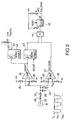
- the internal circuitry of the monitoring device 20 is shown in Figure 2.
- the voltage of the inner conductor of the cable 10 appears on an input line 30 of the Figure 2 circuitry.
- This voltage is fed to a short-term averaging circuit formed by a diode 31, resistor 32, capacitor 33 and resistor 29; the values of these components are chosen such that the voltage of the capacitor 33 tracks the envelope of the data packets appearing on the cable 10 rather than the individual pulses within the packet.
- the voltage of the capacitor 33 is supplied to the "-" inputs of comparators 34 and 37, the "+” inputs of which are respectively supplied with a reference voltage V R1 generated by a chain of resistors 35, 36, and a voltage V R2 generated by a chain of resistors 38, 39.
- Reference voltage V R1 is set at a level less negative than the envelope of a single data packet whereby the output of the comparator 34 will go high in the presence of a data packet on the LAN but will otherwise be low.
- Reference voltage V R2 is set such that it is more negative than the voltage envelope of a single packet but is less negative than the voltage envelope produced when two packets collide; the output of the comparator 37 will thus normally be low but go high upon the occurrence of a collision and remain high while the collision continues.
- the output of the comparator 34 thus indicates the presence of a packet while the output of the comparator 37 indicates the presence of a collision.
- the output of the comparator 34 is fed to a monostable 43 triggered off the positive going edge of the pulse produced at the output of the comparator 34 when a packet is present on the LAN.
- the monostable 43 produces a positive pulse of a duration corresponding to the time interval after the start of a packet when a valid collision may occur.
- the parameters effecting the value of this time interval have already been mentioned above and the monostable is preferably such that the duration of this output pulse can be adjusted appropriately for different LANs.
- latch 45 activates a visual output in the form of an LED (light emitting diode) 46 to thereby indicate to the user of the monitoring device the occurrence of a late collision on the LAN.
- LED light emitting diode
- the monitoring device circuitry can be arranged to provide a low traffic indication.
- the output of the comparator 34 is fed to a monostable 40 which effectively acts as a pulse stretcher.
- the monostable 40 is triggered to produce a corresponding low output pulse at a normally-high inverting output 50.
- the duration of this output pulse is many times greater than that of the packet giving rise to the pulse.
- This extended pulse is used to energize an LED (light emitting diode) 42 to provide the operator with a visual indication of the presence of packet on the LAN.
- the LED 42 When the traffic on the LAN is low, the LED 42 will be seen to flicker; however, in the presence of normal high traffic on the LAN the LED will be continually energized. This simple visual indication of low traffic can be an extremely useful tool in tracking down LAN faults.
- the latch 45 may be replaced by a monostable operative to give an extended output pulse so that the presence of a late collision will be seen by the user of the monitoring device as a fixed duration energization of the LED 46.
- a possible modification to the low traffic indicator would be to use a non-inverting output from the monostable 40 such that in the absence of traffic the LED 42 would be continuously energized, in the presence of low traffic the LED would flicker, while during normal traffic the LED would be de-energized.
- Another possible modification would be to use the output of the monostable 40 to gate the output of a sound source in order to produce an audibly discernible indicator of low traffic rather than a visual one.
- monitoring device is intended for use with a coaxial cable, baseband LAN, it will be apparent to persons skilled in the art that similar monitoring devices could be made for LANs including optical cables or for LANs using broadband signalling techniques rather than baseband techniques.
- the monitoring device described above is of hand-portable form, the device could also be provided as a card for insertion into a station 11 or spanning device 14.
Abstract
A monitoring device (20) is provided for detecting late packet collisions on CSMA/CD LANs (10). The device (20) comprises a first detector (34) for detecting the presence of a packet on a LAN 10, a second detector (37) for detecting the occurrence of a packet collision on the LAN, and a late-collision indicator (43-46) which provides a late-collision indication whenever the second detector (37) detects the occurrence of a collision more than a predetermined time after the first detector (34) detects the presence of a packet. The monitoring device (20) may also be provided with a low-traffic indicator (42) arranged to flicker in the presence of low traffic on the LAN.
Description
- The present invention relates to a method and apparatus for monitoring packet-based LANs (local area networks) that utilize the media access control method known as CSMA/CD (Carrier Sense Multiple Access with Collision Detection).
- As is well known, in a CSMA/CD LAN a number of stations are interconnected through a single shared cable (electrical or optical) logically configured as a bus (though possibly physically configured as a bus, tree or star). Data is transmitted between the stations in packets and generally signals are normally only present on the LAN when user data or control data is being transferred (that is, the LAN is idle - no signals present - in the gaps between packets). A station wishing to transmit data first checks that the LAN has been idle long enough for all transmissions to have propagated across the LAN; providing this check shows the LAN to be idle, the station then proceeds to transmit its data. It is, of course, still possible for two stations to start transmission at approximately the same instant and in this case there will be a collision between the two packets being transmitted. Each transmitting station listens out for any such collision and if one does occur, the station ceases transmission after having first transmitted a jam sequence that ensures the collision is detected by all the stations concerned. The stations responsible for transmitting the colliding packets will then attempt to retransmit their data after a short, random, delay.
- If the LAN is functioning correctly, collisions should only occur within a predetermined time interval following the start of transmission by any particular station. The duration of this time interval is dependent on the longest propagation delay between any pair of stations on the network (or where the network is made up of several segments interconnected by repeaters, between any pair of stations on the relevant network segment), the time taken by a station to launch a packet, and the time taken for a station to detect a collision. In practice, where a LAN is designed in accordance with a particular technical standard, this predetermined time interval will normally be determined with reference to the maximum values of the defining parameters as set down in the technical standard.
- In some LAN fault conditions, packet collisions may occur after the initial time interval where such collisions are expected. It is possible to observe such collisions using network analyzers; however, such items of equipment are expensive and complex, requiring much skill to set them up to observe late collisions.
- It is an object of the present invention to provide a method and apparatus that facilitate the monitoring of late collisions on CSMA/CD LANs.
- According to one aspect of the present invention, there is provided apparatus for monitoring a CSMA/CD LAN, characterized in that said apparatus comprises:
- input means for providing a connection to said LAN to enable monitoring of the LAN whilst active;
- first detection means coupled to said input means and operative to detect the presence of a packet on the LAN and to generate a first output signal in response thereto;
- second detection means coupled to said input means and operative to detect a packet collision on the LAN and to generate a second output signal in response thereto; and
- late-collision indicator means connected to receive said first and second output signals and operative to provide a late-collision output indication when said second output signal indicates the occurrence of a packet collision subsequent to the elapse of a predetermined time interval from the start of the last preceding packet as indicated by said first output signal.
- The late-collision output indication, which is preferably a visual output, enables a user of the apparatus to readily discern the presence of late collisions and therefore of a fault on the LAN.
- Advantageously, the late-collision detector means comprises timing means operative to generate an inhibit signal in response to said first output signal indicating the start of a packet on the LAN, said inhibit signal having a duration, from the time said first output signal indicates the start of the last preceding packet, corresponding to said predetermined time interval; and gating means connected to receive said second output signal and said inhibit signal and operative to provide a late-collision signal only when said inhibit signal is absent concurrently with said second output signal being present; the late-collision signal provided by said gating means being used to provide said late-collision output indication. The timing means may be a re-triggerable monostable.
- Preferably, the late-collision detector means further comprises an output latch connected to receive the said late-collision signal from the gating means, said output latch being operative to latch said late-collision signal on receipt and to thereupon provide said late-collision output indication.
- For monitoring LANs that employ a transmission medium adapted to carry electrical signals, the apparatus may be designed such that said first detection means is operative to provide said first output signal when the voltage on the LAN exceeds a first predetermined voltage magnitude; and said second detection means is operative to provide said second output signal when the voltage in the LAN exceeds a second predetermined voltage magnitude, greater than said first predetermined magnitude.
- The apparatus may advantageously be provided in hand-portable form to permit user to move quickly between test locations. Furthermore, the said predetermined time interval that determines whether or not a collision is classed as a late collision, may be made adjustable.
- According to another aspect of the present invention, there is provided a method of monitoring a CSMA/CD LAN, characterized in that said method comprises the step of detecting the presence of a packet on the LAN and providing a first output signal in response thereto; detecting a packet collision on the LAN and providing a second output signal in response thereto; and providing a late-collision output indication when said second output signal indicates the occurrence of a packet collision subsequent to the elapse of a predetermined time interval from the start of the last preceding packet as indicated by said first output signal.
- According to a further aspect of the present invention, there is provided apparatus for monitoring a CSMA/CD LAN, said apparatus comprising input means for providing a connection to said LAN to enable monitoring of the LAN whilst active; packet detection means coupled to said input means and operative to detect the presence of a packet on the LAN and to generate a first output signal in response thereto; extended-pulse means connected to receive the first output signal and operative to generate for each packet indicated thereby, an extended output pulse of a predetermined duration substantially greater than said packet, and visual indicator means connected to receive each said output pulse and operate to cause a visually or audibly discernible effect for the duration of each pulse whereby to permit low activity in the LAN to be visually discernible by an operator.
- A hand-portable LAN monitoring device embodying the invention will now be particularly described, by way of non-limiting example, with reference to the accompanying diagrammatic drawings, in which:
- Figure 1
- illustrates generally how the monitoring device is used to monitor a LAN; and
- Figure 2
- is a schematic diagram of the monitoring circuitry of the monitoring device.
- Figure 1 illustrates a LAN segment the transmission medium of which is constituted by a
coaxial cable 10. A number ofcomputer workstations 11 are connected to thecable 10 viaconnectors 12. The ends of thecable 10 are terminated byterminators 13 which match the characteristic impedance of thecable 10. - The illustrated LAN is, for example, a CSMA/CD LAN complying with the 10BASE5 variant of the IEEE 802.3 standard. In this case, the characteristic impedance of the
coaxial cable 10 is 50 ohms and theterminators 13 can be simply constituted by 50 ohm resistors connected between the inner conductor and the outer shield of the cable. The signalling technique used is baseband with Manchester encoding and with a data rate of 10 megabits/second. - In transmitting packets over the LAN cable, the stations output pulse signals which have negative voltage excursions relative to the voltage of the cable between the packets (in this case, zero volts).
- The LAN segment may be connected to one or more
other LAN segments 15 viaconnectors 12 and one or more appropriate spanning devices such as thebridge 14. - Also illustrated in Figure 1 is the hand-portable
LAN monitoring device 20. This device is battery powered and is provided with a coaxial-cable connector 21 for connecting the device to thecable 10 through a T-junction cable connector 16. Such connectors are generally to be found throughout the length of theLAN segment cable 10 and can serve as theconnectors 12. When not providing a connection to thecable 10, theconnector 16 has its unconnected stub left not terminated. - As can be seen in Figure 1, the
monitoring device 20 includes a power on/off switch 22, a first LED (light emitting diode)indicator 42 marked "LOW" for indicating low traffic conditions, and asecond LED indicator 46 marked "LATE" for indicating late collisions on the LAN. - The internal circuitry of the
monitoring device 20 is shown in Figure 2. Upon connection of themonitoring device 20 to theLAN cable 10 via theconnectors cable 10 appears on aninput line 30 of the Figure 2 circuitry. This voltage is fed to a short-term averaging circuit formed by adiode 31,resistor 32,capacitor 33 andresistor 29; the values of these components are chosen such that the voltage of thecapacitor 33 tracks the envelope of the data packets appearing on thecable 10 rather than the individual pulses within the packet. - The voltage of the
capacitor 33 is supplied to the "-" inputs ofcomparators resistors 35, 36, and a voltage VR2 generated by a chain ofresistors comparator 34 will go high in the presence of a data packet on the LAN but will otherwise be low. Reference voltage VR2 is set such that it is more negative than the voltage envelope of a single packet but is less negative than the voltage envelope produced when two packets collide; the output of thecomparator 37 will thus normally be low but go high upon the occurrence of a collision and remain high while the collision continues. - The output of the
comparator 34 thus indicates the presence of a packet while the output of thecomparator 37 indicates the presence of a collision. - The output of the
comparator 34 is fed to a monostable 43 triggered off the positive going edge of the pulse produced at the output of thecomparator 34 when a packet is present on the LAN. The monostable 43 produces a positive pulse of a duration corresponding to the time interval after the start of a packet when a valid collision may occur. The parameters effecting the value of this time interval have already been mentioned above and the monostable is preferably such that the duration of this output pulse can be adjusted appropriately for different LANs. - By using the signals present at the output of the
monostable 43 and at the output of thecomparator 37, it is a simple matter to generate a signal indicative of the presence of a late collision of the LAN. More particularly, this can be achieved by feeding theoutput comparator 37 to a normal input of anAND gate 44 whilst feeding the output of the monostable 43 to an inverting input of thesame AND gate 44. Thegate 44 will thus be inhibited for the valid-collision time interval that follows that start of each packet of the LAN; beyond this valid-collision time interval, the output of themonostable 43 serves to enable thegate 44 so that should a collision subsequently occur whilst the currently detected packet is still present, then the collision signal output by thecomparator 37 will be past through thegate 44. This signal is then latched bylatch 45. In its latched state, thelatch 45 activates a visual output in the form of an LED (light emitting diode) 46 to thereby indicate to the user of the monitoring device the occurrence of a late collision on the LAN. - In addition to providing an indication of a late collision on the LAN, the monitoring device circuitry can be arranged to provide a low traffic indication. To this end, the output of the
comparator 34 is fed to a monostable 40 which effectively acts as a pulse stretcher. Upon thecomparator 34 producing an output pulse indicating the presence of a packet on the LAN (this pulse having a duration substantially corresponding to that of the packet), the monostable 40 is triggered to produce a corresponding low output pulse at a normally-high invertingoutput 50. The duration of this output pulse is many times greater than that of the packet giving rise to the pulse. This extended pulse is used to energize an LED (light emitting diode) 42 to provide the operator with a visual indication of the presence of packet on the LAN. When the traffic on the LAN is low, theLED 42 will be seen to flicker; however, in the presence of normal high traffic on the LAN the LED will be continually energized. This simple visual indication of low traffic can be an extremely useful tool in tracking down LAN faults. - Various modifications to the described circuitry will be apparent to persons skilled in the art. Thus for example, the
latch 45 may be replaced by a monostable operative to give an extended output pulse so that the presence of a late collision will be seen by the user of the monitoring device as a fixed duration energization of theLED 46. - A possible modification to the low traffic indicator would be to use a non-inverting output from the monostable 40 such that in the absence of traffic the
LED 42 would be continuously energized, in the presence of low traffic the LED would flicker, while during normal traffic the LED would be de-energized. Another possible modification would be to use the output of the monostable 40 to gate the output of a sound source in order to produce an audibly discernible indicator of low traffic rather than a visual one. - Although the illustrated monitoring device is intended for use with a coaxial cable, baseband LAN, it will be apparent to persons skilled in the art that similar monitoring devices could be made for LANs including optical cables or for LANs using broadband signalling techniques rather than baseband techniques.
- Furthermore, whilst the monitoring device described above is of hand-portable form, the device could also be provided as a card for insertion into a
station 11 or spanningdevice 14.
Claims (9)
- Apparatus for monitoring a CSMA/CD LAN, characterized in that said apparatus comprises:- input means (21) for providing a connection to said LAN (10) to enable monitoring of the LAN whilst active;- first detection means (34) coupled to said input means (21) and operative to detect the presence of a packet on the LAN (10) and to generate a first output signal in response thereto;- second detection means (37) coupled to said input means (21) and operative to detect a packet collision on the LAN (10) and to generate a second output signal in response thereto; and- late-collision indicator means (43-45) connected to receive said first and second output signals and operative to provide a late-collision output indication when said second output signal indicates the occurrence of a packet collision subsequent to the elapse of a predetermined time interval from the start of the last preceding packet as indicated by said first output signal.
- Apparatus according to claim 1, wherein said late-collision indicator means (43-45) comprises:- timing means (43) operative to generate an inhibit signal in response to said first output signal indicating the start of a packet on the LAN (10), said inhibit signal having a duration, from the time said first output signal indicates the start of the last preceding packet, corresponding to said predetermined time interval; and- gating means (44) connected to receive said second output signal and said inhibit signal and operative to provide a late-collision signal only when said inhibit signal is absent concurrently with said second output signal being present; the late-collision signal provided by said gating means (44) being used to provide said late-collision output indication.
- Apparatus according to claim 2, wherein said timing means (43) is a re-triggerable monostable element.
- Apparatus according to claim 2, wherein the late-collision indicator means further comprises an output latch (45) connected to receive the said late-collision signal from the gating means(44) said output latch (45) being operative to latch said late-collision signal on receipt and to thereupon provide said late-collision output indication.
- Apparatus according to claim 1, wherein said late-collision indicator means includes means for adjusting the duration of said predetermined time interval.
- Apparatus according to claim 1 for use with a LAN that employs a transmission medium (10) adapted to carry electrical signals, wherein:- said first detection means (34) is operative to provide said first output signal when the voltage on the LAN exceeds a first predetermined voltage magnitude; and- said second detection means (37) is operative to provide said second output signal when the voltage in the LAN exceeds a second predetermined voltage magnitude, greater than said first predetermined magnitude.
- Apparatus according to claim 1 in the form of a hand-held instrument (20).
- A method of monitoring a CSMA/CD LAN, characterized in that said method comprises the step of:- detecting the presence of a packet on the LAN and providing a first output signal in response thereto;- detecting a packet collision on the LAN and providing a second output signal in response thereto; and- providing a late-collision output indication when said second output signal indicates the occurrence of a packet collision subsequent to the elapse of a predetermined time interval from the start of the last preceding packet as indicated by said first output signal.
- Apparatus for monitoring a CSMA/CD LAN, said apparatus comprising:- input means (21) for providing a connection to said LAN (10) to enable monitoring of the LAN whilst active;- packet detection means (34) coupled to said input means (21) and operative to detect the presence of a packet on the LAN (10) and to generate a first output signal in response thereto;- extended-pulse means (40) connected to receive the first output signal and operative to generate for each packet indicated thereby, an extended output pulse of a predetermined duration substantially greater than said packet, and- visual indicator means (42) connected to receive each said output pulse and operative to cause a visually or audibly discernible effect for the duration of each pulse whereby to permit low activity in the LAN to be visually discernible by an operator.
Priority Applications (3)
| Application Number | Priority Date | Filing Date | Title |
|---|---|---|---|
| EP90313320A EP0489990A1 (en) | 1990-12-07 | 1990-12-07 | LAN monitoring method and apparatus |
| PCT/GB1991/001952 WO1992010896A1 (en) | 1990-12-07 | 1991-11-06 | Lan monitoring method and apparatus |
| US08/066,141 US5329519A (en) | 1990-12-07 | 1991-11-06 | Lan monitoring method and apparatus |
Applications Claiming Priority (1)
| Application Number | Priority Date | Filing Date | Title |
|---|---|---|---|
| EP90313320A EP0489990A1 (en) | 1990-12-07 | 1990-12-07 | LAN monitoring method and apparatus |
Publications (1)
| Publication Number | Publication Date |
|---|---|
| EP0489990A1 true EP0489990A1 (en) | 1992-06-17 |
Family
ID=8205639
Family Applications (1)
| Application Number | Title | Priority Date | Filing Date |
|---|---|---|---|
| EP90313320A Withdrawn EP0489990A1 (en) | 1990-12-07 | 1990-12-07 | LAN monitoring method and apparatus |
Country Status (3)
| Country | Link |
|---|---|
| US (1) | US5329519A (en) |
| EP (1) | EP0489990A1 (en) |
| WO (1) | WO1992010896A1 (en) |
Cited By (4)
| Publication number | Priority date | Publication date | Assignee | Title |
|---|---|---|---|---|
| GB2276066A (en) * | 1993-03-12 | 1994-09-14 | Daimler Benz Ag | Device for monitoring balanced two-wire bus lines and two-wire bus interfaces |
| GB2288522A (en) * | 1994-04-11 | 1995-10-18 | Daimler Benz Ag | Monitoring a two-wire bus system for faults |
| US6256318B1 (en) | 1997-08-29 | 2001-07-03 | 3Com Corporation | Network hub activity display |
| ITRM20090114A1 (en) * | 2009-03-17 | 2010-09-18 | Gruppo Galli Srl | IMPEDANCE ADAPTER FOR DIGITAL TRANSMISSIVE SYSTEMS WITH SELF-POWERED OPTICAL SIGNAL |
Families Citing this family (8)
| Publication number | Priority date | Publication date | Assignee | Title |
|---|---|---|---|---|
| US5701451A (en) * | 1995-06-07 | 1997-12-23 | International Business Machines Corporation | Method for fulfilling requests of a web browser |
| EP0878078A2 (en) * | 1996-01-29 | 1998-11-18 | Lecroy Corporation | Packet network monitoring device |
| US5878030A (en) * | 1996-06-19 | 1999-03-02 | Wandel & Goltermann Technologies, Inc. | Test access port for analyzing high-speed local area network switched environment |
| US6229817B1 (en) * | 1997-12-18 | 2001-05-08 | Advanced Micro Devices, Inc. | System and method for programming late collision slot time |
| US6169475B1 (en) * | 1998-03-30 | 2001-01-02 | Xircom, Inc. | System and method for active detection of connection to a network |
| US6829223B1 (en) | 1998-12-31 | 2004-12-07 | Vigilant Networks Llc | Computer network physical-layer analysis method and system |
| US20020061309A1 (en) * | 2000-03-08 | 2002-05-23 | Garger Stephen J. | Production of peptides in plants as N-terminal viral coat protein fusions |
| US20020129098A1 (en) * | 2001-03-06 | 2002-09-12 | Dennis Stone | LAN connection status display |
Citations (4)
| Publication number | Priority date | Publication date | Assignee | Title |
|---|---|---|---|---|
| FR2577368A1 (en) * | 1985-02-12 | 1986-08-14 | Electricite De France | Device for analyzing traffic on a local data transmission network |
| EP0213063A1 (en) * | 1985-08-22 | 1987-03-04 | Siemens Aktiengesellschaft | Circuit arrangement for testing a passive bus network (CSMA/CD access method) |
| US4890102A (en) * | 1987-05-26 | 1989-12-26 | Cabletron, Inc. | Visual display for communication network monitoring and troubleshooting |
| EP0375243A1 (en) * | 1988-12-22 | 1990-06-27 | The Whitaker Corporation | Packet network timing analyzer |
Family Cites Families (4)
| Publication number | Priority date | Publication date | Assignee | Title |
|---|---|---|---|---|
| US4779088A (en) * | 1985-11-18 | 1988-10-18 | American Telephone And Telegraph Company | Collision detection arrangement for daisy chain configurations |
| US5012467A (en) * | 1989-10-10 | 1991-04-30 | 3Com Corporation | Method and apparatus for collision detection in a local area network transceiver |
| US5185735A (en) * | 1991-07-10 | 1993-02-09 | Hewlett Packard Company | Lan noise monitor |
| US5267237A (en) * | 1992-07-07 | 1993-11-30 | Digital Equipment Corporation | Collison detection and signaling circuit |
-
1990
- 1990-12-07 EP EP90313320A patent/EP0489990A1/en not_active Withdrawn
-
1991
- 1991-11-06 US US08/066,141 patent/US5329519A/en not_active Expired - Lifetime
- 1991-11-06 WO PCT/GB1991/001952 patent/WO1992010896A1/en active Application Filing
Patent Citations (4)
| Publication number | Priority date | Publication date | Assignee | Title |
|---|---|---|---|---|
| FR2577368A1 (en) * | 1985-02-12 | 1986-08-14 | Electricite De France | Device for analyzing traffic on a local data transmission network |
| EP0213063A1 (en) * | 1985-08-22 | 1987-03-04 | Siemens Aktiengesellschaft | Circuit arrangement for testing a passive bus network (CSMA/CD access method) |
| US4890102A (en) * | 1987-05-26 | 1989-12-26 | Cabletron, Inc. | Visual display for communication network monitoring and troubleshooting |
| EP0375243A1 (en) * | 1988-12-22 | 1990-06-27 | The Whitaker Corporation | Packet network timing analyzer |
Non-Patent Citations (2)
| Title |
|---|
| INTERNATIONAL TEST CONFERENCE 1987 September 1987, IEEE NEW YORK US pages 136 - 146; B.SCHUSHEIM: 'AUTOMATIC TEST OF LAN TRANCEIVERS ' * |
| NACHRICHTEN ELEKTRONIK UND TELEMATIK. vol. 40, no. 10, October 1986, HEIDELBERG DE pages 409 - 413; A.RUPP: 'AUFBAU UND MESSUNGEN AM ETHERNET ' * |
Cited By (8)
| Publication number | Priority date | Publication date | Assignee | Title |
|---|---|---|---|---|
| GB2276066A (en) * | 1993-03-12 | 1994-09-14 | Daimler Benz Ag | Device for monitoring balanced two-wire bus lines and two-wire bus interfaces |
| US5483639A (en) * | 1993-03-12 | 1996-01-09 | Mercedes-Benz Ag | Device for detecting transmission errors in balanced two-wire bus lines and two-bus interfaces |
| GB2276066B (en) * | 1993-03-12 | 1996-06-26 | Daimler Benz Ag | Device for monitoring balanced two-wire bus lines and two-wire bus interfaces |
| GB2288522A (en) * | 1994-04-11 | 1995-10-18 | Daimler Benz Ag | Monitoring a two-wire bus system for faults |
| GB2288522B (en) * | 1994-04-11 | 1998-07-08 | Daimler Benz Ag | Monitoring means for monitoring a two-wire bus system |
| US5781585A (en) * | 1994-04-11 | 1998-07-14 | Daimler Benz Aktiengesellschaft | Arrangement for monitoring a two-wire bus line |
| US6256318B1 (en) | 1997-08-29 | 2001-07-03 | 3Com Corporation | Network hub activity display |
| ITRM20090114A1 (en) * | 2009-03-17 | 2010-09-18 | Gruppo Galli Srl | IMPEDANCE ADAPTER FOR DIGITAL TRANSMISSIVE SYSTEMS WITH SELF-POWERED OPTICAL SIGNAL |
Also Published As
| Publication number | Publication date |
|---|---|
| US5329519A (en) | 1994-07-12 |
| WO1992010896A1 (en) | 1992-06-25 |
Similar Documents
| Publication | Publication Date | Title |
|---|---|---|
| EP0691546B1 (en) | Time-domain reflectometer for testing coaxial cables | |
| US7414410B2 (en) | Cable diagnostics using time domain reflectometry and application using the same | |
| US8699356B2 (en) | Method and system for diagnosing a fault or open circuit in a network | |
| AU724885B2 (en) | Method and system for characterizing terminations in a local area network | |
| US5381348A (en) | Token ring local area network testing apparatus using time delay reflectory | |
| US5329519A (en) | Lan monitoring method and apparatus | |
| US5309428A (en) | Token ring local area network testing apparatus for phase jitter testing | |
| US5444695A (en) | Token ring local area network testing apparatus providing station history information | |
| US5363366A (en) | Token ring local area network testing apparatus for obtaining beacon domain information | |
| EP0524726B1 (en) | LAN noise monitor | |
| US20040198105A1 (en) | Apparatus & method for configuring network media connections | |
| EP0632620A2 (en) | Backoff time evaluation method for ethernet | |
| US5365513A (en) | Token ring local area network testing apparatus for matching its speed to ring speed | |
| JP2000505604A (en) | Packet network monitor | |
| WO1999013575A1 (en) | Method and apparatus for detecting collisions on a network | |
| US20060164998A1 (en) | System and method for detecting added network connections including wiretaps | |
| US5425017A (en) | Token ring local area network testing apparatus inserted in an active "T" co | |
| US9664496B2 (en) | Cable length determination using variable-width pulses | |
| US4730307A (en) | Method and apparatus for local area networks | |
| EP0324012B1 (en) | Shorted-coaxial-cable detector for local-area networks | |
| JPH0773265B2 (en) | Network including multiple stations | |
| CN113009246B (en) | PSE device detection device and PSE device detection method | |
| JP2988529B2 (en) | Fault diagnosis device | |
| GB2158679A (en) | Testing a local area network | |
| JPH0254984B2 (en) |
Legal Events
| Date | Code | Title | Description |
|---|---|---|---|
| PUAI | Public reference made under article 153(3) epc to a published international application that has entered the european phase |
Free format text: ORIGINAL CODE: 0009012 |
|
| AK | Designated contracting states |
Kind code of ref document: A1 Designated state(s): DE FR GB IT |
|
| 17P | Request for examination filed |
Effective date: 19921127 |
|
| 17Q | First examination report despatched |
Effective date: 19951102 |
|
| STAA | Information on the status of an ep patent application or granted ep patent |
Free format text: STATUS: THE APPLICATION IS DEEMED TO BE WITHDRAWN |
|
| 18D | Application deemed to be withdrawn |
Effective date: 19960316 |