EP0490478A2 - Automatic compilation of model equations into a gradient based analog simulator - Google Patents
Automatic compilation of model equations into a gradient based analog simulator Download PDFInfo
- Publication number
- EP0490478A2 EP0490478A2 EP91309918A EP91309918A EP0490478A2 EP 0490478 A2 EP0490478 A2 EP 0490478A2 EP 91309918 A EP91309918 A EP 91309918A EP 91309918 A EP91309918 A EP 91309918A EP 0490478 A2 EP0490478 A2 EP 0490478A2
- Authority
- EP
- European Patent Office
- Prior art keywords
- model
- code
- parse trees
- argument
- scalar
- Prior art date
- Legal status (The legal status is an assumption and is not a legal conclusion. Google has not performed a legal analysis and makes no representation as to the accuracy of the status listed.)
- Withdrawn
Links
Images


Classifications
-
- H—ELECTRICITY
- H04—ELECTRIC COMMUNICATION TECHNIQUE
- H04N—PICTORIAL COMMUNICATION, e.g. TELEVISION
- H04N1/00—Scanning, transmission or reproduction of documents or the like, e.g. facsimile transmission; Details thereof
- H04N1/00681—Detecting the presence, position or size of a sheet or correcting its position before scanning
- H04N1/00684—Object of the detection
- H04N1/00708—Size or dimensions
-
- G—PHYSICS
- G06—COMPUTING; CALCULATING OR COUNTING
- G06F—ELECTRIC DIGITAL DATA PROCESSING
- G06F30/00—Computer-aided design [CAD]
- G06F30/30—Circuit design
- G06F30/36—Circuit design at the analogue level
- G06F30/367—Design verification, e.g. using simulation, simulation program with integrated circuit emphasis [SPICE], direct methods or relaxation methods
-
- H—ELECTRICITY
- H04—ELECTRIC COMMUNICATION TECHNIQUE
- H04N—PICTORIAL COMMUNICATION, e.g. TELEVISION
- H04N1/00—Scanning, transmission or reproduction of documents or the like, e.g. facsimile transmission; Details thereof
- H04N1/00681—Detecting the presence, position or size of a sheet or correcting its position before scanning
- H04N1/00684—Object of the detection
- H04N1/00718—Skew
-
- H—ELECTRICITY
- H04—ELECTRIC COMMUNICATION TECHNIQUE
- H04N—PICTORIAL COMMUNICATION, e.g. TELEVISION
- H04N1/00—Scanning, transmission or reproduction of documents or the like, e.g. facsimile transmission; Details thereof
- H04N1/00681—Detecting the presence, position or size of a sheet or correcting its position before scanning
- H04N1/00729—Detection means
- H04N1/00734—Optical detectors
- H04N1/00737—Optical detectors using the scanning elements as detectors
-
- H—ELECTRICITY
- H04—ELECTRIC COMMUNICATION TECHNIQUE
- H04N—PICTORIAL COMMUNICATION, e.g. TELEVISION
- H04N1/00—Scanning, transmission or reproduction of documents or the like, e.g. facsimile transmission; Details thereof
- H04N1/00681—Detecting the presence, position or size of a sheet or correcting its position before scanning
- H04N1/00763—Action taken as a result of detection
- H04N1/00774—Adjusting or controlling
- H04N1/00779—Adjusting settings, e.g. mode, feeding rate or type of paper
Definitions
- This invention relates to the field of electrical circuit simulators, and more particularly to the field of entering analog electrical component model descriptions into a gradient based analog circuit simulator.
- Circuit simulators represent the circuit under design in mathematical terms, allowing numerical analysis procedures to be performed which correspond to the measurements that formerly were made with physical hardware in the laboratory.
- the output of the simulator program is in effect the result of a measurement made on the circuit under design as it presently has been specified within the simulator.
- simulators have been hindered, however, by the difficulty of adding new device models to libraries of such models.
- the simulators are built and maintained by software engineers, who are comfortable with computer programming, but who frequently have a somewhat limited knowledge of device physics.
- the physicists who develop models for new devices tend to have a limited knowledge of software and would prefer not to have to become extremely conversant with it in order to add their model to a library of such models.
- the Saber TM system pre-calculates tables of model branch values and gradient data and then uses those tables and piecewise linear approximation to produce solution vectors.
- the Saber TM system pre-calculates tables of model branch values and gradient data and then uses those tables and piecewise linear approximation to produce solution vectors.
- the tables must be re-calculated using a finer grid, whereas in a system based on the symbolic relationships being compiled into the main simulation code, a more accurate calculation can be obtained more directly by varying the control parameter, such as the convergence tolerances or transient operator approximation tolerances, and then re-running the simulation immediately.
- the control parameter such as the convergence tolerances or transient operator approximation tolerances
- What is desired is a method that allows analog device models to be effectively described in a language that is easy to learn and use, and then to have that description converted into the language of the simulator and automatically compiled and linked into the main program used by the simulator in a way that allows high speed calculation of solutions of gradient-based equations without the use of piecewise linear approximation and the need to build and use tables.
- the present invention is a method that allows analog device model descriptions to be effectively described in a language that is easy to learn and use, and to have that description converted into the language of the simulator and automatically compiled and linked into the main program used by the simulator in a way that allows actual high speed calculation of gradient-based equations without the use of piecewise linear approximation and the need to build and use tables.
- the method of the present invention encompasses the following steps: entering a high-level description of the component model by naming the model, declaring parameters, specifying argument-independent equations, describing a topology of the model, declaring arguments, and specifying argument-dependent equations.
- model behavior code parse trees and model structure data compiling the high-level description to produce model behavior code parse trees and model structure data, analyzing the data-flow of the model behavior code parse trees to produce verified parse trees and error messages for those variables referenced but not defined, debugging the model description as represented by the model behavior code parse trees and model structure data, translating the verified parse trees to produce scalar-code parse trees according to a selected translation mode, the scalar code parse trees including objects representing arithmetic operators that permit said operators to manipulate expressions containing derivatives with respect to an argument, checking the argument dependence of the scalar-code parse trees to produce repartitioned scalar code parse trees, and filling in the data required by simulator model templates to convert the repartitioned scalar code parse trees into code in the computer programming language used by the simulator.
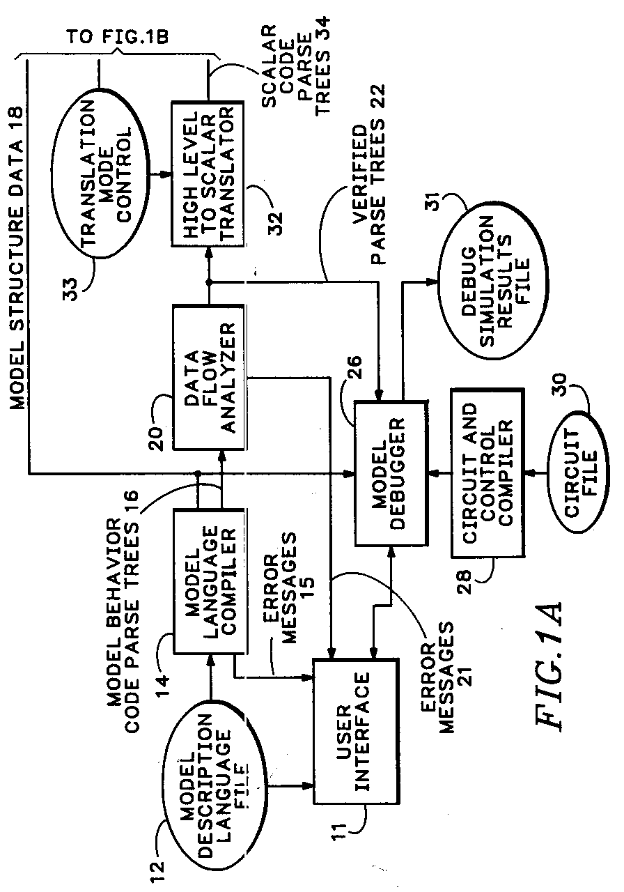
- a gradient-based analog simulator 10 has been provided with means for accomplishing the methods of the present invention.
- the user enters data describing the user's model for an analog circuit device into a model description language file 12.
- the language used, the Analog Device Model Description Language has been designed to foster good communication between a device physicist and the software intensive environment of the analog circuit simulator 10. It permits a rigorous definition of the analog device model while insulating the user from the details of simulation software.
- the block-oriented structure of this language guides the model developer through the requirements for a complete model description.
- a model language compiler 14 performs lexical and syntax analysis of the model description from the model description language file 12 and produces model behavior code parse trees 16 and model structure data 18.
- the model behavior code parse trees are forwarded to a data flow analyzer 20 which verifies that all referenced variables are defined.
- the output of the data flow analyzer 20 is verified parse trees 22. If a variable is referenced but not defined, an error message 21 is generated.
- the verified parse trees 22 and model data structures 18 are both available to a model debugger 26 that also receives input from a circuit and control compiler 28 operating on the data in circuit file 30.
- the circuit file 30 is a smaller, local version of the same kind of information that is found in the circuit netlists 46 and the analysis control program 48 associated with the analog circuit simulator 10.
- the user controls the model debugger 26 through the user interface 11 to produce a debug simulation results file 31.
- the model debugger 26 has interactive capabilities that allow the user to examine the values of all of the variables in the context of the execution of any statement. These capabilities and the error messages generated help the user find any errors in the model description language file 12.
- model behavior code parse trees and the verified parse trees derived from them can be linked to a unique class of objects that are capable of performing arithmetic and algebraic operations on operands that contain not only variables but their partial derivatives.
- "FAndGradF" (function and gradient of the function; Appendix E) is the name of a calculating version of this class of objects that is used in the model debugger 26 to numerically evaluate the verified parse trees 22.
- the verified parse trees 22 also go to a high level to scalar translator 32 which produces scalar code parse trees 34.
- the high level to scalar translator 32 adds parse nodes representing the derivatives of all quantities with respect to their arguments.
- the arguments are those variables declared in the argument-definition section of the Analog Model Description Language procedure.
- the arguments are the model parameters with respect to which the sensitivities are to be found.
- the arguments are the noise sources in the code, defined using the noise function.
- the argument dependence analyzer 36 optimizes the code by first running a more complete data flow analysis, which includes the derivatives with respect to arguments as well as the original equations. If this analysis finds variables that are defined but never used, the definitions are discarded. The argument-dependent equations are then checked to verify that they truly are argument-dependent and those that are not are moved to the argument-independent portion of the code to produce repartitioned scalar code parse trees 38. This repartitioning is necessary because the process of differentiation may turn a variable into a constant.
- a C code model printer 40 receives the translation mode data 33, the repartitioned scalar code parse trees 38 and the model structure data 18 and uses TekSpice2 simulator model templates 42 to organize and convert those inputs into a C code output, the TekSpice2 model file 44 that is suitable for linking into the main simulation program of the analog circuit simulator 10.
- the TekSpice2 simulator model templates 42 help define the C code functions expected by the simulator.
- the analog circuit simulator 10 also receives circuit netlists 46 and an analysis control program 48, and, based on the interaction of one or more instances of a number of such models according to the contents of the circuit netlists, produces a simulation results file 50.
- the first step in the method of the present invention is to create a high-level description of the new device model in an easy to use language.
- This language which is called the Analog Model Description Language (AMDL)
- AMDL Analog Model Description Language
- the Analog Model Description Language description of a new model begins with an outer block that defines the name of the new model, in this example "resistor”. Each block begins with a required keyword, in this example "modelDefinition”. " ⁇ sub-blocks ⁇ ” are the model details that are filled in the steps which follow. Comments are identified by a slash and an asterisk, / * comments * /, as in the language C. Taking these together, we have an outer block that looks like:
- the sub-blocks define the parameters, argument-independent equations, topology, arguments, and argument-dependent equations for the new model, in that order.
- Each sub-block contains one or more statements as explained below. Every model must have a topology sub-block and an argument-dependent equations sub-block, but the inclusion of other sub-blocks is optional, depending on the features of the particular model. Variables defined in one block are available for use in equations in the blocks that follow.
- the general form of all sub-blocks is:
- PARAMETER DECLARATION Parameters are variables which assume constant values at simulation time, such as the resistance of a resistor. They are declared using assignment statements. The assignment statements contain the parameter name and a default value, and optionally a legal set of values. The default value may be specified to be anything from negative infinity to positive infinity. Default values may be overridden for particular instances of the use of the model.
- the comma indicates that a legal set of values follows the assignment of the default value. Such a comma and legal set may only appear after an assignment statement.
- the assigned value is tested to see if it is within the legal set. If it is not, an error message is generated.
- a legal set of discrete values may be specified by enumeration, e.g.: ⁇ value1, value2, ... ⁇
- a bracket indicates inclusion of the end point, "lowValue” in this example, while a parenthesis indicates exclusion of the endpoint, "highValue” in this example.
- a legal set may also include the union of two or more sets, where a back-slash forward-slash combination is interpreted as the union operator for sets, e.g.: (-infinity, -0.1] ⁇ / ⁇ 0 ⁇ ⁇ / [0.1, infinity)
- ARGUMENT-INDEPENDENT EQUATIONS Arguments are independent variables whose values are determined repeatedly during every iteration of the simulation. Argument-independent equations only involve parameters and constants, and so only need to be evaluated when parameter values change. These equations often are used for scaling by dimensions, temperature effects, or could be used to map physical parameters into internal electrical parameters. As will be further explained below in connection with Note 2 of Appendix C, the diode model input file, an iterative construct ("while" statement) is provided for local solution of simple nonlinear equations. Legal sets may also be appended to assignment statements in this sub-block. The keyword is "argumentIndependentEquations", and an example using the resistor again is:
- TOPOLOGICAL DESCRIPTION Electrical circuit simulation is naturally facilitated through the construction of nodal networks.
- network constructs for a node, branch and pad are provided to describe the flow of network quantities and provide interconnections for the confluence of those flows.
- This sub-block closely emulates the form of a circuit netlist.
- the statements for defining nodes and pads use the keywords "node” and “pad”, and “units”, and look like this:
- Nodes and branches are private to a model definition, i.e., no branch may join the node of one model definition to the node of a different model definition.
- Pads are special nodes that are the only legal way to connect a particular instance of a model definition to the other network elements in the system.
- the specification of units determines the type of quantities that are associated with particular nodes and pads, so that inconsistent types of quantities, such as voltage and pressure, are not inadvertently connected to the same node or pad.
- Branches are the conduits used to interconnect nodes and pads with other nodes and pads.
- the branch name provides the association between the mathematical equations of the model definition, defined in the argumentDependentEquations sub-block described below, and the branch contribution to the system of which it is a component.
- a "through” quantity is defined by those equations as the flow through the branch.
- For electrical branches the value of "through” is electrical current. "Units” again are used to enforce consistency in network construction.
- branch current may be that required to keep the difference in node voltages across that branch constant.
- An example of this would be the branch joining the terminals of a voltage-source.
- the unknown voltage-source current it is customary to introduce an equation of constraint.
- the model unknown which may represent a network or non-network quantity, provides for this requirement.
- a model unknown provides a mechanism for expressing equations of constraint between the model arguments.
- a model unknown must have an associated constraint equation which may mathematically couple to branches in the network. Additionally, the unknown must be used in at least one of the equations in the model definition.
- the constraint is defined in the argumentDependentEquations section of the model description and the action of the simulator is to adjust the system solution, and hence the model arguments, to drive the expression appearing in the constraint equation to zero.
- the topological description for the resistor example is given by: Note that algorithm-specific information such as matrix stamps are not included in the model description as in other model-definition languages. Such information is extractable by the software of the present invention from branch, unknown, equations, and argument declarations and need not concern the model developer.
- ARGUMENT DECLARATION The arguments are independent variables in the model equations that receive their values from the solution of the system equations.
- An example would be vbe and vbc for a bipolar transistor.
- the polarity variable allows one equation set to be used for models with two polarities, such as npn and pnp transistors.
- argument value(name-of-unknown).
- Arguments will be used for the definition of the mathematical functions and relations of the argumentDependentEquations sub-block. Arguments have the same units as the nodes, pads and unknowns which they reference. The mixing of units is thereby prevented.
- ARGUMENT-DEPENDENT EQUATIONS The argument-dependent equations involve the model arguments as well as parameters and must be evaluated at each iteration during the solution process if a nonlinear system is being solved. All branches must have through values defined and all model unknowns must have constraints expressed in this block.
- the expression appearing above is formed as an equation right-hand side from a set of conventional mathematical functions and operators.
- the action of the simulator is to subtract the through value from the nodal system equation of the first node of the branch and to add to the equation for the second node.
- constraintFor(unknown name) expression and the action of the simulator is to adjust the system solution, and hence the model arguments, to drive the expression appearing in the constraint equation above to zero.
- constraintFor(unknown name) expression
- the Analog Model Description Language assumes the existence in the simulator of standard mathematical support and the approximation operators "ddt()", “delay()”, “bessel2()”, and “integral()".
- the operator “ddt()” is a derivative approximation of the argument with respect to time.
- the other approximation operators “delay()”, “bessel2()”, and “integral()” are needed to implement the standard Spice transmission line and bipolar transistor models, and the not-so-standard Josephson junction model, respectively.
- Appendices A and B are, respectively, "lex” and “yacc” files that together rigorously define the Analog Model Description Language.
- the "lex” file defines the tokens of the Analog Model Description Language, while the “yacc” file defines all of the permitted sequences of those tokens.
- the Analog Model Description Language is highly flexible, in that it allows the user to include as many unknowns as desired in the solution vector. While the desire to reduce simulation time usually leads one to include as few unknowns as possible in the solution vector, different topological forms may exhibit superior behavior numerically due to the approximation methods used to solve the system unknowns.
- the Analog Model Description Language permits such varied descriptions. For example, Appendix N shows an Analog Model Description Language file describing a diode model in a topological form suitable for modified nodal analysis, with three node voltages in the solution vector as system unknowns.
- Appendix O is a similar file, but in a topological form suitable for the tableau method, with three node voltages, two branch currents, and a junction capacitance all appearing in the solution vector as system unknowns.
- Appendix P is yet another such file, but in the modified tableau method, with three node voltages and two branch currents as system unknowns.
- Appendix Q is another file in the modified tableau method, but with only two node voltages and one branch current appearing in the solution vector.
- Appendix U (Prior Art) to this document is a paper, that was given at the 1987 Automated Design and Engineering for Electronics - West conference, entitled “A Simulator for Designing Mixed Technology Systems” by Doug Johnson of Analogy Inc. This paper describes the Saber system and, at page 230, shows an example of the MAST language.
- Appendix R is an example of how the same devices may be defined using the Analog Model Description Language of the present invention. Appendix R contains two pages. The first is the model description for the error amplifier, while the second is the model description for the motor and tachometer.
- the model language compiler 14 provides lexical and syntactical analysis. "Principles of Compiler Design” by Aho and Ullman, Addison-Wesley Publishing Company, (1977), hereby incorporated by reference, explains lexical and syntax analyzers and parser generators.
- the model language compiler 14 is written in SmallTalk-80, although it could be written in other languages, especially other object oriented languages. When the model language compiler 14 is presented with an allowed sequence of tokens, it builds a corresponding object to represent that allowed sequence. When the compiler is presented with a sequence of tokens that is not allowed, it produces an error message 15 for the operator. To optimize its output, the model language compiler also looks for repeated common sub-expressions, and as they are found, sets all references for such a common sub-expression to a single definition.
- the model language compiler 14 produces two outputs, model structure data 18 and model behavior code parse trees 16, in addition to the error messages 15.
- FIG. 2 is an example of a model behavior code parse tree and the equation that it is based on. The present system follows the post-order convention for parse tree traversal.
- the model behavior code parse trees 16 produced by the model language compiler 14 can be linked to "FAndGradF" objects, that permit arithmetic operators to accommodate differentials in the operands that they operate on.
- Model structure data 18 includes an input parameters list and "map-in” and "map-out” data.
- initial arguments and parameters are used by the argument-dependent model code to produce a numerical results file.
- Map-out is the code that is used to transfer the data from the model's numerical results into the linear system equation of a gradient based simulation. Solution of the linear system equations produces a solution vector.
- Map-in is the code that converts the data in the solution vector back into the values of the arguments for the next iteration.
- each iteration consists of: first, mapping-in values from the solution vector to the arguments; next, evaluating argument-dependent equations using those values; and then, mapping-out the "through” and “constraint” quantities into the linear system equations which are solved again to complete the iteration.
- the model debugger 26 accepts the verified parse trees from the data flow analyzer and model structure data from the model language compiler and executes it in a pseudo-machine environment. Because it is not running compiled machine level code but rather using a program to interpret the incoming stream of high level instructions and emulate the behavior of the actual simulator, the execution is much slower than execution of the compiled code produced by the C code model printer. However, this slow execution is a reasonable tradeoff, in that it permits debugging of Analog Model Description Language programs directly in an environment that returns much more meaningful information when errors are encountered, and permits the stepping through of instructions and the viewing of intermediate results and the values of all variables, so that debugging is made feasible in a way that it would not be along the main path through the C code model printer.
- the model debugger 26 is a modified version of the standard SmallTalk-80 debugger. The modifications make it more suitable for executing the verified parse trees 22.
- Each node in these parse trees (FIG. 2) knows how to execute itself in a suitable context containing the values of the variables that it needs.
- the top node then passes the same message to the subtree representing its right-hand-side.
- the subtree nodes to its left keep passing the message down, until the bottom nodes eventually are reached.
- the top node of the right-hand-side subtree eventually receives the information that it needs from the nodes on its left-hand-side, adds the postValue "1" to that, and passes the result back to the top node, the equals sign. The top node then tells the node to its left, "X", to store its new value in the supplied context.
- FIG. 2 is discussed in more detail below, in connection with the C code model printer 40.
- the model debugger 26 calculates partial derivatives using "FAndGradF”, which is explained in detail below.
- “FAndGradF” uses a numerical approach and produces actual values of the variables that it operates on.
- "CodeGenFAndGradF” which is used to replace “FAndGradF” in the high level to scalar translator 32, is analogous, but it uses a symbolic approach and produces C code when it reaches the C code model printer 40. This C code then does the actual numerical calculations after it is linked into the C code of the main program of the Analog Circuit Simulator 10.
- model debugger 26 is executing parse trees instead of regular SmallTalk-80 code, there are some differences in its user interface and the information that is available to the user.
- regular SmallTalk debugger the debugger constructs a map between the source code and the compiled method before it calls the SmallTalk interpreter to perform executions. It is therefore able to print out the source code for the user as he steps through or halts on an instruction.
- model debugger 26 of the present invention there is no interpreter for the compiled model code; it executes itself as described above.
- the model debugger 26 does not create a map between the test representation of the model code and the parse nodes, but rather it asks each code statement to construct a text representation of itself.
- Each node/object of the model behavior code parse trees 16 includes methods for responding to messages making such requests. For example, the top node equal sign of FIG. 2, when presented with such a request, would ask its left-hand-side node to print out its name, then itself print an equal sign, then ask its right-hand-side node to print out its name. The right-hand-side node would have to make similar requests of the nodes below it in order to complete its printout.
- FIG. 3 is a sample screen from the model debugger 26 engaged in the process of debugging a resistor model, r.
- the pane on the left is used to step through code statements or view a statement that has been halted on.
- the panes on the right are used to inspect values stored in variables.
- the pane at the top on the right displays argument values.
- the second pane down on the right displays the values of the "through” and "constraint" variables that will be mapped out into the linear system equations.
- the third pane down on the right displays temporary variables and model outputs.
- the fourth pane down on the right displays input parameters.
- the fifth and final pane on the right displays preset global variables, those that are external to the model definition.
- the resulting verified parse trees 22 are forwarded from the data flow analyzer 20 to the high level to scalar translator 32.
- the high level to scalar translator 32 produces scalar code parse trees 34 that are specialized to perform tests in each of the following modes: dc/bias, transient, ac, noise, and sensitivity.
- the translation mode control 33 informs the high level to scalar translator 32 and the C code model printer 40 about the requirements of each mode.
- the high level to scalar translator 32 produces appropriately different code for efficiently performing the requirements of each mode, so that C code modules for each test are available for selection by the analysis control program 48.
- the high level to scalar translator 32 has the ability to produce SmallTalk-80 objects capable of writing C code representing arithmetic operators that permits those operators to manipulate expressions containing derivatives with respect to a plurality of arguments.
- This capability is fundamental to automatically constructing a C code TekSpice2 model file 44 that includes all of the operations necessary for gradient based nonlinear analysis.
- the same technique could be used with other templates to produce code for other simulators, e.g., Berkeley's Spice3.
- the Saber TM software of the prior art in contrast, numerically evaluates the equations in their compiled language description over a range of space and passes on tables of the results obtained to the generic code of the simulator which interpolates from these tables as needed to perform the simulation.
- the FAndGradF and CodeGenFAndGradF objects have the general form:
- arguments may then be defined as:
- the class of objects FAndGradF contains methods for every arithmetic or algebraic relationship that may occur in an analog model. These include addition, subtraction, multiplication, division, exponentiation, absolute value, trigonometric functions and their inverses and hyperbolics, ceiling, floor, coerce, degrees-to-radians, and radians-to-degrees, fractional-part, integer-part, natural logarithm, logarithm-in-base-y, negation, power-of-ten, real-part, imaginary-part, reciprocal, rounded-off, square-root, minimum, maximum, modulus, raised-to-power-of, and sign. In most cases these methods can operate on either scalar (argument-independent) or gradient (argument-dependent) quantities.
- This result vector has a length the size of the original vector (self) that holds two sets of functions.
- the first part of newVec is y, the function value. This header is generated by the " newVec value: u sin ".
- the (df/du) part of the object, which is cos(u) for this function, is generated by the "fPrime” portion of this line of code. "fPrime” contains the cosine of u as the result of the preceding line of code, " fPrime ⁇ - u cos ".
- the (du/dxN) part of the object, du/dx is generated by the "(self derivativeAt: index)" part of the same line of code.
- the second to the last line of this code stores the derivative value in the result vector.
- the value of the derivative of y with respect to x3 can be obtained by sending a message to the new object identifying the argument index among the set of arguments dxl to dxN.
- the argument can be identified using the construct shown above:
- CodeGenFAndGradF objects create scalar code objects that carry with them the capacity to write themselves out in C code with the help of the C code model printer.
- the methods associated with CodeGenFAndGradF also contain a penchant for code simplification. That is, they pay attention to when variables become zero as a result of differentiation, for example, and they act accordingly to simplify the code that they write to eliminate operations that become meaningless as a result of these occurrences.
- the argument dependence analyzer 36 optimizes the code by checking ostensibly argument-dependent equations to verify that they truly are argument-dependent and moving those that are not to the argument-independent portion of the code to produce repartitioned scalar code parse trees 38.
- Sometimes the process of differentiation turns a variable into a constant, for instance. This repartitioning also increases the speed of execution at run time.
- Appendix C is an Analog Model Description Language file 12 for a diode model.
- Appendix D is a corresponding C code TekSpice2 model file 44 output produced from Appendix C by the method of the present invention. In the output file, any variable name with under_scores has been generated by the method of the present invention.
- Notes 1 and 2 in Appendix C show the use of "if” and “while” statements in the Analog Model Description Language.
- the "if” statement of Note 1 is being used to conditionally introduce the concept of breakdown voltages.
- the “while” statement of Note 2 is the iterative construct that performs the calculation of the crossover from the normal diode behavior curve to the breakdown voltage behavior curve.
- the Analog Model Description Language has been structured to facilitate the complete mathematical description of a model. This description is free of algorithmic details that are features of approximate solution methods which may be employed to solve systems formed using a given model definition. However, the model description may be augmented by an individual knowledgeable in practical simulation to incorporate such algorithmic information. Further, special simulation outputs may be flagged or the generation of code for simulation methods of a particular type may be signaled through the use of "line modifiers" in a model definition. Line modifiers permit the tailoring of a model definition for a particular simulator. Appendix T is an example of another diode model description, first without and then with the use of such line modifiers.
- the C code model printer 40 receives the repartitioned scalar code parse trees 38 in SmallTalk-80 and, using TekSpice2 simulator model templates 42 that are themselves SmallTalk-80 sub-routines, converts the partitioned scalar code parse trees 38 into a C code file, TekSpice2 TM model file 44, that is suitable for linking into the generic code of the analog circuit simulator 10.
- the output of this method is compatible with TekSpice2.
- TekSpice2 is like Spice3 from Berkeley (UCB) and the Saber TM simulator in that it is modular with respect to new models.
- ArgumentFAndGradF is a class of objects used by the model debugger 26 to represent a model argument and initialize the argument values during the numerical evaluation process.
- CodeGenArgumentFAndGradF is a class of objects used by the high level to scalar translator 32 to represent a model argument and initialize the argument values during the code generation process.
- Appendix G is a definition of an ArgumentFAndGradF object
- Appendix H is a definition of a CodeGenArgumentFAndGradF object.
- Each ArgumentFAndGradF and CodeGenArgumentFAndGradF object carries its argument number with it.
- Note 3 in Appendix H shows the argumentNumber being returned.
- Note 4 shows the point where "_convergencePossible" is returned (left arrows " ⁇ -" within single quotes are SmallTalk-80's representation of an underscore, while outside of such quotes the backarrow represents an assignment operator).
- the argument objects have limiting functions applied to them to ensure that the step size limit from iteration to iteration does not become too large. Multiple Note 5's in Appendix H show limit functions.
- Appendices D and G some examples are shown of how the high level to scalar translator 32 actually generates the scalar code that the C code model printer 40 prints out as C code TekSpice2 model files 44 using the TekSpice2 simulator model templates 42.
- Appendix I is the highest level code of the system of the present invention. It includes the code that is represented by or controls the translation mode data 33, the high level to scalar translator 32, the argument dependence analyzer 36, the C code model printer 40, and the TekSpice2 simulator model templates 42.
- MDSModelDefinition One of the functions performed by MDSModelDefinition is C code generation. It also contains C code generation utilities.
- the C code generation portion of the MDSModelDefinition contains the TekSpice2 model templates 42 and the high level structure of the translation mode data 33.
- the TekSpice2 model templates portion of the MDSModelDefinition code puts C function definition headers with variable declarations at the top of a function and then calls on these other Node blocks of code to fill in the details according to the contents of the repartitioned scalar code parse trees.
- Note 6 in Appendix D indicates the location of some header information in the resulting C code, beginning with a comment that is followed by the declaration of some variables.
- Note 7 in Appendix I is the SmallTalk C code generation code that produces the C code identified by Note 6. The "name” in “nextPutAll: name” is "d", since this is the diode model example.
- MDSModelDefinition also uses the "map-in” and "map-out” information discussed above to build the C code that controls the map-in and map-out functions (Note 11, Appendix D).
- TspiceModelBlockNode Appendix J, page 4, bottom
- TspiceModelAssignmentNode Appendix J, page 3, bottom
- the process begins by setting all external variable values (parameters and global variables) to scalar CodeGenFAndGradF (Appendix F) instances and all arguments to CodeGenArgumentFAndGradF (Appendix H) instances with appropriate derivatives activated.
- the method "generateCodeInContext:” is then sent to each code block. The receipt of this message first creates a new instance of TspiceCodeGenBlockNode (Appendix S). Each block sends the same method, generateCodeInContext:, to each of its assignment, if-else-then, and while, statements.
- the TspiceModelAssignmentNode (Appendix J, page 3, bottom) is the top node representing the assignment expression used in the example of FIG. 2, and it receives the generateCodeInContext: message. It has two parts, a variable on the left-hand-side and a value for that expression on the right, and it forwards the generateCodeInContext: message to its right-hand-side, the value.
- the variable is represented by an instance of TspiceModelVariableNode (Appendix J, page 6), having the name "x" (string 'x' in SmallTalk notation) and an arrayReference indicating the address at which the variable value is to be stored in the variable context.
- An arrayReference consists of an ordered pair of integers representing which array within an array of arrays is referred to and the offset into that array.
- TspiceModelAssignmentNode The right-hand-side of the TspiceModelAssignmentNode, the value, is represented by a TspiceModelBinaryNode (Appendix J, page 4) whose key is the symbol constant "#+", and which has a preValue and a postValue.
- the preValue is a TspiceModelFunctionNode (Appendix J, page 5, top) having a key whose symbol constant is "#exp" and arguments, which are generally stored in an array, although in this instance the Array has only one entry, a TspiceModelBinaryNode representing the multiplication (key "#*") sign.
- the same message, generateCodeInContext:, is sent to each of these nodes also.
- the preValue of the TspiceModelBinaryNode "#*" is a TspiceModelUnaryNode (Appendix J, page 5) whose key is "#changeSign" and whose value is a TspiceModelVariableNode (Appendix J, page 6) with name 'a'.
- the TspiceModelVariableNode for "a” also contains an array reference indicating its array and location within that array.
- the TspiceModelVariableNode (Appendix J, page 6) returns its value, an external variable or an argument, in the form of CodeGenFAndGradF which includes the derivatives of the variable with respect to the arguments.
- the TspiceModelUnaryNode above the "a" variable node negates the value that it receives and returns it upward, again in the form of a CodeGenFAndGradF.
- TspiceModelBinaryNode with key "#*" is the TspiceModelVariableNode with name 'b', which also has an array-Reference. Again the value returned is in the form of a CodeGenFAndGradF.
- the TspiceModelBinaryNode with key "#*" also returns a value in the form of a CodeGenFAndGradF to the TspiceModelFunctionNode to which it is the preValue.
- the TspiceModelFunctionNode with key "#exp” performs its function, in this case exponentiation, on the CodeGenFAndGradF's, and returns a value in the same form to the binary node above it.
- TspiceModelBinaryNode with key "#+” is a TspiceModelLiteralNode (Appendix J, page 5) with a key whose value is the literal "1.0d0", which is returned in the form of a CodeGenFAndGradF.
- the "+" binary node above now has both a preValue and a postValue and can perform its operation and return CodeGenFAndGradF to the node above it, which is the TspiceModelAssignmentNode at the top of this parse tree.
- the TspiceModelAssignmentNode (Appendix J, pages 3-4) now takes the value returned and puts it in "cGValue", registers the name of its variable and the names of the derivatives of that variable in the context, and enters the cGValue in "variable”, which has the form shown for the method TspiceModelVariableNode (Appendix K).
- the TspiceModelVariableNode stores the result for the value back into the context, so that it can be accessed by later expressions, creates a TspiceCodeGenAssignmentNode (Appendix L) and gives it the name of the variable and the value that it holds.
- TspiceCodeGenAssignmentNode is then passed back to the TspiceModelBlockNode.
- TspiceModelBlockNode manages temporary assignment statements to avoid re-execution of common sub-expressions.
- TspiceModelBlockNode uses the TspiceCodeGenAssignmentNode just created to put the value in fAndGradFValue, reassign the value to be just the function part, adds self to the block node, and then cycles through the active derivatives naming and calculating gradient values (Note 12, Appendix L).
- generateCodeInContext messages are passed all the way down the tree and CodeGenFAndGradF's are passed back up to the assignment level, and the latter return TspiceCodeGenAssignmentNodes to the TspiceCodeGenBlockNode.
- TspiceCodeGenValueNode is a superclass object of the classes TspiceCodeGenBinaryNode, TspiceCodeGenUnaryNode, TspiceCodeGenFunctionNode, TspiceCodeGenVariableNode and TspiceCodeGenLiteralNode. It contains most of the methods used by all of these code generating nodes and implements these methods for all of the subclasses.
- Some of the methods used perform minor optimizations of several types. Whenever the raise-to-a-power function might be used, a check is made to see if a small integer power is involved, in which case multiplication is used instead to enhance efficiency. And, if the number to be raised to a power can be determined to always be positive, the log and exponential functions are used instead, as being faster than the raise-to-a-power function.
Abstract
Description
- This invention relates to the field of electrical circuit simulators, and more particularly to the field of entering analog electrical component model descriptions into a gradient based analog circuit simulator.
- Years ago, when electrical circuits involved primarily discrete components, a traditional "breadboard" allowed an engineer with an oscilloscope to probe and measure the activity at every node of interest until he was satisfied that he knew how his circuit would behave under a variety of expected conditions. The similarity between the breadboard circuit and the final circuit was great enough to allow fairly accurate characterization of the final circuit by laboratory measurements of the breadboard circuit.
- However, with the vast majority of today's circuitry being implemented in integrated circuits, breadboarding is no longer a viable approach to circuit design. The parasitic components present in the final integrated circuit (IC) cannot be physically duplicated with a breadboard approach. The fabrication and testing of an IC is an acceptable way to verify a design when there is already a high level of confidence in how it is going to work, but for trying out different design possibilities fabrication of an IC and testing it is far too slow and expensive to be competitive in today's rapid development environment.
- Hence, the advent of circuit simulators. Circuit simulators represent the circuit under design in mathematical terms, allowing numerical analysis procedures to be performed which correspond to the measurements that formerly were made with physical hardware in the laboratory. The output of the simulator program is in effect the result of a measurement made on the circuit under design as it presently has been specified within the simulator.
- The effective use of simulators has been hindered, however, by the difficulty of adding new device models to libraries of such models. The simulators are built and maintained by software engineers, who are comfortable with computer programming, but who frequently have a somewhat limited knowledge of device physics. The physicists who develop models for new devices, on the other hand, tend to have a limited knowledge of software and would prefer not to have to become extremely conversant with it in order to add their model to a library of such models.
- One approach that has been used to permit device physicists to enter models into an analog simulator is part of the Saber TM simulator sold by Analogy (R), Inc. of Beaverton, Oregon. Saber TM includes a modeling language called "MAST" that attempts to solve the problem of making simulators accessible to their users.
- Rather than calculating derivatives directly as part of the simulation itself, which requires having the necessary equations compiled into the main simulation code, the Saber TM system pre-calculates tables of model branch values and gradient data and then uses those tables and piecewise linear approximation to produce solution vectors. For a more thorough understanding of this method, reference may be made to "Piecewise Linear Methods for Analyzing Large Hierarchical Networks" by Martin Vlach published by the Institute for Computer Research (1984).
- For some types of simulation activities, e.g. sensitivity tests, the use of piecewise linear approximation has disadvantages. To perform a sensitivity test, the values of the parameter that the sensitivity is being measured with respect to must be repeatedly varied. In an approach that relies on the pre-building of tables, varying a parameter requires repeatedly re-building the tables and doing so is a time-consuming step. To increase the accuracy of a simulation using a table-based approach, the tables must be re-calculated using a finer grid, whereas in a system based on the symbolic relationships being compiled into the main simulation code, a more accurate calculation can be obtained more directly by varying the control parameter, such as the convergence tolerances or transient operator approximation tolerances, and then re-running the simulation immediately.
- What is desired is a method that allows analog device models to be effectively described in a language that is easy to learn and use, and then to have that description converted into the language of the simulator and automatically compiled and linked into the main program used by the simulator in a way that allows high speed calculation of solutions of gradient-based equations without the use of piecewise linear approximation and the need to build and use tables.
- Accordingly, the present invention is a method that allows analog device model descriptions to be effectively described in a language that is easy to learn and use, and to have that description converted into the language of the simulator and automatically compiled and linked into the main program used by the simulator in a way that allows actual high speed calculation of gradient-based equations without the use of piecewise linear approximation and the need to build and use tables.
- In a preferred embodiment, the method of the present invention encompasses the following steps: entering a high-level description of the component model by naming the model, declaring parameters, specifying argument-independent equations, describing a topology of the model, declaring arguments, and specifying argument-dependent equations. Then, compiling the high-level description to produce model behavior code parse trees and model structure data, analyzing the data-flow of the model behavior code parse trees to produce verified parse trees and error messages for those variables referenced but not defined, debugging the model description as represented by the model behavior code parse trees and model structure data, translating the verified parse trees to produce scalar-code parse trees according to a selected translation mode, the scalar code parse trees including objects representing arithmetic operators that permit said operators to manipulate expressions containing derivatives with respect to an argument, checking the argument dependence of the scalar-code parse trees to produce repartitioned scalar code parse trees, and filling in the data required by simulator model templates to convert the repartitioned scalar code parse trees into code in the computer programming language used by the simulator.
-
- FIG. 1 is a data flow and block diagram of an analog circuit simulator provided with means for accomplishing the methods of the present invention,
- FIG. 2 is an example of a model behavior code parse tree, and
- FIG. 3 is a screen view of the user interface of the model debugger.
- Referring to FIG. 1, a gradient-based
analog simulator 10 has been provided with means for accomplishing the methods of the present invention. At auser interface 11, the user enters data describing the user's model for an analog circuit device into a modeldescription language file 12. The language used, the Analog Device Model Description Language, has been designed to foster good communication between a device physicist and the software intensive environment of theanalog circuit simulator 10. It permits a rigorous definition of the analog device model while insulating the user from the details of simulation software. As will be seen below when the language is more fully described, the block-oriented structure of this language guides the model developer through the requirements for a complete model description. - A
model language compiler 14 performs lexical and syntax analysis of the model description from the modeldescription language file 12 and produces model behavior code parsetrees 16 andmodel structure data 18. The model behavior code parse trees are forwarded to adata flow analyzer 20 which verifies that all referenced variables are defined. The output of thedata flow analyzer 20 is verifiedparse trees 22. If a variable is referenced but not defined, anerror message 21 is generated. - The verified
parse trees 22 andmodel data structures 18 are both available to amodel debugger 26 that also receives input from a circuit andcontrol compiler 28 operating on the data incircuit file 30. Thecircuit file 30 is a smaller, local version of the same kind of information that is found in thecircuit netlists 46 and theanalysis control program 48 associated with theanalog circuit simulator 10. The user controls themodel debugger 26 through theuser interface 11 to produce a debugsimulation results file 31. Themodel debugger 26 has interactive capabilities that allow the user to examine the values of all of the variables in the context of the execution of any statement. These capabilities and the error messages generated help the user find any errors in the modeldescription language file 12. - The model behavior code parse trees and the verified parse trees derived from them can be linked to a unique class of objects that are capable of performing arithmetic and algebraic operations on operands that contain not only variables but their partial derivatives. "FAndGradF" (function and gradient of the function; Appendix E) is the name of a calculating version of this class of objects that is used in the
model debugger 26 to numerically evaluate the verifiedparse trees 22. - Once the debugging has been completed, the verified
parse trees 22 also go to a high level toscalar translator 32 which produces scalar code parse trees 34. The high level toscalar translator 32 adds parse nodes representing the derivatives of all quantities with respect to their arguments. For dc, transient and ac analyses the arguments are those variables declared in the argument-definition section of the Analog Model Description Language procedure. For sensitivity analysis the arguments are the model parameters with respect to which the sensitivities are to be found. For noise analysis the arguments are the noise sources in the code, defined using the noise function. - Another version of the new class of objects (described briefly above) to represent variables and their partial derivatives is called "CodeGenFAndGradF" (Appendix F). In the high level to
scalar translator 32, "FAndGradF" objects in the high level verifiedparse trees 22 spawn specialized variants of themselves, "CodeGenFAndGradF". Rather than performing numerical calculations of variables and their derivatives, as "FAndGradF" does, "CodeGenFAndGradF" is designed to generate C code to perform the calculations within theanalog circuit simulator 10. - The scalar code parse trees 34 from the high level to
scalar translator 32 go to anargument dependence analyzer 36. Theargument dependence analyzer 36 optimizes the code by first running a more complete data flow analysis, which includes the derivatives with respect to arguments as well as the original equations. If this analysis finds variables that are defined but never used, the definitions are discarded. The argument-dependent equations are then checked to verify that they truly are argument-dependent and those that are not are moved to the argument-independent portion of the code to produce repartitioned scalar code parsetrees 38. This repartitioning is necessary because the process of differentiation may turn a variable into a constant. It is important to optimize the argument-dependent portion of the resulting C code as much as possible, because the argument-dependent portion of the code must be executed repeatedly for the nonlinear part of the analysis while the argument-independent portion of the code is only run once per simulation. Therefore, keeping as many calculations as possible out of the part of the code that must be run so many times is highly rewarding in terms of efficiency. - A C
code model printer 40 receives thetranslation mode data 33, the repartitioned scalar code parsetrees 38 and themodel structure data 18 and uses TekSpice2simulator model templates 42 to organize and convert those inputs into a C code output, the TekSpice2model file 44 that is suitable for linking into the main simulation program of theanalog circuit simulator 10. The TekSpice2simulator model templates 42 help define the C code functions expected by the simulator. - The
analog circuit simulator 10 also receivescircuit netlists 46 and ananalysis control program 48, and, based on the interaction of one or more instances of a number of such models according to the contents of the circuit netlists, produces asimulation results file 50. - The first step in the method of the present invention is to create a high-level description of the new device model in an easy to use language. This language, which is called the Analog Model Description Language (AMDL), provides a uniform and straightforward way to describe all of the characteristics of the new device model in a structure which lends itself to the rest of the process that is to follow.
- The Analog Model Description Language description of a new model begins with an outer block that defines the name of the new model, in this example "resistor". Each block begins with a required keyword, in this example "modelDefinition". "〈sub-blocks〉" are the model details that are filled in the steps which follow. Comments are identified by a slash and an asterisk, /*comments*/, as in the language C. Taking these together, we have an outer block that looks like:

- The sub-blocks define the parameters, argument-independent equations, topology, arguments, and argument-dependent equations for the new model, in that order. Each sub-block contains one or more statements as explained below. Every model must have a topology sub-block and an argument-dependent equations sub-block, but the inclusion of other sub-blocks is optional, depending on the features of the particular model. Variables defined in one block are available for use in equations in the blocks that follow. The general form of all sub-blocks is:

- PARAMETER DECLARATION: Parameters are variables which assume constant values at simulation time, such as the resistance of a resistor. They are declared using assignment statements. The assignment statements contain the parameter name and a default value, and optionally a legal set of values. The default value may be specified to be anything from negative infinity to positive infinity. Default values may be overridden for particular instances of the use of the model. The form of the specification is:
parameter = value
or
parameter = value , 〈legal set〉 - The comma indicates that a legal set of values follows the assignment of the default value. Such a comma and legal set may only appear after an assignment statement. When a legal set is specified, the assigned value is tested to see if it is within the legal set. If it is not, an error message is generated.
- A legal set of discrete values may be specified by enumeration, e.g.:
{value1, value2, ...} - Intervals of real values, either including or excluding end points, e.g.:
[lowValue, highValue) - A bracket indicates inclusion of the end point, "lowValue" in this example, while a parenthesis indicates exclusion of the endpoint, "highValue" in this example.
- A legal set may also include the union of two or more sets, where a back-slash forward-slash combination is interpreted as the union operator for sets, e.g.:
(-infinity, -0.1] \/ {0} \/ [0.1, infinity) - Legal sets may also be defined by exclusion using an exclamation point. Thus, the set of all real numbers except zero is denoted by:
!{0} - Parameters are declared using the keyword "defaultParameterValues", as in the following declaration for the resistor example started above:

- ARGUMENT-INDEPENDENT EQUATIONS: Arguments are independent variables whose values are determined repeatedly during every iteration of the simulation. Argument-independent equations only involve parameters and constants, and so only need to be evaluated when parameter values change. These equations often are used for scaling by dimensions, temperature effects, or could be used to map physical parameters into internal electrical parameters. As will be further explained below in connection with
Note 2 of Appendix C, the diode model input file, an iterative construct ("while" statement) is provided for local solution of simple nonlinear equations. Legal sets may also be appended to assignment statements in this sub-block. The keyword is "argumentIndependentEquations", and an example using the resistor again is:
- Statements are sequentially evaluated, so any variable that has been declared in a previous sub-block may be referenced in subsequent sub-blocks, as "R" and "TC" have been here. Each variable may be assigned any number of times, but only within one sub-block. Variables must be declared in the model description by assignment before being referenced, except for global variables. Global variables, such as temp and tnom, are defined as part of the simulator.
- TOPOLOGICAL DESCRIPTION: Electrical circuit simulation is naturally facilitated through the construction of nodal networks. For this purpose, network constructs for a node, branch and pad are provided to describe the flow of network quantities and provide interconnections for the confluence of those flows. This sub-block closely emulates the form of a circuit netlist. The statements for defining nodes and pads use the keywords "node" and "pad", and "units", and look like this:

- Nodes and branches are private to a model definition, i.e., no branch may join the node of one model definition to the node of a different model definition. Pads are special nodes that are the only legal way to connect a particular instance of a model definition to the other network elements in the system. The specification of units determines the type of quantities that are associated with particular nodes and pads, so that inconsistent types of quantities, such as voltage and pressure, are not inadvertently connected to the same node or pad.
- Branches are the conduits used to interconnect nodes and pads with other nodes and pads. The statement for declaring a branch uses the keywords "branch" and "units" and looks like:
branch name node1 node2 units=unit - The branch name provides the association between the mathematical equations of the model definition, defined in the argumentDependentEquations sub-block described below, and the branch contribution to the system of which it is a component. A "through" quantity is defined by those equations as the flow through the branch. For electrical branches the value of "through" is electrical current. "Units" again are used to enforce consistency in network construction.
- In an electrical network the value of branch current may be that required to keep the difference in node voltages across that branch constant. An example of this would be the branch joining the terminals of a voltage-source. In this case, it is convenient to introduce an unknown quantity to represent the current through the voltage source. Corresponding to the introduction of the unknown voltage-source current, it is customary to introduce an equation of constraint. The model unknown, which may represent a network or non-network quantity, provides for this requirement.
- A model unknown provides a mechanism for expressing equations of constraint between the model arguments. A model unknown must have an associated constraint equation which may mathematically couple to branches in the network. Additionally, the unknown must be used in at least one of the equations in the model definition. The constraint is defined in the argumentDependentEquations section of the model description and the action of the simulator is to adjust the system solution, and hence the model arguments, to drive the expression appearing in the constraint equation to zero. The statement for a model unknown uses the keywords "unknown" and "units" and looks like:
unknown name units=unit - Here units serve to identify the type of unknown quantity for simulation output purposes.
- The topological description for the resistor example is given by:

Note that algorithm-specific information such as matrix stamps are not included in the model description as in other model-definition languages. Such information is extractable by the software of the present invention from branch, unknown, equations, and argument declarations and need not concern the model developer. - ARGUMENT DECLARATION: The arguments are independent variables in the model equations that receive their values from the solution of the system equations. An example would be vbe and vbc for a bipolar transistor. There are two argument types. The first is an "across" argument:
argument = across(name1, name2)
or
argument = across(name1, name2, polarity)
where name1 and name2 are network nodes or pads in the topological description of the model. "Across" arguments in electrical networks are thus voltage differences. The polarity variable allows one equation set to be used for models with two polarities, such as npn and pnp transistors. - The second argument type comes from a model unknown. A "value" argument is declared by:
argument = value(name-of-unknown). - The argument declaration for the resistor is:

- Arguments will be used for the definition of the mathematical functions and relations of the argumentDependentEquations sub-block. Arguments have the same units as the nodes, pads and unknowns which they reference. The mixing of units is thereby prevented.
- ARGUMENT-DEPENDENT EQUATIONS: The argument-dependent equations involve the model arguments as well as parameters and must be evaluated at each iteration during the solution process if a nonlinear system is being solved. All branches must have through values defined and all model unknowns must have constraints expressed in this block.
- The branch "through" quantity is set in the argumentDependentEquations sub-block of the model description by the statement:
throughValueFor(branch name) = expression
or
throughValueFor(branch name, polarity) = expression - The expression appearing above is formed as an equation right-hand side from a set of conventional mathematical functions and operators. The action of the simulator is to subtract the through value from the nodal system equation of the first node of the branch and to add to the equation for the second node.
- The constraint is defined in the argumentDependentEquations sub-block of the model definition by the statement:
constraintFor(unknown name) = expression
and the action of the simulator is to adjust the system solution, and hence the model arguments, to drive the expression appearing in the constraint equation above to zero. An example of a model definition using a model unknown and constraint equation is reproduced below in a model of a constant-inductor. - The argument-dependent equations for the resistor are:

- No derivatives of the branch or constraint quantities are required to be specified in this sub-block of the model definition since this is a simulator-dependent matter that can be performed by the software of the present invention.
- Assembly of the above sub-blocks within the encompassing modelDefinition block for the resistor completes a mathematical definition suitable for incorporation into a simulator:


- The Analog Model Description Language assumes the existence in the simulator of standard mathematical support and the approximation operators "ddt()", "delay()", "bessel2()", and "integral()". The operator "ddt()" is a derivative approximation of the argument with respect to time. The other approximation operators "delay()", "bessel2()", and "integral()" are needed to implement the standard Spice transmission line and bipolar transistor models, and the not-so-standard Josephson junction model, respectively.
- Appendices A and B are, respectively, "lex" and "yacc" files that together rigorously define the Analog Model Description Language. The "lex" file defines the tokens of the Analog Model Description Language, while the "yacc" file defines all of the permitted sequences of those tokens.
- In this example, the employment of an unknown in the topologicalDescription sub-block permits definition of an inductor in the modified-nodal analysis form of TekSpice2. Note also the use of derivative operator "ddt()". The following is a complete description of a positive constant-inductor model:

- The Analog Model Description Language is highly flexible, in that it allows the user to include as many unknowns as desired in the solution vector. While the desire to reduce simulation time usually leads one to include as few unknowns as possible in the solution vector, different topological forms may exhibit superior behavior numerically due to the approximation methods used to solve the system unknowns. The Analog Model Description Language permits such varied descriptions. For example, Appendix N shows an Analog Model Description Language file describing a diode model in a topological form suitable for modified nodal analysis, with three node voltages in the solution vector as system unknowns. Appendix O is a similar file, but in a topological form suitable for the tableau method, with three node voltages, two branch currents, and a junction capacitance all appearing in the solution vector as system unknowns. Appendix P is yet another such file, but in the modified tableau method, with three node voltages and two branch currents as system unknowns. Finally, Appendix Q is another file in the modified tableau method, but with only two node voltages and one branch current appearing in the solution vector.
- Appendix U (Prior Art) to this document is a paper, that was given at the 1987 Automated Design and Engineering for Electronics - West conference, entitled "A Simulator for Designing Mixed Technology Systems" by Doug Johnson of Analogy Inc. This paper describes the Saber system and, at page 230, shows an example of the MAST language. Appendix R is an example of how the same devices may be defined using the Analog Model Description Language of the present invention. Appendix R contains two pages. The first is the model description for the error amplifier, while the second is the model description for the motor and tachometer.
- The
model language compiler 14, provides lexical and syntactical analysis. "Principles of Compiler Design" by Aho and Ullman, Addison-Wesley Publishing Company, (1977), hereby incorporated by reference, explains lexical and syntax analyzers and parser generators. Themodel language compiler 14 is written in SmallTalk-80, although it could be written in other languages, especially other object oriented languages. When themodel language compiler 14 is presented with an allowed sequence of tokens, it builds a corresponding object to represent that allowed sequence. When the compiler is presented with a sequence of tokens that is not allowed, it produces anerror message 15 for the operator. To optimize its output, the model language compiler also looks for repeated common sub-expressions, and as they are found, sets all references for such a common sub-expression to a single definition. - The
model language compiler 14 produces two outputs,model structure data 18 and model behavior code parsetrees 16, in addition to theerror messages 15. FIG. 2 is an example of a model behavior code parse tree and the equation that it is based on. The present system follows the post-order convention for parse tree traversal. As will be explained in detail below, the model behavior code parsetrees 16 produced by themodel language compiler 14 can be linked to "FAndGradF" objects, that permit arithmetic operators to accommodate differentials in the operands that they operate on. -
Model structure data 18 includes an input parameters list and "map-in" and "map-out" data. During the iterative system solution process, initial arguments and parameters are used by the argument-dependent model code to produce a numerical results file. "Map-out" is the code that is used to transfer the data from the model's numerical results into the linear system equation of a gradient based simulation. Solution of the linear system equations produces a solution vector. "Map-in" is the code that converts the data in the solution vector back into the values of the arguments for the next iteration. Thus, each iteration consists of: first, mapping-in values from the solution vector to the arguments; next, evaluating argument-dependent equations using those values; and then, mapping-out the "through" and "constraint" quantities into the linear system equations which are solved again to complete the iteration. - The
model debugger 26 accepts the verified parse trees from the data flow analyzer and model structure data from the model language compiler and executes it in a pseudo-machine environment. Because it is not running compiled machine level code but rather using a program to interpret the incoming stream of high level instructions and emulate the behavior of the actual simulator, the execution is much slower than execution of the compiled code produced by the C code model printer. However, this slow execution is a reasonable tradeoff, in that it permits debugging of Analog Model Description Language programs directly in an environment that returns much more meaningful information when errors are encountered, and permits the stepping through of instructions and the viewing of intermediate results and the values of all variables, so that debugging is made feasible in a way that it would not be along the main path through the C code model printer. - The
model debugger 26 is a modified version of the standard SmallTalk-80 debugger. The modifications make it more suitable for executing the verified parsetrees 22. Each node in these parse trees (FIG. 2) knows how to execute itself in a suitable context containing the values of the variables that it needs. The top node in the tree, the assignment (=) node, is sent a message to "execute in this context" and the context is supplied. The top node then passes the same message to the subtree representing its right-hand-side. The node at the top of the right-hand-side subtree, the "+" sign, then passes this message to each of its subtrees. The subtree nodes to its left keep passing the message down, until the bottom nodes eventually are reached. They extract any values that they need from the supplied context, perform their computations, and pass the results back up to the nodes above them. The top node of the right-hand-side subtree eventually receives the information that it needs from the nodes on its left-hand-side, adds the postValue "1" to that, and passes the result back to the top node, the equals sign. The top node then tells the node to its left, "X", to store its new value in the supplied context. This figure, FIG. 2, is discussed in more detail below, in connection with the Ccode model printer 40. - The
model debugger 26 calculates partial derivatives using "FAndGradF", which is explained in detail below. "FAndGradF" uses a numerical approach and produces actual values of the variables that it operates on. "CodeGenFAndGradF", which is used to replace "FAndGradF" in the high level toscalar translator 32, is analogous, but it uses a symbolic approach and produces C code when it reaches the Ccode model printer 40. This C code then does the actual numerical calculations after it is linked into the C code of the main program of theAnalog Circuit Simulator 10. - Because the
model debugger 26 is executing parse trees instead of regular SmallTalk-80 code, there are some differences in its user interface and the information that is available to the user. In the regular SmallTalk debugger, the debugger constructs a map between the source code and the compiled method before it calls the SmallTalk interpreter to perform executions. It is therefore able to print out the source code for the user as he steps through or halts on an instruction. - In the
model debugger 26 of the present invention, there is no interpreter for the compiled model code; it executes itself as described above. Themodel debugger 26 does not create a map between the test representation of the model code and the parse nodes, but rather it asks each code statement to construct a text representation of itself. Each node/object of the model behavior code parsetrees 16 includes methods for responding to messages making such requests. For example, the top node equal sign of FIG. 2, when presented with such a request, would ask its left-hand-side node to print out its name, then itself print an equal sign, then ask its right-hand-side node to print out its name. The right-hand-side node would have to make similar requests of the nodes below it in order to complete its printout. - FIG. 3 is a sample screen from the
model debugger 26 engaged in the process of debugging a resistor model, r. As the annotations indicate, the pane on the left is used to step through code statements or view a statement that has been halted on. The panes on the right are used to inspect values stored in variables. The pane at the top on the right displays argument values. The second pane down on the right displays the values of the "through" and "constraint" variables that will be mapped out into the linear system equations. The third pane down on the right displays temporary variables and model outputs. The fourth pane down on the right displays input parameters. The fifth and final pane on the right displays preset global variables, those that are external to the model definition. - After the model
description language file 12 has been successfully debugged, the resulting verified parsetrees 22 are forwarded from thedata flow analyzer 20 to the high level toscalar translator 32. The high level toscalar translator 32 produces scalar code parse trees 34 that are specialized to perform tests in each of the following modes: dc/bias, transient, ac, noise, and sensitivity. Thetranslation mode control 33 informs the high level toscalar translator 32 and the Ccode model printer 40 about the requirements of each mode. The high level toscalar translator 32 produces appropriately different code for efficiently performing the requirements of each mode, so that C code modules for each test are available for selection by theanalysis control program 48. - The high level to
scalar translator 32 has the ability to produce SmallTalk-80 objects capable of writing C code representing arithmetic operators that permits those operators to manipulate expressions containing derivatives with respect to a plurality of arguments. This capability is fundamental to automatically constructing a C codeTekSpice2 model file 44 that includes all of the operations necessary for gradient based nonlinear analysis. The same technique could be used with other templates to produce code for other simulators, e.g., Berkeley's Spice3. The Saber TM software of the prior art, in contrast, numerically evaluates the equations in their compiled language description over a range of space and passes on tables of the results obtained to the generic code of the simulator which interpolates from these tables as needed to perform the simulation. - The FAndGradF and CodeGenFAndGradF objects have the general form:

- Since the derivatives of arguments are either 1, for derivatives with respect to itself, or 0 for a derivative with respect to another argument, the arguments may then be defined as:

- The class of objects FAndGradF contains methods for every arithmetic or algebraic relationship that may occur in an analog model. These include addition, subtraction, multiplication, division, exponentiation, absolute value, trigonometric functions and their inverses and hyperbolics, ceiling, floor, coerce, degrees-to-radians, and radians-to-degrees, fractional-part, integer-part, natural logarithm, logarithm-in-base-y, negation, power-of-ten, real-part, imaginary-part, reciprocal, rounded-off, square-root, minimum, maximum, modulus, raised-to-power-of, and sign. In most cases these methods can operate on either scalar (argument-independent) or gradient (argument-dependent) quantities.
- A few examples of these methods used by the class FAndGradF are explained below. These methods generally have the following form: they begin with the method name in boldface, followed by a comment in quotes summarizing the function of the method, followed by the SmallTalk-80 code that implements the method. The up-arrow symbol means "return the following object". The implementing code in these methods is at two levels. The lower level exists in two forms: a standard SmallTalk implementation, and a version that utilizes extended primitives written in C code for faster execution. The method "FAndGradF operand: opcode:" has been added as a primitive to the SmallTalk interpreter. In the examples that follow, the FAndGradF methods which access the added SmallTalk primitives are shown first and then the SmallTalk back-up code that further implements them.


- Let us examine how the last examples in these two lists produce a sine function that operates on derivatives of functions as well as the functions themselves. In general,


- Noting that when the object form described above is applied to a function of a function:

- Thus, the code for the sine function should produce an object having this form that is equivalent to the relationship "


- This result vector has a length the size of the original vector (self) that holds two sets of functions. The first part of newVec is y, the function value. This header is generated by the "


- The second to the last line of this code,

stores the derivative value in the result vector. - Once this object has been created, the value of the derivative of y with respect to x3 can be obtained by sending a message to the new object identifying the argument index among the set of arguments dxl to dxN. The argument can be identified using the construct shown above:

- In response to this message the object returns "


- Similarly, the methods for all of the other FAndGradF objects carry with them an understanding of how differentiation pertains to them.
- CodeGenFAndGradF objects create scalar code objects that carry with them the capacity to write themselves out in C code with the help of the C code model printer. In addition to the understanding of calculus that they share with FAndGradF objects, the methods associated with CodeGenFAndGradF also contain a penchant for code simplification. That is, they pay attention to when variables become zero as a result of differentiation, for example, and they act accordingly to simplify the code that they write to eliminate operations that become meaningless as a result of these occurrences.


- Note in this example how within the loop, 1 to the size of gradientValues, the flags preDeriv and postDeriv are set only if the corresponding operand contains an active derivative. Then if both flags are set, code is generated to calculate both derivatives and sum them. But if only one derivative is active, no summation is performed and the active derivative is returned as the sum, "deriv". If neither operand is flagged as active, a nil is returned. Each unnecessary operation that is avoided translates into better execution time within the
analog circuit simulator 10 when the resulting code is compiled, linked and executed. - The scalar code parse trees 34 from the high level to
scalar translator 32 go to anargument dependence analyzer 36. Theargument dependence analyzer 36 optimizes the code by checking ostensibly argument-dependent equations to verify that they truly are argument-dependent and moving those that are not to the argument-independent portion of the code to produce repartitioned scalar code parsetrees 38. Sometimes the process of differentiation turns a variable into a constant, for instance. This repartitioning also increases the speed of execution at run time. - Appendix C is an Analog Model
Description Language file 12 for a diode model. Appendix D is a corresponding C codeTekSpice2 model file 44 output produced from Appendix C by the method of the present invention. In the output file, any variable name with under_scores has been generated by the method of the present invention. -
Notes 1 and 2 in Appendix C show the use of "if" and "while" statements in the Analog Model Description Language. The "if" statement of Note 1 is being used to conditionally introduce the concept of breakdown voltages. The "while" statement ofNote 2 is the iterative construct that performs the calculation of the crossover from the normal diode behavior curve to the breakdown voltage behavior curve. - The Analog Model Description Language has been structured to facilitate the complete mathematical description of a model. This description is free of algorithmic details that are features of approximate solution methods which may be employed to solve systems formed using a given model definition. However, the model description may be augmented by an individual knowledgeable in practical simulation to incorporate such algorithmic information. Further, special simulation outputs may be flagged or the generation of code for simulation methods of a particular type may be signaled through the use of "line modifiers" in a model definition. Line modifiers permit the tailoring of a model definition for a particular simulator. Appendix T is an example of another diode model description, first without and then with the use of such line modifiers.
- The C
code model printer 40 receives the repartitioned scalar code parsetrees 38 in SmallTalk-80 and, using TekSpice2simulator model templates 42 that are themselves SmallTalk-80 sub-routines, converts the partitioned scalar code parsetrees 38 into a C code file, TekSpice2TM model file 44, that is suitable for linking into the generic code of theanalog circuit simulator 10. The output of this method is compatible with TekSpice2. TekSpice2 is like Spice3 from Berkeley (UCB) and the Saber TM simulator in that it is modular with respect to new models. - ArgumentFAndGradF is a class of objects used by the
model debugger 26 to represent a model argument and initialize the argument values during the numerical evaluation process. CodeGenArgumentFAndGradF is a class of objects used by the high level toscalar translator 32 to represent a model argument and initialize the argument values during the code generation process. Appendix G is a definition of an ArgumentFAndGradF object, while Appendix H is a definition of a CodeGenArgumentFAndGradF object. - Each ArgumentFAndGradF and CodeGenArgumentFAndGradF object carries its argument number with it. Note 3 in Appendix H shows the argumentNumber being returned. Note 4 shows the point where "_convergencePossible" is returned (left arrows "<-" within single quotes are SmallTalk-80's representation of an underscore, while outside of such quotes the backarrow represents an assignment operator). The argument objects have limiting functions applied to them to ensure that the step size limit from iteration to iteration does not become too large. Multiple Note 5's in Appendix H show limit functions.
- Referring now to Appendices D and G, some examples are shown of how the high level to
scalar translator 32 actually generates the scalar code that the Ccode model printer 40 prints out as C code TekSpice2 model files 44 using the TekSpice2simulator model templates 42. - Appendix I, MDSModelDefinition, is the highest level code of the system of the present invention. It includes the code that is represented by or controls the
translation mode data 33, the high level toscalar translator 32, theargument dependence analyzer 36, the Ccode model printer 40, and the TekSpice2simulator model templates 42. - One of the functions performed by MDSModelDefinition is C code generation. It also contains C code generation utilities. The C code generation portion of the MDSModelDefinition contains the
TekSpice2 model templates 42 and the high level structure of thetranslation mode data 33. - The TekSpice2 model templates portion of the MDSModelDefinition code puts C function definition headers with variable declarations at the top of a function and then calls on these other Node blocks of code to fill in the details according to the contents of the repartitioned scalar code parse trees.
- For example, Note 6 in Appendix D indicates the location of some header information in the resulting C code, beginning with a comment that is followed by the declaration of some variables. Note 7 in Appendix I is the SmallTalk C code generation code that produces the C code identified by Note 6. The "name" in "nextPutAll: name" is "d", since this is the diode model example.
- The code identified by Note 8 in Appendix I is checking to see what local variables must be declared and whether they need to be "ints" or "doubles". Note 9 in Appendix I identifies the line of code that acts to print out the double declaration identified by
Note 10 in Appendix D. - As well as producing this header information and orchestrating the activities of the other Node blocks of code, MDSModelDefinition also uses the "map-in" and "map-out" information discussed above to build the C code that controls the map-in and map-out functions (Note 11, Appendix D).
- In order to actually write all of the C code, though, the MDSModelDefinition calls on TspiceModelBlockNode (Appendix J, page 4, bottom), which calls TspiceModelAssignmentNode (Appendix J, page 3, bottom) for each assignment statement in the block. If "if-then-else" or "while" statements are present, TspiceModelBlockNode will also make calls to TspiceIfNode or TspiceWhileNode as necessary.
- Referring again now to FIG. 2, the expression "

model language compiler 14 into the parse tree shown. The high level toscalar translator 32 now translates the verified parsetree 22 shown in FIG. 2 as follows. - The process begins by setting all external variable values (parameters and global variables) to scalar CodeGenFAndGradF (Appendix F) instances and all arguments to CodeGenArgumentFAndGradF (Appendix H) instances with appropriate derivatives activated. The method "generateCodeInContext:" is then sent to each code block. The receipt of this message first creates a new instance of TspiceCodeGenBlockNode (Appendix S). Each block sends the same method, generateCodeInContext:, to each of its assignment, if-else-then, and while, statements.
- The TspiceModelAssignmentNode (Appendix J, page 3, bottom) is the top node representing the assignment expression used in the example of FIG. 2, and it receives the generateCodeInContext: message. It has two parts, a variable on the left-hand-side and a value for that expression on the right, and it forwards the generateCodeInContext: message to its right-hand-side, the value. The variable is represented by an instance of TspiceModelVariableNode (Appendix J, page 6), having the name "x" (string 'x' in SmallTalk notation) and an arrayReference indicating the address at which the variable value is to be stored in the variable context. An arrayReference consists of an ordered pair of integers representing which array within an array of arrays is referred to and the offset into that array.
- The right-hand-side of the TspiceModelAssignmentNode, the value, is represented by a TspiceModelBinaryNode (Appendix J, page 4) whose key is the symbol constant "#+", and which has a preValue and a postValue. The preValue is a TspiceModelFunctionNode (Appendix J, page 5, top) having a key whose symbol constant is "#exp" and arguments, which are generally stored in an array, although in this instance the Array has only one entry, a TspiceModelBinaryNode representing the multiplication (key "#*") sign. The same message, generateCodeInContext:, is sent to each of these nodes also.
- The preValue of the TspiceModelBinaryNode "#*" is a TspiceModelUnaryNode (Appendix J, page 5) whose key is "#changeSign" and whose value is a TspiceModelVariableNode (Appendix J, page 6) with name 'a'. The TspiceModelVariableNode for "a" also contains an array reference indicating its array and location within that array. The TspiceModelVariableNode (Appendix J, page 6) returns its value, an external variable or an argument, in the form of CodeGenFAndGradF which includes the derivatives of the variable with respect to the arguments.
- The TspiceModelUnaryNode above the "a" variable node negates the value that it receives and returns it upward, again in the form of a CodeGenFAndGradF.
- The right-hand-side or postValue of the TspiceModelBinaryNode with key "#*" is the TspiceModelVariableNode with name 'b', which also has an array-Reference. Again the value returned is in the form of a CodeGenFAndGradF.
- The TspiceModelBinaryNode with key "#*" also returns a value in the form of a CodeGenFAndGradF to the TspiceModelFunctionNode to which it is the preValue.
- The TspiceModelFunctionNode with key "#exp" performs its function, in this case exponentiation, on the CodeGenFAndGradF's, and returns a value in the same form to the binary node above it.
- The postValue of the TspiceModelBinaryNode with key "#+" is a TspiceModelLiteralNode (Appendix J, page 5) with a key whose value is the literal "1.0d0", which is returned in the form of a CodeGenFAndGradF.
- The "+" binary node above now has both a preValue and a postValue and can perform its operation and return CodeGenFAndGradF to the node above it, which is the TspiceModelAssignmentNode at the top of this parse tree.
- The TspiceModelAssignmentNode (Appendix J, pages 3-4) now takes the value returned and puts it in "cGValue", registers the name of its variable and the names of the derivatives of that variable in the context, and enters the cGValue in "variable", which has the form shown for the method TspiceModelVariableNode (Appendix K). The TspiceModelVariableNode stores the result for the value back into the context, so that it can be accessed by later expressions, creates a TspiceCodeGenAssignmentNode (Appendix L) and gives it the name of the variable and the value that it holds. The TspiceCodeGenAssignmentNode is then passed back to the TspiceModelBlockNode. TspiceModelBlockNode manages temporary assignment statements to avoid re-execution of common sub-expressions. TspiceModelBlockNode uses the TspiceCodeGenAssignmentNode just created to put the value in fAndGradFValue, reassign the value to be just the function part, adds self to the block node, and then cycles through the active derivatives naming and calculating gradient values (Note 12, Appendix L).
- To summarize in a simplified manner, generateCodeInContext messages are passed all the way down the tree and CodeGenFAndGradF's are passed back up to the assignment level, and the latter return TspiceCodeGenAssignmentNodes to the TspiceCodeGenBlockNode.
- Appendix M, TspiceCodeGenValueNode, is a superclass object of the classes TspiceCodeGenBinaryNode, TspiceCodeGenUnaryNode, TspiceCodeGenFunctionNode, TspiceCodeGenVariableNode and TspiceCodeGenLiteralNode. It contains most of the methods used by all of these code generating nodes and implements these methods for all of the subclasses.
- Some of the methods used perform minor optimizations of several types. Whenever the raise-to-a-power function might be used, a check is made to see if a small integer power is involved, in which case multiplication is used instead to enhance efficiency. And, if the number to be raised to a power can be determined to always be positive, the log and exponential functions are used instead, as being faster than the raise-to-a-power function.
-
- Appendix A: A lex description of the tokens of the Analog Model Description Language.
- Appendix B: A yacc description of the syntax of the Analog Model Description Language.
- Appendix C: A sample of a model description language file for a diode model.
- Appendix D: A sample of a TekSpice2 model file in C code for the diode model corresponding to the model description language file of Appendix C.
- Appendix E: An example of the FAndGradF SmallTalk code.
- Appendix F: An example of the CodeGenFAndGradF SmallTalk code.
- Appendix G: An example of the ArgumentFAndGradF SmallTalk code.
- Appendix H: An example of the CodeGenArgumentFAndGradF SmallTalk code.
- Appendix I: An example of the MDSModelDefinition SmallTalk code.
- Appendix J: An example of some miscellaneous SmallTalk code.
- Appendix K: An example of the TspiceModelVariableNode SmallTalk code.
- Appendix L: An example of the TspiceCodeGenAssignmentNode SmallTalk code.
- Appendix M: An example of the TspiceCodeGenValueNode SmallTalk code.
- Appendix N: An example of an Analog Model Description Language file describing a diode model in a topological form suitable for modified nodal analysis, with three node voltages in the solution vector.
- Appendix O: An example of an Analog Model Description Language file describing a diode model in a topological form suitable for the tableau method, with three node voltages, two branch currents, and a junction capacitance all appearing in the solution vector.
- Appendix P: An example of an Analog Model Description Language file describing a diode model in a topological form suitable for in the modified tableau method, with three node voltages and two branch currents appearing in the solution vector.
- Appendix Q: Another example of an Analog Model Description Language file describing a diode model in a topological form suitable for the modified tableau method, but with only two node voltages and one branch current appearing in the solution vector.
- Appendix R: An example of how the devices described in Appendix U would be defined using the Analog Model Description Language of the present invention.
- Appendix S: An example of the TspiceCodeGenBlockNode SmallTalk code.
- Appendix T: An example of a diode model description, first without and then with the use of line modifiers.
- Appendix U: A paper that was given at the 1987 Automated Design and Engineering for Electronics - West conference, entitled "A Simulator for Designing Mixed Technology Systems" by Doug Johnson of Analogy Inc.
- Aho and Ullman, Principles of Compiler Design, Addison-Wesley Publishing Company, 1977
L. W. Nagel, SPICE2: A Computer Program to Simulate Semiconductor Circuits, ERL Memo No. ERL-M520, Electronics Research Laboratory, University of California, Berkeley, May, 1975.
J. L. Shearer, A. T. Murray and H. H. Richardson, Introduction to System Dynamics, Addison-Wesley Publishing Co., Reading, Massachusetts, 1967.
J. Vlach and K. Singhal, Computer Methods for Circuit Analysis and Design, Van Nostrand Reinhold, 1983.
M. Vlach, WATAND User's Manual, Version Vl.09, 2nd edition, Technical Report UW-EE-82-01, University of Waterloo, Jan., 1983.
C. W. Ho, A. E. Reuhli and P. A. Brennan, The Modified Nodal Approach to Network Analysis, Proc. 1974 International Symposium on Circuits and Systems, San Francisco, Apr. 1974, pp. 505-509. - The foregoing six references are hereby incorporated by reference.
- While a preferred embodiment of the present invention has been shown and described, it will be apparent to those skilled in the art that many changes and modifications may be made without departing from the invention in its broader aspects. For example, different object-oriented languages could be used instead of SmallTalk-80, and different structured languages could be used instead of C. Some steps could be performed in a different order with some attendant rearrangement of assumptions. The claims that follow are therefore intended to cover all such changes and modifications as fall within the true spirit and scope of the invention.
Claims (24)
- A method for incorporating a description of an analog component model into a circuit simulator in a computer programming language used by a simulator program, the method comprising the steps of:
entering a high-level description of the component model;
compiling the high-level description to produce model behavior code parse trees and model structure data;
translating the parse trees to produce scalar-code parse trees; and
converting the scalar-code parse trees and model structure data into code in the computer programming language used by the simulator program. - A method according to claim 1 further comprising, before the translating step, the step of:
debugging the verified parse trees and model structure data. - A method according to claim 1 further comprising, before the translating step, the step of:
analyzing the data-flow of the model behavior code parse trees to produce verified parse trees and error messages for those variables referenced but not defined. - A method according to claim 3 further comprising, before the translating step but after the analyzing step, the step of:
debugging the verified parse trees and model structure data. - A method according to claim 1 further comprising, before the converting step, the step of:
checking argument dependence of the scalar-code parse trees to produce repartitioned scalar-code parse trees. - A method according to claim 1 wherein the entering step comprises the steps of:
naming the model;
declaring parameters;
describing a topology of the model;
declaring arguments; and
specifying argument-dependent equations. - A method according to claim 6 further comprising the step of:
specifying argument-independent equations. - A method according to claim 1 wherein the converting step comprises the steps of:
filling in templates of information required by the simulator program with information from the scalar code parse trees; and
producing code according to the filled-in templates. - A method according to claim 8 wherein the producing step comprises the step of:
passing messages to objects representing nodes in a parse tree asking the objects to generate code representing themselves. - A method for describing a model of an analog device, comprising the steps of:
naming the model;
declaring parameters;
describing a topology of the model;
declaring arguments; and
specifying argument-dependent equations. - A method according to claim 10 further comprising the step of:
specifying argument-independent equations. - A method according to claim 11 wherein the step of specifying argument-independent equations immediately precedes the step of describing a topology of the model and all of the steps are performed in the order indicated.
- A method according to claim 10 wherein the step of declaring parameters comprises the steps of:
declaring default values; and
declaring legal sets of values. - A method according to claim 10 wherein the step of describing a topological model comprises the steps of:
naming nodes, pads, and branches;
connecting branches between nodes and pads; and
specifying units for each node, pad, and branch. - A method according to claim 14 further comprising the steps of:
naming unknowns; and
specifying units for each unknown. - A method according to claim 10 wherein the step of declaring arguments comprises the steps of:
declaring across arguments;
specifying the nodes or pads the across arguments refer to;
declaring value arguments; and
associating the value argument with an unknown. - A method according to claim 16 wherein the specifying steps further comprises the step of:
further specifying a polarity. - A method according to claim 10 wherein the step of specifying argument-dependent equations comprises the steps of:
writing expressions for the through value for branches; and
writing expressions for the constraints on unknowns. - A method for creating objects representing variables and their associated vector of derivatives with respect to arguments, which are able to respond to arithmetic operators by calculating the derivatives as well as the value of the variable, the method comprising the steps of:
identifying an arithmetic operation;
determining how the arithmetic operation is affected by differentiation to produce a derivative with respect to the plurality of arguments;
writing code to create an object comprising:
a header containing the value of the variable; and
a vector associated with the header, the vector containing the determined derivative with respect to the argument. - A method according to claim 19 wherein the object created by the writing step further comprises associated methods to produce a numerical result.
- A method according to claim 19 wherein the object created by the writing step further comprises associated methods to produce code in a second language for producing a numerical result when executed.
- A method according to claim 21 further comprising the additional step of:
linking the code produced in the second language into the code of an analog simulator program written in the second language. - A method according to claim 21 further comprising the step of:
optimizing the code in the second language before execution. - A method according to claim 23 further comprising the additional step of:
linking the code produced in the second language into the code of an analog simulator program written in the second language after optimization and before execution.
Applications Claiming Priority (2)
| Application Number | Priority Date | Filing Date | Title |
|---|---|---|---|
| US63426290A | 1990-12-14 | 1990-12-14 | |
| US634262 | 1990-12-14 |
Publications (2)
| Publication Number | Publication Date |
|---|---|
| EP0490478A2 true EP0490478A2 (en) | 1992-06-17 |
| EP0490478A3 EP0490478A3 (en) | 1994-02-09 |
Family
ID=24543059
Family Applications (1)
| Application Number | Title | Priority Date | Filing Date |
|---|---|---|---|
| EP91309918A Withdrawn EP0490478A2 (en) | 1990-12-14 | 1991-10-28 | Automatic compilation of model equations into a gradient based analog simulator |
Country Status (3)
| Country | Link |
|---|---|
| US (1) | US5363320A (en) |
| EP (1) | EP0490478A2 (en) |
| JP (1) | JPH0573639A (en) |
Cited By (13)
| Publication number | Priority date | Publication date | Assignee | Title |
|---|---|---|---|---|
| EP0660268A2 (en) * | 1993-10-15 | 1995-06-28 | Cadence Design Systems | Electronic model generation process |
| EP0676707A2 (en) * | 1994-04-06 | 1995-10-11 | Cadence Design Systems, Inc. | Expression promotion for hierarchical netlisting |
| WO1995030197A1 (en) * | 1994-04-28 | 1995-11-09 | Cadence Design Systems, Inc. | Improved modeling of multi-disciplinary signals |
| WO1995034867A1 (en) * | 1994-06-13 | 1995-12-21 | Cadence Design Systems, Inc. | Method and apparatus for a simplified system simulation description |
| FR2755525A1 (en) * | 1996-11-04 | 1998-05-07 | Inst Francais Du Petrole | METHOD FOR CONSTITUTING A SIMULATION MODEL OF HYDRAULIC OR ELECTRIC CIRCUITS |
| GB2332762A (en) * | 1997-12-23 | 1999-06-30 | Lsi Logic Corp | System for supplying circuit model data |
| WO2001040883A1 (en) * | 1999-11-29 | 2001-06-07 | Basf Aktiengesellschaft | Method for a data-based modeling of technical processes |
| US7194705B1 (en) * | 2003-03-14 | 2007-03-20 | Xilinx, Inc. | Simulation of integrated circuitry within a high-level modeling system using hardware description language circuit descriptions |
| US7313773B1 (en) * | 2004-05-26 | 2007-12-25 | Coware, Inc. | Method and device for simulator generation based on semantic to behavioral translation |
| EP2637396A1 (en) * | 2012-03-07 | 2013-09-11 | KBA-NotaSys SA | Method of checking producibility of a composite security design of a security document on a line of production equipment and digital computer environment for implementing the same |
| US8677312B1 (en) | 2004-03-30 | 2014-03-18 | Synopsys, Inc. | Generation of compiler description from architecture description |
| US8689202B1 (en) | 2004-03-30 | 2014-04-01 | Synopsys, Inc. | Scheduling of instructions |
| US9280326B1 (en) * | 2004-05-26 | 2016-03-08 | Synopsys, Inc. | Compiler retargeting based on instruction semantic models |
Families Citing this family (17)
| Publication number | Priority date | Publication date | Assignee | Title |
|---|---|---|---|---|
| US5821934A (en) * | 1986-04-14 | 1998-10-13 | National Instruments Corporation | Method and apparatus for providing stricter data type capabilities in a graphical data flow diagram |
| US5548539A (en) * | 1993-11-05 | 1996-08-20 | Analogy, Inc. | Analysis mechanism for system performance simulator |
| US5768475A (en) * | 1995-05-25 | 1998-06-16 | Pavilion Technologies, Inc. | Method and apparatus for automatically constructing a data flow architecture |
| US5923335A (en) * | 1996-02-07 | 1999-07-13 | Multigen, Inc. | Computer generated objects having magnets and targets |
| US6542782B1 (en) * | 1998-12-31 | 2003-04-01 | Z. Joseph Lu | Systems for generating and using a lookup table with process facility control systems and models of the same, and methods of operating such systems |
| EP1134638A3 (en) * | 2000-03-13 | 2002-08-14 | Kabushiki Kaisha Toshiba | Simulator and simulation method |
| KR100431657B1 (en) * | 2001-09-25 | 2004-05-17 | 삼성전자주식회사 | Method and apparatus for processing a wafer, method and apparatus for etching a wafer |
| US7013091B2 (en) * | 2002-01-16 | 2006-03-14 | Pts Corporation | Synchronization of pulse and data sources |
| US20040236806A1 (en) * | 2002-06-24 | 2004-11-25 | Turner James D. | Method, apparatus and articles of manufacture for computing the sensitivity partial derivatives of linked mechanical systems |
| US7809545B2 (en) * | 2003-04-16 | 2010-10-05 | The Mathworks, Inc. | System and method for using execution contexts in block diagram modeling |
| US8793602B2 (en) | 2004-01-15 | 2014-07-29 | The Mathworks, Inc. | System and method for scheduling the execution of model components using model events |
| US8682631B2 (en) * | 2009-09-03 | 2014-03-25 | Henry Chung-herng Chang | Specifications-driven platform for analog, mixed-signal, and radio frequency verification |
| US8312260B2 (en) * | 2009-10-09 | 2012-11-13 | Sas Institute Inc. | Dynamic analytical differentiator for obfuscated functions in complex models |
| US10127138B2 (en) * | 2013-06-06 | 2018-11-13 | Microsoft Technology Licensing, Llc. | Debugging native code by transitioning from execution in native mode to execution in interpreted mode |
| US10585648B2 (en) | 2016-06-01 | 2020-03-10 | The Mathworks, Inc. | Systems and methods for aggregating implicit and explicit event code of executable models |
| US10169332B2 (en) * | 2017-05-16 | 2019-01-01 | International Business Machines Corporation | Data analysis for automated coupling of simulation models |
| US11366948B2 (en) | 2019-10-18 | 2022-06-21 | Synopsys, Inc. | Machine-learning enhanced compiler |
Citations (2)
| Publication number | Priority date | Publication date | Assignee | Title |
|---|---|---|---|---|
| EP0254438A2 (en) * | 1986-07-25 | 1988-01-27 | Tektronix, Inc. | System for animating program operation and displaying time-based relationships |
| US4868770A (en) * | 1987-12-02 | 1989-09-19 | Analogy, Inc. | Simulation results enhancement method and system |
Family Cites Families (7)
| Publication number | Priority date | Publication date | Assignee | Title |
|---|---|---|---|---|
| US4613940A (en) * | 1982-11-09 | 1986-09-23 | International Microelectronic Products | Method and structure for use in designing and building electronic systems in integrated circuits |
| JPH07120275B2 (en) * | 1983-12-28 | 1995-12-20 | 株式会社日立製作所 | Simulation program generation method |
| US4742473A (en) * | 1985-07-16 | 1988-05-03 | Shugar Joel K | Finite element modeling system |
| US5092780B1 (en) * | 1986-10-14 | 1995-07-11 | Analogy Inc | System performance simulator |
| JPS6491248A (en) * | 1987-09-30 | 1989-04-10 | Kobe Steel Ltd | Simulation device |
| US4970664A (en) * | 1988-06-10 | 1990-11-13 | Kaiser Richard R | Critical path analyzer with path context window |
| US5111413A (en) * | 1989-03-24 | 1992-05-05 | Vantage Analysis Systems, Inc. | Computer-aided engineering |
-
1991
- 1991-10-28 EP EP91309918A patent/EP0490478A2/en not_active Withdrawn
- 1991-12-13 JP JP3352111A patent/JPH0573639A/en active Pending
-
1993
- 1993-06-21 US US08/079,226 patent/US5363320A/en not_active Expired - Fee Related
Patent Citations (2)
| Publication number | Priority date | Publication date | Assignee | Title |
|---|---|---|---|---|
| EP0254438A2 (en) * | 1986-07-25 | 1988-01-27 | Tektronix, Inc. | System for animating program operation and displaying time-based relationships |
| US4868770A (en) * | 1987-12-02 | 1989-09-19 | Analogy, Inc. | Simulation results enhancement method and system |
Non-Patent Citations (2)
| Title |
|---|
| PROCEEDINGS OF THE 32ND MIDWEST SYMPOSIUM ON CIRCUITS AND SYSTEMS 14 August 1989, CHAMPAIGN ILLINOIS US pages 977 - 980 GETREU 'BEHAVIORAL MODELING OF ANALOG BLOCKS USING THE SABER SIMULATOR' * |
| PROCEEDINGS OF THE IEEE 1988 CUSTOM INTEGRATED CIRCUITS CONFERENCE 16 May 1988, ROCHESTER NY US pages 661 - 664 LIU ET AL 'ADMIT - ADVICE Modeling Interface Tool' * |
Cited By (22)
| Publication number | Priority date | Publication date | Assignee | Title |
|---|---|---|---|---|
| EP0660268A2 (en) * | 1993-10-15 | 1995-06-28 | Cadence Design Systems | Electronic model generation process |
| EP0660268A3 (en) * | 1993-10-15 | 1996-01-31 | Cadence Design Systems | Electronic model generation process. |
| US5634115A (en) * | 1993-10-15 | 1997-05-27 | Cadence Design Systems, Inc. | System and method for behavioral description translation |
| EP0676707A2 (en) * | 1994-04-06 | 1995-10-11 | Cadence Design Systems, Inc. | Expression promotion for hierarchical netlisting |
| EP0676707A3 (en) * | 1994-04-06 | 1996-07-10 | Cadence Design Systems Inc | Expression promotion for hierarchical netlisting. |
| WO1995030197A1 (en) * | 1994-04-28 | 1995-11-09 | Cadence Design Systems, Inc. | Improved modeling of multi-disciplinary signals |
| US5623419A (en) * | 1994-04-28 | 1997-04-22 | Cadence Design Systems, Inc. | Modeling of multi-disciplinary signals |
| WO1995034867A1 (en) * | 1994-06-13 | 1995-12-21 | Cadence Design Systems, Inc. | Method and apparatus for a simplified system simulation description |
| US5812431A (en) * | 1994-06-13 | 1998-09-22 | Cadence Design Systems, Inc. | Method and apparatus for a simplified system simulation description |
| FR2755525A1 (en) * | 1996-11-04 | 1998-05-07 | Inst Francais Du Petrole | METHOD FOR CONSTITUTING A SIMULATION MODEL OF HYDRAULIC OR ELECTRIC CIRCUITS |
| GB2332762A (en) * | 1997-12-23 | 1999-06-30 | Lsi Logic Corp | System for supplying circuit model data |
| GB2332762B (en) * | 1997-12-23 | 2000-11-15 | Lsi Logic Corp | Method and apparatus for supplying circuit model data |
| WO2001040883A1 (en) * | 1999-11-29 | 2001-06-07 | Basf Aktiengesellschaft | Method for a data-based modeling of technical processes |
| US7194705B1 (en) * | 2003-03-14 | 2007-03-20 | Xilinx, Inc. | Simulation of integrated circuitry within a high-level modeling system using hardware description language circuit descriptions |
| US8677312B1 (en) | 2004-03-30 | 2014-03-18 | Synopsys, Inc. | Generation of compiler description from architecture description |
| US8689202B1 (en) | 2004-03-30 | 2014-04-01 | Synopsys, Inc. | Scheduling of instructions |
| US9383977B1 (en) | 2004-03-30 | 2016-07-05 | Synopsys, Inc. | Generation of compiler description from architecture description |
| US7313773B1 (en) * | 2004-05-26 | 2007-12-25 | Coware, Inc. | Method and device for simulator generation based on semantic to behavioral translation |
| US9280326B1 (en) * | 2004-05-26 | 2016-03-08 | Synopsys, Inc. | Compiler retargeting based on instruction semantic models |
| EP2637396A1 (en) * | 2012-03-07 | 2013-09-11 | KBA-NotaSys SA | Method of checking producibility of a composite security design of a security document on a line of production equipment and digital computer environment for implementing the same |
| WO2013132448A1 (en) * | 2012-03-07 | 2013-09-12 | Kba-Notasys Sa | Method of checking producibility of a composite security design of a security document on a line of production equipment and digital computer environment for implementing the same |
| US10489522B2 (en) | 2012-03-07 | 2019-11-26 | Kba-Notasys Sa | Method of checking producibility of a composite security design of a security document on a line of production equipment and digital computer environment for implementing the same |
Also Published As
| Publication number | Publication date |
|---|---|
| EP0490478A3 (en) | 1994-02-09 |
| JPH0573639A (en) | 1993-03-26 |
| US5363320A (en) | 1994-11-08 |
Similar Documents
| Publication | Publication Date | Title |
|---|---|---|
| US5363320A (en) | Automatic compilation of model equations into a gradient based analog simulator | |
| US9612806B2 (en) | Verification of computer-executable code generated from a model | |
| US5526277A (en) | ECAD system for deriving executable low-level structural descriptions and valid physical implementations of circuits and systems from high-level semantic descriptions thereof | |
| US20120254830A1 (en) | Verification of computer-executable code generated from a model | |
| Darringer et al. | Applications of symbolic execution to program testing | |
| US7617085B2 (en) | Program product supporting specification of signals for simulation result viewing | |
| JP2009535726A5 (en) | ||
| Riener et al. | metaSMT: focus on your application and not on solver integration | |
| Beichter et al. | SLAN-4-A software specification and design language | |
| Sjölund | Tools and Methods for Analysis, Debugging, and Performance Improvement of Equation-Based Models | |
| O’Donnell | Generating netlists from executable circuit specifications in a pure functional language | |
| Ecker | Using VHDL for HW/SW co-specification | |
| Dawson et al. | The verilog procedural interface for the verilog hardware description language | |
| EP2718821B1 (en) | Verification of computer-executable code generated from a model | |
| Clarke et al. | Program slicing for design automation: An automatic technique for speeding-up hardware design, simulation, testing, and verification | |
| Wirthlin et al. | Synthesizing RTL hardware from Java byte codes | |
| Mahmutoglu et al. | New generation verilog-A model development tools: VAPP and VALint | |
| Huang | Design and Implementation of the Pyrope Hardware Language | |
| Staal | On Productive, Low-Level Languages for Real-World FPGAs | |
| Chalmers et al. | SMEIL: A Domain-Specific Language for Synchronous Message Exchange Networks | |
| Barringer et al. | The ELLA Verification Environment: A Tutorial Introduction | |
| Sandberg et al. | Automatic dimensional consistency checking for simulation specifications | |
| Schmierer | Automated Numerical Testing of Models for a Helicopter Simulation Framework | |
| Cheung | An integrated software environment for the development of distributed systems | |
| Rodrigues et al. | A test infrastructure for compilers targeting fpgas |
Legal Events
| Date | Code | Title | Description |
|---|---|---|---|
| PUAI | Public reference made under article 153(3) epc to a published international application that has entered the european phase |
Free format text: ORIGINAL CODE: 0009012 |
|
| AK | Designated contracting states |
Kind code of ref document: A2 Designated state(s): DE FR GB |
|
| PUAL | Search report despatched |
Free format text: ORIGINAL CODE: 0009013 |
|
| AK | Designated contracting states |
Kind code of ref document: A3 Designated state(s): DE FR GB |
|
| 17P | Request for examination filed |
Effective date: 19940803 |
|
| 17Q | First examination report despatched |
Effective date: 19970418 |
|
| STAA | Information on the status of an ep patent application or granted ep patent |
Free format text: STATUS: THE APPLICATION IS DEEMED TO BE WITHDRAWN |
|
| 18D | Application deemed to be withdrawn |
Effective date: 19970829 |