EP0496464A2 - Electrodeless low-pressure discharge lamp - Google Patents
Electrodeless low-pressure discharge lamp Download PDFInfo
- Publication number
- EP0496464A2 EP0496464A2 EP92200131A EP92200131A EP0496464A2 EP 0496464 A2 EP0496464 A2 EP 0496464A2 EP 92200131 A EP92200131 A EP 92200131A EP 92200131 A EP92200131 A EP 92200131A EP 0496464 A2 EP0496464 A2 EP 0496464A2
- Authority
- EP
- European Patent Office
- Prior art keywords
- sleeve
- core
- tube
- cavity
- lamp
- Prior art date
- Legal status (The legal status is an assumption and is not a legal conclusion. Google has not performed a legal analysis and makes no representation as to the accuracy of the status listed.)
- Granted
Links
Images
Classifications
-
- H—ELECTRICITY
- H01—ELECTRIC ELEMENTS
- H01J—ELECTRIC DISCHARGE TUBES OR DISCHARGE LAMPS
- H01J65/00—Lamps without any electrode inside the vessel; Lamps with at least one main electrode outside the vessel
- H01J65/04—Lamps in which a gas filling is excited to luminesce by an external electromagnetic field or by external corpuscular radiation, e.g. for indicating plasma display panels
- H01J65/042—Lamps in which a gas filling is excited to luminesce by an external electromagnetic field or by external corpuscular radiation, e.g. for indicating plasma display panels by an external electromagnetic field
- H01J65/048—Lamps in which a gas filling is excited to luminesce by an external electromagnetic field or by external corpuscular radiation, e.g. for indicating plasma display panels by an external electromagnetic field the field being produced by using an excitation coil
-
- H—ELECTRICITY
- H01—ELECTRIC ELEMENTS
- H01J—ELECTRIC DISCHARGE TUBES OR DISCHARGE LAMPS
- H01J61/00—Gas-discharge or vapour-discharge lamps
- H01J61/02—Details
- H01J61/52—Cooling arrangements; Heating arrangements; Means for circulating gas or vapour within the discharge space
- H01J61/523—Heating or cooling particular parts of the lamp
Definitions
- the invention relates to an electrodeless low-pressure discharge lamp comprising
- Such a lamp is known from EP-0 384 520.
- the lamp is provided with a tube containing liquid in order to discharge heat generated during operation of the lamp, to prevent inter alia that the core of soft magnetic material will assume too high a temperature. This is because the specific magnetic losses of the core increase with increasing temperature, whereas the magnetic permeability starts to decrease from a raised temperature. It is the object of the cooling by means of the tube containing liquid to suppress these factors, which adversely affect the luminous efficacy of the lamp.
- the invention has for its object to provide a lamp of the kind described in the opening paragraph which is of a simple construction and in which nevertheless the temperature of the core can be relied on to have a comparatively low value.
- the sleeve is at least substantially filled with an elastic polymer.
- the core and the tube each have their own thermal coefficient of expansion. As a result of this and of the tolerances which have to be accepted with regard to the dimensions of these bodies, it is difficult to achieve a close contact between the tube and the core and also to prevent stresses to occurr owing to which the core is cracked.
- the space inside the sleeve in the lamp according to the invention is at least substantially filled with an elastic polymer, there is a close connection between the core and the tube.
- the sleeve and the core may be made closely fitting, for example, in that the core is ground to the correct diameter. There is a good heat transfer between the sleeve and the core then, also because the core has a comparatively large outer surface. Alternatively, there may be a clearance between the sleeve and the core which is filled up with the elastic polymer. A better heat transfer to the tube, and from there to the surroundings of the lamp, is achieved by the measure according to the invention.
- the sleeve is not only filled with, but also enveloped in the elastic polymer.
- a lower heat resistance is realised in this way, so that the cavity of the lamp vessel forms a cooler ambience for the core.
- An enveloped sleeve also has the advantage that the coil remains fixed around the sleeve. Expansion of the coil at operating temperature could cause the coil to sag in the long run, turns getting a greater pitch.
- the lamp vessel on the one hand and the assembled body in the cavity on the other hand are separate sub-assemblies.
- a body which consists mostly of glass it is not safeguarded then that the enveloped sleeve is in contact with the lamp vessel all around.
- the surface of the envelope of the sleeve, being the outermost surface, however, is much greater than the surface of the tube. The heat flow per unit area is therefore much smaller, so that a less close contact between the lamp vessel and the envelope is of minor influence.
- an elastic polymer is also advantageous in that differences in coefficient of expansion between the materials on which the various bodies are manufactured, especially those of the tube and the core, can be easily accommodated.
- used materials are: glass for the lamp vessel; synthetic material, for example liquid crystalline polymer, for the tube; ferrite, for example Philips 4C6, for the core; metal, for example copper, for the tube; and, for example, rubber, such as silicone rubber, as an elastic polymer.
- the lamp is better resistant to shocks and vibrations, for example, during transport.
- the electrodeless low-pressure discharge lamp has a lamp vessel 1 which is closed in a vacuumtight manner, is made of, for example, lime glass, contains ionizable metal vapour and rare gas, and comprises a cavity 2, for example of lead glass, at an end portion 3 of said vessel.
- An electric coil 4 around a sleeve 5 of synthetic material is present in the cavity 2.
- a core 6 of soft magnetic material is present in the sleeve 5 of synthetic material.
- a tube 7 containing liquid is present in the core 6, projects to outside the cavity 2, and has a flange 8 there.
- the lamp vessel 1 contains a rare gas and mercury as an ionizable metal and is coated with a fluorescent powder 1a.
- the sleeve 5 is filled with an elastic polymer 9.
- the polymer fills the gap between the tube 7 and the core 6. In the embodiment drawn, the polymer also envelops the sleeve 5.
- the tube 7, the core 6 and the sleeve 5 with the coil 4 in the drawing together with the polymer 9 form a sub-assembly which is provided as such in the cavity 2.
- the sub-assembly 4, 5, 6, 7, 9 is thus removable from the cavity 2.
- Silicone rubber is used as the polymer 9.
- the sleeve 5 is fastened with a snap connection 12, 13 to a support 14 of synthetic material which has a flange 15, on which are present hooks 16, at a free end.
- the flange 8 of the tube 7 and the flange 15 of the support 14 are fastened to one another and a foil 17 of synthetic material, for example silicone rubber, is provided against the flange 8.
- a foil 17 of synthetic material for example silicone rubber
- the lamp may be mounted against a metal support without the risk of a galvanic element being formed by this support and the flange 8.
- a collar 19 of synthetic material, which is held by the hooks 16, is mounted to the lamp vessel 1, for example with silicone compound 18.
- a cable leading to an electric supply may be connected to contacts 20 at the flange 15, to which the coil 4 is connected.
Abstract
Description
- The invention relates to an electrodeless low-pressure discharge lamp comprising
- a lamp vessel which is sealed in a vacuumtight manner, contains ionizable metal vapour and rare gas, and has a cavity at an end portion of said vessel,
- an electric coil around a sleeve of synthetic material in the cavity of the lamp vessel,
- a core of soft magnetic material in the sleeve of synthetic material,
- a tube containing a liquid in the core of soft magnetic material, which tube projects to outside the cavity and has a flange there.
- Such a lamp is known from EP-0 384 520.
- The lamp is provided with a tube containing liquid in order to discharge heat generated during operation of the lamp, to prevent inter alia that the core of soft magnetic material will assume too high a temperature. This is because the specific magnetic losses of the core increase with increasing temperature, whereas the magnetic permeability starts to decrease from a raised temperature. It is the object of the cooling by means of the tube containing liquid to suppress these factors, which adversely affect the luminous efficacy of the lamp.
- There is a risk that the temperature of the core of the known lamp is comparatively high.
- The invention has for its object to provide a lamp of the kind described in the opening paragraph which is of a simple construction and in which nevertheless the temperature of the core can be relied on to have a comparatively low value.
- This object is achieved in that the sleeve is at least substantially filled with an elastic polymer.
- The core and the tube each have their own thermal coefficient of expansion. As a result of this and of the tolerances which have to be accepted with regard to the dimensions of these bodies, it is difficult to achieve a close contact between the tube and the core and also to prevent stresses to occurr owing to which the core is cracked.
- It is true that one can aim at a close fit of the tube in the core during operation, but even then heat transfer must take place through a slit between the tube and the core. Since the tube, being the innermost body, has the smaller surface, a comparatively great heat flow must still run per unit area.
- Since the space inside the sleeve in the lamp according to the invention is at least substantially filled with an elastic polymer, there is a close connection between the core and the tube.
- The sleeve and the core may be made closely fitting, for example, in that the core is ground to the correct diameter. There is a good heat transfer between the sleeve and the core then, also because the core has a comparatively large outer surface. Alternatively, there may be a clearance between the sleeve and the core which is filled up with the elastic polymer. A better heat transfer to the tube, and from there to the surroundings of the lamp, is achieved by the measure according to the invention.
- In a favourable embodiment, the sleeve is not only filled with, but also enveloped in the elastic polymer. A lower heat resistance is realised in this way, so that the cavity of the lamp vessel forms a cooler ambience for the core. An enveloped sleeve also has the advantage that the coil remains fixed around the sleeve. Expansion of the coil at operating temperature could cause the coil to sag in the long run, turns getting a greater pitch.
- It is favourable for easy manufacture of the lamp if the lamp vessel on the one hand and the assembled body in the cavity on the other hand are separate sub-assemblies. In view of the tolerances which must be permitted for the dimension of the cavity in the lamp vessel, a body which consists mostly of glass, it is not safeguarded then that the enveloped sleeve is in contact with the lamp vessel all around. The surface of the envelope of the sleeve, being the outermost surface, however, is much greater than the surface of the tube. The heat flow per unit area is therefore much smaller, so that a less close contact between the lamp vessel and the envelope is of minor influence.
- The use of an elastic polymer is also advantageous in that differences in coefficient of expansion between the materials on which the various bodies are manufactured, especially those of the tube and the core, can be easily accommodated. Frequently used materials are: glass for the lamp vessel; synthetic material, for example liquid crystalline polymer, for the tube; ferrite, for example Philips 4C6, for the core; metal, for example copper, for the tube; and, for example, rubber, such as silicone rubber, as an elastic polymer.
- In addition, the lamp is better resistant to shocks and vibrations, for example, during transport.
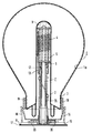
- This and other more detailed aspects of the invention are described and explained with reference to the drawing in which a lamp is shown partly in cross-section, partly in elevation.
- The electrodeless low-pressure discharge lamp has a
lamp vessel 1 which is closed in a vacuumtight manner, is made of, for example, lime glass, contains ionizable metal vapour and rare gas, and comprises acavity 2, for example of lead glass, at anend portion 3 of said vessel. - An
electric coil 4 around asleeve 5 of synthetic material is present in thecavity 2. Acore 6 of soft magnetic material is present in thesleeve 5 of synthetic material. A tube 7 containing liquid is present in thecore 6, projects to outside thecavity 2, and has a flange 8 there. - In the embodiment drawn, the
lamp vessel 1 contains a rare gas and mercury as an ionizable metal and is coated with a fluorescent powder 1a. - The
sleeve 5 is filled with anelastic polymer 9. The polymer fills the gap between the tube 7 and thecore 6. In the embodiment drawn, the polymer also envelops thesleeve 5. - The tube 7, the
core 6 and thesleeve 5 with thecoil 4 in the drawing together with thepolymer 9 form a sub-assembly which is provided as such in thecavity 2. Thesub-assembly cavity 2. Silicone rubber is used as thepolymer 9. - In the drawing, the
sleeve 5 is fastened with asnap connection support 14 of synthetic material which has aflange 15, on which arepresent hooks 16, at a free end. The flange 8 of the tube 7 and theflange 15 of thesupport 14 are fastened to one another and afoil 17 of synthetic material, for example silicone rubber, is provided against the flange 8. As a result, the lamp may be mounted against a metal support without the risk of a galvanic element being formed by this support and the flange 8. Acollar 19 of synthetic material, which is held by thehooks 16, is mounted to thelamp vessel 1, for example withsilicone compound 18. A cable leading to an electric supply may be connected tocontacts 20 at theflange 15, to which thecoil 4 is connected.
Claims (4)
- An electrodeless low-pressure discharge lamp comprising- a lamp vessel (1) which is sealed in a vacuumtight manner, contains ionizable metal vapour and rare gas, and has a cavity (2) at an end portion (3) of said vessel,- an electric coil (4) around a sleeve (5) of synthetic material in the cavity (2) of the lamp vessel (1),- a core (6) of soft magnetic material in the sleeve (5) of synthetic material,- a tube (7) containing a liquid in the core (6) of soft magnetic material, which tube (7) projects to outside the cavity (2) and has a flange (8) there,characterized in that
the sleeve (5) is at least substantially filled with an elastic polymer (9). - An electrodeless low-pressure discharge lamp as claimed in Claim 1, characterized in that the sleeve (5) is enveloped in the polymer (9).
- An electrodeless low-pressure discharge lamp as claimed in Claim 1 or 2, characterized in that the enveloped sleeve (5) with the coil (4), the core (6), and the tube (7) form a sub-assembly which is separate from the lamp vessel (1).
- An electrodeless low-pressure discharge lamp as claimed in Claim 1, 2 or 3, characterized in that the polymer (9) is silicone rubber.
Applications Claiming Priority (2)
| Application Number | Priority Date | Filing Date | Title |
|---|---|---|---|
| NL9100124 | 1991-01-25 | ||
| NL9100124 | 1991-01-25 |
Publications (3)
| Publication Number | Publication Date |
|---|---|
| EP0496464A2 true EP0496464A2 (en) | 1992-07-29 |
| EP0496464A3 EP0496464A3 (en) | 1993-06-23 |
| EP0496464B1 EP0496464B1 (en) | 1995-10-25 |
Family
ID=19858775
Family Applications (1)
| Application Number | Title | Priority Date | Filing Date |
|---|---|---|---|
| EP92200131A Expired - Lifetime EP0496464B1 (en) | 1991-01-25 | 1992-01-17 | Electrodeless low-pressure discharge lamp |
Country Status (8)
| Country | Link |
|---|---|
| US (1) | US5291091A (en) |
| EP (1) | EP0496464B1 (en) |
| JP (1) | JPH04308648A (en) |
| KR (1) | KR920015418A (en) |
| CN (1) | CN1028581C (en) |
| DE (1) | DE69205592T2 (en) |
| ES (1) | ES2079779T3 (en) |
| HU (1) | HU209221B (en) |
Cited By (4)
| Publication number | Priority date | Publication date | Assignee | Title |
|---|---|---|---|---|
| EP0577211A1 (en) * | 1992-07-03 | 1994-01-05 | Koninklijke Philips Electronics N.V. | Electroless low-pressure discharge lamp |
| EP0668605A2 (en) * | 1994-02-17 | 1995-08-23 | TUNGSRAM Részvénytársaság | Electrodeless low-pressure discharge lamp |
| US5572083A (en) * | 1992-07-03 | 1996-11-05 | U.S. Philips Corporation | Electroless low-pressure discharge lamp |
| US7205723B2 (en) | 2004-02-05 | 2007-04-17 | Matsushita Electric Industrial Co., Ltd. | Electrodeless discharge lamp |
Families Citing this family (10)
| Publication number | Priority date | Publication date | Assignee | Title |
|---|---|---|---|---|
| EP0551679A1 (en) * | 1992-01-07 | 1993-07-21 | Koninklijke Philips Electronics N.V. | Electrodeless low-pressure discharge lamp |
| ES2109425T3 (en) * | 1992-10-21 | 1998-01-16 | Koninkl Philips Electronics Nv | LIGHTING SET AND LOW PRESSURE DISCHARGE LAMP WITHOUT ELECTRODE SUITABLE FOR USE IN SUCH SET. |
| ES2110052T3 (en) * | 1992-10-21 | 1998-02-01 | Koninkl Philips Electronics Nv | LIGHTING EQUIPMENT AND LOW PRESSURE LAMP WITHOUT ELECTRODES SUITABLE FOR USE IN THIS LIGHTING EQUIPMENT. |
| GB9603197D0 (en) * | 1996-02-15 | 1996-04-17 | Gen Electric | Electrodeless discharge lamp |
| WO1997040518A1 (en) * | 1996-04-19 | 1997-10-30 | Philips Electronics N.V. | Electrodeless low-pressure discharge lamp |
| GB2314671A (en) * | 1996-06-26 | 1998-01-07 | Gen Electric | Electrodeless fluorescent lamp |
| WO1999018596A1 (en) * | 1997-10-07 | 1999-04-15 | Koninklijke Philips Electronics N.V. | Discharge lamp, comprising secondary side of piezotransformer as electrode |
| US6433478B1 (en) * | 1999-11-09 | 2002-08-13 | Matsushita Electric Industrial Co., Ltd. | High frequency electrodeless compact fluorescent lamp |
| US7064490B2 (en) * | 2002-07-02 | 2006-06-20 | Matsushita Electric Industrial Co., Ltd. | Compact self-ballasted electrodeless discharge lamp and electrodeless-discharge-lamp lighting device |
| EP1677339B1 (en) * | 2003-10-24 | 2013-01-09 | Panasonic Corporation | Electrodeless discharge lamp |
Citations (2)
| Publication number | Priority date | Publication date | Assignee | Title |
|---|---|---|---|---|
| DE3838121A1 (en) * | 1988-11-10 | 1990-05-17 | Vdo Schindling | Temperature sensor |
| EP0384520A1 (en) * | 1989-02-20 | 1990-08-29 | Koninklijke Philips Electronics N.V. | Electrodeless low-pressure discharge lamp |
Family Cites Families (2)
| Publication number | Priority date | Publication date | Assignee | Title |
|---|---|---|---|---|
| NL8104223A (en) * | 1981-09-14 | 1983-04-05 | Philips Nv | ELECTRESSLESS GAS DISCHARGE LAMP. |
| ES2075324T3 (en) * | 1990-04-06 | 1995-10-01 | Philips Electronics Nv | LOW PRESSURE DISCHARGE LAMP WITHOUT ELECTRODES. |
-
1992
- 1992-01-08 US US07/818,003 patent/US5291091A/en not_active Expired - Fee Related
- 1992-01-17 ES ES92200131T patent/ES2079779T3/en not_active Expired - Lifetime
- 1992-01-17 DE DE69205592T patent/DE69205592T2/en not_active Expired - Fee Related
- 1992-01-17 EP EP92200131A patent/EP0496464B1/en not_active Expired - Lifetime
- 1992-01-21 JP JP4031373A patent/JPH04308648A/en not_active Withdrawn
- 1992-01-21 KR KR1019920000790A patent/KR920015418A/en not_active Application Discontinuation
- 1992-01-22 HU HU9200205A patent/HU209221B/en not_active IP Right Cessation
- 1992-01-22 CN CN92100448A patent/CN1028581C/en not_active Expired - Fee Related
Patent Citations (2)
| Publication number | Priority date | Publication date | Assignee | Title |
|---|---|---|---|---|
| DE3838121A1 (en) * | 1988-11-10 | 1990-05-17 | Vdo Schindling | Temperature sensor |
| EP0384520A1 (en) * | 1989-02-20 | 1990-08-29 | Koninklijke Philips Electronics N.V. | Electrodeless low-pressure discharge lamp |
Cited By (5)
| Publication number | Priority date | Publication date | Assignee | Title |
|---|---|---|---|---|
| EP0577211A1 (en) * | 1992-07-03 | 1994-01-05 | Koninklijke Philips Electronics N.V. | Electroless low-pressure discharge lamp |
| US5572083A (en) * | 1992-07-03 | 1996-11-05 | U.S. Philips Corporation | Electroless low-pressure discharge lamp |
| EP0668605A2 (en) * | 1994-02-17 | 1995-08-23 | TUNGSRAM Részvénytársaság | Electrodeless low-pressure discharge lamp |
| EP0668605A3 (en) * | 1994-02-17 | 1997-03-26 | Tungsram Reszvenytarsasag | Electrodeless low-pressure discharge lamp. |
| US7205723B2 (en) | 2004-02-05 | 2007-04-17 | Matsushita Electric Industrial Co., Ltd. | Electrodeless discharge lamp |
Also Published As
| Publication number | Publication date |
|---|---|
| HUT60065A (en) | 1992-07-28 |
| EP0496464B1 (en) | 1995-10-25 |
| DE69205592D1 (en) | 1995-11-30 |
| CN1028581C (en) | 1995-05-24 |
| JPH04308648A (en) | 1992-10-30 |
| DE69205592T2 (en) | 1996-05-30 |
| CN1063580A (en) | 1992-08-12 |
| US5291091A (en) | 1994-03-01 |
| HU9200205D0 (en) | 1992-04-28 |
| EP0496464A3 (en) | 1993-06-23 |
| ES2079779T3 (en) | 1996-01-16 |
| HU209221B (en) | 1994-03-28 |
| KR920015418A (en) | 1992-08-26 |
Similar Documents
| Publication | Publication Date | Title |
|---|---|---|
| EP0496464B1 (en) | Electrodeless low-pressure discharge lamp | |
| KR100198038B1 (en) | Electroless low-pressure discharge lamp | |
| CN1029181C (en) | Electrodeless low-pressure discharge lamp | |
| EP2156463B1 (en) | Compact fluorescent lamp with outer envelope and method for manufacturing such lamp | |
| US4536675A (en) | Electrodeless gas discharge lamp having heat conductor disposed within magnetic core | |
| EP0207333A1 (en) | Electrodeless high pressure sodium iodide arc lamp | |
| EP0671758A2 (en) | Electrodeless high intensity discharge lamp | |
| US4571526A (en) | Low-pressure discharge lamp with cooled internal ballast | |
| JP2005150108A (en) | Non-electrode fluorescent lamp | |
| US5086249A (en) | Compact discharge lamp unit and method for manufacturing same | |
| US4262231A (en) | Helical wire coil in solenoidal lamp tip-off region wetted by alloy forming an amalgam with mercury | |
| JP2006147572A (en) | Electrodeless fluorescent lamp with controlled cold spot temperature | |
| US4927217A (en) | Electrodeless low-pressure discharge lamp | |
| US5572083A (en) | Electroless low-pressure discharge lamp | |
| EP1868227A1 (en) | Electrodeless discharge lamp and illuminator comprising it | |
| EP0551679A1 (en) | Electrodeless low-pressure discharge lamp | |
| US4528209A (en) | Use of amalgams in solenoidal electric field lamps | |
| US7088056B2 (en) | Bulb type electrodeless fluorescent lamp | |
| KR100275355B1 (en) | Electrodeless low-pressure discharge lamp | |
| US5258683A (en) | Electrodeless low-pressure discharge lamp | |
| US4499400A (en) | Use of amalgams in solenoidal electric field lamps | |
| US6201347B1 (en) | Low-pressure discharge lamp | |
| EP0440300B1 (en) | Electrodeless low-pressure discharge lamp | |
| EP0577211B1 (en) | Electroless low-pressure discharge lamp | |
| EP1298702B1 (en) | Amalgam retainer |
Legal Events
| Date | Code | Title | Description |
|---|---|---|---|
| PUAI | Public reference made under article 153(3) epc to a published international application that has entered the european phase |
Free format text: ORIGINAL CODE: 0009012 |
|
| AK | Designated contracting states |
Kind code of ref document: A2 Designated state(s): BE DE ES FR GB IT NL |
|
| PUAL | Search report despatched |
Free format text: ORIGINAL CODE: 0009013 |
|
| AK | Designated contracting states |
Kind code of ref document: A3 Designated state(s): BE DE ES FR GB IT NL |
|
| 17P | Request for examination filed |
Effective date: 19931213 |
|
| 17Q | First examination report despatched |
Effective date: 19941213 |
|
| GRAA | (expected) grant |
Free format text: ORIGINAL CODE: 0009210 |
|
| AK | Designated contracting states |
Kind code of ref document: B1 Designated state(s): BE DE ES FR GB IT NL |
|
| PG25 | Lapsed in a contracting state [announced via postgrant information from national office to epo] |
Ref country code: NL Free format text: LAPSE BECAUSE OF FAILURE TO SUBMIT A TRANSLATION OF THE DESCRIPTION OR TO PAY THE FEE WITHIN THE PRESCRIBED TIME-LIMIT Effective date: 19951025 Ref country code: BE Effective date: 19951025 |
|
| REF | Corresponds to: |
Ref document number: 69205592 Country of ref document: DE Date of ref document: 19951130 |
|
| ITF | It: translation for a ep patent filed |
Owner name: ING. C. GREGORJ S.P.A. |
|
| REG | Reference to a national code |
Ref country code: ES Ref legal event code: FG2A Ref document number: 2079779 Country of ref document: ES Kind code of ref document: T3 |
|
| PG25 | Lapsed in a contracting state [announced via postgrant information from national office to epo] |
Ref country code: ES Free format text: LAPSE BECAUSE OF NON-PAYMENT OF DUE FEES Effective date: 19960118 |
|
| PG25 | Lapsed in a contracting state [announced via postgrant information from national office to epo] |
Ref country code: GB Effective date: 19960125 |
|
| PGFP | Annual fee paid to national office [announced via postgrant information from national office to epo] |
Ref country code: BE Payment date: 19960129 Year of fee payment: 5 |
|
| ET | Fr: translation filed | ||
| NLV1 | Nl: lapsed or annulled due to failure to fulfill the requirements of art. 29p and 29m of the patents act | ||
| PLBE | No opposition filed within time limit |
Free format text: ORIGINAL CODE: 0009261 |
|
| STAA | Information on the status of an ep patent application or granted ep patent |
Free format text: STATUS: NO OPPOSITION FILED WITHIN TIME LIMIT |
|
| GBPC | Gb: european patent ceased through non-payment of renewal fee |
Effective date: 19960125 |
|
| PG25 | Lapsed in a contracting state [announced via postgrant information from national office to epo] |
Ref country code: FR Effective date: 19960930 |
|
| PG25 | Lapsed in a contracting state [announced via postgrant information from national office to epo] |
Ref country code: DE Effective date: 19961001 |
|
| 26N | No opposition filed | ||
| REG | Reference to a national code |
Ref country code: FR Ref legal event code: ST |
|
| REG | Reference to a national code |
Ref country code: ES Ref legal event code: FD2A Effective date: 19990503 |
|
| PG25 | Lapsed in a contracting state [announced via postgrant information from national office to epo] |
Ref country code: IT Free format text: LAPSE BECAUSE OF NON-PAYMENT OF DUE FEES Effective date: 20050117 |