EP0497781B1 - Einführvorrichtung für schlauchförmige fiberoptische instrumente, insbes. kolonoskope - Google Patents
Einführvorrichtung für schlauchförmige fiberoptische instrumente, insbes. kolonoskope Download PDFInfo
- Publication number
- EP0497781B1 EP0497781B1 EP90913154A EP90913154A EP0497781B1 EP 0497781 B1 EP0497781 B1 EP 0497781B1 EP 90913154 A EP90913154 A EP 90913154A EP 90913154 A EP90913154 A EP 90913154A EP 0497781 B1 EP0497781 B1 EP 0497781B1
- Authority
- EP
- European Patent Office
- Prior art keywords
- wall
- support elements
- intermediate space
- inserting means
- colonoscope
- Prior art date
- Legal status (The legal status is an assumption and is not a legal conclusion. Google has not performed a legal analysis and makes no representation as to the accuracy of the status listed.)
- Expired - Lifetime
Links
Images


Classifications
-
- A—HUMAN NECESSITIES
- A61—MEDICAL OR VETERINARY SCIENCE; HYGIENE
- A61B—DIAGNOSIS; SURGERY; IDENTIFICATION
- A61B1/00—Instruments for performing medical examinations of the interior of cavities or tubes of the body by visual or photographical inspection, e.g. endoscopes; Illuminating arrangements therefor
- A61B1/31—Instruments for performing medical examinations of the interior of cavities or tubes of the body by visual or photographical inspection, e.g. endoscopes; Illuminating arrangements therefor for the rectum, e.g. proctoscopes, sigmoidoscopes, colonoscopes
-
- A—HUMAN NECESSITIES
- A61—MEDICAL OR VETERINARY SCIENCE; HYGIENE
- A61B—DIAGNOSIS; SURGERY; IDENTIFICATION
- A61B1/00—Instruments for performing medical examinations of the interior of cavities or tubes of the body by visual or photographical inspection, e.g. endoscopes; Illuminating arrangements therefor
- A61B1/00064—Constructional details of the endoscope body
- A61B1/00071—Insertion part of the endoscope body
- A61B1/00078—Insertion part of the endoscope body with stiffening means
-
- A—HUMAN NECESSITIES
- A61—MEDICAL OR VETERINARY SCIENCE; HYGIENE
- A61B—DIAGNOSIS; SURGERY; IDENTIFICATION
- A61B1/00—Instruments for performing medical examinations of the interior of cavities or tubes of the body by visual or photographical inspection, e.g. endoscopes; Illuminating arrangements therefor
- A61B1/00131—Accessories for endoscopes
- A61B1/00135—Oversleeves mounted on the endoscope prior to insertion
-
- A—HUMAN NECESSITIES
- A61—MEDICAL OR VETERINARY SCIENCE; HYGIENE
- A61B—DIAGNOSIS; SURGERY; IDENTIFICATION
- A61B1/00—Instruments for performing medical examinations of the interior of cavities or tubes of the body by visual or photographical inspection, e.g. endoscopes; Illuminating arrangements therefor
- A61B1/00147—Holding or positioning arrangements
- A61B1/00154—Holding or positioning arrangements using guiding arrangements for insertion
-
- A—HUMAN NECESSITIES
- A61—MEDICAL OR VETERINARY SCIENCE; HYGIENE
- A61B—DIAGNOSIS; SURGERY; IDENTIFICATION
- A61B1/00—Instruments for performing medical examinations of the interior of cavities or tubes of the body by visual or photographical inspection, e.g. endoscopes; Illuminating arrangements therefor
- A61B1/273—Instruments for performing medical examinations of the interior of cavities or tubes of the body by visual or photographical inspection, e.g. endoscopes; Illuminating arrangements therefor for the upper alimentary canal, e.g. oesophagoscopes, gastroscopes
- A61B1/2736—Gastroscopes
-
- A—HUMAN NECESSITIES
- A61—MEDICAL OR VETERINARY SCIENCE; HYGIENE
- A61M—DEVICES FOR INTRODUCING MEDIA INTO, OR ONTO, THE BODY; DEVICES FOR TRANSDUCING BODY MEDIA OR FOR TAKING MEDIA FROM THE BODY; DEVICES FOR PRODUCING OR ENDING SLEEP OR STUPOR
- A61M25/00—Catheters; Hollow probes
- A61M25/01—Introducing, guiding, advancing, emplacing or holding catheters
-
- A—HUMAN NECESSITIES
- A61—MEDICAL OR VETERINARY SCIENCE; HYGIENE
- A61B—DIAGNOSIS; SURGERY; IDENTIFICATION
- A61B1/00—Instruments for performing medical examinations of the interior of cavities or tubes of the body by visual or photographical inspection, e.g. endoscopes; Illuminating arrangements therefor
- A61B1/012—Instruments for performing medical examinations of the interior of cavities or tubes of the body by visual or photographical inspection, e.g. endoscopes; Illuminating arrangements therefor characterised by internal passages or accessories therefor
- A61B1/015—Control of fluid supply or evacuation
-
- A—HUMAN NECESSITIES
- A61—MEDICAL OR VETERINARY SCIENCE; HYGIENE
- A61B—DIAGNOSIS; SURGERY; IDENTIFICATION
- A61B17/00—Surgical instruments, devices or methods, e.g. tourniquets
- A61B17/00234—Surgical instruments, devices or methods, e.g. tourniquets for minimally invasive surgery
- A61B2017/00287—Bags for minimally invasive surgery
-
- A—HUMAN NECESSITIES
- A61—MEDICAL OR VETERINARY SCIENCE; HYGIENE
- A61M—DEVICES FOR INTRODUCING MEDIA INTO, OR ONTO, THE BODY; DEVICES FOR TRANSDUCING BODY MEDIA OR FOR TAKING MEDIA FROM THE BODY; DEVICES FOR PRODUCING OR ENDING SLEEP OR STUPOR
- A61M25/00—Catheters; Hollow probes
- A61M25/0021—Catheters; Hollow probes characterised by the form of the tubing
- A61M25/0023—Catheters; Hollow probes characterised by the form of the tubing by the form of the lumen, e.g. cross-section, variable diameter
- A61M25/0026—Multi-lumen catheters with stationary elements
- A61M2025/0039—Multi-lumen catheters with stationary elements characterized by lumina being arranged coaxially
-
- A—HUMAN NECESSITIES
- A61—MEDICAL OR VETERINARY SCIENCE; HYGIENE
- A61M—DEVICES FOR INTRODUCING MEDIA INTO, OR ONTO, THE BODY; DEVICES FOR TRANSDUCING BODY MEDIA OR FOR TAKING MEDIA FROM THE BODY; DEVICES FOR PRODUCING OR ENDING SLEEP OR STUPOR
- A61M25/00—Catheters; Hollow probes
- A61M25/0043—Catheters; Hollow probes characterised by structural features
- A61M25/0054—Catheters; Hollow probes characterised by structural features with regions for increasing flexibility
Definitions
- insertion devices are furthermore used which have a one-piece sliding tube which has a high bending stiffness in comparison with the associated colonoscope, which permits only relatively slight elastic deflections.
- the inside diameter of such a sliding tube for a colonoscope with an outside diameter of 15 mm is, for example, almost 16 mm, so that the colonoscope can be easily pushed through at any time.
- the outer diameter of the guide tube is, for example, 19 mm.
- the insertion part is 40 cm long; the length of the associated colonoscope is usually between 130 and 180 cm.
- a distal end region of about 10 cm in length of the colonoscope can usually be moved in four directions (up / down and left / right) by means of adjusting wheels mounted on the proximal end.
- the examining or treating doctor inserts the colonoscope into the colon from the anus.
- the colonoscope In order for a complete examination of the colon to be possible, the colonoscope must be advanced to the coecum. The direction of movement of the colonoscope with its movable distal end area can be determined. Nevertheless, the bends of the colon, namely the sigmoid and especially the two colonic flexures, regularly result in problems with the risk of injury, pain for the patient and cramp-like contractions of the colon up to the point of being unable to continue the examination. These problems are related to the fact that the colon is soft and only relatively little attached to the abdomen.
- a mechanical-pneumatic manipulation system for colonoscopes in which the insertion of a colonoscope for the doctor and patient is to be facilitated with an insertion device.
- This insertion device also includes a flexible sliding tube into which the colonoscope can be inserted.
- a balloon or a group of balloons made of highly flexible material is arranged on the sliding tube. When deflated, the balloon or the group of balloons lies firmly against the sliding tube; in the inflated state, the balloon or group of balloons should be supported in the vicinity, i.e. on the inner wall of the intestine, and the shaft of the colonoscope should be able to be moved forward or back with the aid of a mechanism.
- a second group of balloons which is fixedly mounted on the colonoscope shaft, is deflated when the colonoscope is to be moved relative to the sliding tube supported in the vicinity, and is inflated when the sliding tube is to be moved together with its balloon or balloon group.
- the guide tube has longitudinal channels, one of which is intended to accommodate pressure and vacuum lines and another to accommodate a mechanical pull and push system.
- This known insertion device with an inflatable balloon or a group of such balloons arranged outside cannot significantly facilitate the insertion of a colonoscope into a human intestine, since the intestine undergoes any stretching, regardless of whether it is from an unprotected one Colonoscope or from one or more inflated balloons is reacted in the same way with spastic, painful contractions. Such contractions also occur distal to the colonoscope and complicate its further forward movement.
- the known insertion device is not suitable for non-medical examination objects, such as machine parts, which can have sharp-edged inner contours because of the sensitivity of a balloon arrangement to the flexible sliding tube to injury.
- a device for transporting a colonoscope known from DE 2823025 C2, in which the distal end of the colonoscope is connected by a thin, inverted tube to the distal end of a conical tube which can be inserted into the human anal ring.
- a housing which encloses the colonoscope and has a connecting piece, can be screwed onto the proximal end of the tube. If a pressure medium is introduced through the connecting piece, a section of the tube lying between the two tube ends is pushed into the large intestine, whereby it turns out and pulls the colonoscope with it. This should be moved into the intestine by pulling and not by thrust.
- the inner part of the tube should be turned inside out so that it then forms an outer tube part that does not move relative to the intestinal mucosa.
- this can also cause painful spastic intestinal contractions.
- this known device succeeds in advancing a colonoscope sufficiently far, in particular as far as the coecum, it is not possible to leave the tube in the intestine and to use it as an aid for reinserting the colonoscope, for example for removal one larger polyps, has been temporarily removed.
- the reversible and therefore necessarily thin tube is not suitable for technical applications, since it can easily tear on sharp edges and protrusions of the examination object.
- the invention is based on the object of designing an insertion device for tubular fiber-optical instruments, in particular colonoscopes, gastroscopes and the like, in such a way that it considerably facilitates the complete and, if necessary, multiple insertion of such an instrument up to the end of the object to be examined and in medical examinations for the Makes patients more bearable and simplified for the doctor.
- the object is achieved based on an insertion device of the type described in the introduction in that a part of the support body is fixedly arranged on the outside of the inner wall and the rest of the support body is fixedly arranged on the inside of the outer wall.
- the support body can warts, spirals, ribs or the like. be.
- the fixed arrangement of the support body can result from one-piece production of the support body with the associated inner or outer wall or by gluing, melting or vulcanizing separately manufactured support bodies.
- the inner and outer walls together form a slide-in part which can be stiffened in any bend, for example adapted to the sigmoid and even to the two colonic flexures, by evacuating the space to such an extent that the support members of the inner wall rest against those of the outer wall.
- a fiber-optic instrument, in particular a colonoscope can be inserted relatively easily through the insert part deformed and fixed in this way. If a fluid is then introduced into the intermediate space again, the insert part regains its original flexibility.
- the inner wall can preferably be deformed radially inward by fluid introduced into the intermediate space and can therefore be placed against a lateral surface of a fiber-optical instrument, in particular a colonoscope, which is guided through the insertion device.
- a fluid under pressure for example compressed air
- the inner wall of the insertion part can thus be pressed firmly against an instrument, in particular a colonoscope, which is passed through the insertion device without the outer wall being inflated.
- the insertion device is still flexible and can be advanced together with the fiber-optic instrument because of its temporarily fixed connection.
- the end of the examination area for example the coecum, can be easily reached by alternately pushing the instrument alone and the instrument with an insertion device.
- a particularly strong mutual toothing and thus high bending stiffness of the evacuated insert part results when the support bodies, which are arranged on the outside of the inner wall, engage in a gap between the supporting bodies on the inside of the outer wall.
- the space can be divided into several chambers, which can be evacuated individually or together and can be pressurized if necessary.
- Such chambers can be separated from one another, for example, by weld seams or other seams which connect the inner wall to the outer wall in the manner of quilted seams.
- the chambers can extend in a straight line or helically along the insertion part.
- the inside and outside wall can form uniform wall areas between the chambers.
- the support bodies fixedly arranged on the inner wall of the insert part are designed in the form of a sleeve and engage in two adjacent sleeve-shaped support bodies which are fixedly arranged on the outer wall of the insert part.
- the insert part can be stiffened particularly effectively by evacuating the space between its inner wall and its outer wall.
- the embodiment described above can be further developed in that the support bodies arranged on the inner wall are designed to be radially expandable and compressible by slots over part of their axial length. This ensures that the slotted support bodies arranged on the inner wall nestle well against the support bodies of the outer wall during evacuation. Such slots also make it possible to bend the insert part around particularly tight radii.
- the support bodies arranged on the outer wall each have an inextensible annular bead at their two ends, which overlaps the slots of the two adjacent support bodies only over part of their axial length, so that all parts of the intermediate space are in any position of the insertion part are interconnected by at least part of the slots.
- Such ring beads also have the advantage that they counteract any tendency of the outer wall to inflate if there is overpressure in the space between the inner and outer wall.
- the stiffening of the insert part in the case of an evacuated intermediate space can also be supported in that the support bodies arranged on the inner wall have a corrugation on the outside and in that the support bodies arranged on the outer wall are corrugated on the inside in a corresponding manner.
- the corrugations which are thus radially opposite one another, engage in one another when the intermediate space is evacuated, so that the insert part is positively fixed in the position which it occupied immediately before the intermediate space was evacuated.
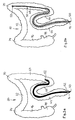
- the main components of the insertion device 10 shown in FIGS. 1 and 2 are a handle part 12 and an insertion part 14.
- the insertion part 14 includes an inner wall 16, an outer wall 18, an annular space 20 formed between them, a distal end region 22 and finally a distal guide ring 24
- the inner wall 16 is tightly connected to the outer wall 18 on the handle part 12 and on the distal end region 22, as a result of which the intermediate space 20 is closed.
- Inner wall 16 and outer wall 18 can, for example, be vulcanized, glued and / or tightly clamped onto the associated sleeve 26 or 28.
- the two sleeves 26 and 28 are tightly connected to one another in their proximal end region, for example screwed.
- connection 30 for introducing and sucking a fluid into and out of the intermediate space 20.
- a mechanical seal is expediently arranged, which seals against the associated fiber-optic instrument.
- the interior of the Inner sleeve 26 can open an additional suction and / or flushing line so that air or secretion can be sucked out of a examined body part or a flushing liquid can be introduced through the insertion device.
- Inner wall 16 and outer wall 18 are each formed by a tubular film made of flexible, body-compatible plastic.
- the inner wall 16 has a smaller thickness than the outer wall 18 and can therefore also be easily deformed radially inward if an excess pressure is generated in the intermediate space 20;
- the outer wall 18, on the other hand, is so firm and possibly reinforced with fibers that it cannot be inflated by a pressure prevailing in the intermediate space 20, which already noticeably deforms the inner wall 16.
- support bodies 32 are arranged uniformly distributed on the outside of the inner wall 16; gaps 34 are left between them.
- support bodies 36 and gaps 38 are arranged on the inside of the outer wall 18 such that each support body 32 is radially opposite a gap 38 and each support body 36 is opposite a gap 34.
- the support bodies 32 and 36 do not touch one another or at most loosely. This state is shown in Fig. 2.
- each support body 32 engages in a gap 38 and each support body 36 engages in a gap 34.
- the insertion part 14 is stiffened in any shape that it had occupied before the evacuation .
- connection 30 is connected via a hose 40 to a control device 42 of a conventional type, for example by actuating a rocker-type switch 44, the hose 40 is optionally connected to a compressed air line 46 or a vacuum line 48.
- a commercially available colonoscope 50 is inserted with its distal end 52 first into the proximal end of the guide tube 10 and pushed through its grip part 12 and insertion part 14.
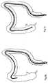
- the further handling of the insertion device 10 and the colonoscope 50 takes place on the patient and is shown in FIGS. 3a to 3f.
- the common representation of the insertion part 14 and the colonoscope 50 as a thick line means that air (or another fluid) with excess pressure has been introduced into the intermediate space 20 and the inner wall 16 has thereby been firmly applied to the colonoscope 50; the insertion part 14 is then just as flexible as the colonoscope 50.
- the representation of the insertion part 14 as a thin line pair which can be distinguished from the colonoscope 50, on the other hand, means that there is a negative pressure in the insertion part 14, in which the inner wall 16 releases the colonoscope 50 for relative displacements and firmly on the outer wall 18 abuts so that the insertion part 14 is stiffened.
- the colonoscope 50 is inserted into the colon 60 with the flexible insert part 14 firmly attached to it, first from the anus 62 through the rectum 64 to the transition from the sigmoid 66 to the descending colon 68. In this position, the insert part becomes 14 stiffened by evacuating its space 20.
- the endoscope 50 is pushed further through the insertion device 10 with stiffened insertion part 14 to the left colon flexure 70.
- the stiffening of the insert part 14 is released again by introducing compressed air into its intermediate space 20; the sigmoid 66 is straightened somewhat and the insertion part 14 is pushed up to the left colon flexure 70.
- the insertion part 14 is stiffened again and the colonoscope 50 is pushed through the left colon flexure 70.
- the stiffening of the insert part 14 is released again; the insertion part 14 is pushed in beyond the right colon flexure 74 and then stiffened again, so that the colonoscope 50 can now be pushed further into the coecum 78.
- the colonoscope 50 can be pulled out completely, for example in order to transport a tumor which has been removed with a loop and which cannot be removed through the colonoscope 50 to the outside. Subsequently, the colonoscope 50 can be reinserted through the insertion device 10, which remains in the stiffened state in the colon 60, and, if necessary, further tumors can be removed and transported to the outside.
- annular or sleeve-shaped support bodies 32 are arranged on the outside of the inner wall 16, and are fastened to the inner wall 16 with an annular weld or adhesive 82 arranged centrally on them.
- Each of the support bodies 32 has axially parallel slots 84 extending from its two end faces, each of which extends over almost half the axial width of the support body 32.
- the slots 84 are so wide that the annular support bodies 32 can be compressed radially in their end regions and can also be widened.
- annular or sleeve-shaped support bodies 36 are arranged and also fastened to the outer wall 18 with an annular weld or adhesive 86 arranged centrally on them.
- Each of the support bodies 32 axially engages in two adjacent support bodies 36; in a corresponding manner, each of the support bodies 36 overlaps the two adjacent support bodies 32 on a part, e.g. about a third of their axial length.
- the support bodies 36 are not slotted, but are provided at their two ends with an annular bead 88, which is not or only slightly stretchable.
- the support bodies 32 each have a spherical outside with a corrugation 90; the support bodies 36 are formed in a complementary manner on the inside of their annular beads 88 and are provided with a corresponding corrugation 92.
- the corrugations 90 and 92 of overlapping support bodies 32 and 36 interlock and fix the support bodies in the position which they assumed at the beginning of the evacuation.
- the slots 84 form longitudinal channels that are therefor ensure that the space 20 between the inner wall 16 and the outer wall 18 can be evacuated without difficulty over the entire length of the insertion part 14.
- the interlocking corrugations 90 and 92 give the insert part 14, in the evacuated state of its intermediate space 20, a stiffness that is many times greater than the very low stiffness of the inner wall 16 and the outer wall 18. Such stiffening can be in any bent state achieve the insertion part 14.
Abstract
Description
- Die Erfindung betrifft eine Einführvorrichtung für schlauchförmige fiberoptische Instrumente, insbes. Kolonoskope, Gastroskope und dgl. mit einem Griffteil und einem in ein Untersuchungsobjekt, insbes. menschliches Kolon, einschiebbaren, biegsamen Einschubteil, der zwischen einer Innenwand und einer Außenwand mindestens einen nach außen abgedichteten Zwischenraum aufweist, in den sich ein Fluid einleiten läßt, wobei
- die Außenwand des Einschubteils von einem flexiblen, jedoch vom Fluid im Zwischenraum nicht ballonartig aufblähbaren Schlauch gebildet ist,
- die Innenwand des Einschubteils ebenfalls von einem Schlauch gebildet ist, und
- der Zwischenraum Stützkörper enthält, über die sich die Innenwand und die Außenwand aneinander abstützen, wenn der Druck im Zwischenraum einen vorbestimmten Betrag unterschreitet.
- Eine Einführvorrichtung dieser Gattung ist aus der US 4815450 bekannt. Dort enthält der Zwischenraum zwischen Innen- und Außenwand des Einschubteils kugelförmige Stützkörper, die lose angeordnet und somit in dem Zwischenraum beweglich sind. Das hat zur Folge, daß die Stützkörper im Zwischenraum verrutschen können und deshalb ihren Zweck, das Einschubteil zu versteifen, wenn im Zwischenraum ein Vakuum herrscht, nicht immer zuverlässig erfüllen. Somit kann der Benutzer sich nicht darauf verlassen, daß die Einführvorrichtung eine bestimmte gewünschte Form während einer bestimmten Handhabung eines Kolonoskops od.dgl. beibehält.
- Schlauchförmige fiberoptische Instrumente haben, wie z.B. aus der US 4696544 bekannt ist, Anwendungsgebiete auch außerhalb der Medizin, beispielsweise zum Untersuchen von Rohrleitungen, Gefäßen und Maschinenteilen. Entsprechend ist auch der Begriff Untersuchungsobjekt im Rahmen der vorliegenden Erfindung zu verstehen.
- Zum Einführen von Kolonoskopen sind ferner Einführvorrichtungen in Gebrauch, die ein einstückiges Gleitrohr von einer im Vergleich zum zugehörigen Kolonoskop hohen Biegesteifigkeit aufweisen, die nur verhältnismäßig geringfügige elastische Verbiegungen zuläßt. Der Innendurchmesser eines solchen Gleitrohrs für ein Kolonoskop mit 15 mm Außendurchmesser beträgt beispielsweise knapp 16 mm, so daß sich das Kolonoskop jederzeit leicht hindurchschieben läßt. Der Außendurchmesser des Gleitrohrs beträgt beispielsweise 19 mm. Der Einschubteil ist 40 cm lang; die Länge des zugehörigen Kolonoskops liegt üblicherweise zwischen 130 und 180 cm. Ein distaler Endbereich von etwa 10 cm Länge des Kolonoskops läßt sich mittels am proximalen Ende gelagerter Stellräder üblicherweise in vier Richtungen (oben/unten und links/rechts) bewegen.
- Das Kolonoskop wird vom untersuchenden oder behandelnden Arzt vom Anus aus in das Kolon eingeführt. Damit eine vollständige Untersuchung des Kolons möglich ist, muß das Kolonoskop bis zum Coecum vorgeschoben werden. Dabei läßt sich die Bewegungsrichtung des Kolonoskops mit dessen beweglichem distalen Endbereich bestimmen. Dennoch ergeben sich an den Biegungen des Kolons, nämlich am Sigmoid und besonders an den beiden Kolonflexuren, regelmäßig Probleme mit Verletzungsgefahren, Schmerzen für den Patienten und krampfartigen Kontraktionen des Kolons bis hin zur Unmöglichkeit, die Untersuchung forzusetzen. Diese Probleme hängen damit zusammen, daß das Kolon weich ist und nur relativ wenig im Bauchraum befestigt ist. Die Hauptrichtung der Kraft, mit der das Kolonoskop vorgeschoben wird, verläuft nach einer Umlenkung nicht mehr in Richtung zum distalen Ende des Kolonoskops, sondern auf die leicht nachgebende Wand des Kolons, was für den Patienten unangenehm ist. In etwa 10 bis 15 % aller Fälle kann deshalb des Coecum nicht erreicht werden.
- Diese Schwierigkeiten lassen sich mit den gebräuchlichen Einführvorrichtungen nur teilweise überwinden, da sie das Kolonoskop nur durch das Rektum und allenfalls noch das Sigmoid und das Kolon descendens zu führen vermögen. Spätestens an der linken Kolonflexur bleiben aber die beschriebenen Probleme bestehen. Außerdem wird es von vielen Patienten schon als unangenehm empfunden, daß dem Sigmoid von dem Gleitrohr ein nahezu geradliniger Verlauf aufgezwungen wird, da die Form des Gleitrohrs nicht willkürlich veränderbar ist. Wegen der hohen Steifigkeit des Gleitrohrs besteht bei unachtsamer Handhabung die Gefahr, daß das Kolon perforiert wird.
- Aus der DE 3605169 A1 ist ein mechanisch-pneumatisches Manipulationssystem für Kolonoskope bekannt, bei dem mit einer Einführvorrichtung das Einführen eines Kolonoskops für Arzt und Patient erleichtert werden soll. Auch zu dieser Einführvorrichtung gehört ein flexibles Gleitrohr, in das sich das Kolonoskop einschieben läßt. Auf dem Gleitrohr ist ein Ballon oder eine Ballongruppe aus hochflexiblem Material angeordnet. Der Ballon oder die Ballongruppe liegt in entlüftetem Zustand fest an dem Gleitrohr an; in aufgeblasenem Zustand soll sich der Ballon oder die Ballongruppe in der Umgebung, also an der Darminnenwand, abstützen und dabei soll der Schaft des Kolonoskops mit Hilfe einer Mechanik vor- oder zurückbewegt werden können. Eine zweite Ballongruppe, die auf dem Kolonoskopschaft fest montiert ist, wird entlüftet, wenn das Kolonoskop gegenüber dem in der Umgebung abgestützten Gleitrohr verschoben werden soll, und wird aufgeblasen, wenn das Gleitrohr zusammen mit dessen Ballon oder Ballongruppe verschoben werden soll. Das Gleitrohr weist Längskanäle auf, von denen einer Druck- und Vakuumleitungen und ein anderer ein mechanisches Zug- und Schubsystem aufnehmen soll.
- Diese bekannte Einführvorrichtung mit einem außen angeordneten aufblasbaren Ballon oder einer Gruppe solcher Ballons kann das Einführen eines Kolonoskops in einen menschlichen Darm nicht wesentlich erleichtern, da der Darm auf jede Dehnung, unabhängig davon, ob sie von einem ungeschützten Kolonoskop oder von einem oder mehreren aufgeblasenen Ballons hervorgerufen wird, in gleicher Weise mit spastischen, schmerzhaften Kontraktionen reagiert. Solche Kontraktionen treten auch distal des Kolonoskops auf und erschweren dessen weitere Vorwärtsbewegung. Für nicht medizinische Untersuchungsobjekte, wie beispielsweise Maschinenteile, die scharfkantige Innenkonturen haben können, eignet sich die bekannte Einführvorrichtung wegen der Verletzungsempfindlichkeit einer Ballonanordnung auf dem flexiblen Gleitrohr nicht.
- Entsprechendes gilt auch für eine aus der DE 2823025 C2 bekannte Vorrichtung zum Transport eines Kolonoskops, bei dem das distale Ende des Kolonoskops durch einen dünnen, umgestülpten Schlauch mit dem distalen Ende eines konusförmigen Rohrs verbunden ist, das in den menschlichen Analring einführbar ist. Auf das proximale Ende des Rohrs ist ein Gehäuse aufschraubbar, welches das Kolonoskop umschließt und einen Anschlußstutzen aufweist. Wird durch den Anschlußstutzen ein Druckmedium eingeleitet, dann wird ein zwischen den beiden Schlauchenden liegender Abschnitt des Schlauchs in den Dickdarm hineingeschoben, wobei er sich ausstülpt und das Kolonoskop mit sich zieht. Dieses soll also durch Zug und nicht durch Schub in den Darm hineinbewegt werden. Beim Vordringen des Schlauchs soll dessen innerer Teil sich fortlaufend umstülpen, so daß er dann einen äußeren Schlauchteil bildet, der sich gegenüber der Darmschleimhaut nicht bewegt. Auch dadurch können jedoch schmerzhafte spastische Darmkontraktionen hervorgerufen werden. Selbst wenn es mit dieser bekannten Vorrichtung gelingt, ein Kolonoskop genügend weit, insbesondere bis zum Coecum vorzuschieben, ist es jedenfalls nicht möglich, den Schlauch im Darm zurückzulassen und ihn als Hilfe für ein erneutes Einführen des Kolonoskops zu verwenden, wenn dieses, beispielsweise zum Entfernen eines größeren Polypen, vorübergehend herausgezogen worden ist. Für technische Anwendungen eignet sich der umstülpbare und deshalb notwendigerweise dünne Schlauch nicht, da er an scharfen Kanten und Vorsprüngen des Untersuchungsobjekts leicht zerreißen kann.
- Der Erfindung liegt die Aufgabe zugrunde, eine Einführvorrichtung für schlauchförmige fiberoptische Instrumente, insbes. Kolonoskope, Gastroskope und dgl. derart zu gestalten, daß sie das vollständige und nötigenfalls mehrfache Einführen eines solchen Instruments bis zum Ende des Untersuchungsobjekts wesentlich erleichtert und bei medizinischen Untersuchungen für den Patienten erträglicher macht und für den Arzt vereinfacht.
- Die Aufgabe ist erfindungsgemäß ausgehend von einer Einführvorrichtung der eingangs beschriebenen Gattung dadurch gelöst, daß ein Teil der Stützkörper an der Außenseite der Innenwand fest angeordnet und der Rest der Stützkörper an der Innenseite der Außenwand fest angeordnet ist.
- Die Stützkörper können Warzen, Wendeln, Rippen od.dgl. sein. Die feste Anordnung der Stützkörper kann sich durch einstückige Herstellung der Stützkörper mit der zugehörigen Innen- bzw. Außenwand oder durch Ankleben, Anschmelzen oder Anvulkanisieren gesondert hergestellter Stützkörper ergeben. Innen- und Außenwand bilden zusammen ein Einschubteil, das sich in beliebiger, z.B. an das Sigmoid und sogar an die beiden Kolonflexuren angepaßter Biegung versteifen läßt, indem man den Zwischenraum soweit evakuiert, daß die Stützkörper der Innenwand an denen der Außenwand anliegen. Durch das so verformte und fixierte Einschubteil läßt sich ein fiberoptisches Instrument, insbes. Kolonoskop, verhältnismäßig leicht einführen. Wird dann in den Zwischenraum wieder ein Fluid eingeleitet, so gewinnt der Einschubteil seine ursprüngliche Flexibilität zurück.
- Die Innenwand ist vorzugsweise durch in den Zwischenraum eingeleitetes Fluid radial nach innen verformbar und dadurch an eine Mantelfläche eines durch die Einführvorrichtung hindurchgeführten fiberoptischen Instruments, insbes. Kolonoskops, anlegbar. Durch Einleiten eines Fluids unter Druck, beispielsweise Druckluft, in den Zwischenraum kann also die Innenwand des Einschubteils fest an ein durch die Einführvorrichtung hindurchgeführtes Instrument, insbes. Kolonoskop, angepreßt werden, ohne daß die Außenwand aufgebläht wird. In diesem Zustand ist die Einführvorrichtung noch flexibel und läßt sich wegen ihrer vorübergehend festen Verbindung mit dem fiberoptischen Instrument zusammen mit diesem vorschieben. So kann durch abwechselndes Nachschieben des Instruments allein und des Instruments mit Einführvorrichtung das Ende des Untersuchungsbereichs, beispielsweise das Coecum, problemlos erreicht werden.
- Eine besonders feste gegenseitige Verzahnung und somit hohe Biegesteifigkeit des evakuierten Einschubteils ergibt sich, wenn die Stützkörper, die an der Außenseite der Innenwand angeordnet sind, in je eine Lücke zwischen Stützkörpern an der Innenseite der Außenwand eingreifen.
- Der Zwischenraum kann in mehrere Kammern unterteilt sein, die einzeln oder gemeinsam evakuierbar sind und bei Bedarf unter Druck gesetzt werden können. Solche Kammern können beispielsweise durch Schweißnähte oder andere Nähte voneinander getrennt sein, die in der Art von Steppnähten die Innenwand mit der Außenwand verbinden. Die Kammern können sich geradlinig oder wendelförmig längs des Einschubteils erstrecken. Innen- und Außenwand können zwischen den Kammern einheitliche Wandbereiche bilden.
- Bei einer bevorzugten Ausführungsform der Erfindung sind die an der Innenwand des Einschubteils fest angeordneten Stützkörper hülsenförmig gestaltet und greifen in je zwei benachbarte hülsenförmige Stützkörper ein, die an der Außenwand des Einschubteils fest angeordnet sind. Bei dieser Ausführungsform läßt sich das Einschubteil durch Evakuieren des Zwischenraums zwischen seiner Innenwand und seiner Außenwand besonders wirksam versteifen.
- Die vorstehend beschriebene Ausführungsform kann dadurch weitergebildet sein, daß die an der Innenwand angeordneten Stützkörper durch Schlitze auf einem Teil ihrer axialen Länge radial aufweitbar und zusammendrückbar gestaltet sind. Damit wird erreicht, daß die an der Innenwand angeordneten, geschlitzten Stützkörper sich beim Evakuieren gut an die Stützkörper der Außenwand anschmiegen. Solche Schlitze ermöglichen es auch, das Einschubteil um besonders enge Radien zu biegen.
- Dagegen ist es vorteilhaft, wenn die an der Außenwand angeordneten Stützkörper an ihren beiden Enden je einen nicht dehnbaren Ringwulst aufweisen, der die Schlitze der beiden benachbarten Stützkörper nur auf einem Teil ihrer axialen Länge übergreift, so daß sämtliche Teile des Zwischenraums in jeder Stellung des Einschubteils durch wenigstens einen Teil der Schlitze miteinander verbunden sind. Solche Ringwulste haben außerdem den Vorteil, daß sie jeglicher Tendenz der Außenwand zum Aufblähen entgegenwirken, wenn im Zwischenraum zwischen Innen- und Außenwand ein Überdruck herrscht.
- Die Versteifung des Einschubteils bei evakuiertem Zwischenraum kann noch dadurch unterstützt werden, daß die an der Innenwand angeordneten Stützkörper außen eine Riffelung aufweisen, und daß die an der Außenwand angeordneten Stützkörper innen in entsprechender Weise geriffelt sind. Die somit einander radial gegenüberliegenden Riffelungen greifen bei evakuiertem Zwischenraum ineinander, so daß das Einschubteil in der Lage, die es unmittelbar vor dem Evakuieren des Zwischenraums eingenommen hat, formschlüssig festgelegt wird.
- Ausführungsbeispiele der Erfindung werden im folgenden mit weiteren Einzelheiten anhand schematischer Zeichnungen erläutert. Es zeigen:
- Fig. 1
- eine Gesamtansicht einer erfindungsgemäßen Einführvorrichtung mit Einschubteil und zugehörigen Apparaturen;
- Fig. 2
- den Querschnitt II-II des Einschubteils in aufgeblähtem Zustand und in starker Vergrößerung;
- Fig. 3 a bis f
- sechs aufeinanderfolgende Handhabungen eines Kolonoskops mit Einführvorrichtung;
- Fig. 4
- eine zweite Ausführungsform eines erfindungsgemäßen Einschubteils im Querschnitt IV-IV in Fig. 5, in aufgeblähtem Zustand;
- Fig. 5
- den noch stärker vergrößerten Längsschnitt V-V in Fig. 4; und
- Fig. 6
- den Querschnitt VI-VI in Fig. 5.
- Hauptbestandteile der in Fig. 1 und 2 dargestellten Einführvorrichtung 10 sind ein Griffteil 12 und ein Einschubteil 14. Zum Einschubteil 14 gehören eine Innenwand 16, eine Außenwand 18, ein zwischen diesen gebildeter ringförmiger Zwischenraum 20, ein distaler Endbereich 22 und schließlich ein distaler Führungsring 24. Am Griffteil 12 und am distalen Endbereich 22 ist die Innenwand 16 dicht mit der Außenwand 18 verbunden, wodurch der Zwischenraum 20 abgeschlossen ist.
- Der Griffteil 12 besteht gemäß Fig. 1 im wesentlichen aus einer Innenhülse 26, an der die Innenwand 16 dicht befestigt ist, und einer Außenhülse 28, an der die Außenwand 18 dicht befestigt ist. Innenwand 16 und Außenwand 18 können beispielsweise an der zugehörigen Hülse 26 bzw. 28 anvulkanisiert, angeklebt und/oder dicht festgeklemmt sein. Die beiden Hülsen 26 und 28 sind in ihrem proximalen Endbereich dicht miteinander verbunden, beispielsweise verschraubt.
- An der Außenhülse 28 oder in einem Verbindungsbereich zwischen dieser und der Innenhülse 26 ist ein Anschluß 30 zum Einleiten und Absaugen eines Fluids in den bzw. aus dem Zwischenraum 20 angeordnet. An der Innenseite der Innenhülse 26 des Griffteils 12 sowie am distalen Endbereich 22 des Einschubteils 14 ist zweckmäßig je eine Gleitringdichtung angeordnet, die gegen das zugehörige fiberoptische Instrument abdichtet. In den Innenraum der Innenhülse 26 kann eine zusätzliche Saug- und/oder Spülleitung münden, damit durch die Einführvorrichtung Luft oder Sekret aus einem untersuchten Körperteil abgesaugt oder eine Spülflüssigkeit eingeleitet werden kann.
- Innenwand 16 und Außenwand 18 sind von je einer schlauchförmigen Folie aus biegeweichem, körperverträglichem Kunststoff gebildet. Die Innenwand 16 hat bei der in Fig. 2 dargestellten Ausführungsform eine geringere Dicke als die Außenwand 18 und läßt sich deshalb leicht auch radial nach innen verformen, wenn im Zwischenraum 20 ein Überdruck erzeugt wird; die Außenwand 18 ist hingegen so fest und ggf. mit Fasern verstärkt, daß sie sich von einem im Zwischenraum 20 herrschenden Druck, der die Innenwand 16 schon merklich verformt, nicht aufblähen läßt.
- An der Außenseite der Innenwand 16 sind gemäß Fig. 2 Stützkörper 32 gleichmäßig verteilt angeordnet; zwischen ihnen sind Lücken 34 freigelassen. In entsprechender Weise sind an der Innenseite der Außenwand 18 Stützkörper 36 und Lücken 38 derart angeordnet, daß jeder Stützkörper 32 einer Lücke 38, und jeder Stützkörper 36 einer Lücke 34 radial gegenübersteht. Solange im Zwischenraum 20 Umgebungsdruck herrscht, berühren die Stützkörper 32 und 36 einander nicht oder höchstens lose. Dieser Zustand ist in Fig. 2 dargestellt. Wenn der Zwischenraum 20 jedoch mehr oder weniger stark evakuiert wird, greift jeder Stützkörper 32 in eine Lücke 38, und jeder Stützkörper 36 greift in eine Lücke 34. Dadurch wird das Einschubteil 14 in einer beliebigen Form, die es vor dem Evakuieren eingenommen hatte, versteift.
- Zur Benutzung der erfindungsgemäßen Einführvorrichtung wird der Anschluß 30 über einen Schlauch 40 mit einem Steuergerät 42 üblicher Art verbunden, das beispielsweise durch Betätigen eines wippenartigen Schalters 44 den Schlauch 40 wahlweise mit einer Druckluftleitung 46 oder einer Vakuumleitung 48 verbindet. Ein handelsübliches Kolonoskop 50 wird mit seinem distalen Ende 52 voran in das proximale Ende des Führungsrohrs 10 eingeführt und durch dessen Griffteil 12 sowie Einschubteil 14 hindurchgeschoben.
- Die weitere Handhabung der Einführvorrichtung 10 und des Kolonoskops 50 findet am Patienten statt und ist in Fig. 3a bis 3f dargestellt. Dabei bedeutet jeweils die gemeinsame Darstellung des Einschubteils 14 und des Kolonoskops 50 als dicke Linie, daß in den Zwischenraum 20 Luft (oder ein anderes Fluid) mit Überdruck eingeleitet und dadurch die Innenwand 16 fest an das Kolonoskop 50 angelegt worden ist; das Einschubteil 14 ist dann genauso biegsam wie das Kolonoskop 50. Die Darstellung der Einschubteils 14 als dünnes, vom Kolonoskop 50 unterscheidbares Linienpaar bedeutet hingegen, daß im Einschubteil 14 ein Unterdruck herrscht, bei dem die Innenwand 16 das Kolonoskop 50 für Relativverschiebungen freigibt und fest an der Außenwand 18 anliegt, so daß der Einschubteil 14 versteift ist.
- Gemäß Fig. 3a wird das Kolonoskop 50 mit dem an ihm fest anliegenden, biegeweichen Einschubteil 14 in das Kolon 60 eingeschoben, zunachst vom Anus 62 durch das Rektum 64 hindurch bis zum Übergang vom Sigmoid 66 zum Kolon descendens 68. In dieser Stellung wird das Einschubteil 14 durch Evakuieren seines Zwischenraums 20 versteift.
- Gemäß Fig. 3b wird das Endoskop 50 durch die Einführvorrichtung 10 mit versteiftem Einschubteil 14 hindurch bis zur linken Kolonflexur 70 weitergeschoben.
- Gemäß Fig. 3c wird die Versteifung des Einschubteils 14 durch Einleiten von Druckluft in seinen Zwischenraum 20 wieder aufgehoben; das Sigmoid 66 wird etwas geradegerichtet, und das Einschubteil 14 wird bis zur linken Kolonflexur 70 nachgeschoben.
- In der Stellung gemäß Fig. 3d ist das Einschubteil 14 wieder versteift und das Kolonoskop 50 wird durch die linke Kolonflexur 70 hindurchgeschoben.
- Gemäß Fig. 3e ist die Versteifung des Einschubteils 14 wieder aufgehoben worden; das Einschubteil 14 wird nun über die linke Kolonflexur 70 hinaus nachgeschoben und dann wieder versteift; anschließend wird das Endoskop 50 bis zur rechten Kolonflexur 74 und über diese hinaus vorgeschoben.
- Gemäß Fig. 3f wird die Versteifung des Einschubteils 14 wieder aufgelöst; das Einschubteil 14 wird über die rechte Kolonflexur 74 hinaus nachgeschoben und anschließend wieder versteift, so daß das Kolonoskop 50 nun bis in das Coecum 78 weitergeschoben werden kann.
- In jeder der beschriebenen Stellungen und in allen Zwischenstellungen der Einführvorrichtung 10 kann das Kolonoskop 50 vollständig herausgezogen werden, um beispielsweise einen mit einer Schlinge abgetragenen Tumor, der nicht durch das Kolonoskop 50 hindurch entfernt werden kann, nach außen zu transportieren. Anschließend kann das Kolonoskop 50 durch die in versteiftem Zustand im Kolon 60 gebliebene Einführvorrichtung 10 hindurch wieder eingeführt werden, und nötigenfalls können weitere Tumoren abgetragen und nach außen transportiert werden.
- Bei der in Fig. 4 bis 6 dargestellten bevorzugten Ausführungsform der Erfindung sind an der Außenseite der Innenwand 16 ring- oder hülsenförmige Stützkörper 32 angeordnet, und mit je einer mittig an ihnen angeordneten ringförmigen Schweißung oder Klebung 82 an der Innenwand 16 befestigt. Jeder der Stützkörper 32 hat von seinen beiden Stirnseiten ausgehende achsparallele Schlitze 84, von denen jeder sich über nahezu die halbe axiale Breite des Stützkörpers 32 erstreckt. Die Schlitze 84 sind so breit, daß die ringförmigen Stützkörper 32 sich in ihren Endbereichen stark radial zusammendrücken und auch aufweiten lassen.
- An der Innenseite der Außenwand 18 sind ring- oder hülsenförmige Stützkörper 36 angeordnet und ebenfalls mit je einer mittig an ihnen angeordneten ringförmigen Schweißung oder Klebung 86 an der Außenwand 18 befestigt. Jeder der Stützkörper 32 greift axial in zwei benachbarte Stützkörper 36 ein; in entsprechender Weise übergreift jeder der Stützkörper 36 die beiden benachbarten Stützkörper 32 auf einem Teil, z.B. etwa einem Drittel ihrer axialen Lange. Die Stützkörper 36 sind nicht geschlitzt, sondern an ihren beiden Enden mit je einem Ringwulst 88 versehen, der nicht oder nur geringfügig dehnbar ist.
- Die Stützkörper 32 haben je eine sphärische Außenseite mit einer Riffelung 90; die Stützkörper 36 sind an der Innenseite ihrer Ringwulste 88 in komplementärer Weise spärisch ausgebildet und mit einer entsprechenden Riffelung 92 versehen. Wenn der wiederum zwischen Innenwand 16 und Außenwand 18 gebildete Zwischenraum 20 evakuiert wird, greifen die Riffelungen 90 und 92 einander überlappender Stützkörper 32 und 36 ineinander und fixieren die Stützkörper in der Stellung, die sie zu Beginn des Evakuierens eingenommen haben. Die Schlitze 84 bilden Längskanäle, die dafür sorgen, daß der Zwischenraum 20 zwischen der Innenwand 16 und der Außenwand 18 auf der gesamten Länge des Einschubteils 14 ohne Schwierigkeiten evakuiert werden kann. Durch die ineinandergreifenden Riffelungen 90 und 92 erhält das Einschubteil 14 in evakuiertem Zustand seines Zwischenraums 20 eine Steifigkeit, die um ein Vielfaches größer ist als die an sich sehr geringe Steifigkeit der Innenwand 16 und der Außenwand 18. Eine solche Versteifung läßt sich in beliebig gebogenem Zustand des Einschubteils 14 erzielen.
Claims (9)
- Einführvorrichtung (10) für schlauchförmige fiberoptische Instrumente, insbes. Kolonoskope (50), Gastroskope und dgl. mit einem in ein Untersuchungsobjekt, insbes. menschliches Kolon (60), einschiebbaren, biegsamen Einschubteil (14), der zwischen einer Innenwand (16) und einer Außenwand (18) mindestens einen nach außen abgedichteten Zwischenraum (20) aufweist, in den sich ein Fluid einleiten läßt, wobei- die Außenwand (18) des Einschubteils (14) von einem flexiblen, jedoch vom Fluid im Zwischenraum (20) nicht ballonartig aufblähbaren Schlauch gebildet ist,- die Innenwand (16) des Einschubteils (14) ebenfalls von einem Schlauch gebildet ist, und- der Zwischenraum (20) Stützkörper (32, 36) enthält, über die sich die Innenwand (16) und die Außenwand, (18) aneinander abstützen, wenn der Druck im Zwischenraum (20) einen vorbestimmten Betrag unterschreitet,
dadurch gekennzeichnet, daß ein Teil der Stützkörper (32) an der Außenseite der Innenwand (16) fest angeordnet ist und der Rest der Stützkörper (36) an der Innenseite der Außenwand (18) fest angeordnet ist. - Einführvorrichtung nach Anspruch 1,
dadurch gekennzeichnet, daß die Stützkörper (32), die an der Außenseite der Innenwand (16) angeordnet sind, in je eine Lücke (38) zwischen Stützkörpern (36) an der Innenseite der Außenwand (18) eingreifen. - Einführvorrichtung nach Anspruch 1 oder 2,
dadurch gekennzeichnet, daß die Stützkörper (32, 36) sich als umlaufende Versteifungen in Umfangsrichtung der Innenwand (16) bzw. Außenwand (18) erstrecken. - Einführvorrichtung nach Anspruch 3,
dadurch gekennzeichnet, daß die an der Innenwand (16) des Einschubteils (14) fest angeordneten Stützkörper (32) hülsenförmig gestaltet sind und in je zwei benachbarte hülsenförmige Stützkörper (36) eingreifen, die an der Außenwand (18) des Einschubteils (14) fest angeordnet sind. - Einführvorrichtung nach Anspruch 4,
dadurch gekennzeichnet, daß die an der Innenwand (16) angeordneten Stützkörper (32) durch Schlitze (84) auf einem Teil ihrer axialen Länge radial aufweitbar und zusammendrückbar gestaltet sind. - Einführvorrichtung nach Anspruch 5,
dadurch gekennzeichnet, daß die an der Außenwand (18) angeordneten Stützkörper (36) an ihren beiden Enden je einen nicht dehnbaren Ringwulst (88) aufweisen, der die Schlitze (84) der beiden benachbarten Stützkörper (36) nur auf einem Teil ihrer axialen Länge übergreift, so daß sämtliche Teile des Zwischenraums (20) in jeder Stellung des Einschubteils (14) durch wenigstens einen Teil der Schlitze (84) miteinander verbunden sind. - Einführvorrichtung nach einem der Ansprüche 1 bis 6,
dadurch gekennzeichnet, daß die an der Innenwand (16) angeordneten Stützkörper (32) außen eine Riffelung (90) aufweisen, und daß die an der Außenwand angeordneten Stützkörper (36) innen in entsprechender Weise geriffelt sind. - Einführvorrichtung nach einem der Ansprüche 1 bis 7,
dadurch gekennzeichnet, daß die Stützkörper (32, 36) mit der zugehörigen Innenwand (16) bzw. Außenwand (18) in einem Stück hergestellt sind. - Einführvorrichtung nach einem der Ansprüche 1 bis 8,
dadurch gekennzeichnet, daß die Innenwand (16) durch in den Zwischenraum (20) eingeleitetes Fluid radial nach innen verformbar und dadurch an einer Mantelfläche eines durch die Einführvorrichtung (10) hindurchgeführten fiberoptischen Instruments, insbes. Kolonoskops (50), anlegbar ist.
Priority Applications (1)
| Application Number | Priority Date | Filing Date | Title |
|---|---|---|---|
| AT90913154T ATE99901T1 (de) | 1989-10-23 | 1990-09-11 | Einfuehrvorrichtung fuer schlauchfoermige fiberoptische instrumente, insbes. kolonoskope. |
Applications Claiming Priority (2)
| Application Number | Priority Date | Filing Date | Title |
|---|---|---|---|
| DE3935256 | 1989-10-23 | ||
| DE3935256A DE3935256C1 (de) | 1989-10-23 | 1989-10-23 |
Publications (2)
| Publication Number | Publication Date |
|---|---|
| EP0497781A1 EP0497781A1 (de) | 1992-08-12 |
| EP0497781B1 true EP0497781B1 (de) | 1994-01-12 |
Family
ID=6392011
Family Applications (1)
| Application Number | Title | Priority Date | Filing Date |
|---|---|---|---|
| EP90913154A Expired - Lifetime EP0497781B1 (de) | 1989-10-23 | 1990-09-11 | Einführvorrichtung für schlauchförmige fiberoptische instrumente, insbes. kolonoskope |
Country Status (5)
| Country | Link |
|---|---|
| US (1) | US5337733A (de) |
| EP (1) | EP0497781B1 (de) |
| JP (1) | JPH05503434A (de) |
| DE (2) | DE3935256C1 (de) |
| WO (1) | WO1991005507A1 (de) |
Cited By (16)
| Publication number | Priority date | Publication date | Assignee | Title |
|---|---|---|---|---|
| US6942613B2 (en) | 2002-06-13 | 2005-09-13 | Usgi Medical Inc. | Shape lockable apparatus and method for advancing an instrument through unsupported anatomy |
| US7041052B2 (en) | 2002-06-13 | 2006-05-09 | Usgi Medical Inc. | Shape lockable apparatus and method for advancing an instrument through unsupported anatomy |
| US7704264B2 (en) | 1999-06-25 | 2010-04-27 | Usgi Medical, Inc. | Apparatus and methods for forming and securing gastrointestinal tissue folds |
| US7703459B2 (en) | 2004-03-09 | 2010-04-27 | Usgi Medical, Inc. | Apparatus and methods for mapping out endoluminal gastrointestinal surgery |
| US7918845B2 (en) | 2003-01-15 | 2011-04-05 | Usgi Medical, Inc. | Endoluminal tool deployment system |
| US8062212B2 (en) | 2000-04-03 | 2011-11-22 | Intuitive Surgical Operations, Inc. | Steerable endoscope and improved method of insertion |
| US8083879B2 (en) | 2005-11-23 | 2011-12-27 | Intuitive Surgical Operations, Inc. | Non-metallic, multi-strand control cable for steerable instruments |
| US8182418B2 (en) | 2008-02-25 | 2012-05-22 | Intuitive Surgical Operations, Inc. | Systems and methods for articulating an elongate body |
| US8361090B2 (en) | 2002-01-09 | 2013-01-29 | Intuitive Surgical Operations, Inc. | Apparatus and method for endoscopic colectomy |
| US8517923B2 (en) | 2000-04-03 | 2013-08-27 | Intuitive Surgical Operations, Inc. | Apparatus and methods for facilitating treatment of tissue via improved delivery of energy based and non-energy based modalities |
| US8568299B2 (en) | 2006-05-19 | 2013-10-29 | Intuitive Surgical Operations, Inc. | Methods and apparatus for displaying three-dimensional orientation of a steerable distal tip of an endoscope |
| US8726909B2 (en) | 2006-01-27 | 2014-05-20 | Usgi Medical, Inc. | Methods and apparatus for revision of obesity procedures |
| US8882657B2 (en) | 2003-03-07 | 2014-11-11 | Intuitive Surgical Operations, Inc. | Instrument having radio frequency identification systems and methods for use |
| US8888688B2 (en) | 2000-04-03 | 2014-11-18 | Intuitive Surgical Operations, Inc. | Connector device for a controllable instrument |
| US9220398B2 (en) | 2007-10-11 | 2015-12-29 | Intuitive Surgical Operations, Inc. | System for managing Bowden cables in articulating instruments |
| US9808140B2 (en) | 2000-04-03 | 2017-11-07 | Intuitive Surgical Operations, Inc. | Steerable segmented endoscope and method of insertion |
Families Citing this family (171)
| Publication number | Priority date | Publication date | Assignee | Title |
|---|---|---|---|---|
| US5244619A (en) * | 1991-05-03 | 1993-09-14 | Burnham Warren R | Method of making catheter with irregular inner and/or outer surfaces to reduce travelling friction |
| JP3383009B2 (ja) * | 1993-06-29 | 2003-03-04 | テルモ株式会社 | 血管カテーテル |
| US5746692A (en) * | 1994-05-05 | 1998-05-05 | Imagen Medical, Inc. | Catheter and endoscope system with distal protruding ball tip and method |
| US5662585A (en) * | 1994-05-05 | 1997-09-02 | Imagyn Medical, Inc. | Endoscope with protruding member and method of utilizing the same |
| US5807236A (en) * | 1994-05-05 | 1998-09-15 | Imagyn Medical Inc. | Catheter with guidewire and rounded enlargement and method |
| US5762843A (en) * | 1994-12-23 | 1998-06-09 | Kennametal Inc. | Method of making composite cermet articles |
| US5593394A (en) * | 1995-01-24 | 1997-01-14 | Kanesaka; Nozomu | Shaft for a catheter system |
| US5762631A (en) * | 1995-07-14 | 1998-06-09 | Localmed, Inc. | Method and system for reduced friction introduction of coaxial catheters |
| US5623723A (en) * | 1995-08-11 | 1997-04-22 | Greenfield; Mark S. | Hard composite and method of making the same |
| US6183687B1 (en) | 1995-08-11 | 2001-02-06 | Kennametal Inc. | Hard composite and method of making the same |
| US5776115A (en) * | 1996-01-17 | 1998-07-07 | Becton Dickinson And Company | Catheter having a gear-shaped lumen to avert the elimination of fluid flow therein |
| US5807239A (en) * | 1996-05-17 | 1998-09-15 | Conceptus, Inc. | Transcervical ostium access device and method |
| NL1003984C2 (nl) * | 1996-09-09 | 1998-03-10 | Cordis Europ | Katheter met inwendige verstijvingsbruggen. |
| US7591846B2 (en) | 1996-11-04 | 2009-09-22 | Boston Scientific Scimed, Inc. | Methods for deploying stents in bifurcations |
| US7220275B2 (en) | 1996-11-04 | 2007-05-22 | Advanced Stent Technologies, Inc. | Stent with protruding branch portion for bifurcated vessels |
| US8211167B2 (en) * | 1999-12-06 | 2012-07-03 | Boston Scientific Scimed, Inc. | Method of using a catheter with attached flexible side sheath |
| US6325826B1 (en) * | 1998-01-14 | 2001-12-04 | Advanced Stent Technologies, Inc. | Extendible stent apparatus |
| ES2273363T3 (es) * | 1996-11-04 | 2007-05-01 | Advanced Stent Technologies, Inc. | Doble stent extensible. |
| US6599316B2 (en) * | 1996-11-04 | 2003-07-29 | Advanced Stent Technologies, Inc. | Extendible stent apparatus |
| US6835203B1 (en) | 1996-11-04 | 2004-12-28 | Advanced Stent Technologies, Inc. | Extendible stent apparatus |
| US6682536B2 (en) | 2000-03-22 | 2004-01-27 | Advanced Stent Technologies, Inc. | Guidewire introducer sheath |
| US6692483B2 (en) | 1996-11-04 | 2004-02-17 | Advanced Stent Technologies, Inc. | Catheter with attached flexible side sheath |
| US6596020B2 (en) | 1996-11-04 | 2003-07-22 | Advanced Stent Technologies, Inc. | Method of delivering a stent with a side opening |
| US7341598B2 (en) | 1999-01-13 | 2008-03-11 | Boston Scientific Scimed, Inc. | Stent with protruding branch portion for bifurcated vessels |
| US5779624A (en) * | 1996-12-05 | 1998-07-14 | Boston Scientific Corporation | Sigmoid splint device for endoscopy |
| ATE265247T1 (de) * | 1997-06-10 | 2004-05-15 | Schneider Europ Gmbh | Kathetersystem |
| DE19729499A1 (de) * | 1997-07-10 | 1999-01-14 | Friedrich Schiller Uni Jena Bu | Vorrichtung zum Erleichtern der Vorschubbewegung von flexiblen Endoskopen |
| US5846182A (en) * | 1997-09-15 | 1998-12-08 | Olympus America, Inc. | Esophageal overtube for smoke evacuation |
| IL122111A (en) * | 1997-11-04 | 2004-06-01 | Sightline Techn Ltd | Rectoscope video |
| DE19815598B4 (de) * | 1998-04-07 | 2007-01-18 | Stm Medizintechnik Starnberg Gmbh | Flexibles Zugangsrohr mit Stülpschlauchsystem |
| JP3448228B2 (ja) * | 1998-11-30 | 2003-09-22 | 富士写真光機株式会社 | 内視鏡挿入ガイド管 |
| US7655030B2 (en) | 2003-07-18 | 2010-02-02 | Boston Scientific Scimed, Inc. | Catheter balloon systems and methods |
| US8944070B2 (en) | 1999-04-07 | 2015-02-03 | Intuitive Surgical Operations, Inc. | Non-force reflecting method for providing tool force information to a user of a telesurgical system |
| JP2000325301A (ja) * | 1999-05-18 | 2000-11-28 | Asahi Optical Co Ltd | 大腸内視鏡挿入補助具 |
| US6884258B2 (en) | 1999-06-04 | 2005-04-26 | Advanced Stent Technologies, Inc. | Bifurcation lesion stent delivery using multiple guidewires |
| US7416554B2 (en) | 2002-12-11 | 2008-08-26 | Usgi Medical Inc | Apparatus and methods for forming and securing gastrointestinal tissue folds |
| US6689156B1 (en) | 1999-09-23 | 2004-02-10 | Advanced Stent Technologies, Inc. | Stent range transducers and methods of use |
| EP1265522A1 (de) * | 2000-03-23 | 2002-12-18 | Atropos Limited | Einführvorrichtung für ein endoskop |
| US6974411B2 (en) | 2000-04-03 | 2005-12-13 | Neoguide Systems, Inc. | Endoscope with single step guiding apparatus |
| US6858005B2 (en) | 2000-04-03 | 2005-02-22 | Neo Guide Systems, Inc. | Tendon-driven endoscope and methods of insertion |
| US6800056B2 (en) * | 2000-04-03 | 2004-10-05 | Neoguide Systems, Inc. | Endoscope with guiding apparatus |
| US6984203B2 (en) * | 2000-04-03 | 2006-01-10 | Neoguide Systems, Inc. | Endoscope with adjacently positioned guiding apparatus |
| US6837846B2 (en) * | 2000-04-03 | 2005-01-04 | Neo Guide Systems, Inc. | Endoscope having a guide tube |
| US6793621B2 (en) | 2001-03-08 | 2004-09-21 | Atropos Limited | Colonic overtube |
| EP1385415A2 (de) * | 2001-03-08 | 2004-02-04 | Atropos Limited | Einführhilfe für kolonoskope |
| US8617231B2 (en) * | 2001-05-18 | 2013-12-31 | Boston Scientific Scimed, Inc. | Dual guidewire exchange catheter system |
| JP2002369791A (ja) * | 2001-06-14 | 2002-12-24 | Pentax Corp | 内視鏡システム及び内視鏡の挿入補助具 |
| ITBS20020024U1 (it) * | 2002-02-26 | 2003-08-26 | Invatec Srl | Corpo tubolare multistrato particolarmente per cateteri |
| WO2003073921A1 (en) * | 2002-03-06 | 2003-09-12 | Atropos Limited | A steerable colonoscope probe with variable stiffness |
| JP4405165B2 (ja) * | 2002-03-19 | 2010-01-27 | オリンパス株式会社 | 内視鏡システム |
| US20060058582A1 (en) * | 2002-06-13 | 2006-03-16 | Usgi Medical Inc. | Disposable shapelocking system |
| US20050137455A1 (en) * | 2002-06-13 | 2005-06-23 | Usgi Medical Corp. | Shape lockable apparatus and method for advancing an instrument through unsupported anatomy |
| US8298161B2 (en) * | 2002-09-12 | 2012-10-30 | Intuitive Surgical Operations, Inc. | Shape-transferring cannula system and method of use |
| US9808597B2 (en) | 2002-09-12 | 2017-11-07 | Intuitive Surgical Operations, Inc. | Shape-transferring cannula system and method of use |
| CH696424A5 (de) * | 2002-10-15 | 2007-06-15 | Alexander Von Weymarn Schaerli | Führungseinrichtung insbesondere zum Positionieren von Kathetern in einem Körpergang. |
| US6899672B2 (en) * | 2002-11-08 | 2005-05-31 | Scimed Life Systems, Inc. | Endoscopic imaging system including removable deflection device |
| US7942884B2 (en) | 2002-12-11 | 2011-05-17 | Usgi Medical, Inc. | Methods for reduction of a gastric lumen |
| US7942898B2 (en) | 2002-12-11 | 2011-05-17 | Usgi Medical, Inc. | Delivery systems and methods for gastric reduction |
| US20040186349A1 (en) * | 2002-12-24 | 2004-09-23 | Usgi Medical Corp. | Apparatus and methods for achieving endoluminal access |
| US20040186350A1 (en) * | 2003-01-13 | 2004-09-23 | Usgi Medical Corp. | Apparatus and methods for guiding an endoscope via a rigidizable wire guide |
| US20040249367A1 (en) * | 2003-01-15 | 2004-12-09 | Usgi Medical Corp. | Endoluminal tool deployment system |
| JP4500017B2 (ja) * | 2003-07-31 | 2010-07-14 | オリンパス株式会社 | 内視鏡挿入用補助具 |
| JP4500016B2 (ja) * | 2003-07-31 | 2010-07-14 | オリンパス株式会社 | 内視鏡挿入用補助具 |
| JP4500015B2 (ja) * | 2003-07-31 | 2010-07-14 | オリンパス株式会社 | 内視鏡用オーバーチューブ |
| US8298280B2 (en) | 2003-08-21 | 2012-10-30 | Boston Scientific Scimed, Inc. | Stent with protruding branch portion for bifurcated vessels |
| US7344557B2 (en) | 2003-11-12 | 2008-03-18 | Advanced Stent Technologies, Inc. | Catheter balloon systems and methods |
| JP4540328B2 (ja) * | 2003-11-19 | 2010-09-08 | カール事務器株式会社 | 多機能孔明け装置 |
| US7918869B2 (en) | 2004-05-07 | 2011-04-05 | Usgi Medical, Inc. | Methods and apparatus for performing endoluminal gastroplasty |
| JP2008511341A (ja) * | 2004-05-28 | 2008-04-17 | ユー.エス. エンドスコピー グループ, インコーポレイテッド | オーバーチューブアセンブリ |
| US7465264B2 (en) * | 2004-07-12 | 2008-12-16 | Rohm And Haas Denmark Finance A/S | Axially compliant pressure roller utilizing non-newtonian fluid |
| US8075476B2 (en) | 2004-07-27 | 2011-12-13 | Intuitive Surgical Operations, Inc. | Cannula system and method of use |
| US7771411B2 (en) | 2004-09-24 | 2010-08-10 | Syntheon, Llc | Methods for operating a selective stiffening catheter |
| DE102004052036A1 (de) * | 2004-10-26 | 2006-04-27 | Stm Medizintechnik Starnberg Gmbh | Endoskop mit alternierendem Vortrieb |
| US20060161135A1 (en) * | 2005-01-18 | 2006-07-20 | Vanderwoude Brian J | Ribbed catheter |
| US9789608B2 (en) | 2006-06-29 | 2017-10-17 | Intuitive Surgical Operations, Inc. | Synthetic representation of a surgical robot |
| US7395119B2 (en) * | 2005-05-19 | 2008-07-01 | Cvrx, Inc. | Implantable electrode assembly having reverse electrode configuration |
| CH698552B1 (de) * | 2005-08-26 | 2009-08-31 | Alexander Von Weymarn Schaerli | Medizintechnische Vorrichtung zum zumindest teilweisen Einführen in einen Körpergang. |
| EP1956962B1 (de) | 2005-11-22 | 2020-09-16 | Intuitive Surgical Operations, Inc. | Systeme zur bestimmung der form eines biegbaren instruments |
| DE102005057479A1 (de) * | 2005-11-30 | 2007-05-31 | Philipps-Universität Marburg | Anordnung zur Führung von Instrumenten in Hohlräumen |
| US8343211B2 (en) | 2005-12-14 | 2013-01-01 | Boston Scientific Scimed, Inc. | Connectors for bifurcated stent |
| US8435284B2 (en) | 2005-12-14 | 2013-05-07 | Boston Scientific Scimed, Inc. | Telescoping bifurcated stent |
| DE102006018489A1 (de) * | 2006-02-15 | 2007-10-25 | Epflex Feinwerktechnik Gmbh | Gesteuert versteifbarer Schlauch |
| US8821561B2 (en) | 2006-02-22 | 2014-09-02 | Boston Scientific Scimed, Inc. | Marker arrangement for bifurcation catheter |
| US7988621B2 (en) * | 2006-08-10 | 2011-08-02 | Syntheon, Llc | Torque-transmitting, variably-flexible, corrugated insertion device and method for transmitting torque and variably flexing a corrugated insertion device |
| US10123683B2 (en) | 2006-03-02 | 2018-11-13 | Syntheon, Llc | Variably flexible insertion device and method for variably flexing an insertion device |
| US8092374B2 (en) * | 2006-03-02 | 2012-01-10 | Kevin Smith | Variably flexible insertion device and method for variably flexing an insertion device |
| US9155451B2 (en) * | 2006-03-02 | 2015-10-13 | Syntheon, Llc | Variably flexible insertion device and method for variably flexing an insertion device |
| US8556804B2 (en) * | 2006-05-22 | 2013-10-15 | Syntheon, Llc | Torque-transmitting, variably flexible insertion device and method for transmitting torque and variably flexing an insertion device |
| US9814372B2 (en) | 2007-06-27 | 2017-11-14 | Syntheon, Llc | Torque-transmitting, variably-flexible, locking insertion device and method for operating the insertion device |
| DE102006024094A1 (de) * | 2006-05-17 | 2007-11-22 | Epflex Feinwerktechnik Gmbh | Gesteuert versteifbare Führungsdrahteinheit |
| US9549663B2 (en) * | 2006-06-13 | 2017-01-24 | Intuitive Surgical Operations, Inc. | Teleoperated surgical retractor system |
| US20090192523A1 (en) | 2006-06-29 | 2009-07-30 | Intuitive Surgical, Inc. | Synthetic representation of a surgical instrument |
| US10258425B2 (en) | 2008-06-27 | 2019-04-16 | Intuitive Surgical Operations, Inc. | Medical robotic system providing an auxiliary view of articulatable instruments extending out of a distal end of an entry guide |
| US10008017B2 (en) | 2006-06-29 | 2018-06-26 | Intuitive Surgical Operations, Inc. | Rendering tool information as graphic overlays on displayed images of tools |
| US9718190B2 (en) | 2006-06-29 | 2017-08-01 | Intuitive Surgical Operations, Inc. | Tool position and identification indicator displayed in a boundary area of a computer display screen |
| US7798957B2 (en) * | 2006-07-31 | 2010-09-21 | Chang Stanley F | Colonoscope guide and method of use for improved colonoscopy |
| US20080091073A1 (en) * | 2006-10-16 | 2008-04-17 | Chul Hi Park | Inflatable actuation device |
| EP2117417B1 (de) | 2007-02-27 | 2014-10-29 | Carnegie Mellon University | System zur lösbaren befestigung einer einwegvorrichtung an einer dauerhaften vorrichtung |
| US20090043159A1 (en) * | 2007-03-28 | 2009-02-12 | The Cleveland Clinic Foundation | Sleeve for endoscopic medical procedures |
| GB0706783D0 (en) * | 2007-04-05 | 2007-05-16 | Systems Medical Ltd | Apparatus for deploying endoscope |
| US20080275299A1 (en) * | 2007-05-01 | 2008-11-06 | Chul Hi Park | Actuation device |
| US9084623B2 (en) | 2009-08-15 | 2015-07-21 | Intuitive Surgical Operations, Inc. | Controller assisted reconfiguration of an articulated instrument during movement into and out of an entry guide |
| US8620473B2 (en) | 2007-06-13 | 2013-12-31 | Intuitive Surgical Operations, Inc. | Medical robotic system with coupled control modes |
| US9138129B2 (en) | 2007-06-13 | 2015-09-22 | Intuitive Surgical Operations, Inc. | Method and system for moving a plurality of articulated instruments in tandem back towards an entry guide |
| US9089256B2 (en) | 2008-06-27 | 2015-07-28 | Intuitive Surgical Operations, Inc. | Medical robotic system providing an auxiliary view including range of motion limitations for articulatable instruments extending out of a distal end of an entry guide |
| US9469034B2 (en) | 2007-06-13 | 2016-10-18 | Intuitive Surgical Operations, Inc. | Method and system for switching modes of a robotic system |
| US8388519B2 (en) * | 2007-07-26 | 2013-03-05 | Sri International | Controllable dexterous endoscopic device |
| US8486134B2 (en) | 2007-08-01 | 2013-07-16 | Boston Scientific Scimed, Inc. | Bifurcation treatment system and methods |
| US8663096B2 (en) * | 2007-11-13 | 2014-03-04 | Covidien Lp | System and method for rigidizing flexible medical implements |
| US20090131752A1 (en) * | 2007-11-19 | 2009-05-21 | Chul Hi Park | Inflatable artificial muscle for elongated instrument |
| US9066655B2 (en) * | 2007-12-07 | 2015-06-30 | Ethicon Endo-Surgery, Inc. | Selective stiffening devices and methods |
| WO2009088953A2 (en) | 2007-12-31 | 2009-07-16 | Boston Scientific Scimed Inc. | Bifurcation stent delivery system and methods |
| EP2249690B1 (de) | 2008-02-06 | 2021-09-29 | Intuitive Surgical Operations, Inc. | Segmentiertes instrument mit bremsmöglichkeit |
| US8246575B2 (en) * | 2008-02-26 | 2012-08-21 | Tyco Healthcare Group Lp | Flexible hollow spine with locking feature and manipulation structure |
| US8550989B2 (en) * | 2008-02-29 | 2013-10-08 | The University Of Tokyo | Flexibility/rigidity adjustable apparatus |
| US8496648B2 (en) * | 2008-05-27 | 2013-07-30 | Intuitive Surgical Operations, Inc. | Stiffening assembly |
| US8377108B2 (en) | 2008-06-02 | 2013-02-19 | Boston Scientific Scimed, Inc. | Staggered two balloon bifurcation catheter assembly and methods |
| WO2009149405A1 (en) | 2008-06-05 | 2009-12-10 | Boston Scientific Scimed, Inc. | Balloon bifurcated lumen treatment |
| US8827954B2 (en) | 2008-06-05 | 2014-09-09 | Boston Scientific Scimed, Inc. | Deflatable bifurcated device |
| US8864652B2 (en) | 2008-06-27 | 2014-10-21 | Intuitive Surgical Operations, Inc. | Medical robotic system providing computer generated auxiliary views of a camera instrument for controlling the positioning and orienting of its tip |
| WO2010028371A1 (en) | 2008-09-05 | 2010-03-11 | Zubiate, Brett | Multi-linked endoscopic device with spherical distal assembly |
| US8047236B2 (en) * | 2008-09-12 | 2011-11-01 | Boston Scientific Scimed, Inc. | Flexible conduit with locking element |
| US8918211B2 (en) | 2010-02-12 | 2014-12-23 | Intuitive Surgical Operations, Inc. | Medical robotic system providing sensory feedback indicating a difference between a commanded state and a preferred pose of an articulated instrument |
| US9492927B2 (en) | 2009-08-15 | 2016-11-15 | Intuitive Surgical Operations, Inc. | Application of force feedback on an input device to urge its operator to command an articulated instrument to a preferred pose |
| JP5448637B2 (ja) | 2009-08-18 | 2014-03-19 | 富士フイルム株式会社 | 挿入経路確保装置 |
| US8241299B2 (en) * | 2009-10-22 | 2012-08-14 | Devicor Medical Products, Inc. | Biopsy marker delivery configured to retain marker prior to intended deployment |
| JP2011194126A (ja) * | 2010-03-23 | 2011-10-06 | Fujifilm Corp | 内視鏡若しくは処置具のガイド管 |
| JP2011212316A (ja) * | 2010-03-31 | 2011-10-27 | Fujifilm Corp | 湾曲挿入補助具及び挿入経路確保装置 |
| US20130184686A1 (en) * | 2010-09-16 | 2013-07-18 | Fenwal, Inc | Flexible Medical Tubing Having Kink Resistant Properties And Methods And Apparatus To Produce The Same |
| US20120179097A1 (en) * | 2011-01-06 | 2012-07-12 | Cully Edward H | Methods and apparatus for an adjustable stiffness catheter |
| JP5788239B2 (ja) * | 2011-06-23 | 2015-09-30 | オリンパス株式会社 | 軌道形成装置 |
| US9265514B2 (en) | 2012-04-17 | 2016-02-23 | Miteas Ltd. | Manipulator for grasping tissue |
| WO2014014722A1 (en) * | 2012-07-20 | 2014-01-23 | Steadfast Surgical, Inc. | Manually positioned armature system and method of use |
| US10507066B2 (en) | 2013-02-15 | 2019-12-17 | Intuitive Surgical Operations, Inc. | Providing information of tools by filtering image areas adjacent to or on displayed images of the tools |
| WO2014130563A1 (en) | 2013-02-19 | 2014-08-28 | Beth Israel Deaconess Medical Center | Adjustable stiffness catheter |
| CN103584829B (zh) * | 2013-10-24 | 2015-07-08 | 上海交通大学 | 可变刚度的内镜手术器械外护套 |
| JP2017504390A (ja) * | 2013-12-24 | 2017-02-09 | セント・ジュード・メディカル,カーディオロジー・ディヴィジョン,インコーポレイテッド | 波形構造を有する偏向可能なカテーテル本体 |
| US20150306355A1 (en) * | 2014-04-28 | 2015-10-29 | Mark Edman Idstrom | Guidewires with variable rigidity |
| CN104014068B (zh) * | 2014-06-09 | 2017-02-08 | 杭州雲林医疗科技有限公司 | 易更换的双套式引流管 |
| CN104482354A (zh) * | 2014-12-23 | 2015-04-01 | 常熟市鑫吉利金属制品有限公司 | 一种防腐易安装输送管道 |
| JP7044552B2 (ja) | 2015-01-20 | 2022-03-30 | キューアペル メディカル, エルエルシー | 可変支持を有する管状構造 |
| CA2980745C (en) | 2015-03-27 | 2023-10-24 | Project Moray, Inc. | Articulation systems, devices, and methods for catheters and other uses |
| WO2017041052A1 (en) | 2015-09-03 | 2017-03-09 | Neptune Medical | Device for endoscopic advancement through the small intestine |
| WO2017096388A2 (en) | 2015-12-04 | 2017-06-08 | Barrish Mark D | Input and articulation system for catheters and other uses |
| US10500373B2 (en) | 2015-12-04 | 2019-12-10 | Project Moray, Inc. | Lateral articulation anchors for catheters and other uses |
| US10806899B2 (en) | 2016-02-17 | 2020-10-20 | Project Moray, Inc. | Local contraction of flexible bodies using balloon expansion for extension-contraction catheter articulation and other uses |
| WO2017165810A1 (en) | 2016-03-25 | 2017-09-28 | Phillip Laby | Fluid-actuated sheath displacement and articulation behavior improving systems, devices, and methods for catheters, continuum manipulators, and other uses |
| US11420021B2 (en) | 2016-03-25 | 2022-08-23 | Project Moray, Inc. | Fluid-actuated displacement for catheters, continuum manipulators, and other uses |
| WO2018022813A1 (en) * | 2016-07-27 | 2018-02-01 | Q'apel Medical, Llc | Tubular structures with variable support |
| US11122971B2 (en) | 2016-08-18 | 2021-09-21 | Neptune Medical Inc. | Device and method for enhanced visualization of the small intestine |
| WO2018064400A1 (en) | 2016-09-28 | 2018-04-05 | Project Moray, Inc. | Base station, charging station, and/or server for robotic catheter systems and other uses, and improved articulated devices and systems |
| EP3518806A4 (de) | 2016-09-28 | 2020-06-17 | Project Moray, Inc. | Verfahren und vorrichtungen zur diagnose und/oder therapieverabreichung für arrhythmie sowie robotersysteme für andere verwendungen |
| US10751507B2 (en) | 2017-04-10 | 2020-08-25 | Syn Variflex, Llc | Thermally controlled variable-flexibility catheters and methods of manufacturing same |
| US10537710B2 (en) * | 2017-04-20 | 2020-01-21 | Covidien Lp | Catheter including an inner liner with a flexible distal section |
| US10905861B2 (en) | 2017-04-25 | 2021-02-02 | Project Moray, Inc. | Matrix supported balloon articulation systems, devices, and methods for catheters and other uses |
| JP7181640B2 (ja) * | 2017-06-02 | 2022-12-01 | ソフトレイル メディカル エイジー | チューブ構成要素 |
| GB2570328B (en) * | 2018-01-22 | 2022-07-27 | Gyrus Medical Ltd | Surgical devices |
| EP3752085A4 (de) | 2018-02-13 | 2021-11-24 | Auris Health, Inc. | System und verfahren zur ansteuerung eines medizinischen instruments |
| CN112714658A (zh) * | 2018-07-19 | 2021-04-27 | 海王星医疗公司 | 动态刚性化复合医疗结构 |
| US11707819B2 (en) | 2018-10-15 | 2023-07-25 | General Electric Company | Selectively flexible extension tool |
| US11702955B2 (en) | 2019-01-14 | 2023-07-18 | General Electric Company | Component repair system and method |
| US11793392B2 (en) | 2019-04-17 | 2023-10-24 | Neptune Medical Inc. | External working channels |
| US10884232B1 (en) | 2019-12-30 | 2021-01-05 | General Electric Company | Insertion apparatus including rigidizable body |
| US11752622B2 (en) | 2020-01-23 | 2023-09-12 | General Electric Company | Extension tool having a plurality of links |
| US11692650B2 (en) | 2020-01-23 | 2023-07-04 | General Electric Company | Selectively flexible extension tool |
| US11613003B2 (en) | 2020-01-24 | 2023-03-28 | General Electric Company | Line assembly for an extension tool having a plurality of links |
| US11371437B2 (en) | 2020-03-10 | 2022-06-28 | Oliver Crispin Robotics Limited | Insertion tool |
| CA3178444A1 (en) * | 2020-03-30 | 2021-10-07 | Neptune Medical Inc. | Layered walls for rigidizing devices |
| US11717322B2 (en) * | 2020-08-17 | 2023-08-08 | Covidien Lp | Flexible cannula having selective rigidity |
| US11654547B2 (en) | 2021-03-31 | 2023-05-23 | General Electric Company | Extension tool |
| US20230346205A1 (en) | 2022-04-27 | 2023-11-02 | Neptune Medical Inc. | Multi-lumen port adapter manifold devices and methods of use |
Family Cites Families (11)
| Publication number | Priority date | Publication date | Assignee | Title |
|---|---|---|---|---|
| US4141364A (en) * | 1977-03-18 | 1979-02-27 | Jorge Schultze | Expandable endotracheal or urethral tube |
| DE2823025C2 (de) * | 1978-05-26 | 1986-02-06 | Rolf 2300 Quarnbek Emeis | Vorrichtung zum Transport eines Instrumentes (Coloskopes) zur Dickdarmdiagnostik und/oder -therapie |
| JPS58173558A (ja) * | 1982-04-01 | 1983-10-12 | テルモ株式会社 | 医療器具用チユ−ブ |
| SE442377B (sv) * | 1984-06-29 | 1985-12-23 | Mediplast Ab | Kateter, sond eller liknande anordning |
| US4696544A (en) * | 1985-11-18 | 1987-09-29 | Olympus Corporation | Fiberscopic device for inspection of internal sections of construction, and method for using same |
| DE3704247A1 (de) * | 1986-02-14 | 1987-08-20 | Olympus Optical Co | Endoskopeinfuehrunterstuetzungseinrichtung |
| DE3605169A1 (de) * | 1986-02-19 | 1987-08-20 | Lutz Reinhardt | Mechanisch-pneumatisches manipulations-system fuer coloskope (endoskope) |
| US4961738A (en) * | 1987-01-28 | 1990-10-09 | Mackin Robert A | Angioplasty catheter with illumination and visualization within angioplasty balloon |
| US4815450A (en) * | 1988-02-01 | 1989-03-28 | Patel Jayendra I | Endoscope having variable flexibility |
| US4932959A (en) * | 1988-12-01 | 1990-06-12 | Advanced Cardiovascular Systems, Inc. | Vascular catheter with releasably secured guidewire |
| DE8915945U1 (de) * | 1989-01-12 | 1992-04-30 | Sachse, Hans E., Prof. Dr.Med., 8500 Nuernberg, De |
-
1989
- 1989-10-23 DE DE3935256A patent/DE3935256C1/de not_active Expired - Fee Related
-
1990
- 1990-09-11 WO PCT/EP1990/001532 patent/WO1991005507A1/de active IP Right Grant
- 1990-09-11 EP EP90913154A patent/EP0497781B1/de not_active Expired - Lifetime
- 1990-09-11 JP JP2512166A patent/JPH05503434A/ja active Pending
- 1990-09-11 US US07/849,027 patent/US5337733A/en not_active Expired - Fee Related
- 1990-09-11 DE DE90913154T patent/DE59004258D1/de not_active Expired - Fee Related
Cited By (36)
| Publication number | Priority date | Publication date | Assignee | Title |
|---|---|---|---|---|
| US8574243B2 (en) | 1999-06-25 | 2013-11-05 | Usgi Medical, Inc. | Apparatus and methods for forming and securing gastrointestinal tissue folds |
| US7955340B2 (en) | 1999-06-25 | 2011-06-07 | Usgi Medical, Inc. | Apparatus and methods for forming and securing gastrointestinal tissue folds |
| US8343175B2 (en) | 1999-06-25 | 2013-01-01 | Usgi Medical, Inc. | Apparatus and methods for forming and securing gastrointestinal tissue folds |
| US7744613B2 (en) | 1999-06-25 | 2010-06-29 | Usgi Medical, Inc. | Apparatus and methods for forming and securing gastrointestinal tissue folds |
| US7704264B2 (en) | 1999-06-25 | 2010-04-27 | Usgi Medical, Inc. | Apparatus and methods for forming and securing gastrointestinal tissue folds |
| US10105036B2 (en) | 2000-04-03 | 2018-10-23 | Intuitive Surgical Operations, Inc. | Connector device for a controllable instrument |
| US8226546B2 (en) | 2000-04-03 | 2012-07-24 | Intuitive Surgical Operations, Inc. | Steerable endoscope and improved method of insertion |
| US11026564B2 (en) | 2000-04-03 | 2021-06-08 | Intuitive Surgical Operations, Inc. | Apparatus and methods for facilitating treatment of tissue via improved delivery of energy based and non-energy based modalities |
| US10327625B2 (en) | 2000-04-03 | 2019-06-25 | Intuitive Surgical Operations, Inc. | Apparatus and methods for facilitating treatment of tissue via improved delivery of energy based and non-energy based modalities |
| US8834354B2 (en) | 2000-04-03 | 2014-09-16 | Intuitive Surgical Operations, Inc. | Steerable endoscope and improved method of insertion |
| US8062212B2 (en) | 2000-04-03 | 2011-11-22 | Intuitive Surgical Operations, Inc. | Steerable endoscope and improved method of insertion |
| US10736490B2 (en) | 2000-04-03 | 2020-08-11 | Intuitive Surgical Operations, Inc. | Connector device for a controllable instrument |
| US9808140B2 (en) | 2000-04-03 | 2017-11-07 | Intuitive Surgical Operations, Inc. | Steerable segmented endoscope and method of insertion |
| US10893794B2 (en) | 2000-04-03 | 2021-01-19 | Intuitive Surgical Operations, Inc. | Steerable endoscope and improved method of insertion |
| US8517923B2 (en) | 2000-04-03 | 2013-08-27 | Intuitive Surgical Operations, Inc. | Apparatus and methods for facilitating treatment of tissue via improved delivery of energy based and non-energy based modalities |
| US8888688B2 (en) | 2000-04-03 | 2014-11-18 | Intuitive Surgical Operations, Inc. | Connector device for a controllable instrument |
| US9427282B2 (en) | 2000-04-03 | 2016-08-30 | Intuitive Surgical Operations, Inc. | Apparatus and methods for facilitating treatment of tissue via improved delivery of energy based and non-energy based modalities |
| US9138132B2 (en) | 2000-04-03 | 2015-09-22 | Intuitive Surgical Operations, Inc. | Steerable endoscope and improved method of insertion |
| US9421016B2 (en) | 2002-01-09 | 2016-08-23 | Intuitive Surgical Operations, Inc. | Apparatus and method for endoscopic colectomy |
| US8361090B2 (en) | 2002-01-09 | 2013-01-29 | Intuitive Surgical Operations, Inc. | Apparatus and method for endoscopic colectomy |
| US7041052B2 (en) | 2002-06-13 | 2006-05-09 | Usgi Medical Inc. | Shape lockable apparatus and method for advancing an instrument through unsupported anatomy |
| US6960162B2 (en) | 2002-06-13 | 2005-11-01 | Usgi Medical Inc. | Shape lockable apparatus and method for advancing an instrument through unsupported anatomy |
| US7128708B2 (en) | 2002-06-13 | 2006-10-31 | Usgi Medical Inc. | Shape lockable apparatus and method for advancing an instrument through unsupported anatomy |
| US6942613B2 (en) | 2002-06-13 | 2005-09-13 | Usgi Medical Inc. | Shape lockable apparatus and method for advancing an instrument through unsupported anatomy |
| US6960163B2 (en) | 2002-06-13 | 2005-11-01 | Usgi Medical Inc. | Shape lockable apparatus and method for advancing an instrument through unsupported anatomy |
| US7918845B2 (en) | 2003-01-15 | 2011-04-05 | Usgi Medical, Inc. | Endoluminal tool deployment system |
| US8882657B2 (en) | 2003-03-07 | 2014-11-11 | Intuitive Surgical Operations, Inc. | Instrument having radio frequency identification systems and methods for use |
| US10959807B2 (en) | 2003-03-07 | 2021-03-30 | Intuitive Surgical Operations, Inc. | Systems and methods for determining the state of motion of an instrument |
| US9980778B2 (en) | 2003-03-07 | 2018-05-29 | Intuitive Surgical Operations, Inc. | Instrument having radio frequency identification systems and methods for use |
| US7703459B2 (en) | 2004-03-09 | 2010-04-27 | Usgi Medical, Inc. | Apparatus and methods for mapping out endoluminal gastrointestinal surgery |
| US8083879B2 (en) | 2005-11-23 | 2011-12-27 | Intuitive Surgical Operations, Inc. | Non-metallic, multi-strand control cable for steerable instruments |
| US8726909B2 (en) | 2006-01-27 | 2014-05-20 | Usgi Medical, Inc. | Methods and apparatus for revision of obesity procedures |
| US9357901B2 (en) | 2006-05-19 | 2016-06-07 | Intuitive Surgical Operations, Inc. | Methods and apparatus for displaying three-dimensional orientation of a steerable distal tip of an endoscope |
| US8568299B2 (en) | 2006-05-19 | 2013-10-29 | Intuitive Surgical Operations, Inc. | Methods and apparatus for displaying three-dimensional orientation of a steerable distal tip of an endoscope |
| US9220398B2 (en) | 2007-10-11 | 2015-12-29 | Intuitive Surgical Operations, Inc. | System for managing Bowden cables in articulating instruments |
| US8182418B2 (en) | 2008-02-25 | 2012-05-22 | Intuitive Surgical Operations, Inc. | Systems and methods for articulating an elongate body |
Also Published As
| Publication number | Publication date |
|---|---|
| DE3935256C1 (de) | 1991-01-03 |
| JPH05503434A (ja) | 1993-06-10 |
| EP0497781A1 (de) | 1992-08-12 |
| DE59004258D1 (de) | 1994-02-24 |
| US5337733A (en) | 1994-08-16 |
| WO1991005507A1 (de) | 1991-05-02 |
Similar Documents
| Publication | Publication Date | Title |
|---|---|---|
| EP0497781B1 (de) | Einführvorrichtung für schlauchförmige fiberoptische instrumente, insbes. kolonoskope | |
| EP0543284B1 (de) | Medizinisches Instrument mit einer Einrichtung zum Führen im Darm | |
| DE60319966T2 (de) | Endoskop mit führungsgerät | |
| EP0484458B1 (de) | Endoskopvorrichtung | |
| DE2828638C3 (de) | Endoskop mit einem Instrumentenkanal für ein steuerbares Instrument | |
| EP0993277B1 (de) | Flexibler trokar mit stülpschlauchsystem | |
| EP0632706B1 (de) | Vorrichtung zum bewegen eines endoskops längs eines kanalartigen hohlraums | |
| DE2659238C3 (de) | Rohrförmiges medizinisches Instrument zum Einführen in eine menschliche Körperhöhle, insbesondere Sonde, Katheter, Endoskop o.dgl | |
| DE60010430T2 (de) | Dünnwandige elastische hülle aus elastomerem material | |
| DE60311564T2 (de) | Transparentes Dilatator-Gerät | |
| DE102004003166B4 (de) | Katheter | |
| EP0552429B1 (de) | Endoskop mit einem steuerbaren distalen Endstück | |
| DE19729499A1 (de) | Vorrichtung zum Erleichtern der Vorschubbewegung von flexiblen Endoskopen | |
| DE19748500B4 (de) | Vorschubeinrichtung für einen flexiblen Endoskopschaft | |
| EP1034010B1 (de) | Endoskopische einführhilfsvorrichtung | |
| WO2000060999A1 (de) | Schutzschlauch zur verwendung bei der sterilisierung von flexiblen endoskopen | |
| EP1654976B1 (de) | Endoskop mit alternierendem Vortrieb | |
| DE3909290A1 (de) | Umhuelltes endoskop | |
| EP3790443B1 (de) | Endoskop mit ausfahrbarem arbeitskanal | |
| EP1132041B1 (de) | Endoskopschaft | |
| DE4113265A1 (de) | Einfuehrvorrichtung fuer schlauchfoermige fiberoptische instrumente, insbes. kolonoskope | |
| DE102018133368A1 (de) | Endoskop mit expandierbarem Arbeitskanal | |
| DE102004003082B4 (de) | Kathetereinrichtung | |
| DE19543011A1 (de) | Vorrichtung zur transabdominellen intraluminalen Manipulation in Hohlorganen | |
| DE2339928C3 (de) | Führungsröhre für ein Endoskop |
Legal Events
| Date | Code | Title | Description |
|---|---|---|---|
| PUAI | Public reference made under article 153(3) epc to a published international application that has entered the european phase |
Free format text: ORIGINAL CODE: 0009012 |
|
| 17P | Request for examination filed |
Effective date: 19920504 |
|
| AK | Designated contracting states |
Kind code of ref document: A1 Designated state(s): AT BE CH DE DK ES FR GB IT LI LU NL SE |
|
| 17Q | First examination report despatched |
Effective date: 19930401 |
|
| GRAA | (expected) grant |
Free format text: ORIGINAL CODE: 0009210 |
|
| AK | Designated contracting states |
Kind code of ref document: B1 Designated state(s): AT BE CH DE DK ES FR GB IT LI LU NL SE |
|
| PG25 | Lapsed in a contracting state [announced via postgrant information from national office to epo] |
Ref country code: IT Free format text: LAPSE BECAUSE OF FAILURE TO SUBMIT A TRANSLATION OF THE DESCRIPTION OR TO PAY THE FEE WITHIN THE PRE;WARNING: LAPSES OF ITALIAN PATENTS WITH EFFECTIVE DATE BEFORE 2007 MAY HAVE OCCURRED AT ANY TIME BEFORE 2007. THE CORRECT EFFECTIVE DATE MAY BE DIFFERENT FROM THE ONE RECORDED.SCRIBED TIME-LIMIT Effective date: 19940112 Ref country code: ES Free format text: THE PATENT HAS BEEN ANNULLED BY A DECISION OF A NATIONAL AUTHORITY Effective date: 19940112 Ref country code: SE Effective date: 19940112 Ref country code: NL Effective date: 19940112 Ref country code: BE Effective date: 19940112 Ref country code: DK Effective date: 19940112 |
|
| REF | Corresponds to: |
Ref document number: 99901 Country of ref document: AT Date of ref document: 19940115 Kind code of ref document: T |
|
| GBT | Gb: translation of ep patent filed (gb section 77(6)(a)/1977) |
Effective date: 19940118 |
|
| REF | Corresponds to: |
Ref document number: 59004258 Country of ref document: DE Date of ref document: 19940224 |
|
| ET | Fr: translation filed | ||
| NLV1 | Nl: lapsed or annulled due to failure to fulfill the requirements of art. 29p and 29m of the patents act | ||
| PG25 | Lapsed in a contracting state [announced via postgrant information from national office to epo] |
Ref country code: AT Effective date: 19940911 |
|
| PGFP | Annual fee paid to national office [announced via postgrant information from national office to epo] |
Ref country code: CH Payment date: 19941101 Year of fee payment: 5 Ref country code: LU Payment date: 19941101 Year of fee payment: 5 |
|
| PLBE | No opposition filed within time limit |
Free format text: ORIGINAL CODE: 0009261 |
|
| STAA | Information on the status of an ep patent application or granted ep patent |
Free format text: STATUS: NO OPPOSITION FILED WITHIN TIME LIMIT |
|
| 26N | No opposition filed | ||
| PGFP | Annual fee paid to national office [announced via postgrant information from national office to epo] |
Ref country code: FR Payment date: 19950902 Year of fee payment: 6 |
|
| PGFP | Annual fee paid to national office [announced via postgrant information from national office to epo] |
Ref country code: GB Payment date: 19950907 Year of fee payment: 6 |
|
| PG25 | Lapsed in a contracting state [announced via postgrant information from national office to epo] |
Ref country code: LU Free format text: LAPSE BECAUSE OF NON-PAYMENT OF DUE FEES Effective date: 19950911 |
|
| PG25 | Lapsed in a contracting state [announced via postgrant information from national office to epo] |
Ref country code: CH Effective date: 19950930 Ref country code: LI Effective date: 19950930 |
|
| PGFP | Annual fee paid to national office [announced via postgrant information from national office to epo] |
Ref country code: DE Payment date: 19960426 Year of fee payment: 6 |
|
| REG | Reference to a national code |
Ref country code: CH Ref legal event code: PL |
|
| PG25 | Lapsed in a contracting state [announced via postgrant information from national office to epo] |
Ref country code: GB Effective date: 19960911 |
|
| PG25 | Lapsed in a contracting state [announced via postgrant information from national office to epo] |
Ref country code: FR Effective date: 19960930 |
|
| GBPC | Gb: european patent ceased through non-payment of renewal fee |
Effective date: 19960911 |
|
| PG25 | Lapsed in a contracting state [announced via postgrant information from national office to epo] |
Ref country code: DE Effective date: 19970603 |
|
| REG | Reference to a national code |
Ref country code: FR Ref legal event code: ST |
|
| REG | Reference to a national code |
Ref country code: FR Ref legal event code: ST |