EP0498117A2 - Ink container cartridge and manufacturing method therefor - Google Patents
Ink container cartridge and manufacturing method therefor Download PDFInfo
- Publication number
- EP0498117A2 EP0498117A2 EP91311330A EP91311330A EP0498117A2 EP 0498117 A2 EP0498117 A2 EP 0498117A2 EP 91311330 A EP91311330 A EP 91311330A EP 91311330 A EP91311330 A EP 91311330A EP 0498117 A2 EP0498117 A2 EP 0498117A2
- Authority
- EP
- European Patent Office
- Prior art keywords
- ink
- passage
- valve
- cartridge
- containing portion
- Prior art date
- Legal status (The legal status is an assumption and is not a legal conclusion. Google has not performed a legal analysis and makes no representation as to the accuracy of the status listed.)
- Withdrawn
Links
Images


Classifications
-
- B—PERFORMING OPERATIONS; TRANSPORTING
- B41—PRINTING; LINING MACHINES; TYPEWRITERS; STAMPS
- B41J—TYPEWRITERS; SELECTIVE PRINTING MECHANISMS, i.e. MECHANISMS PRINTING OTHERWISE THAN FROM A FORME; CORRECTION OF TYPOGRAPHICAL ERRORS
- B41J2/00—Typewriters or selective printing mechanisms characterised by the printing or marking process for which they are designed
- B41J2/005—Typewriters or selective printing mechanisms characterised by the printing or marking process for which they are designed characterised by bringing liquid or particles selectively into contact with a printing material
- B41J2/01—Ink jet
- B41J2/135—Nozzles
-
- B—PERFORMING OPERATIONS; TRANSPORTING
- B41—PRINTING; LINING MACHINES; TYPEWRITERS; STAMPS
- B41J—TYPEWRITERS; SELECTIVE PRINTING MECHANISMS, i.e. MECHANISMS PRINTING OTHERWISE THAN FROM A FORME; CORRECTION OF TYPOGRAPHICAL ERRORS
- B41J2/00—Typewriters or selective printing mechanisms characterised by the printing or marking process for which they are designed
- B41J2/005—Typewriters or selective printing mechanisms characterised by the printing or marking process for which they are designed characterised by bringing liquid or particles selectively into contact with a printing material
- B41J2/01—Ink jet
- B41J2/17—Ink jet characterised by ink handling
- B41J2/175—Ink supply systems ; Circuit parts therefor
- B41J2/17503—Ink cartridges
- B41J2/17543—Cartridge presence detection or type identification
- B41J2/17546—Cartridge presence detection or type identification electronically
-
- B—PERFORMING OPERATIONS; TRANSPORTING
- B41—PRINTING; LINING MACHINES; TYPEWRITERS; STAMPS
- B41J—TYPEWRITERS; SELECTIVE PRINTING MECHANISMS, i.e. MECHANISMS PRINTING OTHERWISE THAN FROM A FORME; CORRECTION OF TYPOGRAPHICAL ERRORS
- B41J2/00—Typewriters or selective printing mechanisms characterised by the printing or marking process for which they are designed
- B41J2/005—Typewriters or selective printing mechanisms characterised by the printing or marking process for which they are designed characterised by bringing liquid or particles selectively into contact with a printing material
- B41J2/01—Ink jet
- B41J2/17—Ink jet characterised by ink handling
- B41J2/175—Ink supply systems ; Circuit parts therefor
- B41J2/17503—Ink cartridges
- B41J2/1752—Mounting within the printer
- B41J2/17523—Ink connection
-
- B—PERFORMING OPERATIONS; TRANSPORTING
- B41—PRINTING; LINING MACHINES; TYPEWRITERS; STAMPS
- B41J—TYPEWRITERS; SELECTIVE PRINTING MECHANISMS, i.e. MECHANISMS PRINTING OTHERWISE THAN FROM A FORME; CORRECTION OF TYPOGRAPHICAL ERRORS
- B41J2/00—Typewriters or selective printing mechanisms characterised by the printing or marking process for which they are designed
- B41J2/005—Typewriters or selective printing mechanisms characterised by the printing or marking process for which they are designed characterised by bringing liquid or particles selectively into contact with a printing material
- B41J2/01—Ink jet
- B41J2/17—Ink jet characterised by ink handling
- B41J2/175—Ink supply systems ; Circuit parts therefor
- B41J2/17596—Ink pumps, ink valves
Definitions
- the present invention relates to an ink container cartridge containing ink to be supplied to the recording head and a manufacturing method therefor.
- the types of the recording heads include a wire dot type, a heat sensitive type, a heat transfer type or an ink jet type.
- the ink jet type is recently particularly noted because of its low running cost and lost noise, since the ink is directly ejected to the recording sheet.
- the ink jet recording apparatus of the ink jet type uses a recording head cartridge which is detachably mountable to the recording apparatus, the recording head cartridge comprising the recording head and an integral ink container.
- the ink container (ink supply source) is made detachably mountable to the main assembly of the recording apparatus, so as to permit the operator replaces the used-up ink container with a flesh ink container.
- Such a type of ink container is called ink cartridge.
- the ink container cartridge may include an ink bladder coated with aluminum laminate or the like in consideration of prevention from the ink deterioration by being exposed to light, the sealing of the ink and against the air, and the pressure balance in the ink supply system.
- the ink bladder may be accommodated in a casing.
- the ink bladder is provided with a plug made of rubber or the like.
- the ink supply is established by piercing the plug with a hollow needle of an ink supply system of the ink jet recording apparatus main assembly. The meniscus retaining force at the ink ejection outlets and the static head difference between the recording head and the ink container cartridge are balanced, and the ink is supplied into the recording head by the capillary action of the ink supply system such as tube.
- the ink flows in the opposite direction in the ink container with the result of trouble in the operation.
- the connecting portion between the ink supply system and the recording head is opened to the air, and therefore, the balance between the meniscus of the recording head and the static head difference is disturbed with the result of the reverse flow of the ink to the ink container, and a great quantity of the air may be introduced in the ink supply system, that is, the tube, for example. This will be described in detail in comparison with the embodiment of the present invention.
- the air is positively introduced through the ejection outlets, and then, the air is sucked out to remove at once the various foreign matters such as air bubbles, dust and viscosity increased ink stagnating in the neighborhood of a common ink chamber, together with the introduced air.
- the balance between the meniscus and the head difference is disturbed, with the result that the ink in the ink supply tube returns into the ink container, and the ink supply tube is filled with the air.
- the ink in the ink supply system flows back into the ink container, and the air is introduced, the quantity of ink is significantly large in order to recover the ejection operation by the sucking of the ink to restabilize the ink supply system, so that the great amount of ink is consumed without recording.
- the pressure in the ink container is vacuum, and therefore, there is a liability of introducing the air into the ink container. If the air is introduced into the air, no sufficient ink supply can not be achieved with the result of interruption of the printing operation. If the ambient condition change occurs, particularly from the temperature change from low temperature to the high temperature causes expansion of the air, with the result of pressurized ink container. If this occurs, the ink may leak out.
- U.S. Patent No. 4,931,812 proposes that an "L" shaped ink passage connecting the recording head and the ink container is utilized, and a ball is placed therein to prevent introduction of the air.
- the structure is not usable with the ink container cartridge because it is directed to the recording head cartridge.
- an ink container cartridge comprising: an ink containing portion; a plug for being pierced by a hollow needle; means for preventing reverse flow of the ink to said containing portion, said preventing means comprising a valve, a first liquid passage in which said valve is movable and a second passage disposed closer to said ink containing portion than said first passage, and said valve is capable of closing the second passage.
- a method of manufacturing an ink cartridge comprising: preparing an ink container having an ink containing portion, a liquid passage communicating with the ink containing portion and a plug for plugging the liquid passage; filling the containing portion with ink; mounting a valve into the liquid passage; mounting the plug; effecting sucking through the plug to discharge air from said containing portion.
- said valve is set between the projections before said plugging step, and the valve is urged inwardly beyond the first projection.
- an ink jet recording apparatus comprising: an ink container cartridge including an ink containing portion; a plug for being pierced by a hollow needle; means for preventing reverse flow of the ink to said containing portion, said preventing means comprising a valve, a first liquid passage in which said valve is movable and a second passage disposed closer to said ink containing portion than said first passage, and said valve is capable of closing the second passage; a recording head having a portion detachably mounting said ink container cartridge; means for receiving the recording head; and recovery means for recovering operation of said recording head.
- the recovery means may introduced the air through the ink ejection outlets of the recording head prior to the recovering operation.
- the reverse flow of the ink to the ink container is effectively prevented, and therefore, the introduction of the air into the ink supply system can be prevented when the recording head is dismounted or in the recovery operation in which the air is introduced through the ejection outlets. Therefore, the quantity of the ink consumed for the ejection recovery operation for refilling the ink in the ink supply system or the recording head, can be reduced.
- Figure 1 is a perspective view of an ink jet recording apparatus to which the present invention is applicable.
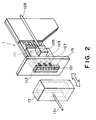
- Figure 2 illustrates a recording head and a cap therefor in the apparatus of Figure 1.
- FIG 3 is a perspective view of an ink cartridge mounting portion in the apparatus of Figure 1.
- Figure 4 is a sectional view of an ink communicating part of an ink cartridge according to a first embodiment of the present invention.
- Figures 5A and 5B are sectional views illustrating operation of the ink cartridge of the first embodiment.
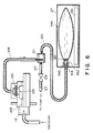
- Figure 6 illustrates operation of the air introduction prior to the recovery operation of the ink supply system in the ink cartridge of the first embodiment.
- Figure 7 is a sectional view illustrating the recovery operation for the ink supply system in the apparatus of the first embodiment.
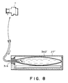
- Figure 8 is a sectional view illustrating the operation when the recording head is dismounted in a conventional apparatus.
- Figure 9 is a sectional view illustrating operation of the air introduction in the conventional ink supply system.
- Figure 10 illustrates manufacturing of the ink cartridge in accordance with a first embodiment of the present invention.
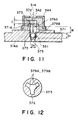
- Figure 11 is a sectional view of an ink communicating position of an ink cartridge according to a second embodiment of the present invention.
- Figure 12 is a sectional view illustrating the configuration of a projection in the cartridge of Figure 11.
- Figure 13 illustrates the manufacturing step of the ink cartridge according to a second embodiment of the present invention.
- Figure 14 is a sectional view of an ink communicating portion of an ink cartridge according to a third embodiment of the present invention.
- FIG 1 there is shown an ink jet recording apparatus according to an embodiment of the present invention.
- a cover has been removed.
- Figure 2 shows a recording head and a cap member of this apparatus.
- the recording head 1 is in the form of a chip and is mountable onto a carriage 2 which is reciprocable.
- the carriage 2 is provided with a supporting member for detachably mounting the recording head 1 thereon and a covering member (chain lines) for protecting a substrate which constitutes a part of the recording head 1 and which has driving circuit or the like printed thereon.
- the recording head 1 is provided with 64 ejection outlets 101 at its front side, although only three ejection outlets are shown in Figure 2.
- Each of the ejection outlets 101 is connected with an ink passage 103 communicating therewith. Behind the ink passage 103, there is a common ink chamber 105 for supplying the ink to the liquid passages 103.
- Each of the ink passages is provided with an electrothermal transducer element 107 for generating thermal energy to create film boiling to eject droplets of the ink through the ejection outlet and is also provided with electrode wiring for supplying electric power to the electrothermal transducer element 107.
- the ink is supplied through a supply tube 109.
- the electrothermal transducer elements 107 and the electrode wiring are formed on a silicone or the like substrate 111 through film formation process.
- the ejection outlets 101, the ink passages 103 and a common liquid chamber 105 are formed. Behind them on the recording head 1, the driving circuits are also printed on the substrate to drive the electrothermal transducer elements in accordance with the recording signal.
- the connector base plate 12 On the carriage 2, there is a connector base plate 12 connected with a connector 9, behind the recording head 1.
- the connector base plate 12 has connectors 9 for electric connection with the recording head 1 and connectors for connection with a flexible cable connected with a control circuit of the main assembly of the recording apparatus.
- the connector base plate 12 is provided with capacitors and resistors, which are effective to compensate voltage drop of the voltage source through the flexible cable and prevent introduction of noise.
- the connector base plate 12 is supported on a sliding member which slides in accordance with opening and closing of the cover member to connect the connector 9 with the contacts of the recording head 1.
- An engaging portion 2a of the carriage 2 is slidably and rotatably engage with a guide shaft 3.
- the guide shaft 3 is extended in a direction perpendicular to the direction of recording material feeding over a range larger than the width of the recording material such as recording sheet.
- the carriage 2 is engaged with a part of an unshown belt stretched in parallel with the guiding shaft 3.
- the belt is driven by a carriage motor not shown to move the carriage 2 along the guide shaft 3, that is, in the scanning direction.
- the carriage 2 and the recording head 1 are rotatable about the guiding shaft 3 by its weight to urge a sheet confining plate 8 through a sliding member of the carriage 2. By doing so, a predetermined interval is assured between the recording sheet and the recording head 1 in accordance with the thickness of the recording sheet.
- the recording sheet 6 is fed from an unshown sheet feeding cassette or is manually fed and is supplied to the main assembly of the recording apparatus through a sheet inlet provided by a top paper guide 7a and a bottom paper guide 7b.
- the top paper guide 7a is connected with the sheet confining plate 8 having a curvature.
- the sheet confining plate 8 is urged to the sheet feeding roller 5, and the friction between the recording sheet with the recording sheet by the urging force is made smaller by selection of the material than the friction force between the sheet feeding roller and the recording sheet.
- the bottom paper guide 7b extends to the position where the sheet feeding roller 5 is disposed in parallel with the sheet confining plate 8.
- the recording sheet 6 thus supplied is fed one by one line upwardly by the rotation of the sheet feeding roller.
- the recording sheet slides on a platen 7 in the form of a plate while keeping a predetermined space from the recording head 1 by the sheet confining plate and the platen 7.
- the recording head 1 ejects the droplets of the ink for the recording region of the recording sheet to effect one line recording, while it is scanningly moved.
- the recording sheet is fed by one line, and by repeating these operations, and the character and/or images are recorded on the sheet sequentially.
- the recording sheet 6 now having the characters and/or the images is discharged onto a sheet discharging tray by discharging rollers 4 and spurs 40a and 40b disposed above the recording sheet passage.
- spurs 40a and 40b Five pairs of spurs 40a and 40b are provided corresponding to the discharging rollers 4 and is provided with spur cleaners between them. Member for supporting the spurs and spur cleaners are omitted in Figure 1.
- the spurs 40a urge the recording sheet to the discharging rollers, and the spurs 40b limit the conveying passage of the recording sheet.
- the sheet discharging roller 4 is rotated to provide a peripheral speed which is larger than that of the sheet feeding roller 5, by which the recording sheet 6 is pulled upwardly in the region constituting the recording region so as to avoid the recording sheet 6 rising from the platen 7.
- a blade 26 for removing by wiping action ink droplets (mist) dust or the like on the ejection side surface where the ejection outlets are disposed
- absorbing material 25 for removing mainly by absorption ink droplets or the like on
- the engagement is established between a hole formed in a capping arm 17 mounted on a side of the supporting member for the gap 13 and a projection on the carriage 2 so as to prevent rearward rotation of the recording head 1, thus assuring the capping of the cap 13 to the ejection side surface.
- the cap 13 is made of elastic member such as rubber, and using the elasticity thereof, the air is urged into the recording head through the ejection outlets, when it is engaged with the recording head 1.
- the rotational driving force of the feed motor 21 is used rotate the sheet feeding roller 5 and the sheet discharging roller 4 and to operate the ejection recovery mechanism, that is, to move the cap 13, the blade 26 and the absorbing material 25 toward and away from the recording head and to carry out the sucking operation with the pump 24. More particularly, the rotational driving force of the feed motor mounted on a part of the main assembly frame is transmitted to a transmission gear train 19.
- the gear grain 19 is effective to select proper gears for movement of the carriage 2, the scanning movement of the recording head 1, movement of the recording head 1 to the home position or to the ejection recovery position and for stoppage at this position, by the selection gears (not shown) in response to these operations.
- the rotation of the gears in the gear train 19 is transmitted through an intermediate gear 20 to the sheet feeding roller 5 and the sheet discharging roller 4, and to an integral cap 13 or the like through a cam 16, and is to the pump 24 through a pump gear 22 and a pump cam 23.
- a hollow needle 314 pierces a plug of an ink cartridge 27 mounted on the main assembly of the recording apparatus, and a flexible tube capable of following movement of the carriage 2 is used.
- the cartridge 27 is at a vertical level lower than the ejection outlets of the recording head.
- the position of the carriage 2 is detected by counting number of steps of the carriage motor on the basis of a reference position where the home position sensor 11 of the carriage 2 corresponds to a home position detecting flag disposed adjacent an end of the moving region of the carriage 2.
- Figure 3 illustrates the interconnection between the ink cartridge 27 and the main assembly.
- Designated by reference numerals 271 and 340 are cartridge casing and an ink bladder for accommodating the ink to be supplied, which is accommodated in turn in the casing 271.
- the bladder has a rubber plug 342.
- the needle 314 is inserted into the plug 342, and further insertion permits communication with the ink.
- An absorbing material 344 functions to accommodate residual ink discharged by the operation of the ejection recovery mechanism through a residual ink pipe 318 and is connected with an ink absorbing material disposed below the ink bladder.
- a wiring pattern 346 is provided on the top surface of the ink cartridge 27, and the controller of the main assembly is able to detect presence or absence of the ink cartridge in accordance with connection or disconnection between contact 306A and 306B through the pattern 346.
- the pattern may be changed in accordance with the color or density of the ink in the resistance of the wiring pattern, and then, the controller of the main assembly is able to aware of the information.
- a click 320 functions as a fastener for the ink cartridge 27, and is provided one at each side of the cartridge receptor.
- the click 320 flexes by its elasticity upon engagement with a side surface of the cartridge 27 when it is inserted or removed, so that the insertion or removal action of the cartridge 27 is permitted, while holding the cartridge 27 at a proper position by restoring its original configuration when it is received by a recess 332 of the cartridge 27.
- Figure 4 shows an example of the ink communicating portion of the ink cartridge.
- a passage forming member in the ink bladder 340 which is effective to provide the liquid passage 352.
- the passage 352 is in a circular form having a diameter D3 at a portion 353, and a diameter D2 which is smaller than the diameter D3 in the portion 355.
- the large diameter and small diameter portions are connected by a portion 357.
- a ball 361 functions as a valve and is made of polytetrafluoroethylene resin and has a diameter D1 which is smaller than the diameter D3 of the passage portion 353 and which is larger than the diameter D2 of the passage portion 355.
- the plug 342 made of rubber or the like covers a projection 351A from the passage forming member 351 from which the passage portion 353 is formed, and is held on the ink bladder 340 by a confining member 344.
- the ball 361 moves from the position indicated by the chain linein the feeding direction by the force resulting from the ink supply from the ink bladder, for example, the flow of the ink. It abuts a tip end of the needle 314, as indicated by the solid lines, and therefore, the tip end is tapered as indicated by a reference 314A, the flow of the ink is not obstructed, and is supplied to the ink supply system as indicated by an arrow.
- the position of the tip end 314A of the needle 314 is so determined that it pushes the ball 361 but does not close the passage. This is accomplished by determining the dimension of the needle and the mounting position thereof or the like so that the positional relations as shown in Figure 5 is established at the click position.
- FIG. 6 and 7 there is illustrated an ink supply system in the air charging and sucking operation for the purpose of ejection recovery.
- An ink absorbing material 281 is disposed at the bottom of the cartridge 27.
- a subordinate container 121 is provided to trap the air in the ink supply system and to prevent transmission of the pressure change resulting from the carriage movement to the recording head.
- a tube 123 functions to connect the ink cartridge 27 and the subordinate container 121.
- a filter 125 functions to remove the dust or fine air bubbles from the ink introduced into the common chamber 105 from the subordinate tank 121.
- a tube 127 provides communication between the subordinate tank 121 and the pump 24. When the liquid level of the subordinate tank is to be adjusted, the liquid is sucked through the tube 127.
- the tube 127 is provided with a valve 129.
- the valve 129 takes its closing position, the air is charged into the ejection outlets by one or repeated abutment action of the elastic cap 13 to the recording head 1 with or without the aid of pressing pump.
- the air reaches to the common chamber 105, but in the ink cartridge 27, the ball 361 closes the passage 352, and therefore, the air is not introduced into the ink bladder 341. Therefore, the cartridge failure as a result of air introduction does not result.
- the valve 129 is then closed, and the pump 24 is operated to effect the sucking action.
- the ball 361 closes the passage, and therefore, the ink is permitting to flow out to the supply system.
- the charged air and the ink are sucked into the cap 23 or to the pump 24, so that the ink is refreshed.
- the sucking operation is also effected to the subordinate container 121.
- the air is not introduced improperly in the bladder, and therefore, the air bubble is prevented from entering the ink, and the quantity of the ink consumed for the sucking operation is small.
- the preferable position is such that the force provided by the ink is larger, that is, the static head difference is larger. From this standpoint, the position in the ink cartridge 27 is preferable.
- the non-existence of the air at the position is preferable, and therefore, the position is further preferably suck that the air is not introduced along the pipe wall of the supply system or by the charging of the air.
- the recording apparatus of this embodiment is in the form of a serial scan type printer, and therefore a part of the ink supply system is made of flexible tube to follow the movement of the recording head.
- the structure described above is hardly influenced by the motion of the ink resulting from the scanning movement, and therefore, the erroneous operation of the valve hardly occurs.
- FIG 10 illustrates an example of manufacturing of the cartridge 27.
- the ink bladder 341 is filled with the ink.
- the ball 361 is set in the passage 352, and thereafter the rubber plug 342 is set at step STP5.
- the ink bladder is accommodated in the cartridge casing, and the cover is mounted, thus completing the assembling (STP).
- a hollow needle is pierced to effect sucking operation to remove the air bubbles from the bladder.
- the next step is carried out.
- the confining member 344 is integral with the casing and the cover.
- the sucking operation at step STP9 the slight vacuum is produced in the ink bladder, and therefore, the ball 361 is closely contacted to the passage wall 355, and therefore, the ink leakage is effectively prevented when it is carried around.
- FIG 11 shows an ink communicating portion of the ink cartridge 27 according to another embodiment of the present invention.
- the same reference numerals as in Figure 4 are assigned to the corresponding elements.
- designated by a reference numeral 371 is a passage forming member for forming a liquid passage 372.
- the liquid passage 372 includes a passage portion 373 having a circular cross-section and a passage portion 375 having a diameter smaller than that of the passage portion 373. It also includes a portion communicating these passage portions.
- These structures are similar as in the foregoing embodiment. In this embodiment, however, there are projections 379A and 379B projected inwardly at the passage portion 373. During the manufacturing step, the ball 361 is temporarily held between the projections.
- the inside diameters D4 of the projections 379A and 379B are smaller than the diameter D1 of the ball 361.
- the projections 379A and 379B are preferably of plural projections along the passage 373 wall as shown in Figure 12 rather than in the form of a continuous annular projections, in consideration of the temporary supporting of the ball 361, filling of the bladder with the ink, setting of the ball 361 to the shown position and the ink supply during recording operation. Then, the ball is easily set beyond the projections, and the ink passage is provided for filling the bladder with the ink between the divided projections.
- the intervals between the projections 379A and 379B are so selected that it is larger than the diameter D1 of the ball 361.
- the needle 314 pushes the ball 361 beyond the projection 379B.
- the tip end 314A of the needle is preferably reaches a position more than D1/2 away from the projection 379B toward the ink bladder side.
- the improper air introduction by the reverse flow of the ink can be similarly prevented, and therefore proper ink supply can be maintained.
- the tip end position of the needle 314 is so determined that it does not urge the ball 361 to the passage portion 375.
- the end position is, however, is above the projection 379B so as to prevent the contact between the ball 361 and the tip end, and therefore, the damage of the ball 361 or the needle 314 by the contact can be avoided.
- the distance t between the inside bottom of the plug 342 and the top surface of the projection 371A of the passage forming member 371 covered by the plug 342 is not particularly considered, because the ball 361 does not fall in this embodiment.
- Figure 13 illustrates the manufacturing step , of the cartridge 27.
- the ball 361 is pressed to between the upper and lower projections 379A and 379B of the passage forming member 371 of the ink bladder 340.
- the rubber plug 342 is set. Thereafter, the ink bladder 340 is accommodated in the cartridge casing, and the cover is mounted, thus completing the assembling of the cartridge 27 (step 15).
- step STP17 the proper hollow needle N is pierced into the plug 342 to supply the ink and discharge the air. At this time, the flow of the ink and the air are through the clearance between the segments of projections 379A and 379B.
- a proper pushing rod B (the needle N may be usable for this purpose) is used to push the ball 361 to below the projection 379B, at step 19. Then, the package is processed to the next inspection and package steps.
- the upper projections 379A is not always necessary from the standpoint of the function of the ink cartridge.
- the ink cartridge may be put on sale with the ball 361 placed between the projections 379A and 379B. In this case, by mounting the cartridge in the apparatus, the ink supply needle urges the ball 361.
- Figure 14 illustrates an ink cartridge according to a third embodiment which is a modification of the first embodiment.
- This embodiment is similar to Figure 4 embodiment with the exception that the passage forming member 381 having a passage portion 385 with an inside diameter which is smaller than the ball 361 is mounted to the outlet side of the passage forming member 351.
- the end of the needle 341 is placed outside the passage portion 185, so that the ink supply is not obstructed.
- the ink reverse preventing effect is the same as in the foregoing embodiments.
- the ink leakage from the ink cartridge 27 after it is removed after use-up of the cartridge can be accomplished. If the plug 142 is deteriorated in its material with time, the pierce by the needle 114 is not completely closed when the cartridge is removed from the main assembly of the recording apparatus. If this is the case, the remaining ink may leak out. According to this embodiment, however, the leaking motion of the ink is effective to displace the ball 161 toward the outlet so as to close the passage 195. Therefore, the leakage of the ink can be prevented.
- the passage of this embodiment can be formed through the similar steps as in Figure 10 but with an additional step between the step STP1 and the step STP5 a step of mounting the member 181 by bonding or the like.
- the clearance t is not particularly considered. This is similar to the case of the second embodiment.
- the present invention is particularly suitably usable in an ink jet recording head and recording apparatus wherein thermal energy by an electrothermal transducer, laser beam or the like is used to cause a change of state of the ink to eject or discharge the ink. This is because the high density of the picture elements and the high resolution of the recording are possible.
- the typical structure and the operational principle are preferably the ones disclosed in U.S. Patent Nos. 4,721,129 and 4,740,796.
- the principle and structure are applicable to a so-called on-demand type recording system and a continuous type recording system. Particularly, however, it is suitable for the on-demand type because the principle is such that at least one driving signal is applied to an electrothermal transducer disposed on a liquid (ink) retaining sheet or liquid passage, the driving signal being enough to provide such a quick temperature rise beyond a departure from nucleation boiling point, by which the thermal energy is provided by the electrothermal transducer to produce film boiling on the heating portion of the recording head, whereby a bubble can be formed in the liquid (ink) corresponding to each of the driving signals.
- the liquid (ink) is ejected through an ejection outlet to produce at least one droplet.
- the driving signal preferably in the form of a pulse, because the development and contraction of the bubble can be effected instantaneously, and therefore, the liquid (ink) is ejected with quick response.
- the driving signal in the form of the pulse is preferably such as disclosed in U.S. Patents Nos. 4,463,359 and 4,345,262.
- the temperature increasing rate of the heating surface is preferably such as disclosed in U.S. Patent No. 4,313,124.
- the structure of the recording head may be as shown in U.S. Patent Nos. 4,558,333 and 4,459,600 wherein the heating portion is disposed at a bent portion, as well as the structure of the combination of the ejection outlet, liquid passage and the electrothermal transducer as disclosed in the above-mentioned patents.
- the present invention is applicable to the structure disclosed in Japanese Laid-Open Patent Application No. 123670/1984 wherein a common slit is used as the ejection outlet for plural electrothermal transducers, and to the structure disclosed in Japanese Laid-Open Patent Application No. 138461/1984 wherein an opening for absorbing pressure wave of the thermal energy is formed corresponding to the ejecting portion. This is because the present invention is effective to perform the recording operation with certainty and at high efficiency irrespective of the type of the recording head.
- the present invention is effectively applicable to a so-called full-line type recording head having a length corresponding to the maximum recording width.
- a recording head may comprise a single recording head and plural recording head combined to cover the maximum width.
- the present invention is applicable to a serial type recording head wherein the recording head is fixed on the main assembly, to a replaceable chip type recording head which is connected electrically with the main apparatus and can be supplied with the ink when it is mounted in the main assembly, or to a cartridge type recording head having an integral ink container.
- the provisions of the recovery means and/or the auxiliary means for the preliminary operation are preferable, because they can further stabilize the effects of the present invention.
- preliminary heating means which may be the electrothermal transducer, an additional heating element or a combination thereof.
- means for effecting preliminary ejection (not for the recording operation) can stabilize the recording operation.
- the recording head mountable may be a single corresponding to a single color ink, or may be plural corresponding to the plurality of ink materials having different recording color or density.
- the present invention is effectively applicable to an apparatus having at least one of a monochromatic mode mainly with black, a multi-color mode with different color ink materials and/or a full-color mode using the mixture of the colors, which may be an integrally formed recording unit or a combination of plural recording heads.
- the ink has been liquid. It may be, however, an ink material which is solidified below the room temperature but liquefied at the room temperature. Since the ink is controlled within the temperature not lower than 30 °C and not higher than 70 °C to stabilize the viscosity of the ink to provide the stabilized ejection in usual recording apparatus of this type, the ink may be such that it is liquid within the temperature range when the recording signal is the present invention is applicable to other types of ink. In one of them, the temperature rise due to the thermal energy is positively prevented by consuming it for the state change of the ink from the solid state to the liquid state. Another ink material is solidified when it is left, to prevent the evaporation of the ink.
- the ink is liquefied, and the liquefied ink may be ejected.
- Another ink material may start to be solidified at the time when it reaches the recording material.
- the present invention is also applicable to such an ink material as is liquefied by the application of the thermal energy.
- Such an ink material may be retained as a liquid or solid material in through holes or recesses formed in a porous sheet as disclosed in Japanese Laid-Open Patent Application No. 56847/1979 and Japanese Laid-Open Patent Application No. 71260/1985. The sheet is faced to the electrothermal transducers. The most effective one for the ink materials described above is the film boiling system.
- the ink jet recording apparatus may be used as an output terminal of an information processing apparatus such as computer or the like, as a copying apparatus combined with an image reader or the like, or as a facsimile machine having information sending and receiving functions.
- the reverse flow of the ink to the ink container is effectively prevented. Therefore, the introduction of the air into the ink supply system during the ejection recovery operation including the air charging through the ejection outlets and when the recording head is dismounted. Thus, the consumption of the ink in the recovery operation or the ink refilling operation can be reduced.
Abstract
An ink container cartridge (27) includes an ink containing portion; a plug (342) for being pierced by a hollow needle (314); a device for preventing reverse flow of the ink to the containing portion, the preventing device comprising a valve (361), a first liquid passage in which the valve is movable and a second passage disposed closer to the ink containing portion than the first passage, and the valve (361) is capable of closing the second passage.
Description
- The present invention relates to an ink container cartridge containing ink to be supplied to the recording head and a manufacturing method therefor.
- Various types of recording apparatus for effecting recording on a sheet of paper or OHP sheet or the like are used, and they use various types of recording head. The types of the recording heads include a wire dot type, a heat sensitive type, a heat transfer type or an ink jet type. Among them, the ink jet type is recently particularly noted because of its low running cost and lost noise, since the ink is directly ejected to the recording sheet.
- The ink jet recording apparatus of the ink jet type uses a recording head cartridge which is detachably mountable to the recording apparatus, the recording head cartridge comprising the recording head and an integral ink container. In order to make the ink replenishing operation resulting from the use-up of the ink, the ink container (ink supply source) is made detachably mountable to the main assembly of the recording apparatus, so as to permit the operator replaces the used-up ink container with a flesh ink container. Such a type of ink container is called ink cartridge.
- The ink container cartridge may include an ink bladder coated with aluminum laminate or the like in consideration of prevention from the ink deterioration by being exposed to light, the sealing of the ink and against the air, and the pressure balance in the ink supply system. In addition, in consideration of the easy handing of the cartridge, the ink bladder may be accommodated in a casing. The ink bladder is provided with a plug made of rubber or the like. The ink supply is established by piercing the plug with a hollow needle of an ink supply system of the ink jet recording apparatus main assembly. The meniscus retaining force at the ink ejection outlets and the static head difference between the recording head and the ink container cartridge are balanced, and the ink is supplied into the recording head by the capillary action of the ink supply system such as tube.
- However, with the conventional structure, the ink flows in the opposite direction in the ink container with the result of trouble in the operation. When the recording head is removed from the main assembly for the purpose of maintenance operation, the connecting portion between the ink supply system and the recording head is opened to the air, and therefore, the balance between the meniscus of the recording head and the static head difference is disturbed with the result of the reverse flow of the ink to the ink container, and a great quantity of the air may be introduced in the ink supply system, that is, the tube, for example. This will be described in detail in comparison with the embodiment of the present invention.
- During the ejection recovery process of the recording head, the air is positively introduced through the ejection outlets, and then, the air is sucked out to remove at once the various foreign matters such as air bubbles, dust and viscosity increased ink stagnating in the neighborhood of a common ink chamber, together with the introduced air. In such a case, the balance between the meniscus and the head difference is disturbed, with the result that the ink in the ink supply tube returns into the ink container, and the ink supply tube is filled with the air.
- If the ink in the ink supply system flows back into the ink container, and the air is introduced, the quantity of ink is significantly large in order to recover the ejection operation by the sucking of the ink to restabilize the ink supply system, so that the great amount of ink is consumed without recording. In the case of the recording head cartridge having the integral recording head and the ink container, is free of such a problem. However, the pressure in the ink container is vacuum, and therefore, there is a liability of introducing the air into the ink container. If the air is introduced into the air, no sufficient ink supply can not be achieved with the result of interruption of the printing operation. If the ambient condition change occurs, particularly from the temperature change from low temperature to the high temperature causes expansion of the air, with the result of pressurized ink container. If this occurs, the ink may leak out.
- In order to solve such a problem, U.S. Patent No. 4,931,812, proposes that an "L" shaped ink passage connecting the recording head and the ink container is utilized, and a ball is placed therein to prevent introduction of the air. However, the structure is not usable with the ink container cartridge because it is directed to the recording head cartridge.
- Accordingly, it is an object of the present invention to provide an ink container cartridge wherein the ink supply failure due to the air introduction is effectively prevented.
- It is another object of the present invention to provide an ink container cartridge wherein the back-flow of the ink is effectively prevented.
- According to an aspect of the present invention, there is provided an ink container cartridge, comprising: an ink containing portion; a plug for being pierced by a hollow needle; means for preventing reverse flow of the ink to said containing portion, said preventing means comprising a valve, a first liquid passage in which said valve is movable and a second passage disposed closer to said ink containing portion than said first passage, and said valve is capable of closing the second passage.
- According to another aspect of the present invention, there is provided a method of manufacturing an ink cartridge, comprising: preparing an ink container having an ink containing portion, a liquid passage communicating with the ink containing portion and a plug for plugging the liquid passage; filling the containing portion with ink; mounting a valve into the liquid passage; mounting the plug; effecting sucking through the plug to discharge air from said containing portion.
- According to a further aspect of the present invention, said valve is set between the projections before said plugging step, and the valve is urged inwardly beyond the first projection.
- According to a yet further aspect of the present invention, there is provided an ink jet recording apparatus, comprising: an ink container cartridge including an ink containing portion; a plug for being pierced by a hollow needle; means for preventing reverse flow of the ink to said containing portion, said preventing means comprising a valve, a first liquid passage in which said valve is movable and a second passage disposed closer to said ink containing portion than said first passage, and said valve is capable of closing the second passage; a recording head having a portion detachably mounting said ink container cartridge; means for receiving the recording head; and recovery means for recovering operation of said recording head.
- The recovery means may introduced the air through the ink ejection outlets of the recording head prior to the recovering operation.
- According to the present invention, the reverse flow of the ink to the ink container is effectively prevented, and therefore, the introduction of the air into the ink supply system can be prevented when the recording head is dismounted or in the recovery operation in which the air is introduced through the ejection outlets. Therefore, the quantity of the ink consumed for the ejection recovery operation for refilling the ink in the ink supply system or the recording head, can be reduced.
- These and other objects, features and advantages of the present invention will become more apparent upon a consideration of the following description of the preferred embodiments of the present invention taken in conjunction with the accompanying drawings.
- Figure 1 is a perspective view of an ink jet recording apparatus to which the present invention is applicable.
- Figure 2 illustrates a recording head and a cap therefor in the apparatus of Figure 1.
- Figure 3 is a perspective view of an ink cartridge mounting portion in the apparatus of Figure 1.
- Figure 4 is a sectional view of an ink communicating part of an ink cartridge according to a first embodiment of the present invention.
- Figures 5A and 5B are sectional views illustrating operation of the ink cartridge of the first embodiment.
- Figure 6 illustrates operation of the air introduction prior to the recovery operation of the ink supply system in the ink cartridge of the first embodiment.
- Figure 7 is a sectional view illustrating the recovery operation for the ink supply system in the apparatus of the first embodiment.
- Figure 8 is a sectional view illustrating the operation when the recording head is dismounted in a conventional apparatus.
- Figure 9 is a sectional view illustrating operation of the air introduction in the conventional ink supply system.
- Figure 10 illustrates manufacturing of the ink cartridge in accordance with a first embodiment of the present invention.
- Figure 11 is a sectional view of an ink communicating position of an ink cartridge according to a second embodiment of the present invention.
- Figure 12 is a sectional view illustrating the configuration of a projection in the cartridge of Figure 11.
- Figure 13 illustrates the manufacturing step of the ink cartridge according to a second embodiment of the present invention.
- Figure 14 is a sectional view of an ink communicating portion of an ink cartridge according to a third embodiment of the present invention.
- Referring to Figure 1, there is shown an ink jet recording apparatus according to an embodiment of the present invention. In this Figure, a cover has been removed. Figure 2 shows a recording head and a cap member of this apparatus.
- The
recording head 1 is in the form of a chip and is mountable onto acarriage 2 which is reciprocable. Thecarriage 2 is provided with a supporting member for detachably mounting therecording head 1 thereon and a covering member (chain lines) for protecting a substrate which constitutes a part of therecording head 1 and which has driving circuit or the like printed thereon. - As shown in Figure 2, the
recording head 1 is provided with 64ejection outlets 101 at its front side, although only three ejection outlets are shown in Figure 2. Each of theejection outlets 101 is connected with anink passage 103 communicating therewith. Behind theink passage 103, there is acommon ink chamber 105 for supplying the ink to theliquid passages 103. Each of the ink passages is provided with anelectrothermal transducer element 107 for generating thermal energy to create film boiling to eject droplets of the ink through the ejection outlet and is also provided with electrode wiring for supplying electric power to theelectrothermal transducer element 107. To thecommon chamber 103, the ink is supplied through asupply tube 109. - The
electrothermal transducer elements 107 and the electrode wiring are formed on a silicone or the like substrate 111 through film formation process. By laminatingpartition forming members 113 of resin or glass material and atop plate 115 or the like, theejection outlets 101, theink passages 103 and a commonliquid chamber 105 are formed. Behind them on therecording head 1, the driving circuits are also printed on the substrate to drive the electrothermal transducer elements in accordance with the recording signal. - On the
carriage 2, there is aconnector base plate 12 connected with aconnector 9, behind therecording head 1. Theconnector base plate 12 hasconnectors 9 for electric connection with therecording head 1 and connectors for connection with a flexible cable connected with a control circuit of the main assembly of the recording apparatus. Theconnector base plate 12 is provided with capacitors and resistors, which are effective to compensate voltage drop of the voltage source through the flexible cable and prevent introduction of noise. Theconnector base plate 12 is supported on a sliding member which slides in accordance with opening and closing of the cover member to connect theconnector 9 with the contacts of therecording head 1. - An
engaging portion 2a of thecarriage 2 is slidably and rotatably engage with aguide shaft 3. Theguide shaft 3 is extended in a direction perpendicular to the direction of recording material feeding over a range larger than the width of the recording material such as recording sheet. Thecarriage 2 is engaged with a part of an unshown belt stretched in parallel with the guidingshaft 3. The belt is driven by a carriage motor not shown to move thecarriage 2 along theguide shaft 3, that is, in the scanning direction. Thecarriage 2 and therecording head 1 are rotatable about the guidingshaft 3 by its weight to urge a sheet confining plate 8 through a sliding member of thecarriage 2. By doing so, a predetermined interval is assured between the recording sheet and therecording head 1 in accordance with the thickness of the recording sheet. - The
recording sheet 6 is fed from an unshown sheet feeding cassette or is manually fed and is supplied to the main assembly of the recording apparatus through a sheet inlet provided by atop paper guide 7a and abottom paper guide 7b. Thetop paper guide 7a is connected with the sheet confining plate 8 having a curvature. The sheet confining plate 8 is urged to thesheet feeding roller 5, and the friction between the recording sheet with the recording sheet by the urging force is made smaller by selection of the material than the friction force between the sheet feeding roller and the recording sheet. Thebottom paper guide 7b extends to the position where thesheet feeding roller 5 is disposed in parallel with the sheet confining plate 8. - The
recording sheet 6 thus supplied is fed one by one line upwardly by the rotation of the sheet feeding roller. The recording sheet slides on aplaten 7 in the form of a plate while keeping a predetermined space from therecording head 1 by the sheet confining plate and theplaten 7. Therecording head 1 ejects the droplets of the ink for the recording region of the recording sheet to effect one line recording, while it is scanningly moved. Then, the recording sheet is fed by one line, and by repeating these operations, and the character and/or images are recorded on the sheet sequentially. Therecording sheet 6 now having the characters and/or the images is discharged onto a sheet discharging tray by discharging rollers 4 and spurs 40a and 40b disposed above the recording sheet passage. Five pairs of spurs 40a and 40b are provided corresponding to the discharging rollers 4 and is provided with spur cleaners between them. Member for supporting the spurs and spur cleaners are omitted in Figure 1. The spurs 40a urge the recording sheet to the discharging rollers, and the spurs 40b limit the conveying passage of the recording sheet. The sheet discharging roller 4 is rotated to provide a peripheral speed which is larger than that of thesheet feeding roller 5, by which therecording sheet 6 is pulled upwardly in the region constituting the recording region so as to avoid therecording sheet 6 rising from theplaten 7. - Adjacent a home position of the
recording head 1 continuing from the scanning region, there is a set of ejection recovery mechanisms, such as ablade 26 for removing by wiping action ink droplets (mist) dust or the like on the ejection side surface where the ejection outlets are disposed, absorbingmaterial 25 for removing mainly by absorption ink droplets or the like on the ejection side surface, and acap 13 for hermetically capping the ejection side surface for permitting idle ejections and ink sucking. They are integrally supported on a supportingmember 14 for movement toward an away from the moving region of therecording head 1. They are operated proper timings. The ink is sucked from the capped space through atube 131 and by apump 24 connected with thetube 131. Upon the capping, the engagement is established between a hole formed in acapping arm 17 mounted on a side of the supporting member for thegap 13 and a projection on thecarriage 2 so as to prevent rearward rotation of therecording head 1, thus assuring the capping of thecap 13 to the ejection side surface. Thecap 13 is made of elastic member such as rubber, and using the elasticity thereof, the air is urged into the recording head through the ejection outlets, when it is engaged with therecording head 1. - The rotational driving force of the
feed motor 21 is used rotate thesheet feeding roller 5 and the sheet discharging roller 4 and to operate the ejection recovery mechanism, that is, to move thecap 13, theblade 26 and the absorbingmaterial 25 toward and away from the recording head and to carry out the sucking operation with thepump 24. More particularly, the rotational driving force of the feed motor mounted on a part of the main assembly frame is transmitted to atransmission gear train 19. Thegear grain 19 is effective to select proper gears for movement of thecarriage 2, the scanning movement of therecording head 1, movement of therecording head 1 to the home position or to the ejection recovery position and for stoppage at this position, by the selection gears (not shown) in response to these operations. The rotation of the gears in thegear train 19 is transmitted through anintermediate gear 20 to thesheet feeding roller 5 and the sheet discharging roller 4, and to anintegral cap 13 or the like through acam 16, and is to thepump 24 through apump gear 22 and apump cam 23. - As regards the ink supply to the
recording head 1, ahollow needle 314 pierces a plug of anink cartridge 27 mounted on the main assembly of the recording apparatus, and a flexible tube capable of following movement of thecarriage 2 is used. As will be understood from Figure 1 and other drawings, thecartridge 27 is at a vertical level lower than the ejection outlets of the recording head. The position of thecarriage 2 is detected by counting number of steps of the carriage motor on the basis of a reference position where the home position sensor 11 of thecarriage 2 corresponds to a home position detecting flag disposed adjacent an end of the moving region of thecarriage 2. - Figure 3 illustrates the interconnection between the
ink cartridge 27 and the main assembly. Designated byreference numerals casing 271. The bladder has arubber plug 342. Theneedle 314 is inserted into theplug 342, and further insertion permits communication with the ink. An absorbingmaterial 344 functions to accommodate residual ink discharged by the operation of the ejection recovery mechanism through aresidual ink pipe 318 and is connected with an ink absorbing material disposed below the ink bladder. - A
wiring pattern 346 is provided on the top surface of theink cartridge 27, and the controller of the main assembly is able to detect presence or absence of the ink cartridge in accordance with connection or disconnection betweencontact pattern 346. The pattern may be changed in accordance with the color or density of the ink in the resistance of the wiring pattern, and then, the controller of the main assembly is able to aware of the information. - A
click 320 functions as a fastener for theink cartridge 27, and is provided one at each side of the cartridge receptor. Theclick 320 flexes by its elasticity upon engagement with a side surface of thecartridge 27 when it is inserted or removed, so that the insertion or removal action of thecartridge 27 is permitted, while holding thecartridge 27 at a proper position by restoring its original configuration when it is received by arecess 332 of thecartridge 27. - Figure 4 shows an example of the ink communicating portion of the ink cartridge. Designated by a
reference 351 is a passage forming member in theink bladder 340, which is effective to provide theliquid passage 352. Thepassage 352 is in a circular form having a diameter D3 at aportion 353, and a diameter D2 which is smaller than the diameter D3 in theportion 355. The large diameter and small diameter portions are connected by aportion 357. Aball 361 functions as a valve and is made of polytetrafluoroethylene resin and has a diameter D1 which is smaller than the diameter D3 of thepassage portion 353 and which is larger than the diameter D2 of thepassage portion 355. Theplug 342 made of rubber or the like covers aprojection 351A from thepassage forming member 351 from which thepassage portion 353 is formed, and is held on theink bladder 340 by a confiningmember 344. - During the ink supply in the normal recording and in the ejection recovery operation, as shown in Figure 5A, the
ball 361 moves from the position indicated by the chain linein the feeding direction by the force resulting from the ink supply from the ink bladder, for example, the flow of the ink. It abuts a tip end of theneedle 314, as indicated by the solid lines, and therefore, the tip end is tapered as indicated by areference 314A, the flow of the ink is not obstructed, and is supplied to the ink supply system as indicated by an arrow. - When, on the other hand, the
recording head 1 is removed from the main assembly or when the air is charged with the aid of thecap 13, the ink once flows back to the bladder, but as shown in Figure 5B, theball 361 moves in the opposite direction by the force resulting from the reverse flow from the position indicated by the chain line, until it closes thepassage portion 355 as shown by the solid line. It is retained thereby the force from the ink, so that the backward flow of the ink toward the ink bladder 341 is stopped. - The position of the
tip end 314A of theneedle 314 is so determined that it pushes theball 361 but does not close the passage. This is accomplished by determining the dimension of the needle and the mounting position thereof or the like so that the positional relations as shown in Figure 5 is established at the click position. - The advantageous effects of the present invention will be described with respect to the ejection recovery operation.
- Referring to Figures 6 and 7, there is illustrated an ink supply system in the air charging and sucking operation for the purpose of ejection recovery. An
ink absorbing material 281 is disposed at the bottom of thecartridge 27. Asubordinate container 121 is provided to trap the air in the ink supply system and to prevent transmission of the pressure change resulting from the carriage movement to the recording head. Atube 123 functions to connect theink cartridge 27 and thesubordinate container 121. Afilter 125 functions to remove the dust or fine air bubbles from the ink introduced into thecommon chamber 105 from thesubordinate tank 121. Atube 127 provides communication between thesubordinate tank 121 and thepump 24. When the liquid level of the subordinate tank is to be adjusted, the liquid is sucked through thetube 127. Thetube 127 is provided with avalve 129. - As shown in Figure 6, in the recovery operation, the
valve 129 takes its closing position, the air is charged into the ejection outlets by one or repeated abutment action of theelastic cap 13 to therecording head 1 with or without the aid of pressing pump. The air reaches to thecommon chamber 105, but in theink cartridge 27, theball 361 closes thepassage 352, and therefore, the air is not introduced into the ink bladder 341. Therefore, the cartridge failure as a result of air introduction does not result. - As shown in Figure 7, the
valve 129 is then closed, and thepump 24 is operated to effect the sucking action. At this time, theball 361 closes the passage, and therefore, the ink is permitting to flow out to the supply system. The charged air and the ink are sucked into thecap 23 or to thepump 24, so that the ink is refreshed. At this time, the sucking operation is also effected to thesubordinate container 121. In this embodiment, the air is not introduced improperly in the bladder, and therefore, the air bubble is prevented from entering the ink, and the quantity of the ink consumed for the sucking operation is small. - In the case of the
cartridge 27 without the check valve for preventing the reverse flow of the ink into the ink,bladder 340′ as shown in Figures 8 and 9, when the recording head is dismounted or when the ejection recovery operation charges the air into the recording head, the pressure balance between the ink container and the ink supply is disturbed with the result of improper air introduction, and therefore, larger sucking force is required to suck the ink to the recording head, and the quantity of the ink consumed in the subsequent sucking operation is larger. - It would be considered to dispose the structure for preventing the improper air introduction in a position halfway of the ink supply system. However, in order to smoothly and effectively operate the valve, the preferable position is such that the force provided by the ink is larger, that is, the static head difference is larger. From this standpoint, the position in the
ink cartridge 27 is preferable. In addition, in order to effectively operate the valve, the non-existence of the air at the position is preferable, and therefore, the position is further preferably suck that the air is not introduced along the pipe wall of the supply system or by the charging of the air. The recording apparatus of this embodiment is in the form of a serial scan type printer, and therefore a part of the ink supply system is made of flexible tube to follow the movement of the recording head. The structure described above is hardly influenced by the motion of the ink resulting from the scanning movement, and therefore, the erroneous operation of the valve hardly occurs. - Figure 10 illustrates an example of manufacturing of the
cartridge 27. At step STP1, the ink bladder 341 is filled with the ink. At step STP3, theball 361 is set in thepassage 352, and thereafter therubber plug 342 is set at step STP5. Then, the ink bladder is accommodated in the cartridge casing, and the cover is mounted, thus completing the assembling (STP). At step STP9, a hollow needle is pierced to effect sucking operation to remove the air bubbles from the bladder. Then, the next step (inspection and package) is carried out. In this example, the confiningmember 344 is integral with the casing and the cover. - By the sucking operation at step STP9, the slight vacuum is produced in the ink bladder, and therefore, the
ball 361 is closely contacted to thepassage wall 355, and therefore, the ink leakage is effectively prevented when it is carried around. - Figure 11 shows an ink communicating portion of the
ink cartridge 27 according to another embodiment of the present invention. The same reference numerals as in Figure 4 are assigned to the corresponding elements. In this Figure, designated by areference numeral 371 is a passage forming member for forming aliquid passage 372. Theliquid passage 372 includes apassage portion 373 having a circular cross-section and apassage portion 375 having a diameter smaller than that of thepassage portion 373. It also includes a portion communicating these passage portions. These structures are similar as in the foregoing embodiment. In this embodiment, however, there areprojections passage portion 373. During the manufacturing step, theball 361 is temporarily held between the projections. To accomplish this, the inside diameters D4 of theprojections ball 361. Theprojections passage 373 wall as shown in Figure 12 rather than in the form of a continuous annular projections, in consideration of the temporary supporting of theball 361, filling of the bladder with the ink, setting of theball 361 to the shown position and the ink supply during recording operation. Then, the ball is easily set beyond the projections, and the ink passage is provided for filling the bladder with the ink between the divided projections. The intervals between theprojections ball 361. By mounting the cartridge to the apparatus, theneedle 314 pushes theball 361 beyond theprojection 379B. To accomplish this, thetip end 314A of the needle is preferably reaches a position more than D1/2 away from theprojection 379B toward the ink bladder side. - In this embodiment, the improper air introduction by the reverse flow of the ink can be similarly prevented, and therefore proper ink supply can be maintained. Similarly to the foregoing embodiment, the tip end position of the
needle 314 is so determined that it does not urge theball 361 to thepassage portion 375. The end position is, however, is above theprojection 379B so as to prevent the contact between theball 361 and the tip end, and therefore, the damage of theball 361 or theneedle 314 by the contact can be avoided. The distance t between the inside bottom of theplug 342 and the top surface of theprojection 371A of thepassage forming member 371 covered by theplug 342 is not particularly considered, because theball 361 does not fall in this embodiment. - Figure 13 illustrates the manufacturing step , of the
cartridge 27. At step STP11, theball 361 is pressed to between the upper andlower projections passage forming member 371 of theink bladder 340. At step STP13, therubber plug 342 is set. Thereafter, theink bladder 340 is accommodated in the cartridge casing, and the cover is mounted, thus completing the assembling of the cartridge 27 (step 15). - Then, at step STP17, the proper hollow needle N is pierced into the
plug 342 to supply the ink and discharge the air. At this time, the flow of the ink and the air are through the clearance between the segments ofprojections ball 361 to below theprojection 379B, atstep 19. Then, the package is processed to the next inspection and package steps. Theupper projections 379A is not always necessary from the standpoint of the function of the ink cartridge. However, in order to prevent falling of theball 361 between the step STP11 and the step STP13, and in order to prevent vibration or movement of theball 361 when the ink is injected at step STP11, thus avoiding damage by the contact between the needle N and theball 361, it is preferable to provide theupper projections 379A. - The ink cartridge may be put on sale with the
ball 361 placed between theprojections ball 361. - Figure 14 illustrates an ink cartridge according to a third embodiment which is a modification of the first embodiment. This embodiment is similar to Figure 4 embodiment with the exception that the
passage forming member 381 having apassage portion 385 with an inside diameter which is smaller than theball 361 is mounted to the outlet side of thepassage forming member 351. During the normal ink supply, the end of the needle 341 is placed outside the passage portion 185, so that the ink supply is not obstructed. - The ink reverse preventing effect is the same as in the foregoing embodiments. In this embodiment, the ink leakage from the
ink cartridge 27 after it is removed after use-up of the cartridge can be accomplished. If the plug 142 is deteriorated in its material with time, the pierce by the needle 114 is not completely closed when the cartridge is removed from the main assembly of the recording apparatus. If this is the case, the remaining ink may leak out. According to this embodiment, however, the leaking motion of the ink is effective to displace the ball 161 toward the outlet so as to close the passage 195. Therefore, the leakage of the ink can be prevented. - The passage of this embodiment can be formed through the similar steps as in Figure 10 but with an additional step between the step STP1 and the step STP5 a step of mounting the member 181 by bonding or the like. In this embodiment, the clearance t is not particularly considered. This is similar to the case of the second embodiment.
- The present invention is particularly suitably usable in an ink jet recording head and recording apparatus wherein thermal energy by an electrothermal transducer, laser beam or the like is used to cause a change of state of the ink to eject or discharge the ink. This is because the high density of the picture elements and the high resolution of the recording are possible.
- The typical structure and the operational principle are preferably the ones disclosed in U.S. Patent Nos. 4,721,129 and 4,740,796. The principle and structure are applicable to a so-called on-demand type recording system and a continuous type recording system. Particularly, however, it is suitable for the on-demand type because the principle is such that at least one driving signal is applied to an electrothermal transducer disposed on a liquid (ink) retaining sheet or liquid passage, the driving signal being enough to provide such a quick temperature rise beyond a departure from nucleation boiling point, by which the thermal energy is provided by the electrothermal transducer to produce film boiling on the heating portion of the recording head, whereby a bubble can be formed in the liquid (ink) corresponding to each of the driving signals. By the production, development and contraction of the the bubble, the liquid (ink) is ejected through an ejection outlet to produce at least one droplet. The driving signal preferably in the form of a pulse, because the development and contraction of the bubble can be effected instantaneously, and therefore, the liquid (ink) is ejected with quick response. The driving signal in the form of the pulse is preferably such as disclosed in U.S. Patents Nos. 4,463,359 and 4,345,262. In addition, the temperature increasing rate of the heating surface is preferably such as disclosed in U.S. Patent No. 4,313,124.
- The structure of the recording head may be as shown in U.S. Patent Nos. 4,558,333 and 4,459,600 wherein the heating portion is disposed at a bent portion, as well as the structure of the combination of the ejection outlet, liquid passage and the electrothermal transducer as disclosed in the above-mentioned patents. In addition, the present invention is applicable to the structure disclosed in Japanese Laid-Open Patent Application No. 123670/1984 wherein a common slit is used as the ejection outlet for plural electrothermal transducers, and to the structure disclosed in Japanese Laid-Open Patent Application No. 138461/1984 wherein an opening for absorbing pressure wave of the thermal energy is formed corresponding to the ejecting portion. This is because the present invention is effective to perform the recording operation with certainty and at high efficiency irrespective of the type of the recording head.
- The present invention is effectively applicable to a so-called full-line type recording head having a length corresponding to the maximum recording width. Such a recording head may comprise a single recording head and plural recording head combined to cover the maximum width.
- In addition, the present invention is applicable to a serial type recording head wherein the recording head is fixed on the main assembly, to a replaceable chip type recording head which is connected electrically with the main apparatus and can be supplied with the ink when it is mounted in the main assembly, or to a cartridge type recording head having an integral ink container.
- The provisions of the recovery means and/or the auxiliary means for the preliminary operation are preferable, because they can further stabilize the effects of the present invention. As for such means, there are capping means for the recording head, cleaning means therefor, pressing or sucking means, preliminary heating means which may be the electrothermal transducer, an additional heating element or a combination thereof. Also, means for effecting preliminary ejection (not for the recording operation) can stabilize the recording operation.
- As regards the variation of the recording head mountable, it may be a single corresponding to a single color ink, or may be plural corresponding to the plurality of ink materials having different recording color or density. The present invention is effectively applicable to an apparatus having at least one of a monochromatic mode mainly with black, a multi-color mode with different color ink materials and/or a full-color mode using the mixture of the colors, which may be an integrally formed recording unit or a combination of plural recording heads.
- Furthermore, in the foregoing embodiment, the ink has been liquid. It may be, however, an ink material which is solidified below the room temperature but liquefied at the room temperature. Since the ink is controlled within the temperature not lower than 30 °C and not higher than 70 °C to stabilize the viscosity of the ink to provide the stabilized ejection in usual recording apparatus of this type, the ink may be such that it is liquid within the temperature range when the recording signal is the present invention is applicable to other types of ink. In one of them, the temperature rise due to the thermal energy is positively prevented by consuming it for the state change of the ink from the solid state to the liquid state. Another ink material is solidified when it is left, to prevent the evaporation of the ink. In either of the cases, the application of the recording signal producing thermal energy, the ink is liquefied, and the liquefied ink may be ejected. Another ink material may start to be solidified at the time when it reaches the recording material. The present invention is also applicable to such an ink material as is liquefied by the application of the thermal energy. Such an ink material may be retained as a liquid or solid material in through holes or recesses formed in a porous sheet as disclosed in Japanese Laid-Open Patent Application No. 56847/1979 and Japanese Laid-Open Patent Application No. 71260/1985. The sheet is faced to the electrothermal transducers. The most effective one for the ink materials described above is the film boiling system.
- The ink jet recording apparatus may be used as an output terminal of an information processing apparatus such as computer or the like, as a copying apparatus combined with an image reader or the like, or as a facsimile machine having information sending and receiving functions.
- As described in the foregoing, according to the present invention, the reverse flow of the ink to the ink container is effectively prevented. Therefore, the introduction of the air into the ink supply system during the ejection recovery operation including the air charging through the ejection outlets and when the recording head is dismounted. Thus, the consumption of the ink in the recovery operation or the ink refilling operation can be reduced.
- While the invention has been described with reference to the structures disclosed herein, it is not confined to the details set forth and this application is intended to cover such modifications or changes as may come within the purposes of the improvements or the scope of the following claims.
Claims (13)
- An ink container cartridge, comprising:
an ink containing portion;
a plug for being pierced by a hollow needle;
means for preventing reverse flow of the ink to said containing portion, said preventing means comprising a valve, a first liquid passage in which said valve is movable and a second passage disposed closer to said ink containing portion than said first passage, and said valve is capable of closing the second passage. - A cartridge according to Claim 1, wherein the first passage has a length larger than an insertion length of the needle to avoid influence to movement of the valve.
- A cartridge according to Claim 1, wherein a diameter of the second passage is smaller than that of the first passage.
- A cartridge according to Claim 1, wherein said first passage is provided with an inward projection.
- A cartridge according to Claim 1, wherein the first passage is provided with smaller diameter portion at a side away from said ink containing portion.
- A method of manufacturing an ink cartridge, comprising:
preparing an ink container having an ink containing portion, a liquid passage communicating with the ink containing portion and a plug for plugging the liquid passage;
filling the containing portion with ink;
mounting a valve into the liquid passage;
mounting the plug;
effecting sucking through the plug to discharge air from said containing portion. - A method according to Claim 6, wherein said passage is provided with a projection for preventing movement of the valve away from the containing portion but permits passage of the ink.
- A method according to Claim 6, wherein said passage further comprises a second projection, and said valve is accommodated between the first and second projections.
- A method according to Claim 8, wherein said valve is set between the projections before said plugging step, and the valve is urged inwardly beyond the first projection.
- A cartridge according to Claim 2, further comprising a third passage extending from said second passage which can be closed by said valve.
- An ink jet recording apparatus, comprising:
an ink container cartridge including an ink containing portion; a plug for being pierced by a hollow needle;
means for preventing reverse flow of the ink to said containing portion, said preventing means comprising a valve, a first liquid passage in which said valve is movable and a second passage disposed closer to said ink containing portion than said first passage, and said valve is capable of closing the second passage;
a recording head having a portion detachably mounting said ink container cartridge;
means for receiving the recording head; and
recovery means for recovering operation of said recording head. - An ink jet recording apparatus according to Claim 11, wherein said recovery means charges air into said recording head.
- An apparatus according to Claim 11, wherein said recording head including means for producing thermal energy for producing film boiling to eject the ink.
Applications Claiming Priority (2)
| Application Number | Priority Date | Filing Date | Title |
|---|---|---|---|
| JP2409958A JPH04214360A (en) | 1990-12-10 | 1990-12-10 | Ink jet recording device, ink tank cartridge for said device and manufacture of said cartridge |
| JP409958/90 | 1990-12-10 |
Publications (2)
| Publication Number | Publication Date |
|---|---|
| EP0498117A2 true EP0498117A2 (en) | 1992-08-12 |
| EP0498117A3 EP0498117A3 (en) | 1992-10-21 |
Family
ID=18519205
Family Applications (1)
| Application Number | Title | Priority Date | Filing Date |
|---|---|---|---|
| EP19910311330 Withdrawn EP0498117A3 (en) | 1990-12-10 | 1991-12-05 | Ink container cartridge and manufacturing method therefor |
Country Status (5)
| Country | Link |
|---|---|
| EP (1) | EP0498117A3 (en) |
| JP (1) | JPH04214360A (en) |
| KR (1) | KR920011731A (en) |
| CN (1) | CN1063639A (en) |
| CA (1) | CA2057315A1 (en) |
Cited By (22)
| Publication number | Priority date | Publication date | Assignee | Title |
|---|---|---|---|---|
| WO1998055318A1 (en) * | 1997-06-04 | 1998-12-10 | Hewlett-Packard Company | Ink delivery system adapter |
| EP0891866A2 (en) * | 1997-07-14 | 1999-01-20 | Owens-Illinois Closure Inc. | Liquid containment and dispensing device with improved flow control valve |
| WO1999044830A1 (en) * | 1998-03-04 | 1999-09-10 | Hewlett-Packard Company | Ink container refurbishment system |
| EP0980760A2 (en) * | 1998-08-14 | 2000-02-23 | J.S. STAEDTLER GMBH & CO | Ink jet cartridge having a closure device |
| EP1000753A1 (en) * | 1998-11-11 | 2000-05-17 | Seiko Epson Corporation | Ink-jet printing apparatus and ink cartridge |
| GB2353763A (en) * | 1999-11-03 | 2001-03-07 | Dynamic Cassette Int | Ink cartridge with ink outlet apertures formed flush with a bottom surface thereof |
| EP1090767A2 (en) * | 1999-10-08 | 2001-04-11 | Seiko Epson Corporation | Ink cartridge, ink jet recorder, and method of mounting ink cartridge |
| EP1092546A3 (en) * | 1999-10-12 | 2002-01-23 | Seiko Epson Corporation | Ink cartridge for ink-jet printing apparatus |
| US6502917B1 (en) * | 1998-05-18 | 2003-01-07 | Seiko Epson Corporation | Ink-jet printing apparatus and ink cartridge therefor |
| DE10136052A1 (en) * | 2001-07-25 | 2003-02-13 | Pelikan Hardcopy Production Ag | Ink cartridge and printhead for an inkjet printer |
| US6619789B2 (en) | 1997-01-21 | 2003-09-16 | Hewlett-Packard Development Company, Lp. | Ink delivery system adapter |
| US6874876B2 (en) | 2000-01-21 | 2005-04-05 | Seiko Epson Corporation | Ink cartridge for use with recording apparatus and ink jet recording apparatus |
| US6955422B2 (en) | 2001-04-03 | 2005-10-18 | Seiko Epson Corporation | Ink cartridge |
| US7008050B2 (en) | 1995-04-27 | 2006-03-07 | Hewlett-Packard Development Company, L.P. | Ink container refurbishment system |
| US7188918B2 (en) | 1997-01-21 | 2007-03-13 | Hewlett-Packard Development Company, L.P. | Ink delivery system adapter |
| US7249831B2 (en) | 1995-04-27 | 2007-07-31 | Hewlett-Packard Development Company, L.P. | Ink container refurbishment system |
| US7387378B2 (en) | 2003-03-05 | 2008-06-17 | Seiko Epson Corporation | Liquid container, component for forming liquid container, and method for producing liquid container |
| US7455397B2 (en) | 2003-12-22 | 2008-11-25 | Seiko Epson Corporation | Ink cartridge attachment/detachment device, recording apparatus, liquid ejection apparatus, and liquid container |
| US8322835B2 (en) | 2007-02-19 | 2012-12-04 | Seiko Epson Corporation | Sealing structure of fluid container, and method of manufacturing and reusing fluid container |
| US8468635B2 (en) | 2009-11-25 | 2013-06-25 | Church & Dwight Co., Inc. | Surface treating device |
| US8636347B2 (en) | 2000-01-21 | 2014-01-28 | Seiko Epson Corporation | Ink cartridge, and ink-jet recording apparatus using the same |
| CN107487085A (en) * | 2016-06-10 | 2017-12-19 | 精工爱普生株式会社 | Ink feed servicing unit and ink feed device |
Families Citing this family (8)
| Publication number | Priority date | Publication date | Assignee | Title |
|---|---|---|---|---|
| CN1891469A (en) * | 1994-10-26 | 2007-01-10 | 精工爱普生株式会社 | Ink cartridge for ink-jet recording equipment and ink-jet recording equipment |
| US6076920A (en) * | 1995-05-31 | 2000-06-20 | Hewlett-Packard Company | Replaceable ink supply module (bag/box/tube/valve) for replenishment of on-carriage inkjet printhead |
| US6612173B2 (en) * | 2001-12-12 | 2003-09-02 | Sonoco Development, Inc. | Stepped plunger for use with an ultrasonic sensor |
| JP2008018586A (en) * | 2006-07-12 | 2008-01-31 | Ricoh Co Ltd | Ink feeder, ink cartridge and image forming apparatus |
| JP5181588B2 (en) * | 2007-09-11 | 2013-04-10 | セイコーエプソン株式会社 | Liquid container manufacturing method |
| JP5564973B2 (en) * | 2009-03-10 | 2014-08-06 | 株式会社リコー | Recording agent container, image forming apparatus, and refill jig for recording agent container |
| JP5321969B2 (en) | 2009-07-30 | 2013-10-23 | 株式会社リコー | Image forming apparatus |
| CN103171300B (en) * | 2012-03-23 | 2015-07-15 | 珠海天威飞马打印耗材有限公司 | Printer ink cartridge |
Citations (6)
| Publication number | Priority date | Publication date | Assignee | Title |
|---|---|---|---|---|
| US4152710A (en) * | 1977-10-06 | 1979-05-01 | Nippon Telegraph & Telephone Public Corporation | Ink liquid supply system for an ink jet system printer |
| JPS57103876A (en) * | 1980-12-22 | 1982-06-28 | Ricoh Co Ltd | Safety device in ink supply system in ink jet printing device |
| EP0117718A2 (en) * | 1983-02-23 | 1984-09-05 | Sharp Kabushiki Kaisha | Ink cartridge in an ink jet system printer |
| US4527175A (en) * | 1981-12-02 | 1985-07-02 | Matsushita Electric Industrial Company, Limited | Ink supply system for nonimpact printers |
| WO1990000976A1 (en) * | 1988-07-25 | 1990-02-08 | Siemens Aktiengesellschaft | An ink reservoir for ink-jet printing devices with protection against unauthorised refilling |
| EP0412643A1 (en) * | 1989-07-18 | 1991-02-13 | Hewlett-Packard Company | Flow control system for ink cartridges |
-
1990
- 1990-12-10 JP JP2409958A patent/JPH04214360A/en active Pending
-
1991
- 1991-12-05 EP EP19910311330 patent/EP0498117A3/en not_active Withdrawn
- 1991-12-09 CA CA002057315A patent/CA2057315A1/en not_active Abandoned
- 1991-12-10 CN CN91112778A patent/CN1063639A/en active Pending
- 1991-12-10 KR KR1019910022570A patent/KR920011731A/en not_active Application Discontinuation
Patent Citations (6)
| Publication number | Priority date | Publication date | Assignee | Title |
|---|---|---|---|---|
| US4152710A (en) * | 1977-10-06 | 1979-05-01 | Nippon Telegraph & Telephone Public Corporation | Ink liquid supply system for an ink jet system printer |
| JPS57103876A (en) * | 1980-12-22 | 1982-06-28 | Ricoh Co Ltd | Safety device in ink supply system in ink jet printing device |
| US4527175A (en) * | 1981-12-02 | 1985-07-02 | Matsushita Electric Industrial Company, Limited | Ink supply system for nonimpact printers |
| EP0117718A2 (en) * | 1983-02-23 | 1984-09-05 | Sharp Kabushiki Kaisha | Ink cartridge in an ink jet system printer |
| WO1990000976A1 (en) * | 1988-07-25 | 1990-02-08 | Siemens Aktiengesellschaft | An ink reservoir for ink-jet printing devices with protection against unauthorised refilling |
| EP0412643A1 (en) * | 1989-07-18 | 1991-02-13 | Hewlett-Packard Company | Flow control system for ink cartridges |
Non-Patent Citations (1)
| Title |
|---|
| PATENT ABSTRACTS OF JAPAN vol. 6, no. 196 (M-161)(1074) 5 October 1982 & JP-A-57 103 876 ( RICOH K.K. ) 28 June 1982 * |
Cited By (53)
| Publication number | Priority date | Publication date | Assignee | Title |
|---|---|---|---|---|
| US7008050B2 (en) | 1995-04-27 | 2006-03-07 | Hewlett-Packard Development Company, L.P. | Ink container refurbishment system |
| US7249831B2 (en) | 1995-04-27 | 2007-07-31 | Hewlett-Packard Development Company, L.P. | Ink container refurbishment system |
| US7188918B2 (en) | 1997-01-21 | 2007-03-13 | Hewlett-Packard Development Company, L.P. | Ink delivery system adapter |
| US6619789B2 (en) | 1997-01-21 | 2003-09-16 | Hewlett-Packard Development Company, Lp. | Ink delivery system adapter |
| WO1998055318A1 (en) * | 1997-06-04 | 1998-12-10 | Hewlett-Packard Company | Ink delivery system adapter |
| EP1287997A1 (en) * | 1997-06-04 | 2003-03-05 | Hewlett-Packard Company | Ink delivery system Adapter |
| EP0891866A2 (en) * | 1997-07-14 | 1999-01-20 | Owens-Illinois Closure Inc. | Liquid containment and dispensing device with improved flow control valve |
| EP0891866A3 (en) * | 1997-07-14 | 1999-04-21 | Owens-Illinois Closure Inc. | Liquid containment and dispensing device with improved flow control valve |
| US6692117B1 (en) | 1997-07-14 | 2004-02-17 | Owens-Illinois Closure Inc. | Liquid containment and dispensing device with improved flow control valve |
| EP1201441A1 (en) | 1998-03-04 | 2002-05-02 | Hewlett-Packard Company | Ink container refurbishment system |
| WO1999044830A1 (en) * | 1998-03-04 | 1999-09-10 | Hewlett-Packard Company | Ink container refurbishment system |
| US7954934B2 (en) | 1998-05-18 | 2011-06-07 | Seiko Epson Corporation | Ink-jet printing apparatus and ink cartridge therefor |
| US7284847B2 (en) | 1998-05-18 | 2007-10-23 | Seiko Epson Corporation | Ink-jet printing apparatus and ink cartridge therefor |
| US7246882B2 (en) | 1998-05-18 | 2007-07-24 | Seiko Epson Corporation | Ink-jet printing apparatus and ink cartridge therefor |
| US7669969B2 (en) | 1998-05-18 | 2010-03-02 | Seiko Epson Corporation | Ink-jet printing apparatus and ink cartridge therefor |
| US6550902B2 (en) | 1998-05-18 | 2003-04-22 | Seiko Epson Corporation | Ink-jet printing apparatus and ink cartridge therefor |
| US7264334B2 (en) | 1998-05-18 | 2007-09-04 | Seiko Epson Corporation | Ink-jet printing apparatus and ink cartridge therefor |
| US7284850B2 (en) | 1998-05-18 | 2007-10-23 | Seiko Epson Corporation | Ink-jet printing apparatus and ink cartridge therefor |
| US6502917B1 (en) * | 1998-05-18 | 2003-01-07 | Seiko Epson Corporation | Ink-jet printing apparatus and ink cartridge therefor |
| US7278708B2 (en) | 1998-05-18 | 2007-10-09 | Seiko Epson Corporation | Ink-jet printing apparatus and ink cartridge therefor |
| EP0980760A2 (en) * | 1998-08-14 | 2000-02-23 | J.S. STAEDTLER GMBH & CO | Ink jet cartridge having a closure device |
| EP0980760A3 (en) * | 1998-08-14 | 2000-03-01 | J.S. STAEDTLER GMBH & CO | Ink jet cartridge having a closure device |
| US6886927B2 (en) | 1998-11-11 | 2005-05-03 | Seiko Epson Corporation | Ink-jet printing apparatus and ink cartridge |
| US6786581B1 (en) | 1998-11-11 | 2004-09-07 | Seiko Epson Corporation | Ink-jet printing apparatus and ink cartridge |
| EP1000753A1 (en) * | 1998-11-11 | 2000-05-17 | Seiko Epson Corporation | Ink-jet printing apparatus and ink cartridge |
| SG95609A1 (en) * | 1998-11-11 | 2003-04-23 | Seiko Epson Corp | Ink-jet printing apparatus and ink cartridge |
| US7195345B2 (en) | 1998-11-11 | 2007-03-27 | Seiko Epson Corporation | Ink-jet printing apparatus and ink cartridge |
| MY138451A (en) * | 1998-11-11 | 2009-06-30 | Seiko Epson Corp | Ink-jet printing apparatus and ink cartridge |
| EP1090767A2 (en) * | 1999-10-08 | 2001-04-11 | Seiko Epson Corporation | Ink cartridge, ink jet recorder, and method of mounting ink cartridge |
| EP1090767A3 (en) * | 1999-10-08 | 2001-05-30 | Seiko Epson Corporation | Ink cartridge, ink jet recorder, and method of mounting ink cartridge |
| US6554412B1 (en) | 1999-10-08 | 2003-04-29 | Seiko Epson Corporation | Ink cartridge, ink jet recorder, and method of mounting ink cartridge |
| US6908184B2 (en) | 1999-10-12 | 2005-06-21 | Seiko Epson Corporation | Ink cartridge for ink-jet printing apparatus |
| EP1092546A3 (en) * | 1999-10-12 | 2002-01-23 | Seiko Epson Corporation | Ink cartridge for ink-jet printing apparatus |
| SG106589A1 (en) * | 1999-10-12 | 2004-10-29 | Seiko Epson Corp | Ink cartridge for ink-jet printing apparatus |
| US6634738B1 (en) | 1999-10-12 | 2003-10-21 | Seiko Epson Corporation | Ink cartridge for ink-jet printing apparatus |
| GB2353763A (en) * | 1999-11-03 | 2001-03-07 | Dynamic Cassette Int | Ink cartridge with ink outlet apertures formed flush with a bottom surface thereof |
| US8998394B2 (en) | 2000-01-21 | 2015-04-07 | Seiko Epson Corporation | Ink cartridge, and ink-jet recording apparatus using the same |
| US7380909B2 (en) | 2000-01-21 | 2008-06-03 | Seiko Epson Corporation | Ink cartridge for use with recording apparatus and ink jet recording apparatus |
| US7566120B2 (en) | 2000-01-21 | 2009-07-28 | Seiko Epson Corporation | Ink cartridge for use with recording apparatus and ink jet recording apparatus |
| US6874876B2 (en) | 2000-01-21 | 2005-04-05 | Seiko Epson Corporation | Ink cartridge for use with recording apparatus and ink jet recording apparatus |
| US8636347B2 (en) | 2000-01-21 | 2014-01-28 | Seiko Epson Corporation | Ink cartridge, and ink-jet recording apparatus using the same |
| US6955422B2 (en) | 2001-04-03 | 2005-10-18 | Seiko Epson Corporation | Ink cartridge |
| US7614732B2 (en) | 2001-04-03 | 2009-11-10 | Seiko Epson Corporation | Ink cartridge |
| US7934794B2 (en) | 2001-04-03 | 2011-05-03 | Seiko Epson Corporation | Ink cartridge |
| US7934822B2 (en) | 2001-04-03 | 2011-05-03 | Seiko Epson Corporation | Ink cartridge |
| DE10136052A1 (en) * | 2001-07-25 | 2003-02-13 | Pelikan Hardcopy Production Ag | Ink cartridge and printhead for an inkjet printer |
| US7387378B2 (en) | 2003-03-05 | 2008-06-17 | Seiko Epson Corporation | Liquid container, component for forming liquid container, and method for producing liquid container |
| US7722174B2 (en) | 2003-03-05 | 2010-05-25 | Seiko Epson Corporation | Liquid container, component for forming liquid container, and method for producing liquid container |
| US8042909B2 (en) | 2003-12-22 | 2011-10-25 | Seiko Epson Corporation | Ink cartridge attachment/detachment device, recording apparatus, liquid ejection apparatus, and liquid container |
| US7455397B2 (en) | 2003-12-22 | 2008-11-25 | Seiko Epson Corporation | Ink cartridge attachment/detachment device, recording apparatus, liquid ejection apparatus, and liquid container |
| US8322835B2 (en) | 2007-02-19 | 2012-12-04 | Seiko Epson Corporation | Sealing structure of fluid container, and method of manufacturing and reusing fluid container |
| US8468635B2 (en) | 2009-11-25 | 2013-06-25 | Church & Dwight Co., Inc. | Surface treating device |
| CN107487085A (en) * | 2016-06-10 | 2017-12-19 | 精工爱普生株式会社 | Ink feed servicing unit and ink feed device |
Also Published As
| Publication number | Publication date |
|---|---|
| EP0498117A3 (en) | 1992-10-21 |
| CA2057315A1 (en) | 1992-06-11 |
| KR920011731A (en) | 1992-07-24 |
| CN1063639A (en) | 1992-08-19 |
| JPH04214360A (en) | 1992-08-05 |
Similar Documents
| Publication | Publication Date | Title |
|---|---|---|
| EP0498117A2 (en) | Ink container cartridge and manufacturing method therefor | |
| US5541631A (en) | Ink cartridge including projection for preventing erroneous loading | |
| CA2022756C (en) | Ink jet recording apparatus and ink cartridge for the apparatus | |
| US6336709B1 (en) | Ink container for ink jet printer, holder for the container carriage for the holder and ink jet printer | |
| US6554411B1 (en) | Liquid container and printing apparatus to which the liquid container is mounted | |
| US6412931B1 (en) | Ink jet apparatus and ink jet cartridge and ink container mountable thereto | |
| US5206666A (en) | Ink jet recording apparatus | |
| US5917518A (en) | Ink jet recording apparatus with support for recording head carriage | |
| EP0580437A2 (en) | Recording means, ink jet recording apparatus, and recovery method | |
| US5988787A (en) | Ink jet apparatus having a recording unit cartridge including a recording head, ink supply system and ink collecting member | |
| WO2003004276A1 (en) | Ink jet printer | |
| AU650675B2 (en) | Ink cartridge and ink jet apparatus usable with ink cartridge | |
| US6540343B1 (en) | Liquid ejecting head unit and manufacturing method therefor | |
| JPH11320901A (en) | Ink-jet recording apparatus | |
| US6554394B1 (en) | Carriage, liquid ejection head, printer, head inserting method and head positioning method | |
| JP2001071523A (en) | Printing apparatus | |
| US6130682A (en) | Ink jet recording apparatus with detection of discharge malfunction | |
| EP0435276B1 (en) | Ink jet apparatus and recording unit cartridge | |
| JP3592265B2 (en) | Ink jet recording head and ink jet recording apparatus | |
| US7201465B2 (en) | Ink jet printing apparatus | |
| JP4164319B2 (en) | Inkjet recording device | |
| JP3378755B2 (en) | Recovery device for inkjet printer | |
| JP2003205635A (en) | Ink jet recorder | |
| JPH07323571A (en) | Ink jet recording apparatus and data processing device | |
| JP2741785B2 (en) | Recording device |
Legal Events
| Date | Code | Title | Description |
|---|---|---|---|
| PUAI | Public reference made under article 153(3) epc to a published international application that has entered the european phase |
Free format text: ORIGINAL CODE: 0009012 |
|
| AK | Designated contracting states |
Kind code of ref document: A2 Designated state(s): AT BE CH DE DK ES FR GB GR IT LI LU NL SE |
|
| PUAL | Search report despatched |
Free format text: ORIGINAL CODE: 0009013 |
|
| AK | Designated contracting states |
Kind code of ref document: A3 Designated state(s): AT BE CH DE DK ES FR GB GR IT LI LU NL SE |
|
| 17P | Request for examination filed |
Effective date: 19930310 |
|
| STAA | Information on the status of an ep patent application or granted ep patent |
Free format text: STATUS: THE APPLICATION HAS BEEN WITHDRAWN |
|
| 18W | Application withdrawn |
Withdrawal date: 19930913 |