EP0500970B1 - Thrust generator - Google Patents
Thrust generator Download PDFInfo
- Publication number
- EP0500970B1 EP0500970B1 EP91916612A EP91916612A EP0500970B1 EP 0500970 B1 EP0500970 B1 EP 0500970B1 EP 91916612 A EP91916612 A EP 91916612A EP 91916612 A EP91916612 A EP 91916612A EP 0500970 B1 EP0500970 B1 EP 0500970B1
- Authority
- EP
- European Patent Office
- Prior art keywords
- thrust
- duct
- current
- thrust duct
- busbar
- Prior art date
- Legal status (The legal status is an assumption and is not a legal conclusion. Google has not performed a legal analysis and makes no representation as to the accuracy of the status listed.)
- Expired - Lifetime
Links
Images


Classifications
-
- H—ELECTRICITY
- H02—GENERATION; CONVERSION OR DISTRIBUTION OF ELECTRIC POWER
- H02K—DYNAMO-ELECTRIC MACHINES
- H02K44/00—Machines in which the dynamo-electric interaction between a plasma or flow of conductive liquid or of fluid-borne conductive or magnetic particles and a coil system or magnetic field converts energy of mass flow into electrical energy or vice versa
- H02K44/02—Electrodynamic pumps
- H02K44/04—Conduction pumps
Definitions
- the present invention relates to a thrust generator which is a superconducting Electro Magnetic Thruster (hereinafter referred as EMT) of ship propulsion devices, a Dynamic Positioning System for ocean platforms and an Electro-Magnetic pump acting on an electrically conductive fluid, for example, sea water and a MHD generator and pumps and generators of pumping-up power systems.
- EMT Electro Magnetic Thruster
- dipole, quadrupole, saddle and racetrack type superconducting magnets are used for EMTs.
- the conventional EMTs may however be too big and too heavy to gain enough thrust of full-scale ships because of low magnetic field of such magnets and of being difficult to construct.
- the magnetic field strength must be of the order of 10 to 20 Teslas to obtain enough propulsive efficiency of EMT ships.
- the EMT having such strong magnetic fields may be a huge one while an on-board EMT propulsion device is limited as to its size and its weight because of restriction of hull space. Hitherto, it has not been possible to realize EMT propulsion units with a satisfactory size, weight, thrust force and high magnetic field. In view of this, there is an important technical problem to develop EMTs for practical use.
- the superconducting EMT generator comprises a superconducting solenoid magnet, a power supply device and a thrust duct having a spiral portion with a pair of electrodes inserted in the hollow interior of the superconducting solenoid coil magnet.
- Current feeders are provided for supplying current to said electrodes from said power supply device.
- the openings of the inlet and the outlet of the spiral duct are provided along the longitudinal center axis of the solenoid coil magnet.
- the anode or positive electrode is arranged continuously on the radially inner side wall of the duct, and the cathode or negative electrode, is opposed to the outer side wall of the duct.
- a similar device is disclosed in FR-A-2 112 791.
- the present invention has the purpose of providing thrust generators with higher thrust and higher propulsive efficiency, reducing fluid frictional losses by matching the velocity of the thrust duct and one of fluid, by rotation of the thrust duct. This object is achieved by a thrust generator in accordance with claim 1.
- the thrust generator according to the invention has a structure wherein a helical duct is rotatably supported inside a hollow Portion of a superconducting magnet of a solenoid coil type, positive and negative electrodes are so bonded to the surface of the thrust duct as to permit the flow of an electromagnetic fluid such as sea water, and electric current is supplied from a current feeder to the electromagnetic fluid inside the thrust duct so as to generate a Lorentz's force with a magnetic fluid.
- the current feeders are mounted on the thrust duct at equal intervals. The Lorentz's force is also generated in each element of the current feeder by the magnetic field generated by the superconducting magnet and the electrode current flowing through each element, and rotates and drives the thrust duct.
- the thrust generator by the present invention has a power busbar apparatus, supplying the electric current into current feeders.
- the power busbar apparatus is made up of ringbars fixed at concentric center of the thrust duct and straight busbars in the longitudinal axis of the thrust duct, making contact with above current feeders.
- the power busbar apparatus can be divided into rotatable structure and stationary structure types.
- the power busbar apparatus In the case of the rotatable structure type providing the ability to rotate with the thrust duct, the power busbar apparatus is fixed on the current feeders mounted in the thrust duct, and has slide terminals or roller terminals to make contact with the power supply generator.
- the roller type terminals provide making simple and compact structures and reducing sliding friction.
- the power busbar apparatus In the case of the stationary structure type, the power busbar apparatus has ring busbars between stationary straight busbars of the power busbar apparatus In this type, the sliding friction is so large but makes the weight supporters and the power busbar apparatus in a body.
- anode is arrange on the inner side wall of the duct, and cathode is opposed to the outer side wall of the duct because of decreasing effective electrochemical reaction area of electrode by producing hydrogen bubbles at the cathode. It is possible to generate the maximum thrust in case of the ratio on 3.5 of outer radius to inner radius of the thrust duct.
- the thrust generator of the present invention provides a superconducting solenoid coil magnet 1, a rotatable spiral thrust duct 2 and a power supply device 3.
- the superconducting magnet 1 provides a coil 4 winded by superconducting wires to be set in a highly efficient thermal insulated container of a cryostat.
- the superconducting solenoid magnet generates so much strong magnetic field in the hollow interior 5 of the magnet.
- the superconducting solenoid magnet 4 is operating in the persistent current mode or by connecting with power supply lines.
- the winding concept of the superconducting solenoid magnet 4 may be a pancake type or a layered type.
- the thrust duct 2 is a rotatable spiral hollow one with rectangular cross section.
- the spiral portion of the thrust duct 2 is inserted in the hollow interior of the superconducting solenoid magnet 1.
- Both of an inlet 6 and an outlet 7, each having an opening 6a, 7a, of the thrust duct 2 extend along the longitudinal center axis 1a of the superconducting solenoid magnet 1.
- the thrust duct is supported by support devices such as rollers and so on.
- Electrodes 8,9 are fixed at both walls of the thrust duct 2.
- the anode 8 is arranged on the inner side wall of the thrust duct 2, and the cathode 9 is opposed to the outer side wall of the thrust duct 2 because of decreasing effective electrochemical reaction area of the cathode 9 by producing hydrogen bubbles.
- the present invention is not restricted concerning with arrangements of electrodes.
- the power supply device 3 consists of plural current feeders 11.12 and power busbar apparatus 13,14.
- the inner current feeders 11 are set at interval of 90 degree.
- outer current feeders 12 are set at interval of 45 degree.
- Each of current feeders 11,12 is mounted and fixed in the thrust duct 2, contacting with inner current feeders to anode 8, contacting with outer current feeders to cathode 9.
- the inner power busbar apparatus 13 is made up of a small ringbar 15 and four straight busbars 16,... extending from the ringbar 15.
- the ringbar 15 is placed in concentric center of the thrust duct 2, making contact with roller terminals 17,17 in the inner wall of the ringbar 15.
- the straight busbar 16 is inserted into the inside portion of the thrust duct 2 at the corresponding position to the inner current feeders 11, its length being along the longitudinal axis of the thrust duct 2, making contact with all inner current feeders 11.
- the outer power busbar apparatus 14 is made up of a large ringbar 18 and eight straight busbars 19 extending from the ringbar 18.
- the ringbar 18 is placed in concentric center of the thrust duct 2, making contact with roller terminals 20,... in the inner wall of the ringbar 18.
- the straight busbar 19 is inserted into the outside portion of the thrust duct 2 at the corresponding position to the outer current feeders 12, its length being along the longitudinal axis of the thrust duct 2, making contact with all inner current feeders 12.
- the electrode current is supplied from the roller terminals 17,17 of the inner power busbar apparatus 13, to the ringbar 15, to the four straight bursars 16, to the inner current feeders 11, to the anode 8, and at last into the electromagnetic fluid 10.
- the supplied electrode current flows from the electromagnetic fluid 10, to the cathode 9, to outer current feeders 12, to straight busbars 19, to the ringbar 18, to the roller terminals 20.
- the Lorentz's force f is also generated in each element of inner and outer current feeders 11,12 by the magnetic field B by the superconducting solenoid magnet 1 and by the current J flowing through each element of current feeders, and rotates and drives the thrust duct 2.
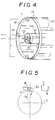
- FIG.5 shows in case of the outer current feeders 12.
- the Lorentz's force is depend on the thickness ho of current feeders under a constant magnetic field B and a constant electrode current J.
- T i 2JBh i r i where hi is the thickness of the inner current feeders and ri the inner radius of the thrust duct 2.
- FIG.6 show the thrust duct, introducing lead k and lead angle of the thrust duct defined by a longitudinal direction gain against one revolution of the thrust duct.
- the fluid 10 flows in relative direction of BD with its velocity Uc against the thrust duct.
- the velocity difference between the electromagnetic fluid 10 and the wall of the thrust duct 2 is Vc.
- the velocity difference between the electromagnetic fluid 10 and the wall of the thrust duct 2 is Uc which is smaller than Vc. Then the fluid frictional loss of rotating the thrust duct is able to be reduced greatly in comparison with the stationary thrust duct because of frictional loss being depend to square of the velocity difference.
- FIG 8 shows an embodiment called divided and stationary power busbar apparatus in comparison with the above embodiment called concentrate and rotatable power busbar apparatus.
- the power busbar apparatus 13,14 of the power supply device 3 have ringbusbars 21,22, respectively and are stationary structures in case of rotating the thrust duct 2.
- the sliding friction between stationary ring busbars 21,22 and rotatable current feeders 11,12 is so great.
- This type power busbar apparatus has the advantage of making the weight supporters and the power busbar apparatus in a body.
- the present invention is suitable for the ship propulsion system by generating thrust in the horizontal direction. And it is useful for Dynamic Positioning (DP) systems to produce the thrust in the horizontal and vertical directions. It is possible to be used as large sea water pumps, flowing sea water into filed EMTs and discharging from the duct. Using the reverse principle of EMTs, it is possible to use ocean currents (MHD) for power generators.
- DP Dynamic Positioning
Abstract
Description
- The present invention relates to a thrust generator which is a superconducting Electro Magnetic Thruster (hereinafter referred as EMT) of ship propulsion devices, a Dynamic Positioning System for ocean platforms and an Electro-Magnetic pump acting on an electrically conductive fluid, for example, sea water and a MHD generator and pumps and generators of pumping-up power systems. In the known systems, dipole, quadrupole, saddle and racetrack type superconducting magnets are used for EMTs. The conventional EMTs may however be too big and too heavy to gain enough thrust of full-scale ships because of low magnetic field of such magnets and of being difficult to construct. The magnetic field strength must be of the order of 10 to 20 Teslas to obtain enough propulsive efficiency of EMT ships. The EMT having such strong magnetic fields may be a huge one while an on-board EMT propulsion device is limited as to its size and its weight because of restriction of hull space. Hitherto, it has not been possible to realize EMT propulsion units with a satisfactory size, weight, thrust force and high magnetic field. In view of this, there is an important technical problem to develop EMTs for practical use.
- The previous invention by the inventor, PCT/JP89/01153, (see copending European patent application EP-A-0 453 567), had the purpose of supplying light weight and compact thrust superconducting magnets. According to the previous invention, the superconducting EMT generator comprises a superconducting solenoid magnet, a power supply device and a thrust duct having a spiral portion with a pair of electrodes inserted in the hollow interior of the superconducting solenoid coil magnet. Current feeders are provided for supplying current to said electrodes from said power supply device. The openings of the inlet and the outlet of the spiral duct are provided along the longitudinal center axis of the solenoid coil magnet. In the case of sea water as a conductive fluid flowing through the thrust duct, the anode or positive electrode, is arranged continuously on the radially inner side wall of the duct, and the cathode or negative electrode, is opposed to the outer side wall of the duct. A similar device is disclosed in FR-A-2 112 791.
- In the known thrust generator described above, the velocity of electromagnetic fluid flow becomes much greater so that the propulsive energy efficiency is decreasing rapidly, because of increasing greatly the frictional loss between the thrust duct wall and fluid.
- The present invention has the purpose of providing thrust generators with higher thrust and higher propulsive efficiency, reducing fluid frictional losses by matching the velocity of the thrust duct and one of fluid, by rotation of the thrust duct. This object is achieved by a thrust generator in accordance with claim 1.
- The thrust generator according to the invention has a structure wherein a helical duct is rotatably supported inside a hollow Portion of a superconducting magnet of a solenoid coil type, positive and negative electrodes are so bonded to the surface of the thrust duct as to permit the flow of an electromagnetic fluid such as sea water, and electric current is supplied from a current feeder to the electromagnetic fluid inside the thrust duct so as to generate a Lorentz's force with a magnetic fluid. The current feeders are mounted on the thrust duct at equal intervals. The Lorentz's force is also generated in each element of the current feeder by the magnetic field generated by the superconducting magnet and the electrode current flowing through each element, and rotates and drives the thrust duct.
- The thrust generator by the present invention has a power busbar apparatus, supplying the electric current into current feeders. The power busbar apparatus is made up of ringbars fixed at concentric center of the thrust duct and straight busbars in the longitudinal axis of the thrust duct, making contact with above current feeders.
- The power busbar apparatus can be divided into rotatable structure and stationary structure types. In the case of the rotatable structure type providing the ability to rotate with the thrust duct, the power busbar apparatus is fixed on the current feeders mounted in the thrust duct, and has slide terminals or roller terminals to make contact with the power supply generator. The roller type terminals provide making simple and compact structures and reducing sliding friction. In the case of the stationary structure type, the power busbar apparatus has ring busbars between stationary straight busbars of the power busbar apparatus In this type, the sliding friction is so large but makes the weight supporters and the power busbar apparatus in a body.
- In the case of sea water as a conductive fluid flowing in the thrust duct, anode is arrange on the inner side wall of the duct, and cathode is opposed to the outer side wall of the duct because of decreasing effective electrochemical reaction area of electrode by producing hydrogen bubbles at the cathode. It is possible to generate the maximum thrust in case of the ratio on 3.5 of outer radius to inner radius of the thrust duct.
-
- FIG.1 shows a cut-away drawing of a device adopting the present invention,
- FIG.2 shows an enlarged detail drawing,
- FIG.3 shows an a cross section along arrow III-III in FIG.1,
- FIG.4 shows a general layout illustration of a power busbar apparatus,
- FIG.5 shows Lorentz's force in a element of a current feeder,
- FIG.6 shows a velocity diagram between a rotational velocity of a thrust duct and a flow velocity of an electromagnets fluid,
- FIG.7 shows a frictional loss against a rotational velocity of a thrust duct, and
- FIG.8 shows an enlarged detail cross section of a second embodiment.
- Preferred embodiment of the present invention will now be described hereinafter referring accompanying drawings. The thrust generator of the present invention provides a superconducting solenoid coil magnet 1, a rotatable
spiral thrust duct 2 and apower supply device 3. The superconducting magnet 1 provides acoil 4 winded by superconducting wires to be set in a highly efficient thermal insulated container of a cryostat. The superconducting solenoid magnet generates so much strong magnetic field in thehollow interior 5 of the magnet. Thesuperconducting solenoid magnet 4 is operating in the persistent current mode or by connecting with power supply lines. The winding concept of thesuperconducting solenoid magnet 4 may be a pancake type or a layered type. - The
thrust duct 2 is a rotatable spiral hollow one with rectangular cross section. The spiral portion of thethrust duct 2 is inserted in the hollow interior of the superconducting solenoid magnet 1. Both of aninlet 6 and an outlet 7, each having an opening 6a, 7a, of thethrust duct 2 extend along thelongitudinal center axis 1a of the superconducting solenoid magnet 1. There is however no restriction concerning with cross section form of thethrust duct 2 in the present invention. The thrust duct is supported by support devices such as rollers and so on. -
Electrodes thrust duct 2. In Fig.1 theanode 8 is arranged on the inner side wall of thethrust duct 2, and thecathode 9 is opposed to the outer side wall of thethrust duct 2 because of decreasing effective electrochemical reaction area of thecathode 9 by producing hydrogen bubbles. The present invention is not restricted concerning with arrangements of electrodes. - The
power supply device 3 consists of plural current feeders 11.12 andpower busbar apparatus thrust duct 2, the innercurrent feeders 11 are set at interval of 90 degree. In the portion between outside of thethrust duct 2 and inside of the superconducting solenoid magnet 1, outercurrent feeders 12 are set at interval of 45 degree. Each ofcurrent feeders thrust duct 2, contacting with inner current feeders toanode 8, contacting with outer current feeders tocathode 9. - The inner
power busbar apparatus 13 is made up of asmall ringbar 15 and fourstraight busbars 16,... extending from theringbar 15. Theringbar 15 is placed in concentric center of thethrust duct 2, making contact withroller terminals ringbar 15. Thestraight busbar 16 is inserted into the inside portion of thethrust duct 2 at the corresponding position to the innercurrent feeders 11, its length being along the longitudinal axis of thethrust duct 2, making contact with all innercurrent feeders 11. - The outer
power busbar apparatus 14 is made up of alarge ringbar 18 and eightstraight busbars 19 extending from theringbar 18. Theringbar 18 is placed in concentric center of thethrust duct 2, making contact withroller terminals 20,... in the inner wall of theringbar 18. Thestraight busbar 19 is inserted into the outside portion of thethrust duct 2 at the corresponding position to the outercurrent feeders 12, its length being along the longitudinal axis of thethrust duct 2, making contact with all innercurrent feeders 12. - In the present embodiment the electrode current is supplied from the
roller terminals power busbar apparatus 13, to theringbar 15, to the fourstraight bursars 16, to the innercurrent feeders 11, to theanode 8, and at last into theelectromagnetic fluid 10. The supplied electrode current flows from theelectromagnetic fluid 10, to thecathode 9, to outercurrent feeders 12, tostraight busbars 19, to theringbar 18, to theroller terminals 20. - In FIG.2, the reaction between the magnetic field B generated by the fixed superconducting solenoid magnet 1 and the electric current J passing through the sea water from
anode 8 tocathode 9 generates a Lorentz's force F whose direction is shown by arrow. Theelectromagnetic fluid 10 flows into thethrust duct 2 through anopening 6a at theinlet end portion 6. is pressed continuously the Lorentz's force F inside thethrust duct 2, is accelerated by this force and is jetted outside from anopening 7a at the outlet end portion 7. The reaction of the jet force becomes a thrust. - Now introducing the electrode current J (A), the electrode voltage V (V), the input electric power P (W) is calculated from the following equations,


where; - j:
- Electric current density at the reference radius rc(A/m²)
- rc:
- Reference radius ( ri + ro )/2 (m)
- ro:
- Outer radius of the thrust duct (m)
- ri:
- Inner radius of the thrust duct (m)
- b:
- Cell length of the thrust duct (m)
- n:
- .Number of cell of the thrust duct
- 1:
- Overall length of the thrust duct (m)
- σ:
- Sea water electric conductivity (S/m)
- In a similar way, the Lorentz's force f is also generated in each element of inner and outer
current feeders thrust duct 2. - Now it will be described in the followings about the rotating force generating in each element of current feeders in FIG. 5. FIG.5 shows in case of the outer
current feeders 12. - Supposing the dimension of element, like as FIG.5, w(m) in width, ho (m) in thickness, d (m) in length, the average current density j is obtained from followings,

and the Lorentz force density fo due to the magnetic field B is,
The Lorentz's force fe per one outer current feeder is given the following,
As the results, the total Lorentz's force Fe acting on (m x n) current feeders is,
In the present analysis, the Lorentz's force is depend on the thickness ho of current feeders under a constant magnetic field B and a constant electrode current J. The rotating moment To acting on thethrust duct 2 is calculated from the followings,
By the same way, the rotating moment Ti by the inner current feeders is obtained.
where hi is the thickness of the inner current feeders and ri the inner radius of thethrust duct 2. - The resultant rotating moment T acting on the thrust duct is calculated from the following equation,

- For example, in the case of electrode current J=4000(A), magnetic field B=10(T), inner radius of the thrust duct ri=0.228(m), outer radius of the thrust duct ro=0.8(m) and thickness of current feeders hi=ho=0.1(m), the inner, outer and total rotating moment acting the thrust duct are computed, respectivety,


- FIG.6 show the thrust duct, introducing lead k and lead angle of the thrust duct defined by a longitudinal direction gain against one revolution of the thrust duct. Now supposing the condition of frictionless or slip between fluid and the wall of the thrust duct, of being uniform and steady flow, and of the thrust duct being stationary, the
electromagnetic fluid 10 flows in direction ofOA with its velocity Vc. And now, rotating the thrust duct in circular direction ofOB with its velocity Cc, theelectromagnetic fluid 10 is pressed by the wall of thethrust duct 2 and moves in direction ofAD , its moving velocity Cc tan(β), where tan(β)=k/(2πrc ). Then in view of a stationary coordinate, the fluid 10 flows in absolute direction ofOD with its velocity Wc. On the other hand, in a rotative coordinate of the rotating thrust duct, the fluid 10 flows in relative direction ofBD with its velocity Uc against the thrust duct. Here the velocity Uc is calculated from the followings,

- That is, in the case of the
thrust duct 2 being stationary, the velocity difference between theelectromagnetic fluid 10 and the wall of thethrust duct 2 is Vc. In the case of thrust duct rotating with the circular velocity Cc, the velocity difference between theelectromagnetic fluid 10 and the wall of thethrust duct 2 is Uc which is smaller than Vc. Then the fluid frictional loss of rotating the thrust duct is able to be reduced greatly in comparison with the stationary thrust duct because of frictional loss being depend to square of the velocity difference. - Here introducing an angular velocity ω, the revolution n (rpm) of the thrust duct in order to obtain the circular velocity Cc is gained by the following relation,


And the ratio of Uc to Vc, so that the ratio of diminution of frictional loss is given by the following relation
The calculated results are plotted in FIG.7. FIG.7 shows that, for example, supposing that the circular velocity of thethrust duct 2 is 80 percent of the flow velocity of electromagnetic fluid and that the lead angle is = 30°, the ratio of diminution of frictional loss is about 90 percent. - FIG 8 shows an embodiment called divided and stationary power busbar apparatus in comparison with the above embodiment called concentrate and rotatable power busbar apparatus. In this embodiment, the
power busbar apparatus power supply device 3 have ringbusbars 21,22, respectively and are stationary structures in case of rotating thethrust duct 2. In this type, the sliding friction betweenstationary ring busbars current feeders - It is possible that a pair of superconducting solenoid magnets are arranged in row, making closed loop magnetic flux line, resulting in magnetic flux density generated by a pair of superconducting magnets being so much stronger than a single superconducting magnet, as showing in the previous invention. PCT/JP89/01153.
- The present invention is suitable for the ship propulsion system by generating thrust in the horizontal direction. And it is useful for Dynamic Positioning (DP) systems to produce the thrust in the horizontal and vertical directions. It is possible to be used as large sea water pumps, flowing sea water into filed EMTs and discharging from the duct. Using the reverse principle of EMTs, it is possible to use ocean currents (MHD) for power generators.
The Lorentz's force F (N) is calculated from the following relation,

Substituting the Lorentz's force relation into the input power equation,
As the results,
where A is defined as follows,
The Maximum Lorentz's force is obtained when it is satisfied with the following relation.
The numerical solutions show that the maximum Lorentz's force is able to be gained when the thrust duct dimension is satisfied with the relation, ro = 3.5 ri. The experimental results supported the analytic results.
Claims (6)
- Thrust generator comprising a superconducting solenoid magnet (1), a power supply device (3), and a thrust duct (2) having a spiral portion inserted in a hollow interior of said superconducting solenoid magnet, an anode (8) being fixed continuously in a radially inner side wall of said thrust duct, a cathode (9) being arranged continuously in an opposite side wall, inner (11) and outer (12) current feeders being provided for supplying current from said power supply device to said anode (8) and cathode (9) respectively, openings (6a,7a) of inlet (6) and outlet (7) of said thrust duct (2) being provided along the center axis of said superconducting magnet, characterised in that said inner (11) and outer (12) current feeders are disposed equiangularly over the respective duct walls, and in that the duct (2) is mounted for rotation about the said center axis by Lorentz's force generated in said current feeders.
- Thrust generator according to claim 1, wherein said power supply device (3) comprises a power busbar apparatus (13,14) supplying electric current to said current feeders (11,12), said power busbar apparatus comprising a ringbar (15,18) in concentric center of said thrust duct and a straight busbar (16,19) extended from said ringbar, making contact with said current feeder.
- Thrust generator according to claim 2, wherein said power busbar apparatus (13,14) is fixed to said current feeder (11,12), having the ability to rotate with said thrust duct (2).
- Thrust generator according to claim 3, wherein a supply terminal (17,20) from the power supply device (3) makes contact with an inner wall or an outer wall of said ringbar (15,18).
- Thrust generator according to claim 2, wherein said power busbar apparatus (13,14) has a ring busbar (21,22) between said current feeder (11,12) and said straight busbar (16,19), the straight busbar, being fixed at a stationary position.
- Thrust generator according to anyone of claims 1 to 5, wherein the ratio of the outer radius to the inner radius of said thrust duct (2) is about 3.5.
Applications Claiming Priority (3)
| Application Number | Priority Date | Filing Date | Title |
|---|---|---|---|
| JP2253380A JP3045754B2 (en) | 1990-09-21 | 1990-09-21 | Thrust generator |
| JP253380/90 | 1990-09-21 | ||
| PCT/JP1991/001250 WO1992005621A1 (en) | 1990-09-21 | 1991-09-20 | Thrust generator |
Publications (3)
| Publication Number | Publication Date |
|---|---|
| EP0500970A1 EP0500970A1 (en) | 1992-09-02 |
| EP0500970A4 EP0500970A4 (en) | 1993-02-24 |
| EP0500970B1 true EP0500970B1 (en) | 1995-04-12 |
Family
ID=17250559
Family Applications (1)
| Application Number | Title | Priority Date | Filing Date |
|---|---|---|---|
| EP91916612A Expired - Lifetime EP0500970B1 (en) | 1990-09-21 | 1991-09-20 | Thrust generator |
Country Status (5)
| Country | Link |
|---|---|
| US (1) | US5298818A (en) |
| EP (1) | EP0500970B1 (en) |
| JP (1) | JP3045754B2 (en) |
| DE (1) | DE69108891T2 (en) |
| WO (1) | WO1992005621A1 (en) |
Cited By (3)
| Publication number | Priority date | Publication date | Assignee | Title |
|---|---|---|---|---|
| DE102004044539A1 (en) * | 2004-09-10 | 2006-03-30 | Technische Universität Dresden | Electromagnetic pump for chemical industry applications has coils between electrodes embedded in pipe walls |
| CN109030850A (en) * | 2018-09-20 | 2018-12-18 | 天津大学 | A kind of MHD angular-rate sensor stablizes the driving device in modulation magnetic field |
| CN111361720A (en) * | 2020-03-26 | 2020-07-03 | 中国科学院电工研究所 | Integrated magnetofluid propeller |
Families Citing this family (20)
| Publication number | Priority date | Publication date | Assignee | Title |
|---|---|---|---|---|
| EP0749644A1 (en) * | 1994-12-30 | 1996-12-27 | Edward Benton | Specifications for the pulsed field flux engine |
| US5668420A (en) * | 1995-04-06 | 1997-09-16 | The Penn State Research Foundation | Magnetohydrodynamic apparatus |
| EP0931931A1 (en) * | 1998-01-27 | 1999-07-28 | Entry-Technology | Magneto hydro dynamical tidal and ocean current converter |
| US6342071B1 (en) * | 1999-07-08 | 2002-01-29 | Benjamin David Pless | Ambulatory blood pump |
| US6352455B1 (en) | 2000-06-22 | 2002-03-05 | Peter A. Guagliano | Marine propulsion device |
| US7445531B1 (en) | 2003-08-25 | 2008-11-04 | Ross Anthony C | System and related methods for marine transportation |
| US20060070371A1 (en) * | 2004-10-05 | 2006-04-06 | St Clair John Q | Electric dipole moment propulsion system |
| US9597615B2 (en) | 2005-02-15 | 2017-03-21 | Spiroflo Holdings, Inc. | Flow development chamber and separator |
| US7663261B2 (en) * | 2005-02-15 | 2010-02-16 | Spiroflo, Inc. | Flow development and cogeneration chamber |
| DE102005058729A1 (en) * | 2005-12-08 | 2007-06-14 | Technische Universität Ilmenau | Apparatus and method for the electromagnetic influence of the flow of low-conductivity and high-viscosity fluids |
| WO2013082578A1 (en) * | 2011-12-03 | 2013-06-06 | Thomas Krupenkin | Method and apparatus for mechanical energy harvesting using combined magnetic and microfluidic energy generation |
| US9259047B2 (en) * | 2012-09-13 | 2016-02-16 | Thomas Nikita Krupenkin | Apparatus for footwear-embedded mechanical energy harvesting system based on dual-loop channel |
| CN103117640A (en) * | 2013-03-14 | 2013-05-22 | 周华 | Magnetic fluid double-current generator |
| US9543818B2 (en) * | 2013-09-15 | 2017-01-10 | The Boeing Company | Ferrofluid motor |
| US20150145257A1 (en) * | 2013-11-25 | 2015-05-28 | Bryan P. Hendricks | Energy generating apparatus for gas or liquid flowing conditions |
| KR101860895B1 (en) * | 2017-02-27 | 2018-06-29 | 울산과학기술원 | Apparatus for transferring (electrically) conductive meterials |
| CN109639095B (en) * | 2019-01-24 | 2020-10-30 | 中国科学院电工研究所 | Spiral channel direct current magnetofluid pump |
| CN110550174B (en) * | 2019-09-25 | 2020-07-07 | 中国科学院电工研究所 | Multi-spiral-channel annular superconducting magnetofluid propeller |
| RU2751728C1 (en) * | 2020-08-31 | 2021-07-16 | Борис Клавдиевич Никитин | Silent hydraulic propulsion apparatus |
| CN112591067B (en) * | 2020-12-17 | 2022-05-10 | 淮安普乐菲智能科技有限公司 | Controllable bidirectional jet propeller |
Family Cites Families (6)
| Publication number | Priority date | Publication date | Assignee | Title |
|---|---|---|---|---|
| FR2112791A5 (en) * | 1970-11-09 | 1972-06-23 | Alsthom | Electromagnetic pump - needs no moving part to convey liquid which conducts electricity |
| JPS5519636A (en) * | 1978-07-25 | 1980-02-12 | Kawasaki Heavy Ind Ltd | Electromagnetic propulsion device for shipping |
| JPS583565A (en) * | 1981-06-27 | 1983-01-10 | Tanemi Notoko | Electric rotary machine |
| JPH0684159B2 (en) * | 1985-09-18 | 1994-10-26 | 株式会社前川製作所 | Propulsion device for seawater vessels |
| WO1990014265A1 (en) * | 1989-05-24 | 1990-11-29 | Laukien Guenther | Process and device for marine propulsion |
| ATE105447T1 (en) * | 1989-11-10 | 1994-05-15 | Muroya Masaaki | SCHUBERGEN. |
-
1990
- 1990-09-21 JP JP2253380A patent/JP3045754B2/en not_active Expired - Lifetime
-
1991
- 1991-09-20 DE DE69108891T patent/DE69108891T2/en not_active Expired - Fee Related
- 1991-09-20 EP EP91916612A patent/EP0500970B1/en not_active Expired - Lifetime
- 1991-09-20 WO PCT/JP1991/001250 patent/WO1992005621A1/en active IP Right Grant
- 1991-09-20 US US07/858,986 patent/US5298818A/en not_active Expired - Fee Related
Cited By (4)
| Publication number | Priority date | Publication date | Assignee | Title |
|---|---|---|---|---|
| DE102004044539A1 (en) * | 2004-09-10 | 2006-03-30 | Technische Universität Dresden | Electromagnetic pump for chemical industry applications has coils between electrodes embedded in pipe walls |
| DE102004044539B4 (en) * | 2004-09-10 | 2008-08-28 | Technische Universität Dresden | Device for moving electrically conductive liquid media |
| CN109030850A (en) * | 2018-09-20 | 2018-12-18 | 天津大学 | A kind of MHD angular-rate sensor stablizes the driving device in modulation magnetic field |
| CN111361720A (en) * | 2020-03-26 | 2020-07-03 | 中国科学院电工研究所 | Integrated magnetofluid propeller |
Also Published As
| Publication number | Publication date |
|---|---|
| DE69108891T2 (en) | 1995-08-24 |
| EP0500970A4 (en) | 1993-02-24 |
| JP3045754B2 (en) | 2000-05-29 |
| DE69108891D1 (en) | 1995-05-18 |
| EP0500970A1 (en) | 1992-09-02 |
| WO1992005621A1 (en) | 1992-04-02 |
| US5298818A (en) | 1994-03-29 |
| JPH04133656A (en) | 1992-05-07 |
Similar Documents
| Publication | Publication Date | Title |
|---|---|---|
| EP0500970B1 (en) | Thrust generator | |
| US4906877A (en) | MHD generator and fluid pump | |
| US9866097B2 (en) | High speed turbine | |
| EP1902511B1 (en) | Superconducting acyclic homopolar electromechanical power converter | |
| US4808079A (en) | Magnetic pump for ferrofluids | |
| KR20170023943A (en) | Electromagnetic device | |
| US5668420A (en) | Magnetohydrodynamic apparatus | |
| US9762094B2 (en) | Low speed electromagnetic turbine | |
| US5352139A (en) | Method and apparatus for the propulsion of water vehicles | |
| US20050285452A1 (en) | Linear motor geometry for use with persistent current magnets | |
| US5314311A (en) | Thrust generator | |
| JPH04500898A (en) | Method and device for driving ships | |
| US3106058A (en) | Propulsion system | |
| US8575790B1 (en) | Superconducting electrodynamic turbine | |
| CN108539959B (en) | Magnet rotating device, method for stably rotating magnet and magnetic brake system | |
| US6318666B1 (en) | Superconductive geomagnetic craft | |
| EP3891392A1 (en) | Generation of electromagnetic solitons for propulsion by a rotating anisotropic homopolar magnetic field | |
| US20230391478A1 (en) | Magnetic Flux Engine for Spacecraft Propulsion | |
| Font et al. | Magnetohydrodynamic propulsion for the classroom | |
| JP2736469B2 (en) | Thrust generator | |
| JPH03235796A (en) | Propulsion device for superconduction electromagnetic propulsion ship | |
| JPH01109195A (en) | Electromagnetic propulsion device | |
| JPH0736691B2 (en) | Electromagnetic force generator | |
| JPH1111388A (en) | Electromagnetic propulsion device | |
| EP0275659A1 (en) | Attitude control actuator |
Legal Events
| Date | Code | Title | Description |
|---|---|---|---|
| PUAI | Public reference made under article 153(3) epc to a published international application that has entered the european phase |
Free format text: ORIGINAL CODE: 0009012 |
|
| 17P | Request for examination filed |
Effective date: 19920529 |
|
| AK | Designated contracting states |
Kind code of ref document: A1 Designated state(s): DE FR GB SE |
|
| A4 | Supplementary search report drawn up and despatched |
Effective date: 19930107 |
|
| AK | Designated contracting states |
Kind code of ref document: A4 Designated state(s): DE FR GB SE |
|
| 17Q | First examination report despatched |
Effective date: 19940531 |
|
| GRAA | (expected) grant |
Free format text: ORIGINAL CODE: 0009210 |
|
| AK | Designated contracting states |
Kind code of ref document: B1 Designated state(s): DE FR GB SE |
|
| REF | Corresponds to: |
Ref document number: 69108891 Country of ref document: DE Date of ref document: 19950518 |
|
| ET | Fr: translation filed | ||
| PLBE | No opposition filed within time limit |
Free format text: ORIGINAL CODE: 0009261 |
|
| STAA | Information on the status of an ep patent application or granted ep patent |
Free format text: STATUS: NO OPPOSITION FILED WITHIN TIME LIMIT |
|
| 26N | No opposition filed | ||
| PGFP | Annual fee paid to national office [announced via postgrant information from national office to epo] |
Ref country code: GB Payment date: 20010823 Year of fee payment: 11 |
|
| PGFP | Annual fee paid to national office [announced via postgrant information from national office to epo] |
Ref country code: FR Payment date: 20010921 Year of fee payment: 11 |
|
| PGFP | Annual fee paid to national office [announced via postgrant information from national office to epo] |
Ref country code: SE Payment date: 20010925 Year of fee payment: 11 |
|
| PGFP | Annual fee paid to national office [announced via postgrant information from national office to epo] |
Ref country code: DE Payment date: 20010927 Year of fee payment: 11 |
|
| REG | Reference to a national code |
Ref country code: GB Ref legal event code: IF02 |
|
| PG25 | Lapsed in a contracting state [announced via postgrant information from national office to epo] |
Ref country code: GB Free format text: LAPSE BECAUSE OF NON-PAYMENT OF DUE FEES Effective date: 20020920 |
|
| PG25 | Lapsed in a contracting state [announced via postgrant information from national office to epo] |
Ref country code: SE Free format text: LAPSE BECAUSE OF NON-PAYMENT OF DUE FEES Effective date: 20020921 |
|
| PG25 | Lapsed in a contracting state [announced via postgrant information from national office to epo] |
Ref country code: DE Free format text: LAPSE BECAUSE OF NON-PAYMENT OF DUE FEES Effective date: 20030401 |
|
| EUG | Se: european patent has lapsed | ||
| GBPC | Gb: european patent ceased through non-payment of renewal fee |
Effective date: 20020920 |
|
| PG25 | Lapsed in a contracting state [announced via postgrant information from national office to epo] |
Ref country code: FR Free format text: LAPSE BECAUSE OF NON-PAYMENT OF DUE FEES Effective date: 20030603 |
|
| REG | Reference to a national code |
Ref country code: FR Ref legal event code: ST |