EP0501648A2 - In bundle foreign object search and retrieval apparatus - Google Patents
In bundle foreign object search and retrieval apparatus Download PDFInfo
- Publication number
- EP0501648A2 EP0501648A2 EP92301296A EP92301296A EP0501648A2 EP 0501648 A2 EP0501648 A2 EP 0501648A2 EP 92301296 A EP92301296 A EP 92301296A EP 92301296 A EP92301296 A EP 92301296A EP 0501648 A2 EP0501648 A2 EP 0501648A2
- Authority
- EP
- European Patent Office
- Prior art keywords
- flexible member
- cable
- flexible
- distal end
- difficult
- Prior art date
- Legal status (The legal status is an assumption and is not a legal conclusion. Google has not performed a legal analysis and makes no representation as to the accuracy of the status listed.)
- Granted
Links
Images


Classifications
-
- G—PHYSICS
- G21—NUCLEAR PHYSICS; NUCLEAR ENGINEERING
- G21F—PROTECTION AGAINST X-RADIATION, GAMMA RADIATION, CORPUSCULAR RADIATION OR PARTICLE BOMBARDMENT; TREATING RADIOACTIVELY CONTAMINATED MATERIAL; DECONTAMINATION ARRANGEMENTS THEREFOR
- G21F1/00—Shielding characterised by the composition of the materials
-
- F—MECHANICAL ENGINEERING; LIGHTING; HEATING; WEAPONS; BLASTING
- F22—STEAM GENERATION
- F22B—METHODS OF STEAM GENERATION; STEAM BOILERS
- F22B37/00—Component parts or details of steam boilers
- F22B37/02—Component parts or details of steam boilers applicable to more than one kind or type of steam boiler
- F22B37/48—Devices for removing water, salt, or sludge from boilers; Arrangements of cleaning apparatus in boilers; Combinations thereof with boilers
- F22B37/483—Devices for removing water, salt, or sludge from boilers; Arrangements of cleaning apparatus in boilers; Combinations thereof with boilers specially adapted for nuclear steam generators
-
- B—PERFORMING OPERATIONS; TRANSPORTING
- B25—HAND TOOLS; PORTABLE POWER-DRIVEN TOOLS; MANIPULATORS
- B25J—MANIPULATORS; CHAMBERS PROVIDED WITH MANIPULATION DEVICES
- B25J18/00—Arms
- B25J18/06—Arms flexible
-
- F—MECHANICAL ENGINEERING; LIGHTING; HEATING; WEAPONS; BLASTING
- F22—STEAM GENERATION
- F22B—METHODS OF STEAM GENERATION; STEAM BOILERS
- F22B37/00—Component parts or details of steam boilers
- F22B37/002—Component parts or details of steam boilers specially adapted for nuclear steam generators, e.g. maintenance, repairing or inspecting equipment not otherwise provided for
-
- F—MECHANICAL ENGINEERING; LIGHTING; HEATING; WEAPONS; BLASTING
- F28—HEAT EXCHANGE IN GENERAL
- F28G—CLEANING OF INTERNAL OR EXTERNAL SURFACES OF HEAT-EXCHANGE OR HEAT-TRANSFER CONDUITS, e.g. WATER TUBES OR BOILERS
- F28G1/00—Non-rotary, e.g. reciprocated, appliances
- F28G1/16—Non-rotary, e.g. reciprocated, appliances using jets of fluid for removing debris
- F28G1/166—Non-rotary, e.g. reciprocated, appliances using jets of fluid for removing debris from external surfaces of heat exchange conduits
-
- F—MECHANICAL ENGINEERING; LIGHTING; HEATING; WEAPONS; BLASTING
- F28—HEAT EXCHANGE IN GENERAL
- F28G—CLEANING OF INTERNAL OR EXTERNAL SURFACES OF HEAT-EXCHANGE OR HEAT-TRANSFER CONDUITS, e.g. WATER TUBES OR BOILERS
- F28G15/00—Details
- F28G15/04—Feeding and driving arrangements, e.g. power operation
Definitions
- the present invention relates generally to a robotic system that is useful in nuclear power plants and other structures with a difficult to access geometry. More particularly, it relates to such a system which is capable of locating and removing foreign objects that have been accidentally introduced into such structures with a difficult to access geometry, such as in the tube bundles of a nuclear power plant's steam generators.
- Nuclear power generation equipment consists of two major parts, the reactor and the steam generator.
- the steam generator includes a heat exchanger, which, in simple terms, consists of a bundle of thin wall tubes, which are tightly spaced and arranged in a matrix-like fashion. The spacing between the tubes is less than 0.5 inches, and the tube height extends to several feet. Hot reactor coolant is pumped through the tubes, which in turn heats water under pressure above the boiling point to several hundred degrees, thus generating steam.
- U.S. Patent 4,638,667 issued January 27, 1987 to Zimmer et al. discloses a remote probe positioning apparatus including a flexible tape which has an optical fiber cable running the length of the tape and a retractor tool at a distal end of the tape.
- a retractor tool at a distal end of the tape.
- no details are given on the construction and operation of the retractor tool. Further development is therefore required in order to provide a system for removing foreign objects which will meet the needs of nuclear power plant steam generator geometry and similar difficult to access geometries.
- a foreign object search and retrieval apparatus in accordance with one aspect of the invention has a flexible member a distal end.
- An optical cable extends lengthwise along and within the flexible member.
- a video cable and a video camera connected to the video cable at the distal end of the flexible member forms an image of a scene visible from the distal end of the flexible member for transmission by the video cable.
- a retractor tool is mounted at the distal end of the flexible member. At least one actuating cable for the retractor tool extends lengthwise along and within the flexible member.
- the flexible member is configured to be driven into the difficult to access geometry.
- a positioning handle is connected to the at least one actuating cable for the retractor tool.
- the positioning handle includes a joystick mechanism and the at least one actuating cable for the retractor tool includes a plurality of flexible steering cables connected to the joystick mechanism and to the retractor tool.
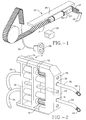
- Figure 1 is a perspective view of a foreign object search and retrieval apparatus in accordance with the invention.
- Figure 2 is a perspective view of a portion of the apparatus shown in Figure 1.
- Figures 3A and 3B are perspective views of a further portion of the apparatus shown in Figures 1 and 2 in use.
- Figure 4 is in part a perspective view and in part a block diagram of another embodiment of a foreign object search and retrieval apparatus in accordance with the invention.
- Figure 4A is an enlarged side view of a portion of the apparatus of Figure 4
- Figure 5 is a plan view of the apparatus of Figures 4 and 4A in use.
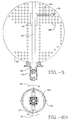
- Figures 6A and 6B are cross-section and end views, respectively, of a user control for the apparatus of Figures 4-5.
- Figures 7A and 7B are cross-section and end views, respectively, of a portion of the apparatus of Figures 4-5.
- Figure 8 is a cross-section view of another portion of the apparatus of Figures 4-7B.
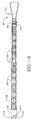
- Figure 9 is a side view of another portion of the apparatus of Figures 4-7B.
- the apparatus 10 utilizes a flexible lance 12 formed of individual hose bar segments 14 strung on cables 16 to give a structure that is flexible along its length and fairly rigid in a direction transverse to its length. Further details on the construction of the lance 12 are provided in the above referenced copending Ruggieri et al. application, the disclosure of which is hereby incorporated by reference herein. Extending from working channels 18 of nozzle block 20 of the lance 12 are a pair of multi-prong retrievers 22. A miniaturized Videoprobe camera 24 is provided in the nozzle block 20 between the two retrievers 22.
- the retrievers are each connected to an actuating cable 26, which extends through the flexible lance 12 to a manual control 28.
- the camera 24 is connected by a cable 30 to suitable video processing circuits (not shown) for generation of images on a video display 32.
- the cable 30 also houses a fiber optic bundle which conveys light to the area being serviced by the lance 12.
- the flexible lance 12 extends through a transporter 34, which positions the nozzle block end of the lance 12 opposite a portion of a steam generator or other difficult to access geometry.
- the transporter 34 moves along a transport rail 36 to move the nozzle block end of the lance 12 into position.
- the lance 12 is then advanced through the transporter 34 by means of a sprocket drive 37 that has teeth which fit between the hosebar segments 14 to move the nozzle block end into the difficult to access geometry and retracted to withdraw the nozzle block end from the difficult to access geometry.
- Figures 3A and 3B show how the retrievers 22 are operated to retrieve a foreign object, such as a welding rod 38, after the nozzle block 20 end of the flexible lance 12 is positioned as desired in tubes 40 of the steam generator.
- the actuating cable 26 of one of the retrievers 22 is extended from the nozzle block 20, so that its retriever 22 is able to grasp the welding rod 38.
- the actuating cable 26 is then rotated, as indicated by arrow 42, to upend the welding rod 38 to the position shown in Figure 3B.
- the other actuating cable 26 is then extended, so that the other retriever 22 grasps the welding rod 38.
- the flexible lance 12 is then withdrawn from the tube 40 bundle, as indicated by arrows 44, thus removing the welding rod 38.
- Figures 4 and 5 show another system 50 for the location and removal of foreign objects from a difficult to access geometry, i.e., steam generator 52.
- a flexible lance 54 having the same construction as the flexible lance 12 extends through a robot cylinder 56, which is mounted for movement along track 58.
- the flexible lance 54 extends through hand hole 60, around a reel 62 and a take-up reel 64 to manipulator handles 66.
- the reels 62 and 64 are mounted on a "goal post"support 68, positioned at the hand hole 60.
- Robot driving power supply and controls 70 are connected to the flexible lance 54 at the manipulator handles 66.
- a video monitor 72 is mounted on the support 68 and is connected to receive images from a miniaturized Videoprobe camera 74 in nozzle block 76 of the flexible lance 54.
- the flexible lance 54 has a multi-prong retriever 78 connected to an actuating cable 80 and another multi-prong retrieval tool 82 having a different configuration connected to an actuating cable 84.
- a variety of retrieval tool configurations can be employed with the flexible lance 54, depending on the nature of the foreign objects to be retrieved.
- a portable bucket 86 is positioned inside the steam generator 52 adjacent to the hand hole 60.
- the robot controls 70 In operation of the system 50, one operator mans the robot controls 70 and another operator mans the tool manipulating handles 66.
- the video camera 74 provides a 90 degree viewing field. It is used by both operators to position the nozzle block 76 end of the flexible lance 54 accurately and sequentially and to retrieve objects, respectively.
- the robot controls 70 operator positions the robot cylinder 56 with the flexible lance 54 opposite a point between two tube 88 rows and extends the lance 54, searching for foreign objects, such as washer 90. If none are found, the lance 54 is retracted, the cylinder 56 is rotated as indicated by arrow 92, and the procedure is repeated to inspect the opposite side from the track 58.
- the operator manning the tool manipulator 66 directs the appropriate tool 78 or 82 toward the object 90 and retrieves it.
- the robot controls 70 operator then retracts the lance and rotates the cylinder 56 so that the nozzle block 76 faces downwards.
- the cylinder 56 is then retracted to a position directly above the bucket 86.
- the object 90 is released into the bucket 86, and the searching process continues.
- the above operation could be carried out with a single operator, by sequential operation of the controls 70 and tool manipulator 66.
- the tool manipulator 66 could be replaced with a system of motors and appropriate controls, so that one operator can perform the search and retrieval remotely. That embodiment would minimize the exposure of personnel to radiation.
- FIGS. 6A and 6B show details of the manipulator handles 66.
- a separate manipulator handle 66 is connected to each of the retrieval tools 78 and 82.
- the manipulator handle 66 will be explained with respect to the multi-prong retriever 78, it being understood that the manipulator handle 66 functions in a similar manner with the retrieval tool 82 and other retrieval tools.
- the manipulator handle 66 has a first handle portion 100 and a second handle portion 102 slideably mounted in the first handle portion 100.
- the manipulator handle 66 is fixedly attached to a base plate assembly 104.
- the base plate assembly is in turn attached to a rigid joint 106 on cover cage 108 by shaft 109.
- the cover cage 108 engages projections 110 on the base plate assembly 104 to prevent rotation of the base plate assembly 104 when the manipulator handle 66 is rotated in use.
- the manipulator handle 66 is movable in a joystick fashion, as indicated in phantom in Figure 6A.
- a joystick motion limiter 114 is attached to the shaft 109 and is connected to the baseplate assembly 104 by a center compression spring 116.
- Four steering cables 118 (two of which are shown in Figure 6A) are connected to the top, bottom, right and left sides of the base plate assembly 104.
- the steering cables 118 extend through actuating cable 80 and are connected to the multi-prong gripper 78.
- actuating cable 80 When the actuating cable 80 is extended from the nozzle block 76 ( Figure 4A), joystick movement of the manipulator handle 66 pulls on one or more of the steering cables to move the extending end of the actuating cable 80 up, down, to the left or to the right to position the gripper 78.
- the base plate assembly 104 pulls on the bottom steering cable 118, steering the gripper 78 downward.
- the actuating cable 80 consists of a multi-lumen flexible plastic extrusion 120 encased in a spring like jacket 122.
- the steering cables 118 extend lengthwise along the extrusion 120 and are free to move within it.
- Also extending lengthwise along the extrusion 120 are a spring tempered tool operating wire 124 and a pair of tool rotating cables 126.
- the steering cables 118 extend through a metal interface 128 and are attached to housing 130 of the gripper 78. It can be seen that pulling on the upper steering cable 118 will bend the gripper 78 downward, and pulling on the lower steering cable 118 will bend the gripper 78 upward.
- Left and right steering cables 118 operate in a similar manner.
- the tool operating wire 124 also extends through the interface 128 and is attached to prongs 132 of the gripper 78.
- the prongs 132 are normally closed and retracted within the housing 130. Pushing on the tool operating wire 124 causes the prongs 132 to extend beyond the housing 130 and open. The prongs 132 are then closed around a foreign object by pulling on the tool operating wire 124, moving the prongs partially back into the housing 130 to close them.
- the tool rotating cables 126 are also free to move within the actuating cable 80 and are connected to the multiprong retriever 78 for rotating it clockwise and counterclockwise by pulling on the cables 126.
- Figure 9 shows details of the retrieval tool 82, including how it is connected to tool rotating cables 126.
- the tool rotating cable 126 extends partially around the retrieval tool 82, so that pulling on the tool rotating cable 126 shown causes the retrieval tool to rotate clockwise.
- Another tool rotating cable 126 is connected to the opposite side of the retrieval tool 82, and pulling on that tool rotating cable 126 causes the retrieval tool 82 to rotate counter-clockwise.
- steering cables 118 pass through a string of aluminum or plastic beads 138 extending from the extrusion 120 and are anchored at housing 140 of the retrieval tool. Pulling on the upper steering cable 118 forces the beads 138 upwards to raise the retrieval tool 82.
- Tool operating wire 124 is attached to grappler prongs 142 of the retrieval tool 82. Pushing or pulling on the tool operating wire 124 extends or retracts the prongs 142 from or into the housing 140 to open or close the grappler prongs 142.
- the grappler prongs 142 lock onto an object such as a washer or screw by forcing the prongs 142 to close as they are retracted part way into the housing 140.
- the system and method finds and retrieves foreign objects in a difficult to access geometry, such as the in bundle area of a nuclear power plant steam generator. Operation of the system and the method is controlled remotely.
- the remote controls for the system and method are configured to provide precise control inside the difficult to access geometry.
Abstract
Description
- The present invention relates generally to a robotic system that is useful in nuclear power plants and other structures with a difficult to access geometry. More particularly, it relates to such a system which is capable of locating and removing foreign objects that have been accidentally introduced into such structures with a difficult to access geometry, such as in the tube bundles of a nuclear power plant's steam generators.
- Nuclear power generation equipment consists of two major parts, the reactor and the steam generator. The steam generator includes a heat exchanger, which, in simple terms, consists of a bundle of thin wall tubes, which are tightly spaced and arranged in a matrix-like fashion. The spacing between the tubes is less than 0.5 inches, and the tube height extends to several feet. Hot reactor coolant is pumped through the tubes, which in turn heats water under pressure above the boiling point to several hundred degrees, thus generating steam.
- During reactor shut down for refueling or any other reason, repair and maintenance technicians enter various areas, one of which is the steam generator housing. During such entry, accidental dropping of such items as welding rods, washers, screws and the like is possible. Such items can cause damage to the thin wall tubes if they are not retrieved. Repairing, replacing or plugging such damaged tubes is very expensive, both in terms of the labor involved and required reactor shut down. To date, it has not been possible to retrieve such items, due to the physical constraints of the steam generator geometry and the presence of radiation.
- U.S. Patent 4,638,667, issued January 27, 1987 to Zimmer et al. discloses a remote probe positioning apparatus including a flexible tape which has an optical fiber cable running the length of the tape and a retractor tool at a distal end of the tape. However, no details are given on the construction and operation of the retractor tool. Further development is therefore required in order to provide a system for removing foreign objects which will meet the needs of nuclear power plant steam generator geometry and similar difficult to access geometries.
- Accordingly, it is an object of this invention to provide a system for finding and retrieving foreign objects in a difficult to access geometry, such as the in bundle area of a nuclear power plant steam generator.
- It is another object of the invention to provide such a system for finding and retrieving foreign objects in which operation of the system is controlled remotely.
- It is a further object of the invention to provide such a system in which remote controls for the system and method are configured to provide precise control inside the difficult to access geometry.
- The attainment of these and related objects may be achieved through use of the novel foreign object search and retrieval apparatus herein disclosed. A foreign object search and retrieval apparatus in accordance with one aspect of the invention has a flexible member a distal end. An optical cable extends lengthwise along and within the flexible member. A video cable and a video camera connected to the video cable at the distal end of the flexible member forms an image of a scene visible from the distal end of the flexible member for transmission by the video cable. A retractor tool is mounted at the distal end of the flexible member. At least one actuating cable for the retractor tool extends lengthwise along and within the flexible member. The flexible member is configured to be driven into the difficult to access geometry. A positioning handle is connected to the at least one actuating cable for the retractor tool. The positioning handle includes a joystick mechanism and the at least one actuating cable for the retractor tool includes a plurality of flexible steering cables connected to the joystick mechanism and to the retractor tool.
- The attainment of the foregoing and related objects, advantages and features of the invention should be more readily apparent to those skilled in the art, after review of the following more detailed description of an embodiment thereof, taken together with the drawings, in which:
- Figure 1 is a perspective view of a foreign object search and retrieval apparatus in accordance with the invention.
- Figure 2 is a perspective view of a portion of the apparatus shown in Figure 1.
- Figures 3A and 3B are perspective views of a further portion of the apparatus shown in Figures 1 and 2 in use.
- Figure 4 is in part a perspective view and in part a block diagram of another embodiment of a foreign object search and retrieval apparatus in accordance with the invention.
- Figure 4A is an enlarged side view of a portion of the apparatus of Figure 4
- Figure 5 is a plan view of the apparatus of Figures 4 and 4A in use.
- Figures 6A and 6B are cross-section and end views, respectively, of a user control for the apparatus of Figures 4-5.
- Figures 7A and 7B are cross-section and end views, respectively, of a portion of the apparatus of Figures 4-5.
- Figure 8 is a cross-section view of another portion of the apparatus of Figures 4-7B.
- Figure 9 is a side view of another portion of the apparatus of Figures 4-7B.
- Turning now to the drawings, more particularly to Figure 1 and 2, there is shown an
apparatus 10 for the location and removal of foreign objects from a difficult to access geometry. Theapparatus 10 utilizes aflexible lance 12 formed of individualhose bar segments 14 strung oncables 16 to give a structure that is flexible along its length and fairly rigid in a direction transverse to its length. Further details on the construction of thelance 12 are provided in the above referenced copending Ruggieri et al. application, the disclosure of which is hereby incorporated by reference herein. Extending fromworking channels 18 ofnozzle block 20 of thelance 12 are a pair ofmulti-prong retrievers 22. A miniaturizedVideoprobe camera 24 is provided in thenozzle block 20 between the tworetrievers 22. The retrievers are each connected to anactuating cable 26, which extends through theflexible lance 12 to amanual control 28. Thecamera 24 is connected by acable 30 to suitable video processing circuits (not shown) for generation of images on avideo display 32. Thecable 30 also houses a fiber optic bundle which conveys light to the area being serviced by thelance 12. Theflexible lance 12 extends through atransporter 34, which positions the nozzle block end of thelance 12 opposite a portion of a steam generator or other difficult to access geometry. Thetransporter 34 moves along atransport rail 36 to move the nozzle block end of thelance 12 into position. Thelance 12 is then advanced through thetransporter 34 by means of asprocket drive 37 that has teeth which fit between thehosebar segments 14 to move the nozzle block end into the difficult to access geometry and retracted to withdraw the nozzle block end from the difficult to access geometry. - Figures 3A and 3B show how the
retrievers 22 are operated to retrieve a foreign object, such as awelding rod 38, after thenozzle block 20 end of theflexible lance 12 is positioned as desired intubes 40 of the steam generator. Theactuating cable 26 of one of theretrievers 22 is extended from thenozzle block 20, so that itsretriever 22 is able to grasp thewelding rod 38. The actuatingcable 26 is then rotated, as indicated byarrow 42, to upend thewelding rod 38 to the position shown in Figure 3B. The other actuatingcable 26 is then extended, so that theother retriever 22 grasps thewelding rod 38. Theflexible lance 12 is then withdrawn from thetube 40 bundle, as indicated by arrows 44, thus removing thewelding rod 38. - Figures 4 and 5 show another
system 50 for the location and removal of foreign objects from a difficult to access geometry, i.e.,steam generator 52. In thesystem 50, aflexible lance 54 having the same construction as theflexible lance 12 extends through arobot cylinder 56, which is mounted for movement alongtrack 58. Theflexible lance 54 extends throughhand hole 60, around areel 62 and a take-up reel 64 to manipulator handles 66. Thereels support 68, positioned at thehand hole 60. Robot driving power supply andcontrols 70 are connected to theflexible lance 54 at the manipulator handles 66. Avideo monitor 72 is mounted on thesupport 68 and is connected to receive images from aminiaturized Videoprobe camera 74 innozzle block 76 of theflexible lance 54. Theflexible lance 54 has amulti-prong retriever 78 connected to anactuating cable 80 and anothermulti-prong retrieval tool 82 having a different configuration connected to anactuating cable 84. A variety of retrieval tool configurations can be employed with theflexible lance 54, depending on the nature of the foreign objects to be retrieved. Aportable bucket 86 is positioned inside thesteam generator 52 adjacent to thehand hole 60. - In operation of the
system 50, one operator mans the robot controls 70 and another operator mans the tool manipulating handles 66. Thevideo camera 74 provides a 90 degree viewing field. It is used by both operators to position thenozzle block 76 end of theflexible lance 54 accurately and sequentially and to retrieve objects, respectively. The robot controls 70 operator positions therobot cylinder 56 with theflexible lance 54 opposite a point between twotube 88 rows and extends thelance 54, searching for foreign objects, such aswasher 90. If none are found, thelance 54 is retracted, thecylinder 56 is rotated as indicated byarrow 92, and the procedure is repeated to inspect the opposite side from thetrack 58. - If an
object 90 is located, the operator manning thetool manipulator 66 directs theappropriate tool object 90 and retrieves it. The robot controls 70 operator then retracts the lance and rotates thecylinder 56 so that thenozzle block 76 faces downwards. Thecylinder 56 is then retracted to a position directly above thebucket 86. Theobject 90 is released into thebucket 86, and the searching process continues. If desired, the above operation could be carried out with a single operator, by sequential operation of thecontrols 70 andtool manipulator 66. Alternatively, thetool manipulator 66 could be replaced with a system of motors and appropriate controls, so that one operator can perform the search and retrieval remotely. That embodiment would minimize the exposure of personnel to radiation. - Figures 6A and 6B show details of the manipulator handles 66. A separate manipulator handle 66 is connected to each of the
retrieval tools multi-prong retriever 78, it being understood that the manipulator handle 66 functions in a similar manner with theretrieval tool 82 and other retrieval tools. The manipulator handle 66 has afirst handle portion 100 and asecond handle portion 102 slideably mounted in thefirst handle portion 100. The manipulator handle 66 is fixedly attached to abase plate assembly 104. The base plate assembly is in turn attached to a rigid joint 106 oncover cage 108 byshaft 109. Thecover cage 108 engagesprojections 110 on thebase plate assembly 104 to prevent rotation of thebase plate assembly 104 when the manipulator handle 66 is rotated in use. In addition to the rotation of the manipulator handle 66 as indicated byarrows 112, the manipulator handle 66 is movable in a joystick fashion, as indicated in phantom in Figure 6A. Ajoystick motion limiter 114 is attached to theshaft 109 and is connected to thebaseplate assembly 104 by acenter compression spring 116. Four steering cables 118 (two of which are shown in Figure 6A) are connected to the top, bottom, right and left sides of thebase plate assembly 104. - The
steering cables 118 extend throughactuating cable 80 and are connected to themulti-prong gripper 78. When theactuating cable 80 is extended from the nozzle block 76 (Figure 4A), joystick movement of the manipulator handle 66 pulls on one or more of the steering cables to move the extending end of theactuating cable 80 up, down, to the left or to the right to position thegripper 78. When thehandle 66 is positioned as shown in phantom in Figure 6A for example, thebase plate assembly 104 pulls on thebottom steering cable 118, steering thegripper 78 downward. - Details of the
actuating cable 80 and thegripper 78 are shown in Figures 7A, 7B and 8. Theactuating cable 80 consists of a multi-lumen flexibleplastic extrusion 120 encased in a spring likejacket 122. Thesteering cables 118 extend lengthwise along theextrusion 120 and are free to move within it. Also extending lengthwise along theextrusion 120 are a spring temperedtool operating wire 124 and a pair oftool rotating cables 126. Thesteering cables 118 extend through ametal interface 128 and are attached tohousing 130 of thegripper 78. It can be seen that pulling on theupper steering cable 118 will bend thegripper 78 downward, and pulling on thelower steering cable 118 will bend thegripper 78 upward. Left andright steering cables 118 operate in a similar manner. Thetool operating wire 124 also extends through theinterface 128 and is attached toprongs 132 of thegripper 78. Theprongs 132 are normally closed and retracted within thehousing 130. Pushing on thetool operating wire 124 causes theprongs 132 to extend beyond thehousing 130 and open. Theprongs 132 are then closed around a foreign object by pulling on thetool operating wire 124, moving the prongs partially back into thehousing 130 to close them. Thetool rotating cables 126 are also free to move within theactuating cable 80 and are connected to themultiprong retriever 78 for rotating it clockwise and counterclockwise by pulling on thecables 126. - Figure 9 shows details of the
retrieval tool 82, including how it is connected totool rotating cables 126. As shown, thetool rotating cable 126 extends partially around theretrieval tool 82, so that pulling on thetool rotating cable 126 shown causes the retrieval tool to rotate clockwise. Anothertool rotating cable 126 is connected to the opposite side of theretrieval tool 82, and pulling on thattool rotating cable 126 causes theretrieval tool 82 to rotate counter-clockwise. Also shown is howsteering cables 118 pass through a string of aluminum orplastic beads 138 extending from theextrusion 120 and are anchored athousing 140 of the retrieval tool. Pulling on theupper steering cable 118 forces thebeads 138 upwards to raise theretrieval tool 82. Pulling on thelower steering cable 118 forces thebeads 138 downwards to lower theretrieval tool 82. Left and right steering cables operate in the same manner.Tool operating wire 124 is attached to grapplerprongs 142 of theretrieval tool 82. Pushing or pulling on thetool operating wire 124 extends or retracts theprongs 142 from or into thehousing 140 to open or close the grappler prongs 142. The grappler prongs 142 lock onto an object such as a washer or screw by forcing theprongs 142 to close as they are retracted part way into thehousing 140. - It should now be readily apparent to those skilled in the art that a novel in foreign object search and retrieval system and method capable of achieving the stated objects of the invention has been provided. The system and method finds and retrieves foreign objects in a difficult to access geometry, such as the in bundle area of a nuclear power plant steam generator. Operation of the system and the method is controlled remotely. The remote controls for the system and method are configured to provide precise control inside the difficult to access geometry.
- It should further be apparent to those skilled in the art that various changes in form and details of the invention as shown and described may be made. It is intended that such changes be included within the spirit and scope of the claims appended hereto.
Claims (10)
- A system comprising, in combination, a flexible means for accessing an assembly having a difficult to access geometry, which comprises a flexible member having a distal end, an optical cable extending lengthwise along and within said flexible member for illuminating a portion of the difficult to access geometry, a video cable, a video camera connected to said video cable at the distal end of said flexible member for forming an image of a scene visible from the distal end of said flexible member for transmission by said video cable, a retractor tool mounted at the distal end of said flexible member, and at least one actuating cable for said retractor tool extending lengthwise along and within said flexible member, said flexible member being configured to be driven into the difficult to access geometry, a rigid guide extending lengthwise of said flexible member, said flexible member being movably mounted along said rigid guide, said rigid guide having an end positioned to turn said flexible member in a predetermined angle with respect to an extending direction of said flexible member as said flexible member passes from said rigid guide through said end, a drive means for driving said flexible member through said rigid guide, a transporter for said combination, in which said rigid guide comprises a body of said transporter, and at least one transporter drive means attached to said transporter, said flexible member comprising separate segments strung on at least one flexible cable which runs the length of the flexible member.
- The system of Claim 1 in which said retractor tool comprises a multi-prong retriever.
- The system of Claim 1 additionally comprising a positioning handle connected to said at least one actuating cable for said retractor tool.
- The system of Claim 1 additionally comprising a transport rail, said transporter being mounted to said rail for movement along said transport rail.
- The system of Claim 1 additionally comprising a support member positioned proximate to an access opening to the difficult to access geometry and a take-up reel for said flexible member attached to said support member, with said flexible member extending into the difficult to access geometry through the access opening.
- A foreign object search and retrieval apparatus for use in an assembly having a difficult to access geometry, which comprises a flexible member having a distal end, said flexible member comprising a plurality of separate segments strung on at least a pair of flexible cables, said segments extending transversely between said pair of flexible cables, said segments being parallel to one another, an optical cable extending lengthwise along and within said flexible member, a video cable, a video camera connected to said video cable at the distal end of said flexible member for forming an image of a scene visible from the distal end of said flexible member for transmission by said video cable, a retractor tool mounted at the distal end of said flexible member, and at least one actuating cable for said retractor tool extending lengthwise along and within said flexible member, said flexible member being configured to be driven into the difficult to access geometry.
- The apparatus of Claim 6 in which said retractor tool comprises a multi-prong retriever.
- The apparatus of Claim 6 additionally comprising a positioning handle connected to said at least one actuating cable for said retractor tool.
- A foreign object search and retrieval apparatus for use in an assembly having a difficult to access geometry, which comprises a flexible member having a distal end, an optical cable extending lengthwise along and within said flexible member, a video cable, a video camera connected to said video cable at the distal end of said flexible member for forming an image of a scene visible from the distal end of said flexible member for transmission by said video cable, a retractor tool mounted at the distal end of said flexible member, at least one actuating cable for said retractor tool extending lengthwise along and within said flexible member, said flexible member being configured to be driven into the difficult to access geometry, a positioning handle connected to said at least one actuating cable for said retractor tool, said positioning handle including a joystick mechanism and said at least one actuating cable for said retractor tool including a plurality of flexible steering cables connected to said joystick mechanism and to said retractor tool.
- A system comprising, in combination, a flexible member for accessing a tube gap, said flexible member having a distal end, and a transporter for moving said flexible means in the tube gap, said flexible means for accessing comprising a plurality of separate, integrally formed hosebar supports, each comprising a pair of separate, longitudinally extending shapes engaging the separate shapes of adjacent hosebar supports and together defining flexible, longitudinally extending strips and a bar joining said pair of shapes, said bar having at least one correspondingly positioned aperture with respect to apertures in bars of the adjacent hosebar supports, a pair of flexible support members, each extending lengthwise through corresponding ones of each pair of the engaging separate, longitudinally extending shapes, an optical cable extending lengthwise along and within said flexible member for illuminating a portion of the difficult to access geometry, a video cable, a video camera connected to said video cable at the distal end of said flexible member for forming an image of a scene visible from the distal end of said flexible member for transmission by said video cable, a retractor tool mounted at the distal end of said flexible member, and at least one actuating cable for said retractor tool extending lengthwise along and within said flexible member.
Applications Claiming Priority (2)
| Application Number | Priority Date | Filing Date | Title |
|---|---|---|---|
| US07/661,825 US5286154A (en) | 1987-03-18 | 1991-02-27 | In bundle foreign object search and retrieval apparatus |
| US661825 | 1991-02-27 |
Publications (3)
| Publication Number | Publication Date |
|---|---|
| EP0501648A2 true EP0501648A2 (en) | 1992-09-02 |
| EP0501648A3 EP0501648A3 (en) | 1992-12-16 |
| EP0501648B1 EP0501648B1 (en) | 1997-10-22 |
Family
ID=24655264
Family Applications (1)
| Application Number | Title | Priority Date | Filing Date |
|---|---|---|---|
| EP92301296A Expired - Lifetime EP0501648B1 (en) | 1991-02-27 | 1992-02-18 | In bundle foreign object search and retrieval apparatus |
Country Status (10)
| Country | Link |
|---|---|
| US (1) | US5286154A (en) |
| EP (1) | EP0501648B1 (en) |
| JP (1) | JP3261153B2 (en) |
| KR (1) | KR100270492B1 (en) |
| CN (1) | CN1064560A (en) |
| AT (1) | ATE159579T1 (en) |
| CA (1) | CA2061450C (en) |
| DE (1) | DE69222790T2 (en) |
| ES (1) | ES2107500T3 (en) |
| ZA (1) | ZA921327B (en) |
Cited By (11)
| Publication number | Priority date | Publication date | Assignee | Title |
|---|---|---|---|---|
| WO1996015407A1 (en) * | 1994-11-16 | 1996-05-23 | Westinghouse Electric Corporation | Sludge lance inspection and verification system |
| WO1997008493A1 (en) * | 1994-08-08 | 1997-03-06 | Westinghouse Electric Corporation | Debris box |
| WO2000048200A1 (en) * | 1999-02-12 | 2000-08-17 | Framatome Anp Gmbh | Miniature endoscope and method for inspecting fuel elements |
| EP1124093A2 (en) * | 2000-02-10 | 2001-08-16 | Siemens Aktiengesellschaft | Flexible lance for working on or inspecting a tube plate of a steam generator |
| EP1124092A3 (en) * | 2000-02-10 | 2002-09-11 | Framatome ANP GmbH | Flexible lance for working on or inspecting a tube plate of a steam generator |
| WO2003060506A1 (en) | 2002-01-14 | 2003-07-24 | R. Brooks Associates, Inc. | Device for remote inspection of steam generator tubes |
| CN102265111A (en) * | 2009-03-16 | 2011-11-30 | 管科技国际有限公司 | Spray lance for cleaning shell side of heat exchanger core |
| EP2694957A1 (en) * | 2011-04-07 | 2014-02-12 | Westinghouse Electric Company LLC | Method of detecting an existence of a loose part in a steam generator of a nuclear power plant |
| US10168527B2 (en) | 2014-07-22 | 2019-01-01 | Clearwater Downstream Services, LLC | System and method for simultaneous multi-tube inspection of vertical tube bundles |
| US10864004B2 (en) | 2016-04-28 | 2020-12-15 | Olympus Corporation | Flexible-manipulator sheath and manipulator |
| EP3676481A4 (en) * | 2017-08-28 | 2021-03-24 | General Electric Company | System and method for maintaining machines |
Families Citing this family (28)
| Publication number | Priority date | Publication date | Assignee | Title |
|---|---|---|---|---|
| CA2115109C (en) * | 1994-02-01 | 2000-04-25 | James P. Vanderberg | Automated sludge lance |
| US5564371A (en) | 1994-05-06 | 1996-10-15 | Foster Miller, Inc. | Upper bundle steam generator cleaning system and method |
| US6672257B1 (en) | 1994-05-06 | 2004-01-06 | Foster-Miller, Inc. | Upper bundle steam generator cleaning system and method |
| DE4426811C1 (en) * | 1994-07-28 | 1995-10-19 | Siemens Ag | Precisely controllable flexible actuator |
| JP3599745B2 (en) * | 1995-03-15 | 2004-12-08 | フラマトム アンプ ゲゼルシャフト ミット ベシュレンクテル ハフツング | Flexible lance for processing or inspection of steam generator tube floor |
| WO1998044291A1 (en) * | 1997-03-28 | 1998-10-08 | Electric Power Research Institute, Inc. | Variable tension lance support |
| JP3986172B2 (en) | 1998-08-06 | 2007-10-03 | 三菱重工業株式会社 | Descaler for steam generator |
| US20020108644A1 (en) * | 2000-12-21 | 2002-08-15 | Hoadley David J. | Steerable delivery system |
| US6814169B2 (en) * | 2001-11-27 | 2004-11-09 | Siemens Westinghouse Power Corporation | Interchangeable accessories for a remote controlled inspection vehicle |
| DE50302254D1 (en) | 2002-02-27 | 2006-04-13 | Framatome Anp Gmbh | Method and apparatus for performing maintenance on the secondary side of a nuclear steam generator |
| CA2397509C (en) * | 2002-08-12 | 2007-02-20 | Ceda International Corporation | Apparatus and method for cleaning a coker or other vessel |
| US7533715B1 (en) * | 2003-09-26 | 2009-05-19 | Areva Np Inc. | Tube walker for examination and repair of steam generators |
| FR2915285B1 (en) * | 2007-04-20 | 2009-06-12 | Sra Savac Sa | VIDEO PROBE INTENDED TO BE INSERTED BETWEEN TWO ROWS OF VERTICAL TUBES OF A HEAT EXCHANGER |
| KR100920114B1 (en) * | 2007-09-21 | 2009-10-01 | 한국전력공사 | Visual inspection device for fixing bolt of flow distribution plate for steam generator |
| KR100936256B1 (en) * | 2007-09-28 | 2010-01-12 | 한국전력공사 | A visual inspection device of the flow distribution plate bolts of the stem generator for nuclear power plants |
| US8418662B2 (en) * | 2008-07-18 | 2013-04-16 | Korea Plant Service & Engineering Co., Ltd. | Apparatus for visually inspecting and removing foreign substance from gap of heat tube bundle in upper part of tube sheet of second side of steam generator |
| KR101103820B1 (en) * | 2009-09-18 | 2012-01-06 | 한전케이피에스 주식회사 | Dual type equipment for water jet cleaning on the top of the tube sheet of steam generator in nuclear power plant |
| CN101776211B (en) * | 2009-12-30 | 2012-10-03 | 天津市海王星海上工程技术有限公司 | Flexible device used for detecting and positioning benthal oil-gas pipeline |
| US9791145B2 (en) * | 2013-03-14 | 2017-10-17 | Westinghouse Electric Company Llc | Method and apparatus for manipulating equipment inside a steam generator |
| US20140261246A1 (en) * | 2013-03-14 | 2014-09-18 | Westinghouse Electric Company Llc | Localized vacuum removal of steam generator deposits |
| SI3018405T1 (en) * | 2014-11-08 | 2017-11-30 | Westinghouse Electric Germany Gmbh | Thin gap testing system |
| KR101721938B1 (en) * | 2015-06-22 | 2017-04-04 | 이노스웰(주) | A monitoring device for welding parts of a steam generator |
| CN108263505B (en) * | 2016-12-30 | 2023-09-08 | 核动力运行研究所 | Wall climbing trolley and method for grabbing foreign matters between secondary side tube plates of steam generator |
| WO2019104261A1 (en) * | 2017-11-27 | 2019-05-31 | Foster-Miller, Inc. | Steam generator foreign object search and retrieval system and method |
| CN110296632A (en) * | 2018-03-21 | 2019-10-01 | 国核电站运行服务技术有限公司 | The cleaning device of steam generator |
| KR102013073B1 (en) * | 2018-10-15 | 2019-08-21 | 한전케이피에스 주식회사 | Endoscope conveyance device, endoscopic unit and remote inspection apparatus |
| KR102212469B1 (en) * | 2019-04-23 | 2021-02-05 | 두산중공업 주식회사 | Inspection device for steam generator |
| CN110823919B (en) * | 2019-11-04 | 2024-02-13 | 苏州热工研究院有限公司 | Inspection device for tube bundle inside tube heat exchanger |
Citations (9)
| Publication number | Priority date | Publication date | Assignee | Title |
|---|---|---|---|---|
| GB2077072A (en) * | 1980-05-27 | 1981-12-09 | Hochtemperatur Reaktorbau Gmbh | Television camera for inspecting internal spaces in nuclear reactor plants |
| US4393728A (en) * | 1979-03-16 | 1983-07-19 | Robotgruppen Hb | Flexible arm, particularly a robot arm |
| DE3446698A1 (en) * | 1984-01-17 | 1985-07-25 | Olympus Optical Co., Ltd., Tokio/Tokyo | ENDOSCOPE |
| US4638667A (en) * | 1984-01-20 | 1987-01-27 | Westinghouse Electric Corp. | Remote probe positioning apparatus |
| EP0230377A2 (en) * | 1986-01-15 | 1987-07-29 | Westinghouse Electric Corporation | Remote inspection device transport system |
| US4714075A (en) * | 1986-02-10 | 1987-12-22 | Welch Allyn, Inc. | Biopsy channel for endoscope |
| US4878485A (en) * | 1989-02-03 | 1989-11-07 | Adair Edwin Lloyd | Rigid video endoscope with heat sterilizable sheath |
| GB2228644A (en) * | 1989-01-06 | 1990-08-29 | Pearpoint Ltd | Miniature TV camera system |
| WO1990009850A1 (en) * | 1989-02-22 | 1990-09-07 | Electric Power Research Institute, Inc. | Flexible lance and drive system |
Family Cites Families (16)
| Publication number | Priority date | Publication date | Assignee | Title |
|---|---|---|---|---|
| US2355086A (en) * | 1943-10-27 | 1944-08-08 | Walter B Lang | Marine salvage device |
| US2595134A (en) * | 1951-01-02 | 1952-04-29 | Atomic Energy Commission | Universal manipulator for grasping tools |
| US3497083A (en) * | 1968-05-10 | 1970-02-24 | Us Navy | Tensor arm manipulator |
| US4196049A (en) * | 1977-03-25 | 1980-04-01 | Westinghouse Electric Corp. | Segmented articulating manipulator arm for nuclear reactor vessel inspection apparatus |
| US4344146A (en) * | 1980-05-08 | 1982-08-10 | Chesebrough-Pond's Inc. | Video inspection system |
| US4445185A (en) * | 1980-05-08 | 1984-04-24 | Chesebrough-Pond's Inc. | Video inspection system |
| DE3122660C2 (en) * | 1981-06-06 | 1986-06-19 | Brown Boveri Reaktor GmbH, 6800 Mannheim | Device for inspecting and / or repairing the pipes of a steam generator in a nuclear power plant |
| US4804038A (en) * | 1983-10-11 | 1989-02-14 | The Babcock & Wilcox Company | Remotely installed, operated and removed manipulator for steam generator |
| US4604715A (en) * | 1984-10-19 | 1986-08-05 | General Electric Company | Robotic inspection system |
| US4706120A (en) * | 1985-08-30 | 1987-11-10 | Texas Instruments Incorporated | Modular, vision system for automation of inspection and process control |
| US4757258A (en) * | 1985-11-27 | 1988-07-12 | Westinghouse Electric Corp. | Probe carrier system for inspecting boiler tubes |
| US4822238A (en) * | 1986-06-19 | 1989-04-18 | Westinghouse Electric Corp. | Robotic arm |
| US4812666A (en) * | 1987-09-17 | 1989-03-14 | Universal Instruments Corporation | Position feedback enhancement over a limited repositioning area for a moveable member |
| DE8712638U1 (en) * | 1987-09-18 | 1987-12-10 | Siemens Ag, 1000 Berlin Und 8000 Muenchen, De | |
| FR2625936A1 (en) * | 1988-01-14 | 1989-07-21 | Hispano Suiza Sa | METHOD FOR SETTING UP A TOOL HOLDER ROBOT FOR INTERVENTIONS IN HUMAN HOSTILE ENVIRONMENTS |
| US4928546A (en) * | 1988-08-17 | 1990-05-29 | Walters David A | Robotic devices |
-
1991
- 1991-02-27 US US07/661,825 patent/US5286154A/en not_active Expired - Lifetime
-
1992
- 1992-02-18 DE DE69222790T patent/DE69222790T2/en not_active Expired - Lifetime
- 1992-02-18 AT AT92301296T patent/ATE159579T1/en active
- 1992-02-18 EP EP92301296A patent/EP0501648B1/en not_active Expired - Lifetime
- 1992-02-18 ES ES92301296T patent/ES2107500T3/en not_active Expired - Lifetime
- 1992-02-18 CA CA002061450A patent/CA2061450C/en not_active Expired - Lifetime
- 1992-02-21 CN CN92101072A patent/CN1064560A/en active Pending
- 1992-02-24 ZA ZA921327A patent/ZA921327B/en unknown
- 1992-02-27 KR KR1019920003030A patent/KR100270492B1/en not_active IP Right Cessation
- 1992-02-27 JP JP4129992A patent/JP3261153B2/en not_active Expired - Lifetime
Patent Citations (9)
| Publication number | Priority date | Publication date | Assignee | Title |
|---|---|---|---|---|
| US4393728A (en) * | 1979-03-16 | 1983-07-19 | Robotgruppen Hb | Flexible arm, particularly a robot arm |
| GB2077072A (en) * | 1980-05-27 | 1981-12-09 | Hochtemperatur Reaktorbau Gmbh | Television camera for inspecting internal spaces in nuclear reactor plants |
| DE3446698A1 (en) * | 1984-01-17 | 1985-07-25 | Olympus Optical Co., Ltd., Tokio/Tokyo | ENDOSCOPE |
| US4638667A (en) * | 1984-01-20 | 1987-01-27 | Westinghouse Electric Corp. | Remote probe positioning apparatus |
| EP0230377A2 (en) * | 1986-01-15 | 1987-07-29 | Westinghouse Electric Corporation | Remote inspection device transport system |
| US4714075A (en) * | 1986-02-10 | 1987-12-22 | Welch Allyn, Inc. | Biopsy channel for endoscope |
| GB2228644A (en) * | 1989-01-06 | 1990-08-29 | Pearpoint Ltd | Miniature TV camera system |
| US4878485A (en) * | 1989-02-03 | 1989-11-07 | Adair Edwin Lloyd | Rigid video endoscope with heat sterilizable sheath |
| WO1990009850A1 (en) * | 1989-02-22 | 1990-09-07 | Electric Power Research Institute, Inc. | Flexible lance and drive system |
Cited By (20)
| Publication number | Priority date | Publication date | Assignee | Title |
|---|---|---|---|---|
| WO1997008493A1 (en) * | 1994-08-08 | 1997-03-06 | Westinghouse Electric Corporation | Debris box |
| WO1996015407A1 (en) * | 1994-11-16 | 1996-05-23 | Westinghouse Electric Corporation | Sludge lance inspection and verification system |
| WO2000048200A1 (en) * | 1999-02-12 | 2000-08-17 | Framatome Anp Gmbh | Miniature endoscope and method for inspecting fuel elements |
| EP1124093A2 (en) * | 2000-02-10 | 2001-08-16 | Siemens Aktiengesellschaft | Flexible lance for working on or inspecting a tube plate of a steam generator |
| EP1124092A3 (en) * | 2000-02-10 | 2002-09-11 | Framatome ANP GmbH | Flexible lance for working on or inspecting a tube plate of a steam generator |
| EP1124093A3 (en) * | 2000-02-10 | 2003-02-19 | Framatome ANP GmbH | Flexible lance for working on or inspecting a tube plate of a steam generator |
| EP2410324A3 (en) * | 2002-01-14 | 2012-04-25 | R. Brooks Associates, Inc. | Device for remote inspection of steam or cleaning of steam generator tubes |
| EP1474679A1 (en) * | 2002-01-14 | 2004-11-10 | R. Brooks Associates, Inc. | Device for remote inspection of steam generator tubes |
| EP1474679A4 (en) * | 2002-01-14 | 2005-03-23 | Brooks R Ass Inc | Device for remote inspection of steam generator tubes |
| WO2003060506A1 (en) | 2002-01-14 | 2003-07-24 | R. Brooks Associates, Inc. | Device for remote inspection of steam generator tubes |
| CN102265111A (en) * | 2009-03-16 | 2011-11-30 | 管科技国际有限公司 | Spray lance for cleaning shell side of heat exchanger core |
| CN102265111B (en) * | 2009-03-16 | 2013-12-25 | 管科技国际有限公司 | Spray lance for cleaning shell side of heat exchanger core |
| CN103597345A (en) * | 2011-04-07 | 2014-02-19 | 西屋电气有限责任公司 | Method of detecting an existence of a loose part in a steam generator of a nuclear power plant |
| EP2694957A1 (en) * | 2011-04-07 | 2014-02-12 | Westinghouse Electric Company LLC | Method of detecting an existence of a loose part in a steam generator of a nuclear power plant |
| EP2694957A4 (en) * | 2011-04-07 | 2014-09-24 | Westinghouse Electric Corp | Method of detecting an existence of a loose part in a steam generator of a nuclear power plant |
| CN103597345B (en) * | 2011-04-07 | 2017-03-22 | 西屋电气有限责任公司 | Method of detecting an existence of a loose part in a steam generator of a nuclear power plant |
| US10896767B2 (en) | 2011-04-07 | 2021-01-19 | Westinghouse Electric Company Llc | Method of detecting an existence of a loose part in a steam generator of a nuclear power plant |
| US10168527B2 (en) | 2014-07-22 | 2019-01-01 | Clearwater Downstream Services, LLC | System and method for simultaneous multi-tube inspection of vertical tube bundles |
| US10864004B2 (en) | 2016-04-28 | 2020-12-15 | Olympus Corporation | Flexible-manipulator sheath and manipulator |
| EP3676481A4 (en) * | 2017-08-28 | 2021-03-24 | General Electric Company | System and method for maintaining machines |
Also Published As
| Publication number | Publication date |
|---|---|
| KR100270492B1 (en) | 2000-11-01 |
| CA2061450C (en) | 2003-11-04 |
| ZA921327B (en) | 1992-11-25 |
| CN1064560A (en) | 1992-09-16 |
| DE69222790T2 (en) | 1998-03-12 |
| US5286154A (en) | 1994-02-15 |
| EP0501648A3 (en) | 1992-12-16 |
| KR920017133A (en) | 1992-09-26 |
| JPH07181136A (en) | 1995-07-21 |
| ATE159579T1 (en) | 1997-11-15 |
| DE69222790D1 (en) | 1997-11-27 |
| EP0501648B1 (en) | 1997-10-22 |
| JP3261153B2 (en) | 2002-02-25 |
| CA2061450A1 (en) | 1992-08-28 |
| ES2107500T3 (en) | 1997-12-01 |
Similar Documents
| Publication | Publication Date | Title |
|---|---|---|
| CA2061450C (en) | Bundle foreign object search and retrieval apparatus | |
| JP3219745B2 (en) | Apparatus and method for cleaning upper tube bundle of steam generator | |
| EP1474679B1 (en) | Device for remote inspection of steam generator tubes or removal of material from the exterior of, or between such tubes | |
| US5341406A (en) | Sliding lance guide flexible lance system | |
| EP0979512A2 (en) | Inspection device | |
| CA1237880A (en) | Device for the inspection and/or repair of the tubes of a steam generator for nuclear reactors | |
| US5615734A (en) | Sludge lance inspection and verification system | |
| US4373855A (en) | Tool carrier unit movable over a tube-plate | |
| US20110274232A1 (en) | Robot system for laying a rail track | |
| JPS60181502A (en) | Conveyor | |
| EP0192406A2 (en) | Debris removal system for a nuclear fuel assembly | |
| US5787137A (en) | Methods and apparatus for performing repairs and inspections in a reactor pressure vessel of a nuclear reactor | |
| JPS62169038A (en) | Drive for remote control type inspection probe | |
| JPH0365879B2 (en) | ||
| US5164151A (en) | Manipulator system for an enclosure with a limited access point | |
| KR970003779B1 (en) | System and method for removing and consolidating fuel rods of a nuclear fuel assembly | |
| JP3250811B2 (en) | Equipment for cleaning, inspection and repair of the upper tube bundle of the steam generator | |
| US10902961B2 (en) | Inspection tool | |
| US5611391A (en) | Powered guide tubes | |
| KR900003674B1 (en) | Steam generator tube sheet automatic stamping device | |
| JPH0810268B2 (en) | Fuel handling system for a nuclear reactor plant | |
| WO2019104261A1 (en) | Steam generator foreign object search and retrieval system and method | |
| EP0230377A2 (en) | Remote inspection device transport system | |
| KR20160150542A (en) | A monitoring device for welding parts of a steam generator | |
| US20090120605A1 (en) | Tube walker for examination and repair of steam generators |
Legal Events
| Date | Code | Title | Description |
|---|---|---|---|
| PUAI | Public reference made under article 153(3) epc to a published international application that has entered the european phase |
Free format text: ORIGINAL CODE: 0009012 |
|
| AK | Designated contracting states |
Kind code of ref document: A2 Designated state(s): AT BE CH DE DK ES FR GB GR IT LI LU MC NL PT SE |
|
| PUAL | Search report despatched |
Free format text: ORIGINAL CODE: 0009013 |
|
| AK | Designated contracting states |
Kind code of ref document: A3 Designated state(s): AT BE CH DE DK ES FR GB GR IT LI LU MC NL PT SE |
|
| 17P | Request for examination filed |
Effective date: 19930209 |
|
| 17Q | First examination report despatched |
Effective date: 19950227 |
|
| 111L | Licence recorded |
Free format text: 0100 FOSTER-MILLER INC. * 0101 SRA SAVAC |
|
| GRAG | Despatch of communication of intention to grant |
Free format text: ORIGINAL CODE: EPIDOS AGRA |
|
| GRAH | Despatch of communication of intention to grant a patent |
Free format text: ORIGINAL CODE: EPIDOS IGRA |
|
| GRAH | Despatch of communication of intention to grant a patent |
Free format text: ORIGINAL CODE: EPIDOS IGRA |
|
| GRAA | (expected) grant |
Free format text: ORIGINAL CODE: 0009210 |
|
| AK | Designated contracting states |
Kind code of ref document: B1 Designated state(s): AT BE CH DE DK ES FR GB GR IT LI LU MC NL PT SE |
|
| PG25 | Lapsed in a contracting state [announced via postgrant information from national office to epo] |
Ref country code: IT Free format text: LAPSE BECAUSE OF FAILURE TO SUBMIT A TRANSLATION OF THE DESCRIPTION OR TO PAY THE FEE WITHIN THE PRE;WARNING: LAPSES OF ITALIAN PATENTS WITH EFFECTIVE DATE BEFORE 2007 MAY HAVE OCCURRED AT ANY TIME BEFORE 2007. THE CORRECT EFFECTIVE DATE MAY BE DIFFERENT FROM THE ONE RECORDED.SCRIBED TIME-LIMIT Effective date: 19971022 Ref country code: NL Free format text: LAPSE BECAUSE OF FAILURE TO SUBMIT A TRANSLATION OF THE DESCRIPTION OR TO PAY THE FEE WITHIN THE PRESCRIBED TIME-LIMIT Effective date: 19971022 Ref country code: LI Free format text: LAPSE BECAUSE OF FAILURE TO SUBMIT A TRANSLATION OF THE DESCRIPTION OR TO PAY THE FEE WITHIN THE PRESCRIBED TIME-LIMIT Effective date: 19971022 Ref country code: AT Free format text: LAPSE BECAUSE OF FAILURE TO SUBMIT A TRANSLATION OF THE DESCRIPTION OR TO PAY THE FEE WITHIN THE PRESCRIBED TIME-LIMIT Effective date: 19971022 Ref country code: GR Free format text: LAPSE BECAUSE OF FAILURE TO SUBMIT A TRANSLATION OF THE DESCRIPTION OR TO PAY THE FEE WITHIN THE PRESCRIBED TIME-LIMIT Effective date: 19971022 Ref country code: DK Free format text: LAPSE BECAUSE OF NON-PAYMENT OF DUE FEES Effective date: 19971022 Ref country code: CH Free format text: LAPSE BECAUSE OF FAILURE TO SUBMIT A TRANSLATION OF THE DESCRIPTION OR TO PAY THE FEE WITHIN THE PRESCRIBED TIME-LIMIT Effective date: 19971022 |
|
| REF | Corresponds to: |
Ref document number: 159579 Country of ref document: AT Date of ref document: 19971115 Kind code of ref document: T |
|
| REG | Reference to a national code |
Ref country code: CH Ref legal event code: EP |
|
| REF | Corresponds to: |
Ref document number: 69222790 Country of ref document: DE Date of ref document: 19971127 |
|
| REG | Reference to a national code |
Ref country code: ES Ref legal event code: FG2A Ref document number: 2107500 Country of ref document: ES Kind code of ref document: T3 |
|
| ET | Fr: translation filed | ||
| PG25 | Lapsed in a contracting state [announced via postgrant information from national office to epo] |
Ref country code: PT Free format text: LAPSE BECAUSE OF FAILURE TO SUBMIT A TRANSLATION OF THE DESCRIPTION OR TO PAY THE FEE WITHIN THE PRESCRIBED TIME-LIMIT Effective date: 19980122 |
|
| PG25 | Lapsed in a contracting state [announced via postgrant information from national office to epo] |
Ref country code: LU Free format text: LAPSE BECAUSE OF NON-PAYMENT OF DUE FEES Effective date: 19980218 |
|
| NLV1 | Nl: lapsed or annulled due to failure to fulfill the requirements of art. 29p and 29m of the patents act | ||
| REG | Reference to a national code |
Ref country code: CH Ref legal event code: PL |
|
| PLBE | No opposition filed within time limit |
Free format text: ORIGINAL CODE: 0009261 |
|
| STAA | Information on the status of an ep patent application or granted ep patent |
Free format text: STATUS: NO OPPOSITION FILED WITHIN TIME LIMIT |
|
| PG25 | Lapsed in a contracting state [announced via postgrant information from national office to epo] |
Ref country code: MC Free format text: LAPSE BECAUSE OF NON-PAYMENT OF DUE FEES Effective date: 19980831 |
|
| 26N | No opposition filed | ||
| REG | Reference to a national code |
Ref country code: GB Ref legal event code: IF02 |
|
| PGFP | Annual fee paid to national office [announced via postgrant information from national office to epo] |
Ref country code: FR Payment date: 20110201 Year of fee payment: 20 Ref country code: SE Payment date: 20110209 Year of fee payment: 20 Ref country code: DE Payment date: 20110228 Year of fee payment: 20 |
|
| PGFP | Annual fee paid to national office [announced via postgrant information from national office to epo] |
Ref country code: ES Payment date: 20110216 Year of fee payment: 20 Ref country code: BE Payment date: 20110309 Year of fee payment: 20 Ref country code: GB Payment date: 20110124 Year of fee payment: 20 |
|
| REG | Reference to a national code |
Ref country code: DE Ref legal event code: R071 Ref document number: 69222790 Country of ref document: DE |
|
| REG | Reference to a national code |
Ref country code: DE Ref legal event code: R071 Ref document number: 69222790 Country of ref document: DE |
|
| BE20 | Be: patent expired |
Owner name: *ELECTRIC POWER RESEARCH INSTITUTE INC. Effective date: 20120218 |
|
| REG | Reference to a national code |
Ref country code: GB Ref legal event code: PE20 Expiry date: 20120217 |
|
| REG | Reference to a national code |
Ref country code: SE Ref legal event code: EUG |
|
| PG25 | Lapsed in a contracting state [announced via postgrant information from national office to epo] |
Ref country code: DE Free format text: LAPSE BECAUSE OF EXPIRATION OF PROTECTION Effective date: 20120219 |
|
| REG | Reference to a national code |
Ref country code: ES Ref legal event code: FD2A Effective date: 20120509 |
|
| PG25 | Lapsed in a contracting state [announced via postgrant information from national office to epo] |
Ref country code: GB Free format text: LAPSE BECAUSE OF EXPIRATION OF PROTECTION Effective date: 20120217 |
|
| PG25 | Lapsed in a contracting state [announced via postgrant information from national office to epo] |
Ref country code: ES Free format text: LAPSE BECAUSE OF EXPIRATION OF PROTECTION Effective date: 20120219 |