EP0501819A2 - Ultrasonic diagnostic apparatus - Google Patents
Ultrasonic diagnostic apparatus Download PDFInfo
- Publication number
- EP0501819A2 EP0501819A2 EP19920301716 EP92301716A EP0501819A2 EP 0501819 A2 EP0501819 A2 EP 0501819A2 EP 19920301716 EP19920301716 EP 19920301716 EP 92301716 A EP92301716 A EP 92301716A EP 0501819 A2 EP0501819 A2 EP 0501819A2
- Authority
- EP
- European Patent Office
- Prior art keywords
- mark
- organ
- ultrasonic
- image
- posture
- Prior art date
- Legal status (The legal status is an assumption and is not a legal conclusion. Google has not performed a legal analysis and makes no representation as to the accuracy of the status listed.)
- Granted
Links
Images


Classifications
-
- G—PHYSICS
- G01—MEASURING; TESTING
- G01S—RADIO DIRECTION-FINDING; RADIO NAVIGATION; DETERMINING DISTANCE OR VELOCITY BY USE OF RADIO WAVES; LOCATING OR PRESENCE-DETECTING BY USE OF THE REFLECTION OR RERADIATION OF RADIO WAVES; ANALOGOUS ARRANGEMENTS USING OTHER WAVES
- G01S7/00—Details of systems according to groups G01S13/00, G01S15/00, G01S17/00
- G01S7/52—Details of systems according to groups G01S13/00, G01S15/00, G01S17/00 of systems according to group G01S15/00
- G01S7/52017—Details of systems according to groups G01S13/00, G01S15/00, G01S17/00 of systems according to group G01S15/00 particularly adapted to short-range imaging
- G01S7/52053—Display arrangements
- G01S7/52057—Cathode ray tube displays
- G01S7/52073—Production of cursor lines, markers or indicia by electronic means
-
- A—HUMAN NECESSITIES
- A61—MEDICAL OR VETERINARY SCIENCE; HYGIENE
- A61B—DIAGNOSIS; SURGERY; IDENTIFICATION
- A61B8/00—Diagnosis using ultrasonic, sonic or infrasonic waves
- A61B8/12—Diagnosis using ultrasonic, sonic or infrasonic waves in body cavities or body tracts, e.g. by using catheters
-
- A—HUMAN NECESSITIES
- A61—MEDICAL OR VETERINARY SCIENCE; HYGIENE
- A61B—DIAGNOSIS; SURGERY; IDENTIFICATION
- A61B8/00—Diagnosis using ultrasonic, sonic or infrasonic waves
- A61B8/46—Ultrasonic, sonic or infrasonic diagnostic devices with special arrangements for interfacing with the operator or the patient
- A61B8/461—Displaying means of special interest
- A61B8/463—Displaying means of special interest characterised by displaying multiple images or images and diagnostic data on one display
-
- A—HUMAN NECESSITIES
- A61—MEDICAL OR VETERINARY SCIENCE; HYGIENE
- A61B—DIAGNOSIS; SURGERY; IDENTIFICATION
- A61B8/00—Diagnosis using ultrasonic, sonic or infrasonic waves
- A61B8/46—Ultrasonic, sonic or infrasonic diagnostic devices with special arrangements for interfacing with the operator or the patient
- A61B8/467—Ultrasonic, sonic or infrasonic diagnostic devices with special arrangements for interfacing with the operator or the patient characterised by special input means
-
- G—PHYSICS
- G01—MEASURING; TESTING
- G01S—RADIO DIRECTION-FINDING; RADIO NAVIGATION; DETERMINING DISTANCE OR VELOCITY BY USE OF RADIO WAVES; LOCATING OR PRESENCE-DETECTING BY USE OF THE REFLECTION OR RERADIATION OF RADIO WAVES; ANALOGOUS ARRANGEMENTS USING OTHER WAVES
- G01S7/00—Details of systems according to groups G01S13/00, G01S15/00, G01S17/00
- G01S7/52—Details of systems according to groups G01S13/00, G01S15/00, G01S17/00 of systems according to group G01S15/00
- G01S7/52017—Details of systems according to groups G01S13/00, G01S15/00, G01S17/00 of systems according to group G01S15/00 particularly adapted to short-range imaging
- G01S7/52079—Constructional features
- G01S7/52084—Constructional features related to particular user interfaces
Abstract
Description
- The present invention relates to ultrasonic diagnostic apparatus for displaying an ultrasonic image of a cavity within a patient by transmitting an ultrasonic wave toward a cavity wall and receiving an ultrasonic wave reflected by the cavity wall.
- Heretofore, ultrasonic diagnostic apparatus has been widely used for diagnosing diseases of various organs of human beings. In this case there are many modes of usage. In a typical mode, the ultrasonic diagnosis is carried out in a testing room while one or more doctors are watching a patient as well as ultrasonic images of the patient. There are many cases in which an operator takes photographs of ultrasonic images of a patient in the testing room and the photographs thus taken are checked or analyzed by a doctor in a room separate from the testing room. Further, due to developments in communication systems, a video signal representing the ultrasonic images of the patient picked-up in the testing room can be transmitted to the diagnosing room to display the ultrasonic images on a television monitor provided in the diagnosing room and the doctor performs the diagnosis by monitoring the ultrasonic images. There is a case that the video signal is recorded on a video tape by a video tape recorder, and after that ultrasonic images are reproduced on the monitor and the doctor can perform the diagnosis by watching the thus-reproduced ultrasonic images.
- In the typical usage of ultrasonic diagnostic apparatus, the doctor watches the patient whilst ultrasonic images are being obtained, and thus the doctor can know definitely what organ of the patient is being monitored from what direction, because the posture of the patient on a bed can be seen. However, when the doctor is not in the testing room whilst the images are being obtained, the doctor cannot always know accurately what organ of the patient is under inspection and in what posture the patient is lying on the bed during imaging, so that it is sometimes difficult to determine the condition of the patient in a correct manner.
- In order to avoid the above-mentioned inconvenience, in Japanese Patent Application Laid-open Publication Kokal Sho 59-222140 published on December 13, 1984, there is proposed to display together with an ultrasonic image a body mark denoting an organ under test and a probe mark indicating a position of an ultrasonic probe on the patient body. As shown in Fig. 1 of the accompanying drawings, these
body marks 1 andprobe marks 2 are selected from a plurality of previously prepared figures which represent various combinations of the body marks and probe marks. - In Japanese Patent Application laid-open Publication Kokai Sho 60-72541 published on April 24, 1985, there is disclosed another known ultrasonic diagnostic apparatus in which a typical image of an organ is displayed in three-dimensional manner, a point at which the ultrasonic probe is positioned on the patient body is displayed by a line mark and a direction in which the ultrasonic wave is transmitted is denoted by a plurality of parallel arrows starting from the line.
- In Japanese Patent Application Laid-open Publication Kokai Sho 63-317140 issued on December 26, 1988 a body mark is displayed on the monitor on which the ultrasonic image is displayed and a point under inspection is indicated by a special mark on the body mark.
- However, although the above-mentioned known ultrasonic diagnostic apparatus employing body marks, probe marks,organ patterns,line marks and arrows are useful to some extent for a case in which the ultrasonic probe is brought into contact with the outer surface of patient body, they are very inconvenient for a case in which the ultrasonic probe is inserted into a body cavity of the patient, because in the latter case it is rather difficult to know accurately what portion of an organ under test is being inspected and from what direction. Particularly, in the known ultrasonic diagnostic apparatus , the posture of the patient on the bed is not indicated, so that the direction in which the ultrasonic wave is transmitted cannot always be understood easily.
- Accordingly, it is desirable to provide a novel and useful ultrasonic diagnostic apparatus having an ultrasonic probe which is insertable into a cavity of a patient, in which it is possible to know easily and accurately what portion of an organ of the patient is under inspection, and thus facilitate the performance of a more accurate diagnosis with the aid of ultrasonic images displayed on a monitor.
- According to an embodiment of the present invention, there is provided ultrasonic diagnostic apparatus comprising:
an ultrasonic probe which is insertable into a cavity of a patient for transmitting an ultrasonic wave toward a cavity wall and receiving an ultrasonic wave reflected by the cavity wall to generate an echo signal;
an image signal processing circuit connected to said ultrasonic probe for receiving said echo signal and processing the echo signal to produce an ultrasonic image signal;
a memory means for storing a plurality of posture marks which represent postures of the patient on a bed and a plurality of organ marks which represent organs of the patient;
a selecting means for selecting a desired posture mark among said plurality of posture marks and a desired organ mark among said plurality of organ marks to produce a posture mark signal and an organ mark signal;
an image processing means for mixing said posture mark signal representing said desired posture mark and said organ mark signal representing said desired organ mark with the ultrasonic image signal generated by said image signal processing means to produce a composite image signal; and
a displaying means for receiving said composite image signal to display a composite image of ultrasonic image, posture image and organ image. - Since in ultrasonic diagnostic apparatus embodying the present invention, the desired posture and organ marks are selected from a plurality of posture and organ marks and the thus selected marks are displayed on a monitor screen together with the ultrasonic image, a doctor can know more easily and accurately within what organ the ultrasonic wave has been transmitted and the posture of the patient lying on the bed, and thus the diagnosis can be carried out more accurately by monitoring the composite image displayed on the monitor screen.
- Reference will now be made, by way of example, to the accompanying drawings, wherein:
- Fig. 1 (described above) shows schematic views representing body marks and probe marks displayed in known ultrasonic diagnostic apparatus;
- Fig. 2 is a block diagram illustrating the construction of first ultrasonic diagnostic apparatus embodying the present invention;
- Figs. 3A, 3B and 3C show schematic views representing posture marks for use in apparatus embodying the present invention;
- Fig. 4 shows a schematic view representing an organ mark for use in apparatus embodying the present invention;
- Fig. 5 is a block diagram illustrating the construction of second ultrasonic diagnostic apparatus embodying the present invention;
- Figs. 6A and 6B show schematic views representing organ marks for use in apparatus embodying the present invention;
- Fig. 7 shows a schematic view representing an organ mark on which an ultrasonic wave transmitting point indicating mark is superimposed;
- Fig. 8 shows a schematic view for use in explaining the function of the organ mark shown in Fig. 7;
- Fig. 9 shows a plan view of part of the apparatus shown in Fig. 5;
- Fig. 10 shows a schematic view of an example of a composite image obtained using apparatus embodying the present invention;
- Fig. 11 shows a schematic view representing an example of a group of posture marks;
- Fig. 12 shows a schematic view representing an example of a group of organ marks;
- Fig. 13 is a block diagram illustrating the construction of third ultrasonic diagnostic apparatus embodying the present invention;
- Fig. 14 is a block diagram showing the construction of fourth ultrasonic diagnostic apparatus embodying the present invention; and
- Figs. 15 to 20 show schematic views of examples of composite images obtained using apparatus embodying the present invention.
- When the apparatus of Fig. 2 is in use, a transmitting pulse is generated by a transmitting/receiving (T-R)
circuit 12, under the control of acontroller 11, and is supplied to an ultrasonic vibrator (not shown) provided in a distal end of anultrasonic probe 13 which is suitable for insertion into a cavity of a patient under examination. A pulsatory ultrasonic wave is then transmitted from theultrasonic probe 13 towardsa cavity wall, and an ultrasonic wave reflected by the cavity wall is received by the ultrasonic vibrator in theprobe 13 and is converted into an echo signal. The echo signal is supplied to the transmitting/receivingcircuit 12 and is processed thereby in the usual manner. The processed echo signal is then supplied to a digital scan converter (DSC) 14 to which position information is also supplied from thecontroller 11. InDSC 14 the echo signal is processed and is converted into an ultrasonic image signal. The thus-generated ultrasonic image signal is stored inDSC 14, and is then supplied to amonitor 15 to display thereon an ultrasonic image of the cavity of the patient. It should be noted that theultrasonic probe 13 may be detachably coupled with amain body 16 of the ultrasonic diagnostic apparatus. - In the present embodiment, between the
digital scan converter 14 and themonitor 15 there is arranged animage mixing circuit 17. Further, adisplay mark memory 18 and amark selection unit 19 are also connected to thecontroller 11. Themark selection unit 19 may be formed by a keyboard. In thememory 18 there are previously stored a plurality ofposture marks 20 as shown in Figs. 3A, 3B and 3C which represent various postures of a patient on a bed, and a plurality oforgan marks 21. In Fig. 4 there is shown an example of theorgan mark 21 which represents a stomach. - In the present embodiment, an operator or doctor manually selects one of the
posture marks 20 as well as one of theorgan marks 21 by operating themark selection unit 19. Then, the corresponding posture mark and organ mark are read out of thememory 18 under the control of thecontroller 11. Then, image signals representing the thus-read out marks are supplied to themixing circuit 17 and are mixed with the ultrasonic image signal to produce a composite image signal of the ultrasonic image signal and the mark signals. Then, the composite image signal is supplied to themonitor 15 and a composite image of the ultrasonic image and the posture andorgan marks - Since in the present embodiment, the operator or doctor knows the posture of the patient on the bed and the organ of the patient under inspection and can manually select a
corresponding posture mark 20 andorgan mark 21 by operating themark selection unit 19, such that theselected posture mark 20 andorgan mark 21 are displayed on themonitor 15 together with the ultrasonic image, it is easy to know what portion of the patient is being monitored by theultrasonic probe 13 and from what direction, so that the diagnosis can be performed easily and accurately by monitoring the composite image displayed on the monitor screen. In this case, the composite image signal may be transmitted from the testing room occupied by the patient and operator to the diagnosis room occupied by one or more doctors and the composite image may be displayed on a monitor provided in the diagnosing room. Alternatively, the composite image signal may be recorded on a video tape and the composite signal may be reproduced later on in any desired room. Further the composite image may be recorded on a photographic film and,after developing the film, the diagnosis may be carried out from the composite image on the photographic film. - In Fig. 5, which shows second ultrasonic diagnostic apparatus embodying the present invention, portions which are similar to those of the apparatus shown in Fig. 2 are denoted by the same reference numerals as used in Fig. 2. In the apparatus of Fig. 5 there is additionally provided an ultrasonic wave transmitting point indicating
mark generating unit 22 for generating a signal which represents an ultrasonic wave transmitting point mark. Thisunit 22 is connected to thecontroller 11 and to theimage mixing circuit 17. By operating themark selection unit 19, theunit 22 generates an ultrasonic wave generating point indication signal under the control of thecontroller 11 and the thus-generated signal is supplied to the imagesignal mixing circuit 17 and is mixed with the composite image signal of ultrasonic image signal and mark signals. - The shape and size of particular organs differ from one another depending on the sex and race of the patient. For instance, the white race has a stomach typically shown by a stomach mark shown in Fig. 6A and the stomach of the yellow race may be typically represented by a stomach mark illustrated in Fig. 6B. In the other words, the shape and size of the stomach of the white race differ from those of the yellow race. Therefore, in the present embodiment, a plurality of organ marks belonging to the same organ are previously stored in the
mark memory 18 and any desired one of the organ marks is selected by themark selection unit 19. The remaining construction of the present embodiment is similar to that of the previous embodiment. - As shown in Fig. 7, in the apparatus of Fig. 5 an
organ mark 21 is selectively displayed on themonitor 15 together with the ultrasonic image and at the same time amark 23 for indicating the point from and direction in which the ultrasonic wave is transmitted is displayed in a superimposed manner on theorgan mark 21. In this case, when the patient is lying on the bed with the face upward as illustrated by theposture mark 20 shown in Fig. 3A, the ultrasonic wave propagating medium, such as water, in the stomach is at that part of the stomach which is near the back of the patient. That is to say, when a cross-section of the stomach cut along a line X-X in fig. 7 is considered as shown in Fig. 8, it is known that the water is located in an upper portion of the stomach. In this connection it should be noted that in the cross-section of Fig. 8 an upper portion is near the rear side of the patient and lower portion is near the front side of the patient. Therefore, one can easily understand that the ultrasonic image is taken at a part of the stomach which is near the back of the patient. When the patient is lying on the bed with the left side upward as illustrated in Fig. 3B, the water is located in a part of the stomach which is near the right side, and similarly when the patient is lying on the bed with the right side upward as shown in Fig. 3C, the water is located in a part of the stomach which is near the left side. In this manner, the part of the stomach whose ultrasonic image is taken can be easily and accurately known by monitoring the composite image displayed on themonitor 15. - Fig. 9 shows in plan an example of the
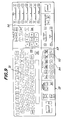
mark selection unit 19. Themark selection unit 19 comprises a group ofinput keys 51 for entering various kinds of patient data such as the sex and race of the patient, aswitch 52 for generating a group of organ marks, aswitch 53 for generating a group of posture marks, mark selection switches 54 for selecting organ and posture marks, switches 55 for moving and rotating the ultrasonic wave transmittingpoint indicating mark 23, and aswitch 56 for changing the function of theswitches 55 between the linear movement and the rotation. - Fig. 10 is a schematic view showing an example of the composite image displayed on the display screen of the
monitor 15. On the screen of themonitor 15 there are displayedultrasonic image 61, gray scale bar 62, andrange scale 63. On the monitor screen there are further provide amark display region 64 for displaying selectedposture mark 20 andorgan mark 21, and a markgroup display region 65 for displaying a group of marks. On theorgan mark 21 there is displayed the ultrasonic wave transmittingpoint indicating mark 23 in superimposition thereon. - At first, the
switch 53 on themark selection unit 19 is operated to display a group of posture marks on the markgroup display region 65 as depicted in Fig. 11. Then, a desired posture mark is selected by operating any one of the mark selection switches 54, and a selectedposture mark 20 is read out of themark memory 18 and is displayed in themark display region 64 of the display screen of the monitor. When theswitch 52 is operated, the group of organ marks 21 is displayed on the markgroup display region 65 as illustrated in Fig. 12. In this case, organ marks corresponding to the previously entered sex and race data of the patient are selectively read out of themark memory 18. Then, a desired one of the mark selection switches 54 is operated to select a desired organ mark and the thus selectedorgan mark 21 is read out of themark memory 18 and is displayed on themark display region 64 in the display screen. Next the ultrasonic wave transmittingpoint indicating mark 23 is displayed on theorgan mark 21 displayed in themark display region 64 by suitably operating the linear movement-rotation changing switch 56 as well as the movement-rotation switches 55. That is to say, at first an indication mark in the form of a bar is displayed on the screen. Then, theswitch 56 is operated to set theswitches 55 into the linear-movement mode and the indication mark is parallelly shifted by operating theswitches 55. After the indication mark is shifted into a desired position, theswitch 56 is operated to change the mode of theswitches 55 into the rotation mode, and the indication mark is rotated by operating theswitches 55. - In this manner, the composite image including the
ultrasonic image 61,posture mark 20,organ mark 21 and ultrasonic wave transmittingpoint indicating mark 23 as shown in Fig. 10 can be displayed on the display screen of themonitor 15. Therefore, one can understand what part of what organ of the patient is taken as the ultrasonic image, so that a very accurate diagnosis can be performed by monitoring the composite image. - In Fig. 13, which shows third ultrasonic diagnostic apparatus embodying the present invention, portions similar to those shown in Fig. 2 are denoted by the same reference numerals as used in Fig. 2. In the apparatus of Fig. 13, the
organ mark 21 is automatically, rather than manually, selected. To this end, there is provided a scopecode judging device 31 for automatically judging a kind of theultrasonic probe 13, and in theultrasonic probe 13 there is provided a scope code generating device. When the ultrasonic prove 13 is coupled with themain body 16, the scopecode judging device 31 detects a scope code generated by the scope code generating device provided in theultrasonic probe 13. The thus detected scope code is supplied to thecontroller 11. Then, thecontroller 11 operates to automatically select a desired organ mark from the group of organ marks stored in thememory 18. The remaining construction of the present embodiment is same as that of the first embodiment illustrated in Fig. 2. - In the apparatus of Fig. 13, the organ mark is automatically selected by coupling the
ultrasonic probe 13 to themain body 16, so that the operation of the operator becomes simple. Further a possible error in the manual selection of the organ mark can be effectively prevented. - In fourth ultrasonic diagnostic apparatus embodying the present invention which is shown in Fig. 14, the ultrasonic wave transmitting
point indicating mark 23 is automatically generated by detecting the movement of the angle knob (not shown) provided in theultrasonic probe 13 for moving a distal end of the ultrasonic probe and a length of a portion of an insertion section of theultrasonic probe 13 which has been inserted into the cavity of the patient. To this end, theultrasonic probe 13 is constructed to generate up/down and right/left signals in relation to the operation of the angle knob and the length of the insertion section of the probe which has been inserted into the cavity, and in themain body 16 there is arranged a distalend position sensor 41 for detecting the movement of the angle knob of theultrasonic probe 13 and a point within the cavity up to which the distal end of the probe has been inserted. An output signal of the distalend position sensor 41 is supplied to thecontroller 11, and the controller controls the ultrasonic wave transmitting point indicatingmark generating device 22 to produce automatically an ultrasonic wave transmitting point indicating mark signal related to the operation of the angle knob of the ultrasonic probe and the length of the insertion section of the probe which has been inserted into the cavity. Also in the present embodiment, the manual operation of the operator can be saved and any possible error due to the manual operation can be avoided. - In the embodiment illustrated in Fig. 5, a plurality of marks of the same organ belonging to different races are previously stored in the
memory 18. Alternatively, however, if appropriate only organ marks which are specific to a single race in whose territory the ultrasonic diagnosing apparatus is to be used need be stored in the mark memory. - Figs. 15 to 20 show some examples of the composite image displayed on the display screen of the monitor. It should be noted that in these composite images the posture mark is not included.
- In Fig. 15, there is displayed an ultrasonic image of a colon having a
polyp 106 and at the same time there is displayed acolon mark 103 at a left lower region of the monitor screen. Fig. 16 is an enlarged view of thecolon mark 103 shown in Fig. 15. In superimposition of the colon mark there is also shown an ultrasonic wave transmittingpoint indicating mark 104 indicating a point from and a direction in which the ultrasonic wave is transmitted. - In Fig. 17, the ultrasonic image is displayed as a three-dimensional image by processing the echo signal while a distal end of the ultrasonic probe of the radial scanning type is linearly moved within a cavity. In a left lower portion of the display screen, there is also displayed an
organ mark 103. Fig. 18 is an enlarged view of theorgan mark 103 shown in Fig. 17. Theorgan mark 103 is also displayed as a simple three-dimensional image and a point of the organ under inspection is displayed by anarea mark 105. - Fig. 19 is a three-dimensional ultrasonic image which is obtained by rotating the three-dimensional ultrasonic image illustrated in Fig. 17. In a right lower portion of the display screen there is displayed a three-
dimensional organ mark 103. As shown in Fig. 20 the organ mark is also rotated in relation to the rotation of the ultrasonic three-dimensional ultrasonic image. - In Fig. 16 the position and direction of the ultrasonic wave transmitting
point indicating mark 104 may be set by operating a suitable operating member such as a track ball. Further the rotation of the ultrasonic image shown in Figs. 17 and 19 may be performed by operating the track ball. In this case, theorgan mark 103 is also rotated accordingly, so that the position and size of the polyp can be judged in an easy and accurate manner. Further the relative position of the polyp with respect to surrounding organs and blood vessels can be understood at a glance, and thus the diagnosis can be performed more accurately and a very large amount of useful data for diagnosis and surgical operations can be obtained. - As explained above in detail, since in ultrasonic diagnostic apparatus embodying the present invention, the composite image displayed includes a posture mark, accurate diagnosis is facilitated.
Claims (10)
- Ultrasonic diagnostic apparatus, of the type having an ultrasonic probe (13) insertable into a body cavity of a patient under examination, for generating, when the apparatus is in use, an ultrasonic image of a selected part of that body cavity into which the probe (13) has been inserted; characterised by indicating means (17, 18, 19) for providing, in association with an ultrasonic image generated by the apparatus, an indication (20) of the posture held by the patient when the image was generated.
- Apparatus as claimed in claim 1, wherein the said indicating means (17, 18, 19) are operable to provide an indication (21), in association with an ultrasonic image generated by the apparatus, of which body cavity is shown in said image.
- Apparatus as claimed in claim 1 or 2, wherein the said indicating means (17, 18, 19, 22) are operable to provide an indication (23), in association with an ultrasonic image generated by the apparatus, of the point from, and direction in, which the image was taken.
- An ultrasonic diagnostic apparatus comprising: an ultrasonic probe which is insertable into a cavity of a patient for transmitting an ultrasonic wave toward a cavity wall and receiving an ultrasonic wave reflected by the cavity wall to generate an echo signal;
an image signal processing circuit connected to said ultrasonic probe for receiving said echo signal and processing the echo signal to produce an ultrasonic image signal;
a memory means for storing a plurality of posture marks which represent postures of the patient on a bed and a plurality of organ marks which represent organs of the patient;
a selecting means for selecting a desired posture mark among said plurality of posture marks and a desired organ mark among said plurality of organ marks to produce a posture mark signal and an organ mark signal;
an image processing means for mixing said posture mark signal representing said desire posture mark and said organ mark signal representing said desired organ mark with the ultrasonic image signal generated by said image signal processing means to produce a composite image signal; and
a displaying means for receiving said composite image signal to display a composite image of ultrasonic image, posture mark and organ mark. - An apparatus according to claim 4, wherein said mark selecting means comprises a means for displaying a plurality of organ mark signals stored in said memory means, a means for selecting one of the thus displayed organ marks, a means for displaying said plurality of posture marks, and a means for selecting one of the thus displayed posture marks.
- An apparatus according to claim 5, wherein said memory means is constructed to store a plurality of organ marks belonging to each of a plurality of organs depending upon the sex and race.
- An apparatus according to claim 4, 5 or 6, further comprising a means for displaying an ultrasonic wave transmitting point indicating mark for indicating a point at which the ultrasonic wave is transmitted in superimposition with the selected and displayed organ mark.
- An apparatus according to claim 7, wherein said means for displaying the ultrasonic wave transmitting point indicating mark comprises a means for displaying a point indication mark, means for parallelly moving the point indication mark and a means for rotating the point indication mark.
- An apparatus according to claim 7, wherein said means for displaying the ultrasonic wave transmitting point indicating mark comprises a distal end position sensor for detecting an operation of an angle knob for moving a distal end of the ultrasonic probe as well as a length of the ultrasonic probe which is inserted into the cavity of the patient and a means for responding to an output signal of said distal end position sensor to generate an ultrasonic wave transmitting point indicating mark signal.
- An apparatus according to claim 4, wherein said ultrasonic probe is provided to be detachably coupled with a main body of the apparatus and has an organ indicating means for denoting an organ specific to a relevant ultrasonic probe, and said organ mark selecting means comprises a means for detecting said organ denoted by said organ indicating means and a means for automatically selecting an organ mark on the basis of an output signal of said means for detecting the organ denoted by said organ indicating means.
Applications Claiming Priority (4)
| Application Number | Priority Date | Filing Date | Title |
|---|---|---|---|
| JP5557591 | 1991-02-28 | ||
| JP55575/91 | 1991-02-28 | ||
| JP17643/92 | 1992-02-03 | ||
| JP1764392A JP3145164B2 (en) | 1991-02-28 | 1992-02-03 | Ultrasound diagnostic equipment |
Publications (3)
| Publication Number | Publication Date |
|---|---|
| EP0501819A2 true EP0501819A2 (en) | 1992-09-02 |
| EP0501819A3 EP0501819A3 (en) | 1993-04-21 |
| EP0501819B1 EP0501819B1 (en) | 1996-12-18 |
Family
ID=26354201
Family Applications (1)
| Application Number | Title | Priority Date | Filing Date |
|---|---|---|---|
| EP19920301716 Expired - Lifetime EP0501819B1 (en) | 1991-02-28 | 1992-02-28 | Ultrasonic diagnostic apparatus |
Country Status (4)
| Country | Link |
|---|---|
| US (1) | US5211167A (en) |
| EP (1) | EP0501819B1 (en) |
| JP (1) | JP3145164B2 (en) |
| DE (1) | DE69215927T2 (en) |
Cited By (4)
| Publication number | Priority date | Publication date | Assignee | Title |
|---|---|---|---|---|
| US5617858A (en) * | 1994-08-30 | 1997-04-08 | Vingmed Sound A/S | Apparatus for endoscopic or gastroscopic examination |
| WO2000019907A1 (en) * | 1998-10-06 | 2000-04-13 | Boston Scientific Limited | Control panel for intravascular ultrasonic imaging system |
| EP2446827A1 (en) * | 2010-11-02 | 2012-05-02 | Samsung Medison Co., Ltd. | Providing a body mark in an ultrasound system |
| CN105662466A (en) * | 2016-01-11 | 2016-06-15 | 深圳开立生物医疗科技股份有限公司 | Body position icon, adding method, control device and ultrasonic equipment of control device |
Families Citing this family (16)
| Publication number | Priority date | Publication date | Assignee | Title |
|---|---|---|---|---|
| US5398685A (en) * | 1992-01-10 | 1995-03-21 | Wilk; Peter J. | Endoscopic diagnostic system and associated method |
| US5315999A (en) * | 1993-04-21 | 1994-05-31 | Hewlett-Packard Company | Ultrasound imaging system having user preset modes |
| US5782766A (en) * | 1995-03-31 | 1998-07-21 | Siemens Medical Systems, Inc. | Method and apparatus for generating and displaying panoramic ultrasound images |
| JPH08280684A (en) * | 1995-04-18 | 1996-10-29 | Fujitsu Ltd | Ultrasonic diagnostic apparatus |
| US6122967A (en) * | 1998-06-18 | 2000-09-26 | The United States Of America As Represented By The United States Department Of Energy | Free motion scanning system |
| JP4533494B2 (en) * | 2000-02-18 | 2010-09-01 | 株式会社東芝 | Ultrasound diagnostic imaging equipment |
| US6991605B2 (en) * | 2002-12-18 | 2006-01-31 | Siemens Medical Solutions Usa, Inc. | Three-dimensional pictograms for use with medical images |
| CN1753644A (en) * | 2003-02-28 | 2006-03-29 | 松下电器产业株式会社 | Ultrasonographic display device |
| JP4167162B2 (en) * | 2003-10-14 | 2008-10-15 | アロカ株式会社 | Ultrasonic diagnostic equipment |
| JP4263579B2 (en) * | 2003-10-22 | 2009-05-13 | アロカ株式会社 | Ultrasonic diagnostic equipment |
| KR101182880B1 (en) * | 2009-01-28 | 2012-09-13 | 삼성메디슨 주식회사 | Ultrasound system and method for providing image indicator |
| CN102292015B (en) * | 2009-11-19 | 2014-12-17 | 奥林巴斯医疗株式会社 | Medical device system, capsule medical device system, and method for displaying posture items of body to be tested |
| EP2491865A1 (en) | 2011-02-24 | 2012-08-29 | Samsung Medison Co., Ltd. | Ultrasound system for providing image indicator |
| JP6012288B2 (en) * | 2012-06-27 | 2016-10-25 | 株式会社日立製作所 | Ultrasonic diagnostic equipment |
| KR102416511B1 (en) * | 2014-12-23 | 2022-07-05 | 삼성메디슨 주식회사 | Method and apparatus for generating a body marker |
| CN108013900B (en) * | 2017-11-30 | 2021-02-05 | 无锡祥生医疗科技股份有限公司 | Ultrasonic imaging marking method and system thereof |
Citations (3)
| Publication number | Priority date | Publication date | Assignee | Title |
|---|---|---|---|---|
| EP0083973A1 (en) * | 1982-01-07 | 1983-07-20 | Technicare Corporation | Ultrasound probe locator |
| EP0127157A2 (en) * | 1983-05-25 | 1984-12-05 | Aloka Co. Ltd. | Ultrasonic diagnostic apparatus |
| EP0157302A1 (en) * | 1984-03-24 | 1985-10-09 | Kabushiki Kaisha Toshiba | Ultrasonic imaging apparatus using scale control |
Family Cites Families (7)
| Publication number | Priority date | Publication date | Assignee | Title |
|---|---|---|---|---|
| US4062237A (en) * | 1976-05-07 | 1977-12-13 | Fox Martin D | Crossed beam ultrasonic flowmeter |
| JPS5883942A (en) * | 1981-11-12 | 1983-05-19 | 株式会社東芝 | Ultrasonic pulse doppler apparatus |
| JPH0665338B2 (en) * | 1983-05-31 | 1994-08-24 | 株式会社東芝 | Ultrasonic diagnostic equipment |
| JPS6072541A (en) * | 1983-09-29 | 1985-04-24 | 株式会社島津製作所 | Diagnostic region display method of ultrasonic diagnostic apparatus |
| US4671292A (en) * | 1985-04-30 | 1987-06-09 | Dymax Corporation | Concentric biopsy probe |
| JPS63317140A (en) * | 1987-06-19 | 1988-12-26 | Toshiba Corp | Ultrasonic diagnostic apparatus |
| DE3811872A1 (en) * | 1988-04-09 | 1989-10-26 | Wolf Gmbh Richard | DEVICE FOR LOCATING AND DESTROYING OBJECTS WITH ULTRASOUND |
-
1992
- 1992-02-03 JP JP1764392A patent/JP3145164B2/en not_active Expired - Fee Related
- 1992-02-21 US US07/838,920 patent/US5211167A/en not_active Expired - Lifetime
- 1992-02-28 EP EP19920301716 patent/EP0501819B1/en not_active Expired - Lifetime
- 1992-02-28 DE DE1992615927 patent/DE69215927T2/en not_active Expired - Fee Related
Patent Citations (3)
| Publication number | Priority date | Publication date | Assignee | Title |
|---|---|---|---|---|
| EP0083973A1 (en) * | 1982-01-07 | 1983-07-20 | Technicare Corporation | Ultrasound probe locator |
| EP0127157A2 (en) * | 1983-05-25 | 1984-12-05 | Aloka Co. Ltd. | Ultrasonic diagnostic apparatus |
| EP0157302A1 (en) * | 1984-03-24 | 1985-10-09 | Kabushiki Kaisha Toshiba | Ultrasonic imaging apparatus using scale control |
Non-Patent Citations (1)
| Title |
|---|
| JP-59-222140 * |
Cited By (6)
| Publication number | Priority date | Publication date | Assignee | Title |
|---|---|---|---|---|
| US5617858A (en) * | 1994-08-30 | 1997-04-08 | Vingmed Sound A/S | Apparatus for endoscopic or gastroscopic examination |
| WO2000019907A1 (en) * | 1998-10-06 | 2000-04-13 | Boston Scientific Limited | Control panel for intravascular ultrasonic imaging system |
| US6358207B1 (en) | 1998-10-06 | 2002-03-19 | Scimed Life Systems, Inc. | Control panel for intravascular ultrasonic imaging system |
| US6361497B1 (en) | 1998-10-06 | 2002-03-26 | Scimed Life Systems, Inc. | Control panel for intravascular ultrasonic imaging system |
| EP2446827A1 (en) * | 2010-11-02 | 2012-05-02 | Samsung Medison Co., Ltd. | Providing a body mark in an ultrasound system |
| CN105662466A (en) * | 2016-01-11 | 2016-06-15 | 深圳开立生物医疗科技股份有限公司 | Body position icon, adding method, control device and ultrasonic equipment of control device |
Also Published As
| Publication number | Publication date |
|---|---|
| JP3145164B2 (en) | 2001-03-12 |
| DE69215927T2 (en) | 1997-05-15 |
| JPH05111488A (en) | 1993-05-07 |
| EP0501819B1 (en) | 1996-12-18 |
| EP0501819A3 (en) | 1993-04-21 |
| DE69215927D1 (en) | 1997-01-30 |
| US5211167A (en) | 1993-05-18 |
Similar Documents
| Publication | Publication Date | Title |
|---|---|---|
| EP0501819B1 (en) | Ultrasonic diagnostic apparatus | |
| US5617858A (en) | Apparatus for endoscopic or gastroscopic examination | |
| US5345938A (en) | Diagnostic apparatus for circulatory systems | |
| US5568812A (en) | Diagnostic ultrasound apparatus | |
| EP2042102B1 (en) | Ultrasonic diagnostic apparatus | |
| US5207225A (en) | Transesophageal ultrasonic scanhead | |
| US5551434A (en) | Ultrasonic imaging diagnosis apparatus | |
| JP3354619B2 (en) | Ultrasound diagnostic equipment | |
| EP1543776B1 (en) | Ultrasonograph | |
| KR100946826B1 (en) | System controller | |
| US6110114A (en) | Flexible beam sequencing for 3-dimensional ultrasound imaging | |
| KR100740378B1 (en) | Ultrasonic diagnostic apparatus | |
| US5660179A (en) | Ultrasonic diagnostic apparatus | |
| JP3325226B2 (en) | Ultrasound diagnostic equipment | |
| JP2005000390A (en) | Ultrasonograph | |
| JPH0665338B2 (en) | Ultrasonic diagnostic equipment | |
| JP2001299761A (en) | Ultrasonograph instrument and its control method | |
| JP4533494B2 (en) | Ultrasound diagnostic imaging equipment | |
| JP2002282250A (en) | Ultrasonographic device | |
| JPH08238209A (en) | Insertion depth detector | |
| JP2005288043A (en) | Medical image diagnosing apparatus | |
| JPH07184906A (en) | Ultrasonic diagnostic device | |
| JP7447692B2 (en) | Ultrasonic diagnostic device, method of controlling the ultrasonic diagnostic device, and control program for the ultrasonic diagnostic device | |
| JP2959161B2 (en) | Ultrasound diagnostic equipment | |
| JP2001327491A (en) | Ultrasonic diagnosing system |
Legal Events
| Date | Code | Title | Description |
|---|---|---|---|
| PUAI | Public reference made under article 153(3) epc to a published international application that has entered the european phase |
Free format text: ORIGINAL CODE: 0009012 |
|
| AK | Designated contracting states |
Kind code of ref document: A2 Designated state(s): DE FR GB IT NL |
|
| PUAL | Search report despatched |
Free format text: ORIGINAL CODE: 0009013 |
|
| AK | Designated contracting states |
Kind code of ref document: A3 Designated state(s): DE FR GB IT NL |
|
| 17P | Request for examination filed |
Effective date: 19930714 |
|
| 17Q | First examination report despatched |
Effective date: 19950518 |
|
| GRAG | Despatch of communication of intention to grant |
Free format text: ORIGINAL CODE: EPIDOS AGRA |
|
| GRAH | Despatch of communication of intention to grant a patent |
Free format text: ORIGINAL CODE: EPIDOS IGRA |
|
| GRAH | Despatch of communication of intention to grant a patent |
Free format text: ORIGINAL CODE: EPIDOS IGRA |
|
| GRAA | (expected) grant |
Free format text: ORIGINAL CODE: 0009210 |
|
| AK | Designated contracting states |
Kind code of ref document: B1 Designated state(s): DE FR GB IT NL |
|
| ET | Fr: translation filed | ||
| REF | Corresponds to: |
Ref document number: 69215927 Country of ref document: DE Date of ref document: 19970130 |
|
| ITF | It: translation for a ep patent filed |
Owner name: STUDIO TORTA SOCIETA' SEMPLICE |
|
| PLBE | No opposition filed within time limit |
Free format text: ORIGINAL CODE: 0009261 |
|
| STAA | Information on the status of an ep patent application or granted ep patent |
Free format text: STATUS: NO OPPOSITION FILED WITHIN TIME LIMIT |
|
| 26N | No opposition filed | ||
| REG | Reference to a national code |
Ref country code: GB Ref legal event code: IF02 |
|
| PGFP | Annual fee paid to national office [announced via postgrant information from national office to epo] |
Ref country code: NL Payment date: 20090215 Year of fee payment: 18 Ref country code: DE Payment date: 20090226 Year of fee payment: 18 |
|
| PGFP | Annual fee paid to national office [announced via postgrant information from national office to epo] |
Ref country code: GB Payment date: 20090225 Year of fee payment: 18 |
|
| PGFP | Annual fee paid to national office [announced via postgrant information from national office to epo] |
Ref country code: IT Payment date: 20090217 Year of fee payment: 18 |
|
| PGFP | Annual fee paid to national office [announced via postgrant information from national office to epo] |
Ref country code: FR Payment date: 20090213 Year of fee payment: 18 |
|
| REG | Reference to a national code |
Ref country code: NL Ref legal event code: V1 Effective date: 20100901 |
|
| GBPC | Gb: european patent ceased through non-payment of renewal fee |
Effective date: 20100228 |
|
| REG | Reference to a national code |
Ref country code: FR Ref legal event code: ST Effective date: 20101029 |
|
| PG25 | Lapsed in a contracting state [announced via postgrant information from national office to epo] |
Ref country code: NL Free format text: LAPSE BECAUSE OF NON-PAYMENT OF DUE FEES Effective date: 20100901 Ref country code: FR Free format text: LAPSE BECAUSE OF NON-PAYMENT OF DUE FEES Effective date: 20100301 |
|
| PG25 | Lapsed in a contracting state [announced via postgrant information from national office to epo] |
Ref country code: DE Free format text: LAPSE BECAUSE OF NON-PAYMENT OF DUE FEES Effective date: 20100901 |
|
| PG25 | Lapsed in a contracting state [announced via postgrant information from national office to epo] |
Ref country code: IT Free format text: LAPSE BECAUSE OF NON-PAYMENT OF DUE FEES Effective date: 20100228 Ref country code: GB Free format text: LAPSE BECAUSE OF NON-PAYMENT OF DUE FEES Effective date: 20100228 |