EP0503684A2 - Vector adaptive coding method for speech and audio - Google Patents
Vector adaptive coding method for speech and audio Download PDFInfo
- Publication number
- EP0503684A2 EP0503684A2 EP92108904A EP92108904A EP0503684A2 EP 0503684 A2 EP0503684 A2 EP 0503684A2 EP 92108904 A EP92108904 A EP 92108904A EP 92108904 A EP92108904 A EP 92108904A EP 0503684 A2 EP0503684 A2 EP 0503684A2
- Authority
- EP
- European Patent Office
- Prior art keywords
- vector
- speech
- pitch
- codebook
- vectors
- Prior art date
- Legal status (The legal status is an assumption and is not a legal conclusion. Google has not performed a legal analysis and makes no representation as to the accuracy of the status listed.)
- Granted
Links
Images


Classifications
-
- G—PHYSICS
- G10—MUSICAL INSTRUMENTS; ACOUSTICS
- G10L—SPEECH ANALYSIS OR SYNTHESIS; SPEECH RECOGNITION; SPEECH OR VOICE PROCESSING; SPEECH OR AUDIO CODING OR DECODING
- G10L19/00—Speech or audio signals analysis-synthesis techniques for redundancy reduction, e.g. in vocoders; Coding or decoding of speech or audio signals, using source filter models or psychoacoustic analysis
- G10L19/04—Speech or audio signals analysis-synthesis techniques for redundancy reduction, e.g. in vocoders; Coding or decoding of speech or audio signals, using source filter models or psychoacoustic analysis using predictive techniques
- G10L19/08—Determination or coding of the excitation function; Determination or coding of the long-term prediction parameters
- G10L19/083—Determination or coding of the excitation function; Determination or coding of the long-term prediction parameters the excitation function being an excitation gain
-
- G—PHYSICS
- G10—MUSICAL INSTRUMENTS; ACOUSTICS
- G10L—SPEECH ANALYSIS OR SYNTHESIS; SPEECH RECOGNITION; SPEECH OR VOICE PROCESSING; SPEECH OR AUDIO CODING OR DECODING
- G10L19/00—Speech or audio signals analysis-synthesis techniques for redundancy reduction, e.g. in vocoders; Coding or decoding of speech or audio signals, using source filter models or psychoacoustic analysis
- G10L19/04—Speech or audio signals analysis-synthesis techniques for redundancy reduction, e.g. in vocoders; Coding or decoding of speech or audio signals, using source filter models or psychoacoustic analysis using predictive techniques
- G10L19/06—Determination or coding of the spectral characteristics, e.g. of the short-term prediction coefficients
-
- G—PHYSICS
- G10—MUSICAL INSTRUMENTS; ACOUSTICS
- G10L—SPEECH ANALYSIS OR SYNTHESIS; SPEECH RECOGNITION; SPEECH OR VOICE PROCESSING; SPEECH OR AUDIO CODING OR DECODING
- G10L19/00—Speech or audio signals analysis-synthesis techniques for redundancy reduction, e.g. in vocoders; Coding or decoding of speech or audio signals, using source filter models or psychoacoustic analysis
- G10L19/04—Speech or audio signals analysis-synthesis techniques for redundancy reduction, e.g. in vocoders; Coding or decoding of speech or audio signals, using source filter models or psychoacoustic analysis using predictive techniques
- G10L19/26—Pre-filtering or post-filtering
-
- G—PHYSICS
- G10—MUSICAL INSTRUMENTS; ACOUSTICS
- G10L—SPEECH ANALYSIS OR SYNTHESIS; SPEECH RECOGNITION; SPEECH OR VOICE PROCESSING; SPEECH OR AUDIO CODING OR DECODING
- G10L19/00—Speech or audio signals analysis-synthesis techniques for redundancy reduction, e.g. in vocoders; Coding or decoding of speech or audio signals, using source filter models or psychoacoustic analysis
- G10L2019/0001—Codebooks
- G10L2019/0011—Long term prediction filters, i.e. pitch estimation
-
- G—PHYSICS
- G10—MUSICAL INSTRUMENTS; ACOUSTICS
- G10L—SPEECH ANALYSIS OR SYNTHESIS; SPEECH RECOGNITION; SPEECH OR VOICE PROCESSING; SPEECH OR AUDIO CODING OR DECODING
- G10L19/00—Speech or audio signals analysis-synthesis techniques for redundancy reduction, e.g. in vocoders; Coding or decoding of speech or audio signals, using source filter models or psychoacoustic analysis
- G10L2019/0001—Codebooks
- G10L2019/0013—Codebook search algorithms
- G10L2019/0014—Selection criteria for distances
Definitions
- This invention relates a real-time coder for compression of digitally encoded speech or audio signals for transmission or storage, and more particularly to a real-time vector adaptive predictive coding system.
- VQ Vector quantization
- VQ Vector quantization
- Adaptive Predictive Coding developed by Atal and Schroeder [B.S. Atal and M.R. Schroeder, "Adaptive Predictive Coding of Speech Signals,” Bell Syst. Tech. J., Vol. 49, pp. 1973-1986, October 1970; B.S. Atal and M.R. Schroeder, "Predictive Coding of Speech Signals and Subjective Error Criteria,” IEEE Trans. Acoust., Speech, Signal Proc., Vol. ASSP-27, No. 3, June 1979; and B.S. Atal, "Predictive Coding of Speech at Low Bit Rates," IEEE Trans.
- APC Adaptive Predictive Coding
- VQ and APC Vector Adaptive Predictive Coder
- APC The basic idea of APC is to first remove the redundancy in speech waveforms using adaptive linear predictors, and then quantize the prediction residual using a scalar quantizer.
- VAPC the scalar quantizer in APC is replaced by a vector quantizer VQ.
- VQ vector quantizer
- VAPC vector adaptive predictive coder
- VAPC gives very good speech quality at 9.6 kb/s, achieving 18 dB of signal-to-noise ratio (SNR) and 16 dB of segmental SNR. At 4.8- kb/s, VAPC also achieves reasonably good speech quality, and the SNR and segmental SNR are about 13 dB and 11.5 dB, respectively.
- the computations required to achieve these results are only in the order of 2 to 4 million flops per second (one flop, a floating point operation, is defined as one multiplication, one addition, plus the associated indexing), well within the capability of today's advanced digital signal processor chips.
- VAPC may become a low-complexity alternative to CELP, which is known to have achieved excellent speech quality at an expected bit rate around 4.8 kb/s but is not presently capable of being implemented in real-time due to its astronomical complexity. It requires over 400 million flops per second to implement the coder. In terms of the CPU time of a supercomputer CRAY-1, CELP requires 125 seconds of CPU time to encode one second of speech. There is currently a great need for a real-time, high-quality speech coder operating at encoding rates ranging from 4.8 to 9.6 kb/s. In this range of encoding rates, the two coders mentioned above (APC and CELP) are either unable to achieve high quality or too complex to implement. In contrast, the present invention, which combines Vector Quantization (VQ) with the advantages of both APC and CELP, is able to achieve high-quality speech with sufficiently low complexity for real-time coding.
- VQ Vector Quantization
- An object of this invention is to provide adaptive post-filtering of a speech or audio signal that has been corrupted by noise resulting from a coding system or other sources of degradation so as to enhance the perceived quality of said speech or audio signal.
- an adaptive postfiltering method for enhancing digitally processed speech or audio signals comprising the steps of buffering said speech or audio signals into frames of vectors, each vector having K successive samples, performing analysis of said speech signals in predetermined blocks to compute linear-predictive coefficient LPC predictor, pitch and pitch predictor parameters, and filtering each vector with long-delay and short-delay filtering in cascade, said long-delay filtering being controlled by pitch and pitch predictor parameters and said short-delay filtering being controlled by said LPC predictor parameters.
- the preferred embodiment provides postfiltering for use with a system which approximates each vector of K speech samples by using each of M fixed vectors stored in a VQ codebook to excite a time-varying synthesis filter and picking the best synthesized vector that minimizes a perceptually meaningful distortion measure.
- the original sampled speech is first buffered and partitioned into vectors and frames of vectors, where each frame is partitioned into N vectors, each vector having K speech samples.
- Predictive analysis of pitch-filtering parameters (P) linear-predictive coefficient filtering parameters (LPC), perceptual weighting filter parameters (W) and residual gain scaling factor (G) for each of successive frames of speech is then performed.
- the parameters determined in the analyses are quantized and reset every frame for processing each input vector s n in the frame, except the perceptual weighting parameter.
- a perceptual weighting filter responsive to the parameters W is used to help select the VQ vector that minimizes the perceptual distortion between the coded speech and the original speech.
- the perceptual weighting filter parameters are also reset every frame.
- M zero-state response vectors are computed and stored in a zero-state response codebook.
- These M zero-state response vectors are obtained by setting to zero the memory of an LPC synthesis filter and a perceptual weighting filter in cascade after a scaling unit controlled by the factor G, and controlling the respective filters with the quantized LPC filter parameters and the unquantized perceptual weighting filter parameters, and exciting the cascaded filters using one predetermined and fixed codebook vector at a time.
- the output vector of the cascaded filters for each VQ codebook vector is then stored in the corresponding address, i.e., is assigned the same index of a temporary zero-state response codebook as of the VQ codebook.
- a pitch prediction ⁇ n of the vector is determined by processing the last vector encoded as an index code through a scaling unit, LPC synthesis filter and pitch predictor filter controlled by the parameters QG, QLPC, QP and QPP for the frame.
- the zero-input response of the cascaded filters is first set in a filter.
- the pitch-predicted vector ⁇ n is subtracted from the input signal vector s n , and a difference vector d n is passed through the perceptual weighting filter to produce a filtered difference vector f n
- the zero-input response vector in the aforesaid filter is subtracted from the perceptual weight filtered difference vector f n
- the resulting vector v n is compared with each of the M stored zero-state response vectors in search of the one having a minimum difference ⁇ or distortion.
- the index (address) of the zero-state response vector that produces the smallest distortion i.e., that is closest to v n , identifies the best vector in the permanent codebook. Its index (address) is transmitted as the compressed code for the vector, and used by a receiver which has an identical VQ codebook as the transmitter to find the best-match vector. In the transmitter, that best-match vector is used at the time of transmission of its index to excite the LPC synthesis filter and pitch prediction filter to generate an estimate ⁇ n of the next speech vector. The best-match vector is also used to excite the zero-input response filter to set it for the next speech vector s n as described above.
- the indices of the best-match vector for a frame of vectors are combined in a multiplexer with the frame analysis information hereinafter referred to as "side information," comprised of the indices of parameters which control pitch, pitch predictor and LPC predictor filtering and the gain used in the coding process, in order that it may be used by the receiver in decoding the vector indices of a frame into vectors using a codebook identical to the permanent codebook at the transmitter.
- side information comprised of the indices of parameters which control pitch, pitch predictor and LPC predictor filtering and the gain used in the coding process, in order that it may be used by the receiver in decoding the vector indices of a frame into vectors using a codebook identical to the permanent codebook at the transmitter.
- This side information is preferably transmitted through the multiplexer first, once for each frame of VQ indices that follow, but it would be possible to first transmit a frame of vector indices, and then transmit the side information since the frames of vector indices will require some buffering in either case; the difference is only in some initial delay at the beginning of speech or audio frames transmitted in succession.
- the resulting stream of multiplexed indices are transmitted over a communication channel to a decoder, or stored for later decoding.
- the bit stream is first demultiplexed to separate the side information from the indices that follow.
- Each index is used at the receiver to extract the corresponding vector from the duplicate codebook.
- the extracted vector is first scaled by the gain parameter, using a table to convert the gain index to the appropriate scaling factor, and then used to excite cascaded LPC synthesis and pitch synthesis filters controlled by the same side information used in selecting the best-match index utilizing the zero-state response codebook in the transmitter.
- the output of the pitch synthesis filter is the coded speech, which is perceptually close to the original speech. All of the side information, except the gain information, is used in an adaptive postfilter to enhance the quality of the speech synthesized. This postfiltering technique may be used to enhance any voice or audio signal. All that would be required is an analysis section to produce the parameters used to make the postfilter adaptive.
- FIG. 1a is a block diagram of a Vector Adaptive Predictive Coding (VAPC) processor embodying the present invention
- FIG. 1b is a block diagram of a receiver for the encoded speech transmitted by the system of FIG. 1a.
- VAPC Vector Adaptive Predictive Coding
- FIG. 2 is a schematic diagram that illustrates the adaptive computation of vectors for a zero-state response codebook in the system of FIG. 1a.
- FIG. 3 is a block diagram of an analysis processor in the system of FIG. 1a.
- FIG. 4 is a block diagram of an adaptive post filter of FIG. 1b.
- FIG. 5 illustrates the LPC spectrum and the corresponding frequency response of an all-pole post-filter 1/[1 ⁇ -P(z/ ⁇ )] for different values of ⁇ .
- the offset between adjacent plots is 20 dB.
- FIG. 6 illustrates the frequency responses of the postfilter [1- ⁇ z ⁇ 1][1-P ⁇ (z/ ⁇ )]/[1-P ⁇ (z/ ⁇ )] corresponding to the LPC spectrum shown in FIG. 5.
- the offset between the two plots is 20 dB.
- the preferred mode of implementation contemplates using programmable digital signal processing chips, such as one or two AT&T DSP32 chips, and auxiliary chips for the necessary memory and controllers for such functions as input sampling, buffering and multiplexing. Since the system is digital, it is synchronized throughout with the samples. For simplicity of illustration and explanation, the synchronizing logic is not shown in the drawings. Also for simplification, at each point where a signal vector is subtracted from another, the subtraction function is symbolically indicated by an adder represented by a plus sign within a circle. The vector being subtracted is on the input labeled with a minus sign. In practice, the two's complement of the subtrahend is formed and added to the minuend. However, although the preferred implementation contemplates programmable digital signal processors, it would be possible to design and fabricate special integrated circuits using VLSI techniques to implement the present invention as a special purpose, dedicated digital signal processor once the quantities needed would justify the initial cost of design.
- original speech samples, s n in digital form from sampling analog-to-digital converter 10 are received by an analysis processor 11 which partitions them into vectors s n of K samples per vector, and into frames of N vectors per frame.
- the analysis processor stores the samples in a dual buffer memory which has the capacity for storing more than one frame of vectors, for example two frames of 8 vectors per frame, each vector consisting of 20 samples, so that the analysis processor may compute parameters used for coding the following frame.
- a new frame coming in is stored in the other buffer so that when processing of a frame has been completed, there is a new frame buffered and ready to be processed.
- the analysis processor determines the parameters of filters employed in the Vector Adaptive Predictive Coding technique that is the subject of this invention. These parameters are transmitted through a multiplexer 12 as side information just ahead of the frame of vector codes generated with the use of a vector quantized (VQ) permanent codebook 13 and a zero-state response (ZSR) codebook 14. The side information conditions the receiver to properly filter decoded vectors of the frame.
- the analysis processor 11 also computes other parameters used in the encoding process. The latter are represented in FIG.
- the multiplexer 12 preferably transmits the side information as soon as it is available, although it could follow the frame of encoded input vectors, and while that is being done, M zero-state response vectors are computed for the zero-state response (ZSR) codebook 14 in a manner illustrated in FIG. 2, which is to process each vector in the VQ codebook, 13 e.g., 128 vectors, through a gain scaling unit 17', an LPC synthesis filter 15', and perceptual weighting filters 18' corresponding to the gain scaling unit 17, the LPC synthesis filter 15, and perceptual weighting filter 18 in the transmitter (FIG. 1a).
- Ganged commutating switches S1 and S2 are shown to signify that each fixed VQ vector processed is stored in memory locations of the same index (address) in the ZSR codebook.
- the initial conditions of the cascaded filters 15' and 18' are set to zero. This simulates what the cascaded filters 15' and 18' will do with no previous vector present from its corresponding VQ codebook.
- the output of a zero-input response filter 19 in the transmitter (FIG. 1a) is held or stored, at each step of computing the VQ code index (to transmit for each vector of a frame), it is possible to simplify encoding the speech vectors by subtracting the zero-state response output from the vector f n .
- M 128, there are 128 different vectors permanently stored in the VQ codebook to use in coding the original speech vectors s n .
- every one of the 128 VQ vectors is read out in sequence, fed through the scaling unit 17', the LPC synthesis filter 15', and the perceptual weighting filter 18' without any history of previous vector inputs by resetting those filters at each step.
- the resulting filter output vector is then stored in a corresponding location in the zero-state response codebook. Later, while encoding input signal vectors s n by finding the best match between a vector v n and all of the zero state response vector codes, it is necessary to subtract from a vector f n derived from the perceptual weighting filter a value that corresponds to the effect of the previously selected VQ vector. That is done through the zero-input response filter 19.
- the index (address) of the best match is used as the compressed vector code transmitted for the vector s n .
- An address register 20a will store the index 38. It is that index that is then transmitted as a VQ index to the receiver shown in FIG. 1b.
- a demultiplexer 21 separates the side information which conditions the receiver with the same parameters as corresponding filters and scaling unit of the transmitter.
- the receiver uses a decoder 22 to translate the parameters indices to parameter values.
- the VQ index for each successive vector in the frame addresses a VQ codebook 23 which is identical to the fixed VQ codebook 13 of the transmitter.
- the LPC synthesis filter 24, pitch synthesis filter 25, and scaling unit 26 are conditioned by the same parameters which were used in computing the zero-state codebook values, and which were in turn used in the process of selecting the encoding index for each input vector.
- the zero-input response filter 19 computes from the VQ vector at the location of the index transmitted a value to be subtracted from the input vector f n to present a zero-input response to be used in the best-match search.
- the VQ codebook is used (accessed) in two different steps: first, to compute vector codes for the zero-state response codebook at the beginning of each frame, using the LPC synthesis and perceptual weighting filter parameters determined for the frame; and second, to excite the filters 15 and 16 through the scaling unit 17 while searching for the index of the best-match vector, during which the estimate ⁇ n thus produced is subtracted from the input vector s n .
- the difference d n is used in the best-match search.
- the corresponding predetermined and fixed vector from the VQ codebook is used to reset the zero input response filter 19 for the next vector of the frame.
- the function of the zero-input response filter 19 is thus to find the residual response of the gain scaling unit 17' and filters 15' and 18' to previously selected vectors from the VQ codebook.
- the selected vector is not transmitted; only its index is transmitted.
- At the receiver its index is used to read out the selected vector from a VQ codebook 23 identical to the VQ codebook 13 in the transmitter.
- the zero-input response filter 19 is the same filtering operation that is used to generate the ZSR codebook, namely the combination of a gain G, an LPC synthesis filter and a weighting filter, as shown in FIG. 2.
- the best-match vector is applied as an input to this filter (sample by sample, sequentially).
- An input switch s i is closed and an output switch s o is open during this time so that the first K output samples are ignored.
- K is the dimension of the vector and a typical value is 20.
- the filter input switch s i is opened and the output switch s o is closed.
- the next K samples of the vector f n the output of the perceptual weighting filter, begin to arrive and are subtracted from the samples of the vector f n .
- the difference so generated is a set of K samples forming the vector v n which is stored in a static register for use in the ZSR codebook search procedure.
- the vector v n is subtracted from each vector stored in the ZSR codebook, and the difference vector ⁇ is fed to the computer 20 together with the index (or stored in the same order), thereby to imply the index of the vector out of the ZSR codebook.
- the computer 20 determines which difference is the smallest, i.e., which is the best match between the vector v n and each vector stored temporarily (for one frame of input vectors s n ).
- the index of that best-match vector is stored in a register 20a. That index is transmitted as a vectorcode and used to address the VQ codebook to read the vector stored there into the scaling unit 17, as noted above. This search process is repeated for each vector in the ZSR codebook, each time using the same vector v n . Then the best vector is determined.
- the output of the VQ codebook 23, which precisely duplicates the VQ codebook 13 of the transmitter, is identical to the vector extracted from the best-match index applied as an address to the VQ codebook 13;
- the gain unit 26 is identical to the gain unit 17 in the transmitter, and filters 24 and 25 exactly duplicate the filters 15 and 16, respectively, except that at the receiver, the approximation n rather than the prediction ⁇ n is taken as the output of the pitch synthesis filter 25.
- the result after converting from digital to analog form, is synthesized speech that reproduces the original speech with very good quality.
- FIG. 4 illustrates the organization of the adaptive postfilter as a long-delay filter 31 and a short-delay filter 32. Both filters are adaptive in that the parameters used in them are those received as side information from the transmitter, except for the gain parameter, G.
- the basic idea of adaptive post-filtering is to attenuate the frequency components of the coded speech in spectral valley regions. At low bit rates, a considerable amount of perceived coding noise comes from spectral valley regions where there are no strong resonances to mask the noise.
- the postfilter attenuates the noise components in spectral valley regions to make the coding noise less perceivable.
- filtering operation inevitably introduces some distortion to the shape of the speech spectrum.
- our ears are not very sensitive to distortion in spectral valley regions; therefore, adaptive postfiltering only introduces very slight distortion in perceived speech, but it significantly reduces the perceived noise level.
- the adaptive postfilter will be described in greater detail after first describing in more detail the analysis of a frame of vectors to determine the side information.
- FIG. 3 it shows the organization of the initial analysis of block 11 in FIG. 1a.
- the input speech samples s n are first stored in a buffer 40 capable of storing, for example, more than one frame of 8 vectors, each vector having 20 samples.
- the parameters to be used, and their indices to be transmitted as side information are determined from that frame and at least a part of the previous frame in order to perform analysis with information from more than the frame of interest.
- the analysis is carried out as shown using a pitch detector 41, pitch quantizer 42 and a pitch predictor coefficient quantizer 43.
- pitch applies to any observed periodicity in the input signal, which may not necessarily correspond to the classical use of "pitch” corresponding to vibrations in the human vocal folds.
- the direct output of the speech is also used in the pitch predictor coefficient quantizer 43.
- the quantized pitch (QP) and quantized pitch predictor (QPP) are used to compute a pitch-prediction residual in block 44, and as control parameters for the pitch synthesis filter 16- used as a predictor in FIG. 1a. Only a pitch index and a pitch prediction index are included in the side information to minimize the number of bits transmitted. At the receiver, the decoder 22 will use each index to produce the corresponding control parameters for the pitch synthesis filter 25 .
- the pitch-prediction residual is stored in a buffer 45 for LPC analysis in block 46.
- the LPC predictor from the LPC analysis is quantized in block 47.
- the index of the quantized LPC predictor is transmitted as a third one of four pieces of side information, while the quantized LPC predictor is used as a parameter for control of the LPC synthesis filter 15, and in block 48 to compute the rms value of the LPC predictive residual.
- This value (unquantized residual gain) is then quantized in block 49 to provide gain control G in the scaling unit 17 of FIG. 1a.
- the index of the quantized residual gain is the fourth part of the side information transmitted.
- the analysis section provides LPC analysis in block 50 to produce an LPC predictor from which the set of parameters W for the perceptual weighting filter 18 (FIG. 1a) is computed in block 51.
- the adaptive postfilter 30 in FIG. 1b will now be described with reference to FIG. 4. It consists of a long-delay filter 31 and a short-delay filter 32 in cascade.
- the long-delay filter is derived from the decoded pitch-predictor information available at the receiver. It attenuates frequency components between pitch harmonic frequencies.
- the short-delay filter is derived from LPC predictor information, and it attenuates the frequency components between formant frequencies.
- Adaptive postfiltering has been used successfully in enhancing ADPCM-coded speech. See V. Ramamoorthy and J.S. Jayant, "Enhancement of ADPCM Speech by Adaptive Postfiltering," AT&T Bell Labs Tech. J., pp. 1465-1475, October 1984; and N.S. Jayant and V. Ramamoorthy, "Adaptive Postfiltering of 16 kb/s-ADPCM Speech," Proc. ICASSP, pp. 829-832, Tokyo, Japan, April 1986.
- the postfilter used by Ramamoorthy, et al., supra is derived from the two-pole six-zero ADPCM, synthesis filter by moving the poles and zeros radially toward the origin.
- the spectral tilt of the all-pole postfilter 1/[1-P ⁇ (z/ ⁇ )] can be easily reduced by adding zeros having the same phase angles as the poles but with smaller radii.
- the transfer function of the resulting pole-zero postfilter 32a has the form where ⁇ and ⁇ are coefficients empirically determined, with some tradeoff between spectral peaks being so sharp as to produce chirping and being so low as to not achieve any noise reduction.
- the frequency response of H(z) can be expressed as Therefore, in logarithmic scale, the frequency response of the pole-zero postfilter H(z) is simply the difference between the frequency responses of two all-pole postfilters.
- a first-order filter 32b which has a transfer function of [1- ⁇ z ⁇ 1], where ⁇ is typically 0.5. Such a filter provides a slightly highpassed spectral tilt and thus helps to reduce muffling.
- the short-delay postfilter 32 just described basically amplifies speech formants and attenuates inter-formant valleys. To obtain the ideal postfilter frequency response, we also have to amplify the pitch harmonics and attenuate the valleys between harmonics. Such a characteristic of frequency response can be achieved with a long-delay postfilter using the information in the pitch predictor.
- VAPC we use a three-tap pitch predictor; the pitch synthesis filter corresponding to such a pitch predictor is not guaranteed to be stable. Since the poles of such a synthesis filter may be outside the unit circle, moving the poles toward the origin may not have the same effect as in a stable LPC synthesis filter. Even if the three-tap pitch synthesis filter is stabilized, its frequency response may have an undesirable spectral tilt. Thus, it is not suitable to obtain the long-delay postfilter by scaling down the three tap weights of the pitch synthesis filter.
- the long-delay postfilter can be chosen as where p is determined by pitch analysis, and C g is an adaptive scaling factor.
- Uth is a threshold value (typically 0.6) determined empirically
- x can be either b2 or b1+b2+b3 depending on whether a one-tap or a three-tap pitch predictor is used. Since a quantized three-tap pitch predictor is preferred and therefore already available at the VAPC receiver, x is chosen as in VAPC postfiltering.
- x may be chosen as a single value b2 since a one-tap pitch predictor suffices.
- b2 when used alone indicates a value from a single-tap predictor, which in practice would be the same as a three-tap predictor when b1 and b3 are set to zero.
- AGC automatic gain control
- the purpose of AGC is to scale the enhanced speech such that it has roughly the same power as the unfiltered noisy speech. It is comprised of a gain (volume) estimator 33 operating on the speech input s(n), a gain (volume) estimator 34 operating on the postfiltered output r(n), and a circuit 35 to compute a scaling factor as the ratios of the two gains. The postfiltering output r(n) is then multiplied by this ratio in a multiplier 36 . AGC is thus achieved by estimating the power of the unfiltered and filtered speech separately and then using the ratio of the two values as the scaling factor.
- the complexity of the postfilter described in this section is only a small fraction of the overall complexity of the rest of the VAPC system, or any other coding system that may be used. In simulations, this postfilter achieves significant noise reduction with almost negligible distortion in speech. To test for possible distorting effects, the adaptive postfiltering operation was applied to clean, uncoded speech and it was found that the unfiltered original and its filtered version sound essentially the same, indicating that the distortion introduced by this postfilter is negligible.
- this novel postfiltering technique was developed for use with the VAPC system , its applications are not restricted to use with it. In fact, this technique can be used not only to enhance the quality of any noisy digital speech signal but also to enhance the decoded speech of other speech coders when provided with a buffer and analysis section for determining the parameters.
- VAPC Vector Adaptive Predictive Coder
- an inner-product approach is used for computing the norm (smallest distortion) which is more efficient than the conventional difference-square approach of computing the mean square error (MSE) distortion.
- MSE mean square error
- the complexity of the VAPC is only about 3 million multiply-adds/second and 6 k words of data memory.
- a single DSP32 chip was not sufficient for implementing the coder. Therefore, two DSP32 chips were used to implement the VAPC.
- a faster-DSP32 chip now available, which has an instruction cycle time of 160 ns rather than 250 ns, it is expected that the VAPC can be implemented using only one DSP32 chip.
Abstract
Description
- This invention relates a real-time coder for compression of digitally encoded speech or audio signals for transmission or storage, and more particularly to a real-time vector adaptive predictive coding system.
- In the past few years, most research in speech coding has focused on bit rates from 16 kb/s down to 150 bits/s. At the high end of this range, it is generally accepted that toll quality can be achieved at 16 kb/s by sophisticated waveform coders which are based on scalar quantization. N.S. Jayant and P. Noll, Digital Coding of Waveforms, Prentice-Hall Inc., Englewood Cliffs, N.J., 1984. At the other end, coders (such as linear-predictive coders) operating at 2400 bits/s or below only give synthetic-quality speech. For bit rates between these two extremes, particularly between 4.8 kb/s and 9.6 kb/s, neither type of coder can achieve high-quality speech. Part of the reason is that scalar quantization tends to break down at a bit rate of 1 bit/sample. Vector quantization (VQ), through its theoretical optimality and its capability of operating at a fraction of one bit per sample, offers the potential of achieving high-quality speech at 9.6 kb/s or even at 4.8 kb/s. J. Makhoul, S. Roucos, and H. Gish, "Vector Quantization in Speech Coding," Proc. IEEE, Vol. 73, No. 11, November 1985.
- Vector quantization (VQ) can achieve a performance arbitrarily close to the ultimate rate-distortion bound if the vector dimension is large enough. T. Berger, Rate Distortion Theory, Prentice-Hall Inc., Englewood Cliffs,N.J., 1971. However, only small vector dimensions can be used in practical systems due to complexity considerations, and unfortunately, direct waveform VQ using small dimensions does not give adequate performance. One possible way to improve the performance is to combine VQ with other data compression techniques which have been used successfully in scalar coding schemes.
- In speech coding below 16 kb/s, one of the most successful scalar coding schemes is Adaptive Predictive Coding (APC) developed by Atal and Schroeder [B.S. Atal and M.R. Schroeder, "Adaptive Predictive Coding of Speech Signals," Bell Syst. Tech. J., Vol. 49, pp. 1973-1986, October 1970; B.S. Atal and M.R. Schroeder, "Predictive Coding of Speech Signals and Subjective Error Criteria," IEEE Trans. Acoust., Speech, Signal Proc., Vol. ASSP-27, No. 3, June 1979; and B.S. Atal, "Predictive Coding of Speech at Low Bit Rates," IEEE Trans. Comm., Vol. COM-30, No. 4, April 1982]. It is the combined power of VQ and APC that led to the development of the present invention, a Vector Adaptive Predictive Coder (VAPC). Such a combination of VQ and APC will provide high-quality speech at bit rates between 4.8 and 9.6 kb/s, thus bridging the gap between scalar coders and VQ coders.
- The basic idea of APC is to first remove the redundancy in speech waveforms using adaptive linear predictors, and then quantize the prediction residual using a scalar quantizer. In VAPC, the scalar quantizer in APC is replaced by a vector quantizer VQ. The motivation for using VQ is two-fold. First, although linear dependency between adjacent speech samples is essentially removed by linear prediction, adjacent prediction residual samples may still have nonlinear dependency which can be exploited by VQ. Secondly, VQ can operate at rates below one bit per sample. This is not achievable by scalar quantization, but it is essential for speech coding at low bit rates.
- The vector adaptive predictive coder (VAPC) has evolved from APC and the vector predictive coder introduced by V. Cuperman and A. Gersho, "Vector Predictive Coding of Speech at 16 kb/s," IEEE Trans. Comm., Vol. COM-33, pp. 685-696, July 1985. VAPC contains some features that are somewhat similar to the Code-Excited Linear Prediction (CELP) coder by M.R. Schroeder, B.S. Atal, "Code-Excited Linear Prediction (CELP): High-Quality Speech at Very Low Bit Rates," Proc. Int'l. Conf. Acoustics, Speech, Signal Proc., Tampa, March 1985, but with much less computational complexity.
- In computer simulations, VAPC gives very good speech quality at 9.6 kb/s, achieving 18 dB of signal-to-noise ratio (SNR) and 16 dB of segmental SNR. At 4.8- kb/s, VAPC also achieves reasonably good speech quality, and the SNR and segmental SNR are about 13 dB and 11.5 dB, respectively. The computations required to achieve these results are only in the order of 2 to 4 million flops per second (one flop, a floating point operation, is defined as one multiplication, one addition, plus the associated indexing), well within the capability of today's advanced digital signal processor chips. VAPC may become a low-complexity alternative to CELP, which is known to have achieved excellent speech quality at an expected bit rate around 4.8 kb/s but is not presently capable of being implemented in real-time due to its astronomical complexity. It requires over 400 million flops per second to implement the coder. In terms of the CPU time of a supercomputer CRAY-1, CELP requires 125 seconds of CPU time to encode one second of speech. There is currently a great need for a real-time, high-quality speech coder operating at encoding rates ranging from 4.8 to 9.6 kb/s. In this range of encoding rates, the two coders mentioned above (APC and CELP) are either unable to achieve high quality or too complex to implement. In contrast, the present invention, which combines Vector Quantization (VQ) with the advantages of both APC and CELP, is able to achieve high-quality speech with sufficiently low complexity for real-time coding.
- An object of this invention is to provide adaptive post-filtering of a speech or audio signal that has been corrupted by noise resulting from a coding system or other sources of degradation so as to enhance the perceived quality of said speech or audio signal.
- According to the invention there is provided an adaptive postfiltering method for enhancing digitally processed speech or audio signals comprising the steps of
buffering said speech or audio signals into frames of vectors, each vector having K successive samples,
performing analysis of said speech signals in predetermined blocks to compute linear-predictive coefficient LPC predictor, pitch and pitch predictor parameters, and
filtering each vector with long-delay and short-delay filtering in cascade, said long-delay filtering being controlled by pitch and pitch predictor parameters and said short-delay filtering being controlled by said LPC predictor parameters. - The preferred embodiment provides postfiltering for use with a system which approximates each vector of K speech samples by using each of M fixed vectors stored in a VQ codebook to excite a time-varying synthesis filter and picking the best synthesized vector that minimizes a perceptually meaningful distortion measure. The original sampled speech is first buffered and partitioned into vectors and frames of vectors, where each frame is partitioned into N vectors, each vector having K speech samples. Predictive analysis of pitch-filtering parameters (P) linear-predictive coefficient filtering parameters (LPC), perceptual weighting filter parameters (W) and residual gain scaling factor (G) for each of successive frames of speech is then performed. The parameters determined in the analyses are quantized and reset every frame for processing each input vector sn in the frame, except the perceptual weighting parameter. A perceptual weighting filter responsive to the parameters W is used to help select the VQ vector that minimizes the perceptual distortion between the coded speech and the original speech. Although not quantized, the perceptual weighting filter parameters are also reset every frame.
- After each frame is buffered and the above analysis is completed at the beginning of each frame, M zero-state response vectors are computed and stored in a zero-state response codebook. These M zero-state response vectors are obtained by setting to zero the memory of an LPC synthesis filter and a perceptual weighting filter in cascade after a scaling unit controlled by the factor G, and controlling the respective filters with the quantized LPC filter parameters and the unquantized perceptual weighting filter parameters, and exciting the cascaded filters using one predetermined and fixed codebook vector at a time. The output vector of the cascaded filters for each VQ codebook vector is then stored in the corresponding address, i.e., is assigned the same index of a temporary zero-state response codebook as of the VQ codebook. In encoding each input speech vector sn within a frame, a pitch prediction ŝn of the vector is determined by processing the last vector encoded as an index code through a scaling unit, LPC synthesis filter and pitch predictor filter controlled by the parameters QG, QLPC, QP and QPP for the frame. In addition, the zero-input response of the cascaded filters (the ringing from excitation of a previous vector) is first set in a filter. Once the pitch-predicted vector ŝn is subtracted from the input signal vector sn, and a difference vector dn is passed through the perceptual weighting filter to produce a filtered difference vector fn, the zero-input response vector in the aforesaid filter is subtracted from the perceptual weight filtered difference vector fn, and the resulting vector vn is compared with each of the M stored zero-state response vectors in search of the one having a minimum difference Δ or distortion.
- The index (address) of the zero-state response vector that produces the smallest distortion, i.e., that is closest to vn, identifies the best vector in the permanent codebook. Its index (address) is transmitted as the compressed code for the vector, and used by a receiver which has an identical VQ codebook as the transmitter to find the best-match vector. In the transmitter, that best-match vector is used at the time of transmission of its index to excite the LPC synthesis filter and pitch prediction filter to generate an estimate ŝn of the next speech vector. The best-match vector is also used to excite the zero-input response filter to set it for the next speech vector sn as described above. The indices of the best-match vector for a frame of vectors are combined in a multiplexer with the frame analysis information hereinafter referred to as "side information," comprised of the indices of parameters which control pitch, pitch predictor and LPC predictor filtering and the gain used in the coding process, in order that it may be used by the receiver in decoding the vector indices of a frame into vectors using a codebook identical to the permanent codebook at the transmitter. This side information is preferably transmitted through the multiplexer first, once for each frame of VQ indices that follow, but it would be possible to first transmit a frame of vector indices, and then transmit the side information since the frames of vector indices will require some buffering in either case; the difference is only in some initial delay at the beginning of speech or audio frames transmitted in succession. The resulting stream of multiplexed indices are transmitted over a communication channel to a decoder, or stored for later decoding.
- In the decoder, the bit stream is first demultiplexed to separate the side information from the indices that follow. Each index is used at the receiver to extract the corresponding vector from the duplicate codebook. The extracted vector is first scaled by the gain parameter, using a table to convert the gain index to the appropriate scaling factor, and then used to excite cascaded LPC synthesis and pitch synthesis filters controlled by the same side information used in selecting the best-match index utilizing the zero-state response codebook in the transmitter. The output of the pitch synthesis filter is the coded speech, which is perceptually close to the original speech. All of the side information, except the gain information, is used in an adaptive postfilter to enhance the quality of the speech synthesized. This postfiltering technique may be used to enhance any voice or audio signal. All that would be required is an analysis section to produce the parameters used to make the postfilter adaptive.
- Other modifications and variation to this invention may occur to those skilled in the art, such as variable-frame-rate coding, fast codebook searching, reversal of the order of pitch prediction and LPC prediction, and use of alternative perceptual weighting techniques. Consequently, the claims which define the present invention are intended to encompass such modifications and variations.
- Although the purpose of this invention is to encode for transmission and/or storage of analog speech or audio waveforms for subsequent reconstruction of the waveforms upon reproduction of the speech or audio program, reference is made hereinafter only to speech, but the invention described and claimed is applicable to audio waveforms or to sub-band filtered speech or audio waveforms.
- The present application is a divisional application from European Patent Application 88303038.9 filed on 6 April 1988.
- An example of the invention will now be described with reference to the accompanying drawings.
- FIG. 1a is a block diagram of a Vector Adaptive Predictive Coding (VAPC) processor embodying the present invention, and FIG. 1b is a block diagram of a receiver for the encoded speech transmitted by the system of FIG. 1a.
- FIG. 2 is a schematic diagram that illustrates the adaptive computation of vectors for a zero-state response codebook in the system of FIG. 1a.
- FIG. 3 is a block diagram of an analysis processor in the system of FIG. 1a.
- FIG. 4 is a block diagram of an adaptive post filter of FIG. 1b.
- FIG. 5 illustrates the LPC spectrum and the corresponding frequency response of an all-pole post-filter 1/[1̂-P(z/ α)] for different values of α. The offset between adjacent plots is 20 dB.
- FIG. 6 illustrates the frequency responses of the postfilter [1-µz⁻¹][1-P̂(z/β)]/[1-P̂(z/ α)] corresponding to the LPC spectrum shown in FIG. 5. In both plots, α=0.8 and β=0.5. The offset between the two plots is 20 dB.
- The preferred mode of implementation contemplates using programmable digital signal processing chips, such as one or two AT&T DSP32 chips, and auxiliary chips for the necessary memory and controllers for such functions as input sampling, buffering and multiplexing. Since the system is digital, it is synchronized throughout with the samples. For simplicity of illustration and explanation, the synchronizing logic is not shown in the drawings. Also for simplification, at each point where a signal vector is subtracted from another, the subtraction function is symbolically indicated by an adder represented by a plus sign within a circle. The vector being subtracted is on the input labeled with a minus sign. In practice, the two's complement of the subtrahend is formed and added to the minuend. However, although the preferred implementation contemplates programmable digital signal processors, it would be possible to design and fabricate special integrated circuits using VLSI techniques to implement the present invention as a special purpose, dedicated digital signal processor once the quantities needed would justify the initial cost of design.
- Referring to FIG. 1a, original speech samples, sn in digital form from sampling analog-to-
digital converter 10 are received by ananalysis processor 11 which partitions them into vectors sn of K samples per vector, and into frames of N vectors per frame. The analysis processor stores the samples in a dual buffer memory which has the capacity for storing more than one frame of vectors, for example two frames of 8 vectors per frame, each vector consisting of 20 samples, so that the analysis processor may compute parameters used for coding the following frame. As each frame is being processed out of one buffer, a new frame coming in is stored in the other buffer so that when processing of a frame has been completed, there is a new frame buffered and ready to be processed. - The analysis processor determines the parameters of filters employed in the Vector Adaptive Predictive Coding technique that is the subject of this invention. These parameters are transmitted through a
multiplexer 12 as side information just ahead of the frame of vector codes generated with the use of a vector quantized (VQ)permanent codebook 13 and a zero-state response (ZSR)codebook 14. The side information conditions the receiver to properly filter decoded vectors of the frame. Theanalysis processor 11 also computes other parameters used in the encoding process. The latter are represented in FIG. 1a by dashed lines, and consist of sets of parameters which are designated W for aperceptual weighting filter 18, a quantized LPC predictor QLPC for anLPC synthesis filter 15, and quantized pitch QP and pitch predictor QPP for apitch synthesis filter 16. Also computed by the analysis processor is a scaling factor G for control of ascaling unit 17. The four quantized parameters transmitted as side information are encoded using a quantizing table as the quantized pitch index, pitch predictor index, LPC predictor index and gain index. The manner in which the analysis processor computes all of these parameters will be described with reference to FIG. 3. - The
multiplexer 12 preferably transmits the side information as soon as it is available, although it could follow the frame of encoded input vectors, and while that is being done, M zero-state response vectors are computed for the zero-state response (ZSR) codebook 14 in a manner illustrated in FIG. 2, which is to process each vector in the VQ codebook, 13 e.g., 128 vectors, through a gain scaling unit 17', an LPC synthesis filter 15', and perceptual weighting filters 18' corresponding to thegain scaling unit 17, theLPC synthesis filter 15, andperceptual weighting filter 18 in the transmitter (FIG. 1a). Ganged commutating switches S₁ and S₂ are shown to signify that each fixed VQ vector processed is stored in memory locations of the same index (address) in the ZSR codebook. - At the beginning of each vector processing, the initial conditions of the cascaded filters 15' and 18' are set to zero. This simulates what the cascaded filters 15' and 18' will do with no previous vector present from its corresponding VQ codebook. Thus, if the output of a zero-
input response filter 19 in the transmitter (FIG. 1a) is held or stored,
at each step of computing the VQ code index (to transmit for each vector of a frame), it is possible to simplify encoding the speech vectors by subtracting the zero-state response output from the vector fn. In other words, assuming M=128, there are 128 different vectors permanently stored in the VQ codebook to use in coding the original speech vectors sn. Then every one of the 128 VQ vectors is read out in sequence, fed through the scaling unit 17', the LPC synthesis filter 15', and the perceptual weighting filter 18' without any history of previous vector inputs by resetting those filters at each step. The resulting filter output vector is then stored in a corresponding location in the zero-state response codebook. Later, while encoding input signal vectors sn by finding the best match between a vector vn and all of the zero state response vector codes, it is necessary to subtract from a vector fn derived from the perceptual weighting filter a value that corresponds to the effect of the previously selected VQ vector. That is done through the zero-input response filter 19. The index (address) of the best match is used as the compressed vector code transmitted for the vector sn. Of the 128 zero-state response vectors, there will be only one that provides the best match, i.e., least distortion. Assume it is in location 38 of the zero-state response codebook as determined by acomputer 20 labeled "compute norm." An address register 20a will store the index 38. It is that index that is then transmitted as a VQ index to the receiver shown in FIG. 1b. - In the receiver, a
demultiplexer 21 separates the side information which conditions the receiver with the same parameters as corresponding filters and scaling unit of the transmitter. The receiver uses adecoder 22 to translate the parameters indices to parameter values. The VQ index for each successive vector in the frame addresses aVQ codebook 23 which is identical to the fixedVQ codebook 13 of the transmitter. TheLPC synthesis filter 24,pitch synthesis filter 25, and scalingunit 26 are conditioned by the same parameters which were used in computing the zero-state codebook values, and which were in turn used in the process of selecting the encoding index for each input vector. At each step of finding and transmitting an encoding index, the zero-input response filter 19 computes from the VQ vector at the location of the index transmitted a value to be subtracted from the input vector fn to present a zero-input response to be used in the best-match search. - There are various procedures that may be used to determine the best match for an input vector sn. The simplest is to store the resulting distortion between each zero-state response vectorcode output and the vector vn with the index of that. Assuming there are 128 vectorcodes stored in the
codebook 14, there would then be 128 resulting distortions stored in abest address computer 20. Then, after all have been stored, a search is made in thecomputer 20 for the lowest distortion value. Its index is then transmitted to the receiver as an encoded vector via themultiplexer 12, and to the VQ codebook for reading the corresponding VQ vector to be used in the processing of the next input vector sn. - In summary, it should be noted that the VQ codebook is used (accessed) in two different steps: first, to compute vector codes for the zero-state response codebook at the beginning of each frame, using the LPC synthesis and perceptual weighting filter parameters determined for the frame; and second, to excite the
filters unit 17 while searching for the index of the best-match vector, during which the estimate ŝn thus produced is subtracted from the input vector sn. The difference dn is used in the best-match search. - As the best match for each input vector sn is found, the corresponding predetermined and fixed vector from the VQ codebook is used to reset the zero
input response filter 19 for the next vector of the frame. The function of the zero-input response filter 19 is thus to find the residual response of the gain scaling unit 17' and filters 15' and 18' to previously selected vectors from the VQ codebook. Thus, the selected vector is not transmitted; only its index is transmitted. At the receiver its index is used to read out the selected vector from aVQ codebook 23 identical to theVQ codebook 13 in the transmitter. - The zero-
input response filter 19 is the same filtering operation that is used to generate the ZSR codebook, namely the combination of a gain G, an LPC synthesis filter and a weighting filter, as shown in FIG. 2. Once a best codebook vector match is determined, the best-match vector is applied as an input to this filter (sample by sample, sequentially). An input switch si is closed and an output switch so is open during this time so that the first K output samples are ignored. (K is the dimension of the vector and a typical value is 20.) As soon as all K samples have been applied as input to the filter, the filter input switch si is opened and the output switch so is closed. The next K samples of the vector fn, the output of the perceptual weighting filter, begin to arrive and are subtracted from the samples of the vector fn. The difference so generated is a set of K samples forming the vector vn which is stored in a static register for use in the ZSR codebook search procedure. In the ZSR codebook search procedure, the vector vn is subtracted from each vector stored in the ZSR codebook, and the difference vector Δ is fed to thecomputer 20 together with the index (or stored in the same order), thereby to imply the index of the vector out of the ZSR codebook. Thecomputer 20 then determines which difference is the smallest, i.e., which is the best match between the vector vn and each vector stored temporarily (for one frame of input vectors sn). The index of that best-match vector is stored in a register 20a. That index is transmitted as a vectorcode and used to address the VQ codebook to read the vector stored there into the scalingunit 17, as noted above. This search process is repeated for each vector in the ZSR codebook, each time using the same vector vn. Then the best vector is determined. - Referring now to FIG. 1b; it should be noted that the output of the
VQ codebook 23, which precisely duplicates theVQ codebook 13 of the transmitter, is identical to the vector extracted from the best-match index applied as an address to theVQ codebook 13; thegain unit 26 is identical to thegain unit 17 in the transmitter, and filters 24 and 25 exactly duplicate thefilters n rather than the prediction ŝn is taken as the output of the
pitch synthesis filter 25. The result, after converting from digital to analog form, is synthesized speech that reproduces the original speech with very good quality. - It has been found that by applying an
adaptive postfilter 30 to the synthesized speech before converting it from digital to analog form, the perceived coding noise may be greatly reduced without introducing significant distortion in the filtered speech. FIG. 4 illustrates the organization of the adaptive postfilter as a long-delay filter 31 and a short-delay filter 32. Both filters are adaptive in that the parameters used in them are those received as side information from the transmitter, except for the gain parameter, G. The basic idea of adaptive post-filtering is to attenuate the frequency components of the coded speech in spectral valley regions. At low bit rates, a considerable amount of perceived coding noise comes from spectral valley regions where there are no strong resonances to mask the noise. The postfilter attenuates the noise components in spectral valley regions to make the coding noise less perceivable. However, such filtering operation inevitably introduces some distortion to the shape of the speech spectrum. Fortunately, our ears are not very sensitive to distortion in spectral valley regions; therefore, adaptive postfiltering only introduces very slight distortion in perceived speech, but it significantly reduces the perceived noise level. The adaptive postfilter will be described in greater detail after first describing in more detail the analysis of a frame of vectors to determine the side information. - Referring now to FIG. 3, it shows the organization of the initial analysis of
block 11 in FIG. 1a. The input speech samples sn are first stored in abuffer 40 capable of storing, for example, more than one frame of 8 vectors, each vector having 20 samples. - Once a frame of input vectors sn has been stored, the parameters to be used, and their indices to be transmitted as side information, are determined from that frame and at least a part of the previous frame in order to perform analysis with information from more than the frame of interest. The analysis is carried out as shown using a
pitch detector 41,pitch quantizer 42 and a pitchpredictor coefficient quantizer 43. What is referred to as "pitch" applies to any observed periodicity in the input signal, which may not necessarily correspond to the classical use of "pitch" corresponding to vibrations in the human vocal folds. The direct output of the speech is also used in the pitchpredictor coefficient quantizer 43. The quantized pitch (QP) and quantized pitch predictor (QPP) are used to compute a pitch-prediction residual inblock 44, and as control parameters for the pitch synthesis filter 16- used as a predictor in FIG. 1a. Only a pitch index and a pitch prediction index are included in the side information to minimize the number of bits transmitted. At the receiver, thedecoder 22 will use each index to produce the corresponding control parameters for thepitch synthesis filter 25. - The pitch-prediction residual is stored in a
buffer 45 for LPC analysis inblock 46. The LPC predictor from the LPC analysis is quantized inblock 47. The index of the quantized LPC predictor is transmitted as a third one of four pieces of side information, while the quantized LPC predictor is used as a parameter for control of theLPC synthesis filter 15, and inblock 48 to compute the rms value of the LPC predictive residual. This value (unquantized residual gain) is then quantized inblock 49 to provide gain control G in thescaling unit 17 of FIG. 1a. The index of the quantized residual gain is the fourth part of the side information transmitted. - In addition to the foregoing, the analysis section provides LPC analysis in
block 50 to produce an LPC predictor from which the set of parameters W for the perceptual weighting filter 18 (FIG. 1a) is computed inblock 51. - The
adaptive postfilter 30 in FIG. 1b will now be described with reference to FIG. 4. It consists of a long-delay filter 31 and a short-delay filter 32 in cascade. The long-delay filter is derived from the decoded pitch-predictor information available at the receiver. It attenuates frequency components between pitch harmonic frequencies. The short-delay filter is derived from LPC predictor information, and it attenuates the frequency components between formant frequencies. - The noise masking effect of human auditory perception, recognized by M.R. Schroeder, B.S. Atal, and J.L. Hall, "Optimizing Digital Speech Coders by Exploiting Masking Properties of the Human Ear," J. Acoust. Soc. Am., Vol. 66, No. 6, pp. 1647-1652, December 1979, is exploited in VAPC by using noise spectral shaping. However, in noise spectral shaping, lowering noise components at certain frequencies can only be achieved at the price of increased noise components at other frequencies. [B.S. Atal and M.R. Schroeder, "Predictive Coding of Speech Signals and Subjective Error Criteria," IEEE Trans. Acoust., Speech, and Signal Processing, Vol. ASSP-27, No. 3, pp. 247-254, June 1979] Therefore, at bit rates as low as 4800 bps, where the average noise level is quite high, it is very difficult, if not impossible, to force noise below the masking threshold at all frequencies. Since speech formants are much more important to perception than spectral valleys, the approach of the present invention is to preserve the formant information by keeping the noise in the formant regions as low as is practical during encoding. Of course, in this case, the noise components in spectral valleys may exceed the threshold; however, these noise components can be attenuated later by the
postfilter 30. In performing such postfiltering, the speech components in spectral valleys will also be attenuated. Fortunately, the limen, or "just noticeable difference," for the intensity of spectral valleys can be quite large [J.L. Flanagan, Speech Analysis, Synthesis, and Perception, Academic Press, New York, 1972]. Therefore, by attenuating the components in spectral valleys, the postfilter only introduces minimal distortion in the speech signal, but it achieves a substantial noise reduction. - Adaptive postfiltering has been used successfully in enhancing ADPCM-coded speech. See V. Ramamoorthy and J.S. Jayant, "Enhancement of ADPCM Speech by Adaptive Postfiltering," AT&T Bell Labs Tech. J., pp. 1465-1475, October 1984; and N.S. Jayant and V. Ramamoorthy, "Adaptive Postfiltering of 16 kb/s-ADPCM Speech," Proc. ICASSP, pp. 829-832, Tokyo, Japan, April 1986. The postfilter used by Ramamoorthy, et al., supra, is derived from the two-pole six-zero ADPCM, synthesis filter by moving the poles and zeros radially toward the origin. If this idea is extended directly to an all-pole LPC synthesis filter 1/[1-P̂(z)], the result is l/[1-P̂(z/α)] as the corresponding postfilter, where 0<α<1. Such an all-pole postfilter indeed reduces the perceived noise level; however, sufficient noise reduction can only be achieved with severe muffling in the filtered speech. This is due to the fact that the frequency response of this all-pole postfilter generally has a lowpass spectral tilt for voiced speech.
- The spectral tilt of the all-pole postfilter 1/[1-P̂(z/α)] can be easily reduced by adding zeros having the same phase angles as the poles but with smaller radii. The transfer function of the resulting pole-zero
postfilter 32a has the form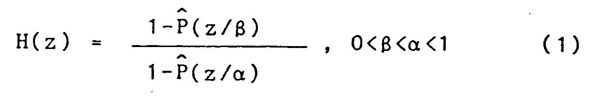
where α and β are coefficients empirically determined, with some tradeoff between spectral peaks being so sharp as to produce chirping and being so low as to not achieve any noise reduction. The frequency response of H(z) can be expressed as

Therefore, in logarithmic scale, the frequency response of the pole-zero postfilter H(z) is simply the difference between the frequency responses of two all-pole postfilters. - Typical values of α and β are 0.8 and 0.5, respectively. From FIG. 5, it is seen that the response for α=0.8 has both formant peaks and spectral tilt, while the response for α=0.5 has spectral tilt only. Thus, with α=0.8 and β=0.5 in
Equation 2, we can at least partially remove the spectral tilt by subtracting the response for α=0.5 from the response for α=0.8. The resulting frequency response of H(z) is shown in the upper plot of FIG. 6. - In informal listening tests, it has been found that the muffling effect was significantly reduced after the numerator term [1-P̂(z/β)] was included in the transfer function H(z). However, the filtered speech remained slightly muffled even with the spectral-tilt compensating term [1-P̂(z/β)]. To further reduce the muffling effect, a first-
order filter 32b was added which has a transfer function of [1-µz⁻¹], where µ is typically 0.5. Such a filter provides a slightly highpassed spectral tilt and thus helps to reduce muffling. This first-order filter is used in cascade with H(z), and a combined frequency response with µ=0.5 is shown in the lower plot of FIG. 6. - The short-
delay postfilter 32 just described basically amplifies speech formants and attenuates inter-formant valleys. To obtain the ideal postfilter frequency response, we also have to amplify the pitch harmonics and attenuate the valleys between harmonics. Such a characteristic of frequency response can be achieved with a long-delay postfilter using the information in the pitch predictor. - In VAPC, we use a three-tap pitch predictor; the pitch synthesis filter corresponding to such a pitch predictor is not guaranteed to be stable. Since the poles of such a synthesis filter may be outside the unit circle, moving the poles toward the origin may not have the same effect as in a stable LPC synthesis filter. Even if the three-tap pitch synthesis filter is stabilized, its frequency response may have an undesirable spectral tilt. Thus, it is not suitable to obtain the long-delay postfilter by scaling down the three tap weights of the pitch synthesis filter.
- With both poles and zeroes, the long-delay postfilter can be chosen as

where p is determined by pitch analysis, and Cg is an adaptive scaling factor. - Knowing the information provided by a single or three-tap pitch predictor as the value b₂ or the sum of b₁+b₂+b₃, the factors γ and λ are determined according to the following formulas:

where
where Uth is a threshold value (typically 0.6) determined empirically, and x can be either b₂ or b₁+b₂+b₃ depending on whether a one-tap or a three-tap pitch predictor is used. Since a quantized three-tap pitch predictor is preferred and therefore already available at the VAPC receiver, x is chosen as
in VAPC postfiltering. On the other hand, if the postfilter is used elsewhere to enhance noisy input speech, a separate pitch analysis is needed, and x may be chosen as a single value b₂ since a one-tap pitch predictor suffices. (The value b₂ when used alone indicates a value from a single-tap predictor, which in practice would be the same as a three-tap predictor when b₁ and b₃ are set to zero.) - The goal is to make the power of [y(n)] about the same as that of [s(n)]. An appropriate scaling factor is chosen as

- The first-
order filter 32b can also be made adaptive to better track the change in the spectral tilt of H(z). However, it has been found that even a fixed filter with µ=0.5 gives quite satisfactory results. A fixed value of µ may be determined empirically. - To avoid occasional large gain excursions, an automatic gain control (AGC) was added at the output of the adaptive postfilter. The purpose of AGC is to scale the enhanced speech such that it has roughly the same power as the unfiltered noisy speech. It is comprised of a gain (volume)
estimator 33 operating on the speech input s(n), a gain (volume)estimator 34 operating on the postfiltered output r(n), and acircuit 35 to compute a scaling factor as the ratios of the two gains. The postfiltering output r(n) is then multiplied by this ratio in amultiplier 36. AGC is thus achieved by estimating the power of the unfiltered and filtered speech separately and then using the ratio of the two values as the scaling factor. Let [s(n)] be the sequence of either unfiltered or filtered speech samples; then, the speech power σ²(n) is estimated by using

A suitable value of ξ is 0.99. - The complexity of the postfilter described in this section is only a small fraction of the overall complexity of the rest of the VAPC system, or any other coding system that may be used. In simulations, this postfilter achieves significant noise reduction with almost negligible distortion in speech. To test for possible distorting effects, the adaptive postfiltering operation was applied to clean, uncoded speech and it was found that the unfiltered original and its filtered version sound essentially the same, indicating that the distortion introduced by this postfilter is negligible.
- It should be noted that although this novel postfiltering technique was developed for use with the VAPC system , its applications are not restricted to use with it. In fact, this technique can be used not only to enhance the quality of any noisy digital speech signal but also to enhance the decoded speech of other speech coders when provided with a buffer and analysis section for determining the parameters.
- What has been disclosed is a real-time Vector Adaptive Predictive Coder (VAPC) for speech or audio which may be implemented with software using the commercially available AT&T DSP32 digital processing chip. In its newest version, this chip has a processing power of 6 million instructions per second (MIPS). To facilitate implementation for real-time speech coding, a simplified version of the 4800 bps VAPC is available. This simplified version has a much lower complexity, but gives nearly the same speech-quality as a full complexity version.
- In the real-time implementation, an inner-product approach is used for computing the norm (smallest distortion) which is more efficient than the conventional difference-square approach of computing the mean square error (MSE) distortion. Given a test vector v and M ZSR codebook vectors, zj, j=1,2, . . .,M, the j-th MSE distortion can be computed as

At the beginning of each frame, it is possible to compute and store 1/2∥ Zj ∥² . With the DSP32 processor and for the dimension and codebook size used, the difference-square approach of the codebook search requires about 2.5 MIPS to implement, while the inner-product approach only requires about 1.5 MIPS. - The complexity of the VAPC is only about 3 million multiply-adds/second and 6 k words of data memory. However, due to the overhead in implementation, a single DSP32 chip was not sufficient for implementing the coder. Therefore, two DSP32 chips were used to implement the VAPC. With a faster-DSP32 chip now available, which has an instruction cycle time of 160 ns rather than 250 ns, it is expected that the VAPC can be implemented using only one DSP32 chip.
Claims (6)
- An adaptive postfiltering method for enhancing digitally processed speech or audio signals comprising the steps of
buffering said speech or audio signals into frames of vectors, each vector having K successive samples,
performing analysis of said speech signals in predetermined blocks to compute linear-predictive coefficient LPC predictor, pitch and pitch predictor parameters, and
filtering each vector with long-delay and short-delay filtering in cascade, said long-delay filtering being controlled by pitch and pitch predictor parameters and said short-delay filtering being controlled by said LPC predictor parameters. - A method as claimed in claim 1 including automatic gain control of the adaptive postfiltered digitally encoded speech provided by computing a value σ₂(n) proportional to volume of postfiltered speech vectors and a value σ₁(n) proportional to volume of decoded speech vectors before postfiltering, and controlling the gain of the postfiltered speech vectors by a ratio of σ₁(n) to σ₂(n).
- A method as claimed in claim 3 wherein postfiltering is accomplished by using a transfer function for said long-delay postfilter of the form


where
- A method as claimed in claim 3 wherein postfiltering is accomplished by using a transfer function for said short-delay filter of the form

- A method as claimed in claim 4 wherein postfiltering further includes in cascade first-order filtering with a transfer function

- A method a claimed in any of claims 1 to 5 wherein said short-delay filtering is also controlled by said pitch and pitch predictor parameters.
Applications Claiming Priority (3)
| Application Number | Priority Date | Filing Date | Title |
|---|---|---|---|
| US35615 | 1987-04-06 | ||
| US07/035,615 US4969192A (en) | 1987-04-06 | 1987-04-06 | Vector adaptive predictive coder for speech and audio |
| EP88303038A EP0294020A3 (en) | 1987-04-06 | 1988-04-06 | Vector adaptive coding method for speech and audio |
Related Parent Applications (2)
| Application Number | Title | Priority Date | Filing Date |
|---|---|---|---|
| EP88303038.9 Division | 1988-04-06 | ||
| EP88303038A Division EP0294020A3 (en) | 1987-04-06 | 1988-04-06 | Vector adaptive coding method for speech and audio |
Publications (3)
| Publication Number | Publication Date |
|---|---|
| EP0503684A2 true EP0503684A2 (en) | 1992-09-16 |
| EP0503684A3 EP0503684A3 (en) | 1993-06-23 |
| EP0503684B1 EP0503684B1 (en) | 1998-07-01 |
Family
ID=21883771
Family Applications (2)
| Application Number | Title | Priority Date | Filing Date |
|---|---|---|---|
| EP88303038A Withdrawn EP0294020A3 (en) | 1987-04-06 | 1988-04-06 | Vector adaptive coding method for speech and audio |
| EP92108904A Expired - Lifetime EP0503684B1 (en) | 1987-04-06 | 1988-04-06 | Adaptive filtering method for speech and audio |
Family Applications Before (1)
| Application Number | Title | Priority Date | Filing Date |
|---|---|---|---|
| EP88303038A Withdrawn EP0294020A3 (en) | 1987-04-06 | 1988-04-06 | Vector adaptive coding method for speech and audio |
Country Status (6)
| Country | Link |
|---|---|
| US (1) | US4969192A (en) |
| EP (2) | EP0294020A3 (en) |
| JP (1) | JP2887286B2 (en) |
| AU (1) | AU1387388A (en) |
| CA (1) | CA1336454C (en) |
| DE (1) | DE3856211T2 (en) |
Cited By (10)
| Publication number | Priority date | Publication date | Assignee | Title |
|---|---|---|---|---|
| EP0743634A1 (en) * | 1995-05-17 | 1996-11-20 | France Telecom | Method of adapting the noise masking level in an analysis-by-synthesis speech coder employing a short-term perceptual weighting filter |
| EP0852376A2 (en) * | 1997-01-02 | 1998-07-08 | Texas Instruments Incorporated | Improved multimodal code-excited linear prediction (CELP) coder and method |
| US6058360A (en) * | 1996-10-30 | 2000-05-02 | Telefonaktiebolaget Lm Ericsson | Postfiltering audio signals especially speech signals |
| US6941263B2 (en) | 2001-06-29 | 2005-09-06 | Microsoft Corporation | Frequency domain postfiltering for quality enhancement of coded speech |
| US7177804B2 (en) | 2005-05-31 | 2007-02-13 | Microsoft Corporation | Sub-band voice codec with multi-stage codebooks and redundant coding |
| US7286982B2 (en) | 1999-09-22 | 2007-10-23 | Microsoft Corporation | LPC-harmonic vocoder with superframe structure |
| US7590531B2 (en) | 2005-05-31 | 2009-09-15 | Microsoft Corporation | Robust decoder |
| WO2009140896A1 (en) * | 2008-05-23 | 2009-11-26 | 华为技术有限公司 | A pitch post processing method, a filter and a pitch post processing system |
| US7668712B2 (en) | 2004-03-31 | 2010-02-23 | Microsoft Corporation | Audio encoding and decoding with intra frames and adaptive forward error correction |
| US7707034B2 (en) | 2005-05-31 | 2010-04-27 | Microsoft Corporation | Audio codec post-filter |
Families Citing this family (136)
| Publication number | Priority date | Publication date | Assignee | Title |
|---|---|---|---|---|
| US4899385A (en) * | 1987-06-26 | 1990-02-06 | American Telephone And Telegraph Company | Code excited linear predictive vocoder |
| CA2002015C (en) * | 1988-12-30 | 1994-12-27 | Joseph Lindley Ii Hall | Perceptual coding of audio signals |
| US5263119A (en) * | 1989-06-29 | 1993-11-16 | Fujitsu Limited | Gain-shape vector quantization method and apparatus |
| JPH0332228A (en) * | 1989-06-29 | 1991-02-12 | Fujitsu Ltd | Gain-shape vector quantization system |
| CA2021514C (en) * | 1989-09-01 | 1998-12-15 | Yair Shoham | Constrained-stochastic-excitation coding |
| IL95753A (en) * | 1989-10-17 | 1994-11-11 | Motorola Inc | Digital speech coder |
| EP0496829B1 (en) * | 1989-10-17 | 2000-12-06 | Motorola, Inc. | Lpc based speech synthesis with adaptive pitch prefilter |
| ES2131498T3 (en) * | 1989-10-17 | 1999-08-01 | Motorola Inc | DIGITAL VOICE DECODER THAT HAS A POSTFILTER WITH REDUCED SPECTRAL DISTORTION. |
| US5307441A (en) * | 1989-11-29 | 1994-04-26 | Comsat Corporation | Wear-toll quality 4.8 kbps speech codec |
| US5235669A (en) * | 1990-06-29 | 1993-08-10 | At&T Laboratories | Low-delay code-excited linear-predictive coding of wideband speech at 32 kbits/sec |
| JPH06138896A (en) * | 1991-05-31 | 1994-05-20 | Motorola Inc | Device and method for encoding speech frame |
| DE69233794D1 (en) * | 1991-06-11 | 2010-09-23 | Qualcomm Inc | Vocoder with variable bit rate |
| JP3076086B2 (en) * | 1991-06-28 | 2000-08-14 | シャープ株式会社 | Post filter for speech synthesizer |
| US5233660A (en) * | 1991-09-10 | 1993-08-03 | At&T Bell Laboratories | Method and apparatus for low-delay celp speech coding and decoding |
| US5339384A (en) * | 1992-02-18 | 1994-08-16 | At&T Bell Laboratories | Code-excited linear predictive coding with low delay for speech or audio signals |
| US5327520A (en) * | 1992-06-04 | 1994-07-05 | At&T Bell Laboratories | Method of use of voice message coder/decoder |
| FI95086C (en) * | 1992-11-26 | 1995-12-11 | Nokia Mobile Phones Ltd | Method for efficient coding of a speech signal |
| IT1272418B (en) * | 1993-04-29 | 1997-06-23 | Alcatel Italia | SYSTEM FOR THE TREATMENT OF SIGNALS AFFECTED BY TRANSMISSION ERRORS |
| FI96248C (en) * | 1993-05-06 | 1996-05-27 | Nokia Mobile Phones Ltd | Method for providing a synthetic filter for long-term interval and synthesis filter for speech coder |
| DE4315313C2 (en) * | 1993-05-07 | 2001-11-08 | Bosch Gmbh Robert | Vector coding method especially for speech signals |
| DE4315319C2 (en) * | 1993-05-07 | 2002-11-14 | Bosch Gmbh Robert | Method for processing data, in particular coded speech signal parameters |
| US5504834A (en) * | 1993-05-28 | 1996-04-02 | Motrola, Inc. | Pitch epoch synchronous linear predictive coding vocoder and method |
| US5479559A (en) * | 1993-05-28 | 1995-12-26 | Motorola, Inc. | Excitation synchronous time encoding vocoder and method |
| US5659659A (en) * | 1993-07-26 | 1997-08-19 | Alaris, Inc. | Speech compressor using trellis encoding and linear prediction |
| JPH07160297A (en) * | 1993-12-10 | 1995-06-23 | Nec Corp | Voice parameter encoding system |
| JP3024468B2 (en) * | 1993-12-10 | 2000-03-21 | 日本電気株式会社 | Voice decoding device |
| US5764698A (en) * | 1993-12-30 | 1998-06-09 | International Business Machines Corporation | Method and apparatus for efficient compression of high quality digital audio |
| FR2715755B1 (en) * | 1994-01-28 | 1996-04-12 | France Telecom | Speech recognition method and device. |
| CA2142391C (en) * | 1994-03-14 | 2001-05-29 | Juin-Hwey Chen | Computational complexity reduction during frame erasure or packet loss |
| JP3321976B2 (en) * | 1994-04-01 | 2002-09-09 | 富士通株式会社 | Signal processing device and signal processing method |
| JP2956473B2 (en) * | 1994-04-21 | 1999-10-04 | 日本電気株式会社 | Vector quantizer |
| US5544278A (en) * | 1994-04-29 | 1996-08-06 | Audio Codes Ltd. | Pitch post-filter |
| US5602961A (en) * | 1994-05-31 | 1997-02-11 | Alaris, Inc. | Method and apparatus for speech compression using multi-mode code excited linear predictive coding |
| JP2964879B2 (en) * | 1994-08-22 | 1999-10-18 | 日本電気株式会社 | Post filter |
| SE504010C2 (en) * | 1995-02-08 | 1996-10-14 | Ericsson Telefon Ab L M | Method and apparatus for predictive coding of speech and data signals |
| US5664053A (en) * | 1995-04-03 | 1997-09-02 | Universite De Sherbrooke | Predictive split-matrix quantization of spectral parameters for efficient coding of speech |
| JP2993396B2 (en) * | 1995-05-12 | 1999-12-20 | 三菱電機株式会社 | Voice processing filter and voice synthesizer |
| GB9512284D0 (en) * | 1995-06-16 | 1995-08-16 | Nokia Mobile Phones Ltd | Speech Synthesiser |
| EP0763818B1 (en) * | 1995-09-14 | 2003-05-14 | Kabushiki Kaisha Toshiba | Formant emphasis method and formant emphasis filter device |
| US5790759A (en) * | 1995-09-19 | 1998-08-04 | Lucent Technologies Inc. | Perceptual noise masking measure based on synthesis filter frequency response |
| US5710863A (en) * | 1995-09-19 | 1998-01-20 | Chen; Juin-Hwey | Speech signal quantization using human auditory models in predictive coding systems |
| JP3680380B2 (en) * | 1995-10-26 | 2005-08-10 | ソニー株式会社 | Speech coding method and apparatus |
| US5745872A (en) * | 1996-05-07 | 1998-04-28 | Texas Instruments Incorporated | Method and system for compensating speech signals using vector quantization codebook adaptation |
| TW416044B (en) * | 1996-06-19 | 2000-12-21 | Texas Instruments Inc | Adaptive filter and filtering method for low bit rate coding |
| DE69702261T2 (en) * | 1996-07-30 | 2001-01-25 | British Telecomm | LANGUAGE CODING |
| JP3357795B2 (en) * | 1996-08-16 | 2002-12-16 | 株式会社東芝 | Voice coding method and apparatus |
| US5920853A (en) * | 1996-08-23 | 1999-07-06 | Rockwell International Corporation | Signal compression using index mapping technique for the sharing of quantization tables |
| US7788092B2 (en) * | 1996-09-25 | 2010-08-31 | Qualcomm Incorporated | Method and apparatus for detecting bad data packets received by a mobile telephone using decoded speech parameters |
| US5960389A (en) * | 1996-11-15 | 1999-09-28 | Nokia Mobile Phones Limited | Methods for generating comfort noise during discontinuous transmission |
| FI964975A (en) * | 1996-12-12 | 1998-06-13 | Nokia Mobile Phones Ltd | Speech coding method and apparatus |
| US6463405B1 (en) | 1996-12-20 | 2002-10-08 | Eliot M. Case | Audiophile encoding of digital audio data using 2-bit polarity/magnitude indicator and 8-bit scale factor for each subband |
| US6782365B1 (en) | 1996-12-20 | 2004-08-24 | Qwest Communications International Inc. | Graphic interface system and product for editing encoded audio data |
| US6516299B1 (en) | 1996-12-20 | 2003-02-04 | Qwest Communication International, Inc. | Method, system and product for modifying the dynamic range of encoded audio signals |
| US6477496B1 (en) | 1996-12-20 | 2002-11-05 | Eliot M. Case | Signal synthesis by decoding subband scale factors from one audio signal and subband samples from different one |
| US5845251A (en) * | 1996-12-20 | 1998-12-01 | U S West, Inc. | Method, system and product for modifying the bandwidth of subband encoded audio data |
| US5864820A (en) * | 1996-12-20 | 1999-01-26 | U S West, Inc. | Method, system and product for mixing of encoded audio signals |
| US5864813A (en) * | 1996-12-20 | 1999-01-26 | U S West, Inc. | Method, system and product for harmonic enhancement of encoded audio signals |
| US5966687A (en) * | 1996-12-30 | 1999-10-12 | C-Cube Microsystems, Inc. | Vocal pitch corrector |
| US5832443A (en) * | 1997-02-25 | 1998-11-03 | Alaris, Inc. | Method and apparatus for adaptive audio compression and decompression |
| FI114248B (en) * | 1997-03-14 | 2004-09-15 | Nokia Corp | Method and apparatus for audio coding and audio decoding |
| IL120788A (en) * | 1997-05-06 | 2000-07-16 | Audiocodes Ltd | Systems and methods for encoding and decoding speech for lossy transmission networks |
| FI113903B (en) | 1997-05-07 | 2004-06-30 | Nokia Corp | Speech coding |
| GB2326572A (en) * | 1997-06-19 | 1998-12-23 | Softsound Limited | Low bit rate audio coder and decoder |
| FI973873A (en) | 1997-10-02 | 1999-04-03 | Nokia Mobile Phones Ltd | Excited Speech |
| WO1999022561A2 (en) * | 1997-10-31 | 1999-05-14 | Koninklijke Philips Electronics N.V. | A method and apparatus for audio representation of speech that has been encoded according to the lpc principle, through adding noise to constituent signals therein |
| US6104994A (en) * | 1998-01-13 | 2000-08-15 | Conexant Systems, Inc. | Method for speech coding under background noise conditions |
| FI980132A (en) | 1998-01-21 | 1999-07-22 | Nokia Mobile Phones Ltd | Adaptive post-filter |
| FI113571B (en) | 1998-03-09 | 2004-05-14 | Nokia Corp | speech Coding |
| US6453289B1 (en) | 1998-07-24 | 2002-09-17 | Hughes Electronics Corporation | Method of noise reduction for speech codecs |
| US6330533B2 (en) * | 1998-08-24 | 2001-12-11 | Conexant Systems, Inc. | Speech encoder adaptively applying pitch preprocessing with warping of target signal |
| US7072832B1 (en) | 1998-08-24 | 2006-07-04 | Mindspeed Technologies, Inc. | System for speech encoding having an adaptive encoding arrangement |
| US6188980B1 (en) * | 1998-08-24 | 2001-02-13 | Conexant Systems, Inc. | Synchronized encoder-decoder frame concealment using speech coding parameters including line spectral frequencies and filter coefficients |
| US6385573B1 (en) * | 1998-08-24 | 2002-05-07 | Conexant Systems, Inc. | Adaptive tilt compensation for synthesized speech residual |
| US6275798B1 (en) | 1998-09-16 | 2001-08-14 | Telefonaktiebolaget L M Ericsson | Speech coding with improved background noise reproduction |
| FR2783651A1 (en) * | 1998-09-22 | 2000-03-24 | Koninkl Philips Electronics Nv | DEVICE AND METHOD FOR FILTERING A SPEECH SIGNAL, RECEIVER AND TELEPHONE COMMUNICATIONS SYSTEM |
| GB2342829B (en) * | 1998-10-13 | 2003-03-26 | Nokia Mobile Phones Ltd | Postfilter |
| US6993480B1 (en) | 1998-11-03 | 2006-01-31 | Srs Labs, Inc. | Voice intelligibility enhancement system |
| US6311154B1 (en) | 1998-12-30 | 2001-10-30 | Nokia Mobile Phones Limited | Adaptive windows for analysis-by-synthesis CELP-type speech coding |
| IL129752A (en) | 1999-05-04 | 2003-01-12 | Eci Telecom Ltd | Telecommunication method and system for using same |
| JP2003533902A (en) * | 1999-07-02 | 2003-11-11 | テラブス オペレーションズ,インコーポレイティド | Controlling echo in the encoded domain |
| CN1296888C (en) * | 1999-08-23 | 2007-01-24 | 松下电器产业株式会社 | Voice encoder and voice encoding method |
| US6782360B1 (en) * | 1999-09-22 | 2004-08-24 | Mindspeed Technologies, Inc. | Gain quantization for a CELP speech coder |
| US6850884B2 (en) * | 2000-09-15 | 2005-02-01 | Mindspeed Technologies, Inc. | Selection of coding parameters based on spectral content of a speech signal |
| US6842733B1 (en) | 2000-09-15 | 2005-01-11 | Mindspeed Technologies, Inc. | Signal processing system for filtering spectral content of a signal for speech coding |
| JP2002135122A (en) * | 2000-10-19 | 2002-05-10 | Nec Corp | Audio signal coding apparatus |
| US7171355B1 (en) * | 2000-10-25 | 2007-01-30 | Broadcom Corporation | Method and apparatus for one-stage and two-stage noise feedback coding of speech and audio signals |
| US7606703B2 (en) * | 2000-11-15 | 2009-10-20 | Texas Instruments Incorporated | Layered celp system and method with varying perceptual filter or short-term postfilter strengths |
| US7110942B2 (en) * | 2001-08-14 | 2006-09-19 | Broadcom Corporation | Efficient excitation quantization in a noise feedback coding system using correlation techniques |
| EP1301018A1 (en) * | 2001-10-02 | 2003-04-09 | Alcatel | Apparatus and method for modifying a digital signal in the coded domain |
| US7512535B2 (en) * | 2001-10-03 | 2009-03-31 | Broadcom Corporation | Adaptive postfiltering methods and systems for decoding speech |
| US6751587B2 (en) | 2002-01-04 | 2004-06-15 | Broadcom Corporation | Efficient excitation quantization in noise feedback coding with general noise shaping |
| US7206740B2 (en) * | 2002-01-04 | 2007-04-17 | Broadcom Corporation | Efficient excitation quantization in noise feedback coding with general noise shaping |
| WO2004040555A1 (en) * | 2002-10-31 | 2004-05-13 | Fujitsu Limited | Voice intensifier |
| US7318035B2 (en) * | 2003-05-08 | 2008-01-08 | Dolby Laboratories Licensing Corporation | Audio coding systems and methods using spectral component coupling and spectral component regeneration |
| KR101190875B1 (en) * | 2004-01-30 | 2012-10-15 | 프랑스 뗄레콤 | Dimensional vector and variable resolution quantization |
| US8473286B2 (en) * | 2004-02-26 | 2013-06-25 | Broadcom Corporation | Noise feedback coding system and method for providing generalized noise shaping within a simple filter structure |
| US7949520B2 (en) | 2004-10-26 | 2011-05-24 | QNX Software Sytems Co. | Adaptive filter pitch extraction |
| US8543390B2 (en) | 2004-10-26 | 2013-09-24 | Qnx Software Systems Limited | Multi-channel periodic signal enhancement system |
| US7680652B2 (en) * | 2004-10-26 | 2010-03-16 | Qnx Software Systems (Wavemakers), Inc. | Periodic signal enhancement system |
| US7716046B2 (en) * | 2004-10-26 | 2010-05-11 | Qnx Software Systems (Wavemakers), Inc. | Advanced periodic signal enhancement |
| US8306821B2 (en) * | 2004-10-26 | 2012-11-06 | Qnx Software Systems Limited | Sub-band periodic signal enhancement system |
| US7610196B2 (en) * | 2004-10-26 | 2009-10-27 | Qnx Software Systems (Wavemakers), Inc. | Periodic signal enhancement system |
| US8170879B2 (en) * | 2004-10-26 | 2012-05-01 | Qnx Software Systems Limited | Periodic signal enhancement system |
| US20060217983A1 (en) * | 2005-03-28 | 2006-09-28 | Tellabs Operations, Inc. | Method and apparatus for injecting comfort noise in a communications system |
| US20060217970A1 (en) * | 2005-03-28 | 2006-09-28 | Tellabs Operations, Inc. | Method and apparatus for noise reduction |
| US20060217988A1 (en) * | 2005-03-28 | 2006-09-28 | Tellabs Operations, Inc. | Method and apparatus for adaptive level control |
| US20060217972A1 (en) * | 2005-03-28 | 2006-09-28 | Tellabs Operations, Inc. | Method and apparatus for modifying an encoded signal |
| US20060215683A1 (en) * | 2005-03-28 | 2006-09-28 | Tellabs Operations, Inc. | Method and apparatus for voice quality enhancement |
| US8620644B2 (en) * | 2005-10-26 | 2013-12-31 | Qualcomm Incorporated | Encoder-assisted frame loss concealment techniques for audio coding |
| US8050434B1 (en) | 2006-12-21 | 2011-11-01 | Srs Labs, Inc. | Multi-channel audio enhancement system |
| JP2008170488A (en) * | 2007-01-06 | 2008-07-24 | Yamaha Corp | Waveform compressing apparatus, waveform decompressing apparatus, program and method for producing compressed data |
| US8904400B2 (en) | 2007-09-11 | 2014-12-02 | 2236008 Ontario Inc. | Processing system having a partitioning component for resource partitioning |
| US8850154B2 (en) | 2007-09-11 | 2014-09-30 | 2236008 Ontario Inc. | Processing system having memory partitioning |
| US8694310B2 (en) | 2007-09-17 | 2014-04-08 | Qnx Software Systems Limited | Remote control server protocol system |
| US8209514B2 (en) | 2008-02-04 | 2012-06-26 | Qnx Software Systems Limited | Media processing system having resource partitioning |
| KR101454867B1 (en) | 2008-03-24 | 2014-10-28 | 삼성전자주식회사 | Method and apparatus for audio signal compression |
| JP4735711B2 (en) * | 2008-12-17 | 2011-07-27 | ソニー株式会社 | Information encoding device |
| KR101113171B1 (en) * | 2010-02-25 | 2012-02-15 | 김성진 | Absorbing apparatus |
| MY176188A (en) | 2010-07-02 | 2020-07-24 | Dolby Int Ab | Selective bass post filter |
| US9858343B2 (en) | 2011-03-31 | 2018-01-02 | Microsoft Technology Licensing Llc | Personalization of queries, conversations, and searches |
| US9760566B2 (en) | 2011-03-31 | 2017-09-12 | Microsoft Technology Licensing, Llc | Augmented conversational understanding agent to identify conversation context between two humans and taking an agent action thereof |
| US10642934B2 (en) | 2011-03-31 | 2020-05-05 | Microsoft Technology Licensing, Llc | Augmented conversational understanding architecture |
| US9298287B2 (en) | 2011-03-31 | 2016-03-29 | Microsoft Technology Licensing, Llc | Combined activation for natural user interface systems |
| US9842168B2 (en) | 2011-03-31 | 2017-12-12 | Microsoft Technology Licensing, Llc | Task driven user intents |
| US9244984B2 (en) | 2011-03-31 | 2016-01-26 | Microsoft Technology Licensing, Llc | Location based conversational understanding |
| US9454962B2 (en) * | 2011-05-12 | 2016-09-27 | Microsoft Technology Licensing, Llc | Sentence simplification for spoken language understanding |
| US9064006B2 (en) | 2012-08-23 | 2015-06-23 | Microsoft Technology Licensing, Llc | Translating natural language utterances to keyword search queries |
| WO2013006697A2 (en) * | 2011-07-05 | 2013-01-10 | Massachusetts Institute Of Technology | Energy-efficient time-stampless adaptive nonuniform sampling |
| JP6147744B2 (en) * | 2011-07-29 | 2017-06-14 | ディーティーエス・エルエルシーDts Llc | Adaptive speech intelligibility processing system and method |
| CN105551497B (en) | 2013-01-15 | 2019-03-19 | 华为技术有限公司 | Coding method, coding/decoding method, encoding apparatus and decoding apparatus |
| EP3005352B1 (en) * | 2013-05-24 | 2017-03-29 | Dolby International AB | Audio object encoding and decoding |
| EP2980798A1 (en) * | 2014-07-28 | 2016-02-03 | Fraunhofer-Gesellschaft zur Förderung der angewandten Forschung e.V. | Harmonicity-dependent controlling of a harmonic filter tool |
| EP2980796A1 (en) * | 2014-07-28 | 2016-02-03 | Fraunhofer-Gesellschaft zur Förderung der angewandten Forschung e.V. | Method and apparatus for processing an audio signal, audio decoder, and audio encoder |
| JP6986868B2 (en) * | 2017-06-19 | 2021-12-22 | キヤノン株式会社 | Image coding device, image decoding device, image coding method, image decoding method, program |
| KR101925217B1 (en) * | 2017-06-20 | 2018-12-04 | 한국과학기술원 | Singing voice expression transfer system |
| CN114351807A (en) * | 2022-01-12 | 2022-04-15 | 广东蓝水花智能电子有限公司 | Intelligent closestool flushing method based on FMCW and intelligent closestool system |
Citations (1)
| Publication number | Priority date | Publication date | Assignee | Title |
|---|---|---|---|---|
| GB2188820A (en) * | 1986-04-04 | 1987-10-07 | Kokusai Denshin Denwa Co Ltd | System for transmitting voice signals utilising smaller bandwidth |
Family Cites Families (6)
| Publication number | Priority date | Publication date | Assignee | Title |
|---|---|---|---|---|
| US4472832A (en) * | 1981-12-01 | 1984-09-18 | At&T Bell Laboratories | Digital speech coder |
| US4475227A (en) * | 1982-04-14 | 1984-10-02 | At&T Bell Laboratories | Adaptive prediction |
| JPS60124153U (en) * | 1984-01-31 | 1985-08-21 | パイオニア株式会社 | Data signal reading device |
| US4720861A (en) * | 1985-12-24 | 1988-01-19 | Itt Defense Communications A Division Of Itt Corporation | Digital speech coding circuit |
| US4726037A (en) * | 1986-03-26 | 1988-02-16 | American Telephone And Telegraph Company, At&T Bell Laboratories | Predictive communication system filtering arrangement |
| US4868867A (en) * | 1987-04-06 | 1989-09-19 | Voicecraft Inc. | Vector excitation speech or audio coder for transmission or storage |
-
1987
- 1987-04-06 US US07/035,615 patent/US4969192A/en not_active Expired - Lifetime
-
1988
- 1988-03-30 AU AU13873/88A patent/AU1387388A/en not_active Abandoned
- 1988-04-05 JP JP63084973A patent/JP2887286B2/en not_active Expired - Lifetime
- 1988-04-05 CA CA000563229A patent/CA1336454C/en not_active Expired - Lifetime
- 1988-04-06 EP EP88303038A patent/EP0294020A3/en not_active Withdrawn
- 1988-04-06 DE DE3856211T patent/DE3856211T2/en not_active Expired - Lifetime
- 1988-04-06 EP EP92108904A patent/EP0503684B1/en not_active Expired - Lifetime
Patent Citations (1)
| Publication number | Priority date | Publication date | Assignee | Title |
|---|---|---|---|---|
| GB2188820A (en) * | 1986-04-04 | 1987-10-07 | Kokusai Denshin Denwa Co Ltd | System for transmitting voice signals utilising smaller bandwidth |
Non-Patent Citations (2)
| Title |
|---|
| ICASSP'86 (IEEE-IECEJ-ASJ INTERNATIONAL CONFERENCE ON ACOUSTICS, SPEECH, AND SIGNAL PROCESSING, Tokyo, 7th - 11th April 1986), vol. 4, pages 3071-3074, IEEE, New York, US; Y. YATSUZUKA et al.: "A variable rate coding by APC with maximum likelihood quantization from 4.8 kbit/s to 16 kbit/s" * |
| ICASSP'87 (INTERNATIONAL CONFERENCE ON ACOUSTICS, SPEECH, AND SIGNAL PROCESSING, Dallas, Texas, 6th - 9th April 1987), vol. 4, pages 2185-2188, IEEE, New York, US; J.-H. CHEN et al.: "Real-time vector APC speech coding at 4800 BPS with adaptive postfiltering" * |
Cited By (17)
| Publication number | Priority date | Publication date | Assignee | Title |
|---|---|---|---|---|
| FR2734389A1 (en) * | 1995-05-17 | 1996-11-22 | Proust Stephane | METHOD FOR ADAPTING THE NOISE MASKING LEVEL IN A SYNTHETIC ANALYSIS ANALYTICAL ENCODER USING A SHORT-TERM PERCEPTUAL WEIGHING FILTER |
| US5845244A (en) * | 1995-05-17 | 1998-12-01 | France Telecom | Adapting noise masking level in analysis-by-synthesis employing perceptual weighting |
| EP0743634A1 (en) * | 1995-05-17 | 1996-11-20 | France Telecom | Method of adapting the noise masking level in an analysis-by-synthesis speech coder employing a short-term perceptual weighting filter |
| US6058360A (en) * | 1996-10-30 | 2000-05-02 | Telefonaktiebolaget Lm Ericsson | Postfiltering audio signals especially speech signals |
| EP0852376A2 (en) * | 1997-01-02 | 1998-07-08 | Texas Instruments Incorporated | Improved multimodal code-excited linear prediction (CELP) coder and method |
| EP0852376A3 (en) * | 1997-01-02 | 1999-02-03 | Texas Instruments Incorporated | Improved multimodal code-excited linear prediction (CELP) coder and method |
| US6148282A (en) * | 1997-01-02 | 2000-11-14 | Texas Instruments Incorporated | Multimodal code-excited linear prediction (CELP) coder and method using peakiness measure |
| US7315815B1 (en) | 1999-09-22 | 2008-01-01 | Microsoft Corporation | LPC-harmonic vocoder with superframe structure |
| US7286982B2 (en) | 1999-09-22 | 2007-10-23 | Microsoft Corporation | LPC-harmonic vocoder with superframe structure |
| US6941263B2 (en) | 2001-06-29 | 2005-09-06 | Microsoft Corporation | Frequency domain postfiltering for quality enhancement of coded speech |
| US7668712B2 (en) | 2004-03-31 | 2010-02-23 | Microsoft Corporation | Audio encoding and decoding with intra frames and adaptive forward error correction |
| US7177804B2 (en) | 2005-05-31 | 2007-02-13 | Microsoft Corporation | Sub-band voice codec with multi-stage codebooks and redundant coding |
| US7590531B2 (en) | 2005-05-31 | 2009-09-15 | Microsoft Corporation | Robust decoder |
| US7280960B2 (en) | 2005-05-31 | 2007-10-09 | Microsoft Corporation | Sub-band voice codec with multi-stage codebooks and redundant coding |
| US7707034B2 (en) | 2005-05-31 | 2010-04-27 | Microsoft Corporation | Audio codec post-filter |
| US7831421B2 (en) | 2005-05-31 | 2010-11-09 | Microsoft Corporation | Robust decoder |
| WO2009140896A1 (en) * | 2008-05-23 | 2009-11-26 | 华为技术有限公司 | A pitch post processing method, a filter and a pitch post processing system |
Also Published As
| Publication number | Publication date |
|---|---|
| DE3856211T2 (en) | 1998-11-05 |
| DE3856211D1 (en) | 1998-08-06 |
| EP0294020A3 (en) | 1989-08-09 |
| JPS6413200A (en) | 1989-01-18 |
| US4969192A (en) | 1990-11-06 |
| EP0503684A3 (en) | 1993-06-23 |
| EP0294020A2 (en) | 1988-12-07 |
| CA1336454C (en) | 1995-07-25 |
| JP2887286B2 (en) | 1999-04-26 |
| AU1387388A (en) | 1988-10-06 |
| EP0503684B1 (en) | 1998-07-01 |
Similar Documents
| Publication | Publication Date | Title |
|---|---|---|
| US4969192A (en) | Vector adaptive predictive coder for speech and audio | |
| Chen et al. | Real-time vector APC speech coding at 4800 bps with adaptive postfiltering | |
| CA2347667C (en) | Periodicity enhancement in decoding wideband signals | |
| KR100421226B1 (en) | Method for linear predictive analysis of an audio-frequency signal, methods for coding and decoding an audiofrequency signal including application thereof | |
| JP4662673B2 (en) | Gain smoothing in wideband speech and audio signal decoders. | |
| EP1338002B1 (en) | Method and apparatus for one-stage and two-stage noise feedback coding of speech and audio signals | |
| US6681204B2 (en) | Apparatus and method for encoding a signal as well as apparatus and method for decoding a signal | |
| EP0415675B1 (en) | Constrained-stochastic-excitation coding | |
| JPH04270398A (en) | Voice encoding system | |
| US5526464A (en) | Reducing search complexity for code-excited linear prediction (CELP) coding | |
| EP0578436B1 (en) | Selective application of speech coding techniques | |
| JP3248668B2 (en) | Digital filter and acoustic encoding / decoding device | |
| EP0810584A2 (en) | Signal coder | |
| EP0724252B1 (en) | A CELP-type speech encoder having an improved long-term predictor | |
| WO1997031367A1 (en) | Multi-stage speech coder with transform coding of prediction residual signals with quantization by auditory models | |
| JP2000132193A (en) | Signal encoding device and method therefor, and signal decoding device and method therefor | |
| Chen et al. | Vector adaptive predictive coder for speech and audio | |
| JPH08160996A (en) | Voice encoding device | |
| Tseng | An analysis-by-synthesis linear predictive model for narrowband speech coding | |
| JP3146511B2 (en) | Audio coding method | |
| Nandkumar et al. | A new dual-channel speech enhancement technique with application to CELP coding in noise. | |
| JPH03245195A (en) | Adaptive post filter |
Legal Events
| Date | Code | Title | Description |
|---|---|---|---|
| PUAI | Public reference made under article 153(3) epc to a published international application that has entered the european phase |
Free format text: ORIGINAL CODE: 0009012 |
|
| 17P | Request for examination filed |
Effective date: 19920527 |
|
| AC | Divisional application: reference to earlier application |
Ref document number: 294020 Country of ref document: EP |
|
| AK | Designated contracting states |
Kind code of ref document: A2 Designated state(s): DE FR GB IT |
|
| PUAL | Search report despatched |
Free format text: ORIGINAL CODE: 0009013 |
|
| AK | Designated contracting states |
Kind code of ref document: A3 Designated state(s): DE FR GB IT |
|
| 17Q | First examination report despatched |
Effective date: 19950901 |
|
| GRAG | Despatch of communication of intention to grant |
Free format text: ORIGINAL CODE: EPIDOS AGRA |
|
| GRAG | Despatch of communication of intention to grant |
Free format text: ORIGINAL CODE: EPIDOS AGRA |
|
| GRAH | Despatch of communication of intention to grant a patent |
Free format text: ORIGINAL CODE: EPIDOS IGRA |
|
| GRAH | Despatch of communication of intention to grant a patent |
Free format text: ORIGINAL CODE: EPIDOS IGRA |
|
| GRAA | (expected) grant |
Free format text: ORIGINAL CODE: 0009210 |
|
| ITF | It: translation for a ep patent filed |
Owner name: BARZANO' E ZANARDO ROMA S.P.A. |
|
| AC | Divisional application: reference to earlier application |
Ref document number: 294020 Country of ref document: EP |
|
| AK | Designated contracting states |
Kind code of ref document: B1 Designated state(s): DE FR GB IT |
|
| REF | Corresponds to: |
Ref document number: 3856211 Country of ref document: DE Date of ref document: 19980806 |
|
| ET | Fr: translation filed | ||
| PLBI | Opposition filed |
Free format text: ORIGINAL CODE: 0009260 |
|
| PLBQ | Unpublished change to opponent data |
Free format text: ORIGINAL CODE: EPIDOS OPPO |
|
| PLBQ | Unpublished change to opponent data |
Free format text: ORIGINAL CODE: EPIDOS OPPO |
|
| PLBI | Opposition filed |
Free format text: ORIGINAL CODE: 0009260 |
|
| 26 | Opposition filed |
Opponent name: KONINKLIJKE PHILIPS ELECTRONICS N.V. Effective date: 19990318 |
|
| 26 | Opposition filed |
Opponent name: MOTOROLA LIMITED Effective date: 19990325 Opponent name: KONINKLIJKE PHILIPS ELECTRONICS N.V. Effective date: 19990318 |
|
| PLBF | Reply of patent proprietor to notice(s) of opposition |
Free format text: ORIGINAL CODE: EPIDOS OBSO |
|
| PLBF | Reply of patent proprietor to notice(s) of opposition |
Free format text: ORIGINAL CODE: EPIDOS OBSO |
|
| PLBF | Reply of patent proprietor to notice(s) of opposition |
Free format text: ORIGINAL CODE: EPIDOS OBSO |
|
| PLBO | Opposition rejected |
Free format text: ORIGINAL CODE: EPIDOS REJO |
|
| PLBN | Opposition rejected |
Free format text: ORIGINAL CODE: 0009273 |
|
| STAA | Information on the status of an ep patent application or granted ep patent |
Free format text: STATUS: OPPOSITION REJECTED |
|
| 27O | Opposition rejected |
Effective date: 20001209 |
|
| REG | Reference to a national code |
Ref country code: GB Ref legal event code: IF02 |
|
| PGFP | Annual fee paid to national office [announced via postgrant information from national office to epo] |
Ref country code: DE Payment date: 20070131 Year of fee payment: 20 |
|
| PGFP | Annual fee paid to national office [announced via postgrant information from national office to epo] |
Ref country code: GB Payment date: 20070209 Year of fee payment: 20 |
|
| PGFP | Annual fee paid to national office [announced via postgrant information from national office to epo] |
Ref country code: IT Payment date: 20070725 Year of fee payment: 20 |
|
| PGFP | Annual fee paid to national office [announced via postgrant information from national office to epo] |
Ref country code: FR Payment date: 20070213 Year of fee payment: 20 |
|
| REG | Reference to a national code |
Ref country code: GB Ref legal event code: PE20 Expiry date: 20080405 |
|
| PLAB | Opposition data, opponent's data or that of the opponent's representative modified |
Free format text: ORIGINAL CODE: 0009299OPPO |
|
| PG25 | Lapsed in a contracting state [announced via postgrant information from national office to epo] |
Ref country code: GB Free format text: LAPSE BECAUSE OF EXPIRATION OF PROTECTION Effective date: 20080405 |