EP0507360B1 - Current mode bus coupler with planar coils and shields - Google Patents
Current mode bus coupler with planar coils and shields Download PDFInfo
- Publication number
- EP0507360B1 EP0507360B1 EP92200239A EP92200239A EP0507360B1 EP 0507360 B1 EP0507360 B1 EP 0507360B1 EP 92200239 A EP92200239 A EP 92200239A EP 92200239 A EP92200239 A EP 92200239A EP 0507360 B1 EP0507360 B1 EP 0507360B1
- Authority
- EP
- European Patent Office
- Prior art keywords
- planar
- current mode
- dielectric substrate
- transmission system
- data transmission
- Prior art date
- Legal status (The legal status is an assumption and is not a legal conclusion. Google has not performed a legal analysis and makes no representation as to the accuracy of the status listed.)
- Expired - Lifetime
Links
Images


Classifications
-
- H—ELECTRICITY
- H01—ELECTRIC ELEMENTS
- H01F—MAGNETS; INDUCTANCES; TRANSFORMERS; SELECTION OF MATERIALS FOR THEIR MAGNETIC PROPERTIES
- H01F38/00—Adaptations of transformers or inductances for specific applications or functions
- H01F38/14—Inductive couplings
-
- H—ELECTRICITY
- H01—ELECTRIC ELEMENTS
- H01F—MAGNETS; INDUCTANCES; TRANSFORMERS; SELECTION OF MATERIALS FOR THEIR MAGNETIC PROPERTIES
- H01F27/00—Details of transformers or inductances, in general
- H01F27/34—Special means for preventing or reducing unwanted electric or magnetic effects, e.g. no-load losses, reactive currents, harmonics, oscillations, leakage fields
- H01F27/36—Electric or magnetic shields or screens
- H01F27/363—Electric or magnetic shields or screens made of electrically conductive material
-
- H—ELECTRICITY
- H01—ELECTRIC ELEMENTS
- H01F—MAGNETS; INDUCTANCES; TRANSFORMERS; SELECTION OF MATERIALS FOR THEIR MAGNETIC PROPERTIES
- H01F27/00—Details of transformers or inductances, in general
- H01F27/28—Coils; Windings; Conductive connections
- H01F27/2804—Printed windings
-
- H—ELECTRICITY
- H01—ELECTRIC ELEMENTS
- H01F—MAGNETS; INDUCTANCES; TRANSFORMERS; SELECTION OF MATERIALS FOR THEIR MAGNETIC PROPERTIES
- H01F27/00—Details of transformers or inductances, in general
- H01F27/34—Special means for preventing or reducing unwanted electric or magnetic effects, e.g. no-load losses, reactive currents, harmonics, oscillations, leakage fields
- H01F27/36—Electric or magnetic shields or screens
-
- H—ELECTRICITY
- H01—ELECTRIC ELEMENTS
- H01F—MAGNETS; INDUCTANCES; TRANSFORMERS; SELECTION OF MATERIALS FOR THEIR MAGNETIC PROPERTIES
- H01F27/00—Details of transformers or inductances, in general
- H01F27/28—Coils; Windings; Conductive connections
- H01F27/2804—Printed windings
- H01F2027/2819—Planar transformers with printed windings, e.g. surrounded by two cores and to be mounted on printed circuit
-
- H—ELECTRICITY
- H01—ELECTRIC ELEMENTS
- H01F—MAGNETS; INDUCTANCES; TRANSFORMERS; SELECTION OF MATERIALS FOR THEIR MAGNETIC PROPERTIES
- H01F38/00—Adaptations of transformers or inductances for specific applications or functions
- H01F38/14—Inductive couplings
- H01F2038/143—Inductive couplings for signals
Definitions
- This invention relates to couplers for applying signals to and receiving signals from a data bus cable and, more particularly, to couplers for applying signals to and receiving signals from a current mode data bus cable.
- Present day electronic control and logic systems often comprise a number of physically separated subsystems that are interconnected with a data bus cable. Data communication between the subsystems is accomplished via the data bus cable.
- modern avionic system designs are predicated on the use of a data transmission system including a data bus cable and bus couplers for data communication among physically separated subsystems comprising flight and navigational avionics and flight controls.
- a data bus cable typically consists of a pair of conductors, i.e., a pair of wires.
- Subsystems i.e., terminal units, are each coupled to the data bus cable with a bus coupler.
- the bus couplers allow the terminal units to receive data signals from the data bus cable and to transmit data signals on the data bus cable.
- Two forms of data transmission systems are commonly used: voltage mode and current mode data transmission systems.
- a voltage mode system data are transmitted on a data bus cable as voltage differences between two wires forming the data bus cable and these voltages are obtained by direct galvanic connections to the two wires of the data bus cable, i.e., direct contact is made between the bus couplers and the data bus cable by stripping the wire insulation and making splice connections by soldering.
- the voltage mode type of a data transmission system has several disadvantages. Since the signals are transmitted on a data bus cable in the form of voltages, external electric fields can couple noise on the data bus cable, which can interfere with the desired signal transmission. Additionally, because voltage mode couplers must be coupled to the data bus cable with galvanic connections, bus couplers are difficult to install and remove. Further, the intrusive nature of galvanic connections is inherently unreliable. A data transmission system of the current mode type does not have these disadvantages.
- a current mode data transmission system data are transmitted as differential electrical currents on two wires forming a data bus cable.
- the bus couplers of a current mode data transmission system sense only bus current when receiving data and induce bus current when transmitting data.
- Current mode bus couplers are electromagnetically coupled to the data bus cable, i.e., no physical connections are made between the couplers and the wires of the data bus cable. Thus, current mode bus couplers can be readily installed and removed.
- bus couplers are coupled to a data bus cable with one or more bus couplers. Because of their multiplicity, it is desirable that bus couplers be easy to install. Further, since terminal units may be replaced during the life of an airplane, bus couplers should be easy to remove. Additionally, the large number of bus couplers required in an aircraft make-size and weight, as well as economy of manufacture, an important criteria in bus coupler design. In aircraft, the reliability of bus couplers is of paramount importance. Further, as aircraft are frequently subjected to electrical storms, bus couplers should be designed so as to be not affected by external electric and magnetic fields.
- a current mode bus coupler formed in accordance with this invention is designed to create and sense differential time-varying electrical currents flowing on a data bus cable comprised of two wires that are insulated from each other, twisted about one another to form numerous loops, and electrically terminated at both ends.
- a current mode bus coupler formed in accordance with this invention includes a planar coil, upper and lower slotted planar shields, and a ferromagnetic core. The planar coil and planar shields are formed in a sandwich of alternating conductive and dielectric layers. Apertures are formed in the sandwich for receiving legs of the ferromagnetic core, and the planar coil spirals around one of the apertures.
- the ferromagnetic core has at least two legs, one of which is inserted into the aperture around which the planar coil is formed.
- the ferromagnetic core is disengagable and disassemblable so that the core can be inserted through a single loop formed in a twisted wire pair.
- the slotted planar shields form upper and lower layers of the sandwich.
- the upper planar shield lies between the twisted wire pair of the bus cable and the planar coil formed in the sandwich.
- the upper and lower planar shields are both slotted between adjacent apertures formed in the sandwich, so that the planar shields, which are conductive, do not form conductive paths around the apertures that receive the legs of the ferromagnetic core.
- the ferromagnetic core provides a preferred path for magnetic flux generated by current flowing in the twisted wire pair, and for magnetic flux generated by current flowing in the planar coil of the sandwich.
- the ferromagnetic core couples time-varying currents flowing in the planar coil to the twisted wire pair and differential time-varying currents flowing in the twisted wire pair to the planar coil.
- the bus coupler when operating as a receiver, can sense data flowing on the data bus cable in the form of time-varying currents that are differential in nature, and when operating as a transmitter, the bus coupler can apply data to the data bus cable, also in the form of differential time-varying currents.
- the upper and lower planar shields which are to be connected to a common ground, shield the planar coil from external electromagnetic fields, i.e., time-varying electric and magnetic fields, and electrostatic fields, without degrading electromagnetic coupling between the twisted wire pair and the current mode bus coupler.
- the sandwich of the bus coupler can include a single planar coil or a plurality of planar coils.
- a plurality of planar coils can be formed about one of the apertures in the sandwich that receive the ferromagnetic core.
- each planar coil lies in a separate layer of the sandwich, adjacent planar coils being separated by insulating layers.
- Adjacent planar coils are connected in series with plated through-holes formed through the insulating layers separating the planar coils. Further, the planar coils are series connected end-to-end, such that currents flowing through the series-connected planar coils cooperate magnetically, increasing the effective number of turns of the winding formed by the series-connected planar coils.
- the sandwich of the bus coupler can include an insulating layer on top of the upper planar shield.
- the additional insulating layer separates the upper planar shield and the twisted wire pair, and provides insulation between the wires and the upper planar shield in addition to that provided by the insulation on the wires themselves.
- a current mode bus coupler for coupling a terminal unit with a twisted wire pair data bus cable is provided by this invention.
- the bus coupler consists of one or more planar coils formed in a sandwich of alternating conducting and insulating layers.
- a disassemblable ferromagnetic core which can be easily inserted and removed from a data bus cable, provides electromagnetic coupling between the coil(s) in the sandwich and the data bus cable.
- Upper and lower planar shields that form part of the sandwich isolate the planar coil(s) from external electromagnetic and electrostatic fields.
- planar shields are slotted between the legs of the ferromagnetic core to prevent the planar shields from shorting the ferromagnetic core windings, which would effectively eliminate the coupling between the data bus cable and the planar coil(s).
- the sandwich of alternating, conducting and insulating layers can be formed with existing economical printed circuit board fabrication techniques. The resulting bus coupler is very reliable and compact. Furthermore, the planar coils can be integrated onto a printed circuit board having additional electronic circuitry.
- FIGURE 1 is an exploded view of the presently preferred form of a current mode bus coupler 10 formed in accordance with the present invention.
- the bus coupler 10 illustrated in FIGURE 1 comprises a ferromagnetic core 12, and a sandwich 14 of alternating conductive and dielectric layers.
- the conductive layers include upper and lower planar coils 16 and 18 and upper and lower planar shields 20 and 22.
- the bus coupler 10 is electromagnetically coupled to a data bus cable 24 comprising a twisted wire pair.
- the wires of the twisted wire pair are covered with insulation and electrically connected at their ends through termination resistors 25.
- the value of the termination resistor R c is equal to the characteristic impedance Z c of the twisted wire pair data bus 24.
- a plurality of current mode bus couplers of the type shown in FIGURE 1 can be used to form a data transmission system 26.
- the data transmission system 26 comprises the data bus cable 24 and a plurality of terminal couplers (TC) 30.
- Each of the terminal couplers 30 includes: a transmit current mode bus coupler 10 and associated driver circuitry 34; and a receive current mode bus coupler 10' and associated receiver circuity 34'.
- the driver/receiver circuitry 34 and 34' interface the bus couplers 10 and 10' to terminal units 28.
- the data transmission system 26 interconnects the terminal units 28 such that the terminal units 28 can communicate with each other, e.g., send data from one terminal unit to another terminal unit via the data bus cable 24.
- the terminal units 28 would include flight and navigational avionic subsystems and flight control subsystems.
- the avionic subsystems can send commands to control subsystems using the data transmission system 26, the avionic control systems can send data back and forth, etc.
- each transmit bus coupler 10 includes a fixed winding 32 that serves as one winding of the transformer-type coupling.
- a loop of the twisted wire pair data bus 24 forms a single turn second winding 35.
- the bus coupler winding 32 and the single-turn bus winding 35 are electromagnetically coupled together by the ferromagnetic core 12.
- the receive bus couplers 10' have the same structure as the transmit bus couplers 10.
- the driver circuitry 34 of the terminal coupler 30 applies time-varying current signals to the bus coupler winding 32, which induces corresponding differential time-varying current signals in the twisted wire pair 24.
- the receive bus coupler 10' senses differential time-varying current signals propagating on the twisted wire pair 24 and induces corresponding time-varying signals in the bus coupler winding 32' for amplification and detection by the receive circuitry 34'.
- the sandwich 14 of alternating dielectric and conductive layers has three apertures 36, 37 and 38 that extend through the sandwich, i.e., the apertures extend from the top layer of the sandwich through to the bottom layer of the sandwich.
- the three apertures 36, 37 and 38 are colinear, with the aperture 37 lying between the apertures 36 and 38.
- the ferromagnetic core 12 comprises two E-shaped elements 40 and 42, each having three legs that are sized and positioned to be insertable into the three apertures in the sandwich, as shown in FIGURE 3.
- the legs of the lower core element 40 are inserted in the apertures from below the sandwich, and the legs of the upper core element 42 are inserted from above the sandwich.
- the legs of the core elements are joined at their ends when inserted into the apertures of the sandwich 14.
- a "figure 8" ferromagnetic core 12 having a central leg and two outer legs is formed.
- the planar coils 16 and 18 are formed in the sandwich 14 about the central aperture 37. Both the upper and lower planar coils spiral outward from the central aperture 37.
- the upper planar coil 16 is formed in a plane above the plane in which the lower planar coil 18 is formed.
- the planar coils are connected in series at their inner ends 44 and 46 with a conductively plated through-hole 48, i.e., a connective path extending between the planes of the coils.
- the outer end 50 of the upper planar coil 16 forms one terminal of that planar coil
- the outer end 52 of the lower planar coil 18 forms one terminal of that planar coil.
- the upper and lower planar coils are wound such that an electrical current flowing from the outer end 52 of the lower planar coil 18 to the outer end 50 of the upper planar coil 16 encircles the central aperture 37 with the same clockwise/counterclockwise sense in both the upper and lower planar coils, i.e., the upper and lower planar coils have the same magnetic sense.
- a current flowing from the planar coils produces additive magnetic flux rather than subtractive magnetic flux.
- the thusly series-connected upper and lower planar coils form the bus coupler winding 32 shown in FIGURE 2.
- the number of winding turns is equal to the number of turns in the lower planar coil 18 plus the number of turns in the upper planar coil 16.
- the ferromagnetic core 12 provides a low reluctance path for magnetic flux that passes through the central aperture 37.
- the central leg of the upper core element 42 is surrounded by a loop 56 formed by the twisted wire pair 24, one wire passing between the center leg and one of the outer legs and the other wire passing between the center leg and the other outer leg.
- the loop 56 forms a one-turn winding on the ferromagnetic core 42, and electromagnetically couples the twisted wire pair 24 to the planar coils 16 and 18.
- a time-varying current flow in the upper and lower planar coils 16 and 18 induces a differential time-varying current in the twisted wire pair and vice versa, all in a manner well known by those skilled in the electromagnetics art.
- the time-varying current in the twisted wire pair is differential in nature in that the current flows on the two wires are opposite in sign.
- a conductive lead 54 is connected to the conductive plated through-hole 48 that interconnects the upper and lower planar coils.
- the lead 54 serves as a center tap of the winding formed by the series connected planar coils.
- the center tap 54 allows the upper planar coil 16 to serve as a first winding and the lower planar coil 18 to serve as a second winding.
- the center tapped coil allows the bus coupler 10 to be used to create bipolar data signals on the bus. This can be accomplished by connecting the positive terminal of a driver DC voltage to the center tap 54 and switching the negative terminal between the outer ends 50 and 52 of the upper and lower planar coils.
- Slots 58, 60, 62 and 64 are formed in the upper and lower planar shields 20 and 22 between the outer apertures 36 and 38 and the central aperture 37.
- the slot 58 which can best be seen in FIGURE 5B, extends from the outer aperture 36 to the central aperture 37.
- the slots are non-conductive and extend through the entire thickness of the conductive planar shields.
- the upper and lower planar shields shield the planar coils within the sandwich 14 from external electromagnetic flux lines, i.e., time-varying electric and magnetic flux lines, and electrostatic flux lines. Such shielding is important because electromagnetic and electrostatic flux lines could create electrical signals in the planar coils that could interfere with the operation of the bus coupler. As shown in FIGURE 1, the upper and lower planar shields are each connected to a common ground 74, such as the return voltage-plane of an aircraft's electrical system. Grounding of the planar shields is important because ungrounded shields are ineffective against electrostatic fields. To provide effective electromagnetic shielding, the upper and lower planar shields must be of adequate thickness. The thickness required increases with the frequency of the electromagnetic flux; 3.175 mm (1.25 mils) is adequate for shielding electromagnetic flux ordinarily encountered within an aircraft for a bus having a data rate in the 30 MHz range.
- planar shields will not block magnetostatic flux lines from flowing through the sandwich 14, magnetostatic flux lines will not affect the operation of the bus coupler unless they are strong enough to saturate the ferromagnetic core 12. Additionally, while external time-varying magnetic flux lines can flow through the sandwich 14 via the legs of the ferromagnetic core 12, the magnetic flux flows in the same direction in both the outer legs and the central leg. Because the flow of magnetic flux through the center of the planar coils and sides of the planar coils is balanced, balanced opposing inductive forces are produced. Because balanced opposing inductive forces cancel each other, they induce no net electrical currents in the planar coils.
- the upper planar shield 20 is particularly effective at shielding the planar coils from voltages, i.e., electric fields, in the twisted wire pair 24. This is particularly important if the data bus cable 24 is used in an airplane. Aircraft are frequently subjected to electrical storms, which can produce large voltage swings and voltage spikes in conductors such as the twisted wire pair data bus 24. As shown in FIGURE 5A, without the upper planar shield 20, such voltage surges would induce voltages and currents in the planar coils in a current mode bus coupler 10'' formed in accordance with the invention.
- electrostatic coupling would exist between the winding 32'' of the bus coupler 10'' and the data bus cable 24'' with which the bus coupler 10'' is used.
- the electrostatic coupling can be depicted as stray capacitance 66 and 68 between the bus coupler winding 32'' formed by the planar coils and the single-turn bus winding 35'' formed by the twisted wire pair loop in which the bus coupler 10'' is inserted.
- the upper planar shield 20 which is shown in FIGURE 5B, eliminates the stray capacitance 66 and 68. Specifically, since the upper planar shield 20 is connected to the common ground 74, stray capacitance associated with the upper planar shield is grounded. This includes stray capacitance 70 between the upper planar shield 20 and the bus coupler winding 32, and stray capacitance 76 and 78 between the upper planar shield 20 and the twisted wire pair 24. Grounded stray capacitances are not detrimental to the operation of the current mode bus coupler. The end result is the elimination of electrostatic coupling between the twisted wire pair 24 and the bus coupler winding 32.
- the slots 58 and 60 formed in the upper planar shield 20 prevent the upper planar shield from forming conductive paths 80, 82 and 84 around the apertures 36, 37 and 38.
- Upper planar shield conductive paths around the apertures would effectively form shorted winding turns around the ferromagnetic core 12. Shorted winding turns around any of the legs of the ferromagnetic core 12 would significantly reduce, or eliminate altogether, the electromagnetic coupling between the planar coils 16 and 18 and the twisted wire pair 24.
- the lower planar shield slots 62 and 64 perform the same function.
- the sandwich 14 can include a dielectric layer 121 on top of the upper planar shield 20.
- the dielectric layer 121 separates the twisted wire pair 24 and the upper planar shield 20, and provides insulation between the wires 24 and the upper planar shield 20 in addition to that provided by the insulation on the wires themselves. Effectively, the dielectric layer decreases the chance of voltage surges on the twisted wire pair arcing to the upper planar shield and affecting the operation of the bus coupler 10.
- a dielectric layer could be added beneath the lower planar shield 22 if the lower planar shield is exposed to high voltages.
- the current mode bus coupler 10 shown in FIGURES 1 and 3 has two planar coils: the upper planar coil 16, and the lower planar coil 18. As shown, each planar coil has four turns. Therefore, when the planar coils are connected in series in the manner described above, the composite winding has eight turns with a center tap. If additional turns are needed, the planar coils can be formed with more turns or additional planar coils can be used.
- FIGURE 4 illustrates an example of a current mode bus coupler formed in accordance with the invention having more than two planar coils.
- FIGURE 4 is a cross-sectional view of a current mode bus coupler 86 having four planar coils.
- the bus coupler 86 has the same structure as the bus coupler 10 shown in FIGURES 1 and 3.
- the FIGURE 4 current mode bus coupler 86 includes a lower planar coil 88, a lower middle planar coil 90, an upper middle planar coil 92, and an upper planar coil 94.
- the planar coils are all connected in series.
- the inner end 96 of the lower planar coil 88 is connected by a through-hole 98 to the inner end 100 of the lower middle planar coil 90
- the outer end 102 of the lower middle planar coil 90 is connected by a through-hole 104 to the outer end to 106 of the upper middle planar coil 92
- the inner end 108 of the upper middle planar coil 92 is connected by a through-hole 110 to the inner end 112 of the upper planar coil 94.
- each of the planar coils is formed with an orientation such that an electrical current flowing through each of the planar coils from the outer end 114 of the lower planar coil 88 to the outer end 116 of the upper planar coil 94 encircles the central core leg with the same clockwise/counterclockwise sense when passing through each planar coil.
- the planar coils can be center tapped by forming a terminal lead connected to the through-hole 104.
- a conductive path could be connected to the outer end 106 of the upper middle planar coil and extend out the left side of the sandwich 118, in the same plane as the upper middle planar coil 92.
- the multiple planar coils of structures could be interconnected to form two or more separate windings.
- four of the planar coils of an eight planar coil current mode bus coupler formed in accordance with the invention could be interconnected with through-holes to form one winding, and the other four planar coils interconnected with through-holes to form a second winding.
- the two windings could serve the same function, with one of the windings providing redundancy in case the other winding fails.
- the bus coupler of the present invention can be used as a transmitter or a receiver, or both.
- the terminal couplers 30 shown in FIGURE 2 include two bus couplers, one serving as a transmitter and the other as a receiver.
- the fixed winding 32' of the receive bus coupler 10' has more turns than the fixed winding 32 of the transmit bus coupler 10, so that the receive bus coupler 10' is more sensitive to signals flowing on the data bus cable 24.
- current mode bus couplers 10 formed in accordance with the present invention are formed using existing technologies.
- the sandwich 14 shown in FIGURES 1 and 3 of alternating conductive and dielectric layers can be formed using printed circuit board fabrication techniques.
- the formation of the sandwich 14 begins with upper, middle and lower dielectric substrates 118, 120 and 122 formed of a conventional printed circuit board dielectric material.
- a thin layer of conductive material, such as copper, is deposited on the upper surface of the upper dielectric substrate 118 and etched to form the slotted upper planar shield 20.
- a thin layer of conductive material, e.g., copper is deposited on the upper surface of the middle dielectric substrate 120 and etched to form the upper planar coil 16.
- the lower planar coil 18 is formed on the upper surface of the lower dielectric substrate 122 in a similar manner.
- the center tap terminal 54 is formed by depositing and suitably etching a thin strip of conductive material on the lower surface of the middle dielectric substrate 120. Conductive material would also be deposited on the lower surface of the lower dielectric substrate 122 and etched to form the slotted lower planar shield 22.
- the upper, middle and lower dielectric substrates are bonded together with a dielectric adhesive, such as a resin.
- the middle dielectric substrate 120 is first adhered to the lower dielectric substrate 102 with a layer of dielectric adhesive 124, shown in FIGURE 3.
- the through-hole 48 is then drilled from the inner end 44 of the upper planar coil to the inner end 46 of the lower planar coil and plated with a conductive material.
- the upper dielectric substrate 118 is then adhered to the middle dielectric substrate with a layer 126 of dielectric adhesive. If used, the dielectric layer 121 would also be formed of printed circuit board dielectric material and would be adhered to the surface of the upper planar shield 20. If not previously formed, the apertures 36, 37 and 38 for receiving the ferromagnetic core legs are then formed in the sandwich 14 with, for example, a punch, a drill and broach, or a laser cutter.
- the sandwich 118 of the current mode bus coupler 86 shown in FIGURE 4 can be formed in a similar way, except that additional fabrication steps are needed to form the upper planar coil 94 on the lower surface of an upper dielectric substrate 125 and to form the lower middle planar coil 90 on the lower surface of a middle dielectric substrate 123.
- the lower planar coil 88 would be formed on the upper surface of a lower dielectric substrate 127.
- the dielectric substrates 123, 125 and 127 would be bonded together with a dielectric adhesive of sufficient thickness so that adjacent planar coils are electrically isolated from each other, other than connections formed with plated through-holes.
- the through-holes 110 and 98 are formed in the dielectric adhesive as the structure is being built up.
- the ferromagnetic core 128 comprises an I-shaped element 130 and a U-shaped element 132, which are separably joined to form a rectangle.
- the U-shaped element 132 has a left leg 134 and a right leg 136. Planar coils are shown spiraling about both the left leg 134 and the right leg 136.
- the planar coils are formed in a sandwich structure (not shown) similar to the sandwich structures shown in FIGURES 1, 3, and 4. For simplicity, and to emphasize the alternative features, only the planar coils are illustrated in FIGURE 6.
- the sandwich is formed with two apertures for receiving the legs of the U-shaped element 132.
- the planar coils are formed in the sandwich so as to spiral outward from the apertures.
- the embodiment illustrated in FIGURE 6 includes a left set of upper and lower planar coils 138 and 140 encircling the left leg 134 of the ferromagnetic core 128, and a right set of upper and lower planar coils 142 and 144 encircling the right leg 136.
- the left set upper and lower planar coils 138 and 140 are interconnected at their inner ends with a through-hole 146.
- the right set upper and lower planar coils 142 and 144 are interconnected at their inner ends with a through-hole 148.
- the outer end of the left, lower planar coil 140 is connected to the outer end of the right, lower planar coil 144 with a conductive trace 150.
- a conductive trace 152 is connected to the outer end of the left, upper planar coil 138 to form one terminal, and a conductive trace 154 is connected to the outer end of the right, upper planar coil 142 to form another terminal.
- the four planar coils are connected in series to provide a single winding with the terminals 152 and 154. If a center tap is necessary it can be provided by a further conductive trace 155 connected to the conductive trace 150 that interconnects the lower planar coils 140 and 144.
- the clockwise/counterclockwise spiraling sense of each of the planar coils is chosen such that each planar coil produces magnetic flux with the same sense about the rectangular ferromagnetic core when a current flows between the terminals 152 and 154.
- FIGURE 6 For example, with the spiraling sense of the coils shown in FIGURE 6, a current flowing from the terminal 152 to the terminal 154 would produce counterclockwise flux flowing around the ferromagnetic core 128.
- the concept illustrated in FIGURE 6 can be readily expanded to include additional left leg and right leg coils.
- the current mode bus coupler illustrated in FIGURE 6 would be inserted in a twisted wire 156 by means of the separable core elements 130 and 132.
- the I-shaped core element 130 would be removed and the right and left legs of the U-shaped element 132 would be inserted through a pair of adjacent loops 158 and 160 formed in the twisted wire pair 156.
Description
- This invention relates to couplers for applying signals to and receiving signals from a data bus cable and, more particularly, to couplers for applying signals to and receiving signals from a current mode data bus cable.
- From EP-A-0 053 638 a current mode data transmission system as defined in the preamble of
claim 1 is known. - Present day electronic control and logic systems often comprise a number of physically separated subsystems that are interconnected with a data bus cable. Data communication between the subsystems is accomplished via the data bus cable. For example, modern avionic system designs are predicated on the use of a data transmission system including a data bus cable and bus couplers for data communication among physically separated subsystems comprising flight and navigational avionics and flight controls.
- In the aviation industry, a data bus cable typically consists of a pair of conductors, i.e., a pair of wires. Subsystems, i.e., terminal units, are each coupled to the data bus cable with a bus coupler. The bus couplers allow the terminal units to receive data signals from the data bus cable and to transmit data signals on the data bus cable. Two forms of data transmission systems are commonly used: voltage mode and current mode data transmission systems. With a voltage mode system, data are transmitted on a data bus cable as voltage differences between two wires forming the data bus cable and these voltages are obtained by direct galvanic connections to the two wires of the data bus cable, i.e., direct contact is made between the bus couplers and the data bus cable by stripping the wire insulation and making splice connections by soldering. The voltage mode type of a data transmission system has several disadvantages. Since the signals are transmitted on a data bus cable in the form of voltages, external electric fields can couple noise on the data bus cable, which can interfere with the desired signal transmission. Additionally, because voltage mode couplers must be coupled to the data bus cable with galvanic connections, bus couplers are difficult to install and remove. Further, the intrusive nature of galvanic connections is inherently unreliable. A data transmission system of the current mode type does not have these disadvantages.
- In a current mode data transmission system, data are transmitted as differential electrical currents on two wires forming a data bus cable. The bus couplers of a current mode data transmission system sense only bus current when receiving data and induce bus current when transmitting data. Current mode bus couplers are electromagnetically coupled to the data bus cable, i.e., no physical connections are made between the couplers and the wires of the data bus cable. Thus, current mode bus couplers can be readily installed and removed.
- While existing airplanes require a limited number of terminal units, newer fly-by-wire airplanes, which have extensive avionic and control systems, may require connecting in excess of one hundred terminal units to a data bus cable. Each terminal unit is coupled to a data bus cable with one or more bus couplers. Because of their multiplicity, it is desirable that bus couplers be easy to install. Further, since terminal units may be replaced during the life of an airplane, bus couplers should be easy to remove. Additionally, the large number of bus couplers required in an aircraft make-size and weight, as well as economy of manufacture, an important criteria in bus coupler design. In aircraft, the reliability of bus couplers is of paramount importance. Further, as aircraft are frequently subjected to electrical storms, bus couplers should be designed so as to be not affected by external electric and magnetic fields.
- In accordance with this invention, a current mode data transmission system with the features as described in the characterizing part of
claim 1 is provided. - A current mode bus coupler formed in accordance with this invention is designed to create and sense differential time-varying electrical currents flowing on a data bus cable comprised of two wires that are insulated from each other, twisted about one another to form numerous loops, and electrically terminated at both ends. A current mode bus coupler formed in accordance with this invention includes a planar coil, upper and lower slotted planar shields, and a ferromagnetic core. The planar coil and planar shields are formed in a sandwich of alternating conductive and dielectric layers. Apertures are formed in the sandwich for receiving legs of the ferromagnetic core, and the planar coil spirals around one of the apertures. The ferromagnetic core has at least two legs, one of which is inserted into the aperture around which the planar coil is formed. The ferromagnetic core is disengagable and disassemblable so that the core can be inserted through a single loop formed in a twisted wire pair. The slotted planar shields form upper and lower layers of the sandwich. The upper planar shield lies between the twisted wire pair of the bus cable and the planar coil formed in the sandwich. The upper and lower planar shields are both slotted between adjacent apertures formed in the sandwich, so that the planar shields, which are conductive, do not form conductive paths around the apertures that receive the legs of the ferromagnetic core. The ferromagnetic core provides a preferred path for magnetic flux generated by current flowing in the twisted wire pair, and for magnetic flux generated by current flowing in the planar coil of the sandwich. As a result, the ferromagnetic core couples time-varying currents flowing in the planar coil to the twisted wire pair and differential time-varying currents flowing in the twisted wire pair to the planar coil. As a result of the electromagnetic coupling formed by the ferromagnetic core, the bus coupler, when operating as a receiver, can sense data flowing on the data bus cable in the form of time-varying currents that are differential in nature, and when operating as a transmitter, the bus coupler can apply data to the data bus cable, also in the form of differential time-varying currents. The upper and lower planar shields, which are to be connected to a common ground, shield the planar coil from external electromagnetic fields, i.e., time-varying electric and magnetic fields, and electrostatic fields, without degrading electromagnetic coupling between the twisted wire pair and the current mode bus coupler.
- In accordance with further aspects of this invention, the sandwich of the bus coupler can include a single planar coil or a plurality of planar coils. A plurality of planar coils can be formed about one of the apertures in the sandwich that receive the ferromagnetic core. In such a version of the invention, each planar coil lies in a separate layer of the sandwich, adjacent planar coils being separated by insulating layers. Adjacent planar coils are connected in series with plated through-holes formed through the insulating layers separating the planar coils. Further, the planar coils are series connected end-to-end, such that currents flowing through the series-connected planar coils cooperate magnetically, increasing the effective number of turns of the winding formed by the series-connected planar coils. Additionally, the sandwich of the bus coupler can include an insulating layer on top of the upper planar shield. The additional insulating layer separates the upper planar shield and the twisted wire pair, and provides insulation between the wires and the upper planar shield in addition to that provided by the insulation on the wires themselves.
- As will be appreciated from the foregoing brief summary, a current mode bus coupler for coupling a terminal unit with a twisted wire pair data bus cable is provided by this invention. The bus coupler consists of one or more planar coils formed in a sandwich of alternating conducting and insulating layers. A disassemblable ferromagnetic core, which can be easily inserted and removed from a data bus cable, provides electromagnetic coupling between the coil(s) in the sandwich and the data bus cable. Upper and lower planar shields that form part of the sandwich isolate the planar coil(s) from external electromagnetic and electrostatic fields. The planar shields are slotted between the legs of the ferromagnetic core to prevent the planar shields from shorting the ferromagnetic core windings, which would effectively eliminate the coupling between the data bus cable and the planar coil(s). The sandwich of alternating, conducting and insulating layers can be formed with existing economical printed circuit board fabrication techniques. The resulting bus coupler is very reliable and compact. Furthermore, the planar coils can be integrated onto a printed circuit board having additional electronic circuitry.
- From the IBM Technical Disclosure Bulletin, vol. 28, No. 2, July 1985, pages 625 and 626 "Slit-plate transformer", a planar transformer having primary and secondary windings formed on a metal circuit card core plate and being connected to other circuit components is known.
- The foregoing objects and many of the attendant advantages of this invention will become more readily appreciated as the same becomes better understood by reference to the following detailed description when taken in conjunction with the accompanying drawings wherein:
- FIGURE 1 is an exploded view of a bus coupler formed in accordance with the invention, shown with a current mode data bus cable with which the bus coupler is useful;
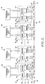
- FIGURE 2 is a schematic diagram of a current mode data transmission system incorporating bus couplers formed in accordance with this invention;
- FIGURE 3 is a longitudinal cross-sectional view of the current mode bus coupler illustrated in FIGURE 1, taken along line 3-3;
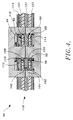
- FIGURE 4 shows a cross-sectional view of a current mode bus coupler formed in accordance with the invention having more planar coils than the bus coupler illustrated in FIGURES 1 and 3;
- FIGURE 5A shows the stray capacitance that exists between a bus coupler and a current mode data bus cable, FIGURE 5B shows a planar shield formed in accordance with the invention, and FIGURE 5C illustrates schematically the effect of the planar shield on stray capacitance; and
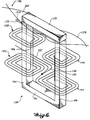
- FIGURE 6 pictorially illustrates another alternative embodiment of a current mode bus coupler formed in accordance with the invention.
- FIGURE 1 is an exploded view of the presently preferred form of a current
mode bus coupler 10 formed in accordance with the present invention. Thebus coupler 10 illustrated in FIGURE 1 comprises aferromagnetic core 12, and asandwich 14 of alternating conductive and dielectric layers. For ease of illustration, the insulating adhesive layers that join the layers of thesandwich 14 together are not illustrated in FIGURE 1. The conductive layers include upper and lowerplanar coils planar shields bus coupler 10 is electromagnetically coupled to adata bus cable 24 comprising a twisted wire pair. The wires of the twisted wire pair are covered with insulation and electrically connected at their ends throughtermination resistors 25. The value of the termination resistor Rc is equal to the characteristic impedance Zc of the twisted wirepair data bus 24. - As shown schematically in FIGURE 2, a plurality of current mode bus couplers of the type shown in FIGURE 1 can be used to form a
data transmission system 26. More specifically, thedata transmission system 26 comprises thedata bus cable 24 and a plurality of terminal couplers (TC) 30. Each of theterminal couplers 30 includes: a transmit currentmode bus coupler 10 and associateddriver circuitry 34; and a receive current mode bus coupler 10' and associated receiver circuity 34'. The driver/receiver circuitry 34 and 34' interface thebus couplers 10 and 10' toterminal units 28. Thedata transmission system 26 interconnects theterminal units 28 such that theterminal units 28 can communicate with each other, e.g., send data from one terminal unit to another terminal unit via thedata bus cable 24. For example, if thedata transmission system 26 is used in an aircraft, theterminal units 28 would include flight and navigational avionic subsystems and flight control subsystems. As required, the avionic subsystems can send commands to control subsystems using thedata transmission system 26, the avionic control systems can send data back and forth, etc. - The current
mode bus couplers 10 and 10' create a transformer-type coupling with thedata bus cable 24. As shown schematically in FIGURE 2, each transmitbus coupler 10 includes a fixed winding 32 that serves as one winding of the transformer-type coupling. A loop of the twisted wirepair data bus 24 forms a single turn second winding 35. As explained more fully below, the bus coupler winding 32 and the single-turn bus winding 35 are electromagnetically coupled together by theferromagnetic core 12. The receive bus couplers 10' have the same structure as the transmitbus couplers 10. To transmit data, thedriver circuitry 34 of theterminal coupler 30 applies time-varying current signals to the bus coupler winding 32, which induces corresponding differential time-varying current signals in thetwisted wire pair 24. To receive data, the receive bus coupler 10' senses differential time-varying current signals propagating on thetwisted wire pair 24 and induces corresponding time-varying signals in the bus coupler winding 32' for amplification and detection by the receive circuitry 34'. - Shown exploded in FIGURE 1 and assembled in FIGURE 3, the
sandwich 14 of alternating dielectric and conductive layers has threeapertures apertures aperture 37 lying between theapertures ferromagnetic core 12 comprises twoE-shaped elements lower core element 40 are inserted in the apertures from below the sandwich, and the legs of theupper core element 42 are inserted from above the sandwich. The legs of the core elements are joined at their ends when inserted into the apertures of thesandwich 14. Thus, a "figure 8"ferromagnetic core 12 having a central leg and two outer legs is formed. - The planar coils 16 and 18 are formed in the
sandwich 14 about thecentral aperture 37. Both the upper and lower planar coils spiral outward from thecentral aperture 37. The upperplanar coil 16 is formed in a plane above the plane in which the lowerplanar coil 18 is formed. As shown in FIGURE 3, the planar coils are connected in series at their inner ends 44 and 46 with a conductively plated through-hole 48, i.e., a connective path extending between the planes of the coils. As shown in FIGURE 1, theouter end 50 of the upperplanar coil 16 forms one terminal of that planar coil, and theouter end 52 of the lowerplanar coil 18 forms one terminal of that planar coil. The upper and lower planar coils are wound such that an electrical current flowing from theouter end 52 of the lowerplanar coil 18 to theouter end 50 of the upperplanar coil 16 encircles thecentral aperture 37 with the same clockwise/counterclockwise sense in both the upper and lower planar coils, i.e., the upper and lower planar coils have the same magnetic sense. This is accomplished by forming the upper and lower planar coils with opposite clockwise/counterclockwise spiraling senses, e.g., in FIGURE 1 the lowerplanar coil 18 spirals outwardly in a counterclockwise manner and the upperplanar coil 16 spirals outwardly in a clockwise manner. As a result, a current flowing from the planar coils produces additive magnetic flux rather than subtractive magnetic flux. The thusly series-connected upper and lower planar coils form the bus coupler winding 32 shown in FIGURE 2. The number of winding turns is equal to the number of turns in the lowerplanar coil 18 plus the number of turns in the upperplanar coil 16. - The
ferromagnetic core 12 provides a low reluctance path for magnetic flux that passes through thecentral aperture 37. As shown in FIGURE 1, the central leg of theupper core element 42 is surrounded by aloop 56 formed by the twistedwire pair 24, one wire passing between the center leg and one of the outer legs and the other wire passing between the center leg and the other outer leg. As a result, theloop 56 forms a one-turn winding on theferromagnetic core 42, and electromagnetically couples thetwisted wire pair 24 to theplanar coils planar coils - As shown in FIGURES 1 and 3, a
conductive lead 54 is connected to the conductive plated through-hole 48 that interconnects the upper and lower planar coils. Thelead 54 serves as a center tap of the winding formed by the series connected planar coils. Thecenter tap 54 allows the upperplanar coil 16 to serve as a first winding and the lowerplanar coil 18 to serve as a second winding. The center tapped coil allows thebus coupler 10 to be used to create bipolar data signals on the bus. This can be accomplished by connecting the positive terminal of a driver DC voltage to thecenter tap 54 and switching the negative terminal between the outer ends 50 and 52 of the upper and lower planar coils. -
Slots planar shields outer apertures central aperture 37. For example, in the upperplanar shield 20, theslot 58, which can best be seen in FIGURE 5B, extends from theouter aperture 36 to thecentral aperture 37. The slots are non-conductive and extend through the entire thickness of the conductive planar shields. - The upper and lower planar shields shield the planar coils within the
sandwich 14 from external electromagnetic flux lines, i.e., time-varying electric and magnetic flux lines, and electrostatic flux lines. Such shielding is important because electromagnetic and electrostatic flux lines could create electrical signals in the planar coils that could interfere with the operation of the bus coupler. As shown in FIGURE 1, the upper and lower planar shields are each connected to acommon ground 74, such as the return voltage-plane of an aircraft's electrical system. Grounding of the planar shields is important because ungrounded shields are ineffective against electrostatic fields. To provide effective electromagnetic shielding, the upper and lower planar shields must be of adequate thickness. The thickness required increases with the frequency of the electromagnetic flux; 3.175 mm (1.25 mils) is adequate for shielding electromagnetic flux ordinarily encountered within an aircraft for a bus having a data rate in the 30 MHz range. - While the planar shields will not block magnetostatic flux lines from flowing through the
sandwich 14, magnetostatic flux lines will not affect the operation of the bus coupler unless they are strong enough to saturate theferromagnetic core 12. Additionally, while external time-varying magnetic flux lines can flow through thesandwich 14 via the legs of theferromagnetic core 12, the magnetic flux flows in the same direction in both the outer legs and the central leg. Because the flow of magnetic flux through the center of the planar coils and sides of the planar coils is balanced, balanced opposing inductive forces are produced. Because balanced opposing inductive forces cancel each other, they induce no net electrical currents in the planar coils. - The upper
planar shield 20 is particularly effective at shielding the planar coils from voltages, i.e., electric fields, in thetwisted wire pair 24. This is particularly important if thedata bus cable 24 is used in an airplane. Aircraft are frequently subjected to electrical storms, which can produce large voltage swings and voltage spikes in conductors such as the twisted wirepair data bus 24. As shown in FIGURE 5A, without the upperplanar shield 20, such voltage surges would induce voltages and currents in the planar coils in a current mode bus coupler 10'' formed in accordance with the invention. More specifically, without an upper planar shield, electrostatic coupling would exist between the winding 32'' of the bus coupler 10'' and the data bus cable 24'' with which the bus coupler 10'' is used. The electrostatic coupling can be depicted asstray capacitance - As shown in FIGURE 5C, the upper
planar shield 20, which is shown in FIGURE 5B, eliminates thestray capacitance planar shield 20 is connected to thecommon ground 74, stray capacitance associated with the upper planar shield is grounded. This includesstray capacitance 70 between the upperplanar shield 20 and the bus coupler winding 32, andstray capacitance planar shield 20 and thetwisted wire pair 24. Grounded stray capacitances are not detrimental to the operation of the current mode bus coupler. The end result is the elimination of electrostatic coupling between thetwisted wire pair 24 and the bus coupler winding 32. - As illustrated in FIGURE 5B, the
slots planar shield 20 prevent the upper planar shield from formingconductive paths apertures ferromagnetic core 12. Shorted winding turns around any of the legs of theferromagnetic core 12 would significantly reduce, or eliminate altogether, the electromagnetic coupling between theplanar coils twisted wire pair 24. The lowerplanar shield slots - As shown in FIGURES 1 and 3, the
sandwich 14 can include adielectric layer 121 on top of the upperplanar shield 20. Thedielectric layer 121 separates the twistedwire pair 24 and the upperplanar shield 20, and provides insulation between thewires 24 and the upperplanar shield 20 in addition to that provided by the insulation on the wires themselves. Effectively, the dielectric layer decreases the chance of voltage surges on the twisted wire pair arcing to the upper planar shield and affecting the operation of thebus coupler 10. Similarly, a dielectric layer could be added beneath the lowerplanar shield 22 if the lower planar shield is exposed to high voltages. - As will be appreciated from the foregoing description, the current
mode bus coupler 10 shown in FIGURES 1 and 3 has two planar coils: the upperplanar coil 16, and the lowerplanar coil 18. As shown, each planar coil has four turns. Therefore, when the planar coils are connected in series in the manner described above, the composite winding has eight turns with a center tap. If additional turns are needed, the planar coils can be formed with more turns or additional planar coils can be used. - FIGURE 4 illustrates an example of a current mode bus coupler formed in accordance with the invention having more than two planar coils. Specifically, FIGURE 4 is a cross-sectional view of a current
mode bus coupler 86 having four planar coils. Other than the additional planar coils, thebus coupler 86 has the same structure as thebus coupler 10 shown in FIGURES 1 and 3. The FIGURE 4 currentmode bus coupler 86 includes a lowerplanar coil 88, a lower middleplanar coil 90, an upper middleplanar coil 92, and an upperplanar coil 94. The planar coils are all connected in series. Theinner end 96 of the lowerplanar coil 88 is connected by a through-hole 98 to theinner end 100 of the lower middleplanar coil 90, theouter end 102 of the lower middleplanar coil 90 is connected by a through-hole 104 to the outer end to 106 of the upper middleplanar coil 92, and theinner end 108 of the upper middleplanar coil 92 is connected by a through-hole 110 to theinner end 112 of the upperplanar coil 94. Preferably, each of the planar coils is formed with an orientation such that an electrical current flowing through each of the planar coils from theouter end 114 of the lowerplanar coil 88 to theouter end 116 of the upperplanar coil 94 encircles the central core leg with the same clockwise/counterclockwise sense when passing through each planar coil. The planar coils can be center tapped by forming a terminal lead connected to the through-hole 104. For example, a conductive path could be connected to theouter end 106 of the upper middle planar coil and extend out the left side of thesandwich 118, in the same plane as the upper middleplanar coil 92. - In addition to being expanded to include additional planar coils, the multiple planar coils of structures, such as those shown in FIGURES 3 and 4, could be interconnected to form two or more separate windings. For example, four of the planar coils of an eight planar coil current mode bus coupler formed in accordance with the invention could be interconnected with through-holes to form one winding, and the other four planar coils interconnected with through-holes to form a second winding. The two windings could serve the same function, with one of the windings providing redundancy in case the other winding fails.
- The bus coupler of the present invention can be used as a transmitter or a receiver, or both. The
terminal couplers 30 shown in FIGURE 2 include two bus couplers, one serving as a transmitter and the other as a receiver. As shown in FIGURE 2, preferably the fixed winding 32' of the receive bus coupler 10' has more turns than the fixed winding 32 of the transmitbus coupler 10, so that the receive bus coupler 10' is more sensitive to signals flowing on thedata bus cable 24. - Preferably, current
mode bus couplers 10 formed in accordance with the present invention are formed using existing technologies. For example, thesandwich 14 shown in FIGURES 1 and 3 of alternating conductive and dielectric layers can be formed using printed circuit board fabrication techniques. The formation of thesandwich 14 begins with upper, middle and lowerdielectric substrates dielectric substrate 118 and etched to form the slotted upperplanar shield 20. A thin layer of conductive material, e.g., copper, is deposited on the upper surface of the middledielectric substrate 120 and etched to form the upperplanar coil 16. The lowerplanar coil 18 is formed on the upper surface of the lowerdielectric substrate 122 in a similar manner. Thecenter tap terminal 54 is formed by depositing and suitably etching a thin strip of conductive material on the lower surface of the middledielectric substrate 120. Conductive material would also be deposited on the lower surface of the lowerdielectric substrate 122 and etched to form the slotted lowerplanar shield 22. After being formed, the upper, middle and lower dielectric substrates are bonded together with a dielectric adhesive, such as a resin. Preferably, the middledielectric substrate 120 is first adhered to the lowerdielectric substrate 102 with a layer ofdielectric adhesive 124, shown in FIGURE 3. The through-hole 48 is then drilled from theinner end 44 of the upper planar coil to theinner end 46 of the lower planar coil and plated with a conductive material. The upperdielectric substrate 118 is then adhered to the middle dielectric substrate with alayer 126 of dielectric adhesive. If used, thedielectric layer 121 would also be formed of printed circuit board dielectric material and would be adhered to the surface of the upperplanar shield 20. If not previously formed, theapertures sandwich 14 with, for example, a punch, a drill and broach, or a laser cutter. - The
sandwich 118 of the currentmode bus coupler 86 shown in FIGURE 4 can be formed in a similar way, except that additional fabrication steps are needed to form the upperplanar coil 94 on the lower surface of an upperdielectric substrate 125 and to form the lower middleplanar coil 90 on the lower surface of a middledielectric substrate 123. As in the two-coil embodiment shown in FIGURE 3, the lowerplanar coil 88 would be formed on the upper surface of a lowerdielectric substrate 127. Thedielectric substrates holes - An alternative form of the current mode bus coupler formed in accordance with the invention is schematically illustrated in FIGURE 6. In this embodiment, the
ferromagnetic core 128 comprises an I-shaped element 130 and aU-shaped element 132, which are separably joined to form a rectangle. TheU-shaped element 132 has aleft leg 134 and aright leg 136. Planar coils are shown spiraling about both theleft leg 134 and theright leg 136. The planar coils are formed in a sandwich structure (not shown) similar to the sandwich structures shown in FIGURES 1, 3, and 4. For simplicity, and to emphasize the alternative features, only the planar coils are illustrated in FIGURE 6. The sandwich is formed with two apertures for receiving the legs of theU-shaped element 132. The planar coils are formed in the sandwich so as to spiral outward from the apertures. - The embodiment illustrated in FIGURE 6 includes a left set of upper and lower
planar coils left leg 134 of theferromagnetic core 128, and a right set of upper and lowerplanar coils right leg 136. The left set upper and lowerplanar coils hole 146. Similarly, the right set upper and lowerplanar coils hole 148. The outer end of the left, lowerplanar coil 140 is connected to the outer end of the right, lowerplanar coil 144 with aconductive trace 150. Aconductive trace 152 is connected to the outer end of the left, upperplanar coil 138 to form one terminal, and aconductive trace 154 is connected to the outer end of the right, upperplanar coil 142 to form another terminal. In this manner, the four planar coils are connected in series to provide a single winding with theterminals conductive trace 155 connected to theconductive trace 150 that interconnects the lowerplanar coils terminals ferromagnetic core 128. The concept illustrated in FIGURE 6 can be readily expanded to include additional left leg and right leg coils. The current mode bus coupler illustrated in FIGURE 6 would be inserted in atwisted wire 156 by means of theseparable core elements 130 and 132. The I-shaped core element 130 would be removed and the right and left legs of theU-shaped element 132 would be inserted through a pair ofadjacent loops twisted wire pair 156. - While preferred embodiments of the invention have been illustrated and described, it will be appreciated that various changes, in addition to those previously mentioned herein, can be made therein without departing from the scope of the invention. For example, the current mode bus coupler could be enclosed with a casing that provides additional shielding, e.g., a casing formed of a conductive material. Thus, within the scope of the appended claims it is to be understood that the invention can be practiced otherwise then as specifically described herein.
Claims (17)
- A current mode data transmission system for communicating among a plurality of electronic terminal units, comprising:(a) a data bus (24) including two wires insulated from each other, and electrically terminated at both ends, said two wires being twisted along their lengths to form a plurality of loops (56); and(b) at least one current mode bus coupler for electromagnetically coupling an electronic terminal unit with said data bus, said at least one bus coupler, characterized by:(c) a dielectric substrate (120) having an aperture (37);(d) an electrically conductive planar coil (16) formed on said dielectric substrate so as to surround said first aperture (37) and spiral outwardly therefrom;(e) an electrically conductive planar shield (20) located on one side of said dielectric substrate (120), said planar shield (20) including an aperture aligned with the aperture (37) of said dielectric substrate, said planar shield including a slot (58, 60) that extends outwardly from said aperture in said planar shield; and(f) ferromagnetic core (12) formed of two separable elements (40, 42) that when joined together form at least one closed magnetic path, one of said separable elements including a leg mounted in said aperture (37) in said dielectric substrate and said planar shield, said separable elements separable to allow a loop (56) of said data bus to be positioned about said leg on the opposite side of said planar shield (20) from said planar coil (16).
- The current mode data transmission system claimed in claim 1, wherein:said dielectric substrate (120) and said planar shield (20) each have a second aperture (36);one of said ferromagnetic core elements includes a second leg magnetically coupled to said first leg when said separable core elements (40, 42) are joined together; andsaid second leg is mounted in said second aperture (36) said planar shield includes a second slot that extends outwardly from said second aperture.
- The current mode data transmission system claimed in claim 2, wherein said slots merge into one another.
- The current mode data transmission system claimed in claim 2 wherein:said dielectric substrate (120) and said planar shield (20) each have a third aperture (38);one of said ferromagnetic core elements (40, 42) includes a third leg magnetically coupled to said first and second legs when said separable core elements are joined together;said third leg is mounted in said third aperture (38); andsaid planar shield (20) includes a slot (58,60) that extends outwardly from said third aperture.
- The current mode data transmission system claimed in claim 4, wherein said slots (58, 60) extend between said first (37), second and third apertures (36, 38).
- The current mode data transmission system claimed in claim 4, wherein said ferromagnetic core comprises two E-shaped elements whose legs, when joined, form said first, second, and third legs.
- The current mode data transmission system claimed in claim 6, said at least one bus coupler, characterized by a second electrically conductive planar shield (22) located on the other side of said dielectric substrate (120) from said first planar shield (20), said second planar shield including first, second, and third apertures aligned with said first, second and third apertures in said dielectric substrate (120) and said first planar shield for respectively receiving said first, second, and third legs of said ferromagnetic core, said second planar shield including slots that extend outwardly from said first and third apertures in said second planar shield.
- The current mode data transmission system claimed in claim 7, wherein said slots in said first and second planar shields extend between their respective first, second and third apertures.
- The current mode data transmission system claimed in claim 7, said at least one bus coupler further comprising a second electrically conductive planar coil (18), said second planar coil spaced from said first planar coil and positioned between said first and second planar shields (20, 22), said second planar coil (18) positioned so as to surround one of said legs of said ferromagnetic core and spiral outwardly therefrom and electrically connected to the first planar coil, so that the fluxes in the coils cooperate.
- The current mode data transmission system claimed in claim 9, wherein said first (16) and second (18) planar coils surround the same leg of said ferromagnetic core.
- The current mode data transmission system claimed in claim 10, wherein the spiral direction of said first and second planar coils have the opposite clockwise/conterclockwise sense.
- The current mode data transmission system claimed in claim 9, said at least one bus coupler further including:a second (118) dielectric substrate, said first (20) planar shield being formed on said second dielectric substrate; anda third (122) dielectric substrate, said second planar shield (22) and said second planar coil (18) being formed on opposite sides of said third (122) dielectric substrate.
- The current mode data transmission system claimed in claim 12, wherein:said first dielectric substrate (120) is adhesively (124) attached with a dielectric adhesive to the side of said third (122) dielectric substrate on which said second planar coil (18) is formed; andsaid second (118) dielectric substrate is adhesively (124) attached with a dielectric adhesive to the side of said first (120) dielectric substrate opposite to the side attached to said third dielectric substrate (122).
- The current mode data transmission system for communicating among a plurality of electronic terminal units claimed in claim 2, wherein said ferromagnetic core (12) includes a U-shaped element whose legs form said first and second legs and an I-shaped element positionable across the ends of the legs of said U-shaped element.
- The current mode data transmission system claimed in claim 14, said at least one bus coupler characterized by a second (22) electrically conductive planar shield located on the other side of said dielectric substrate (120) from said first planar shield (20), said second planar shield including first and second apertures aligned with said first and second apertures in said dielectric substrate and said first planar shield for respectively receiving said first and second legs of said ferromagnetic core, said second planar shield including a slot that extends outwardly from said first aperture in said second planar shield.
- The current mode data transmission system claimed in claim 15, wherein said slots in said first (20) and second (22) planar shields extend between their respective first and second apertures.
- The current mode data transmission system claimed in claims 1, 3, 5, 8, 11, 13 or 16 wherein the side of said first planar shield opposite from said first planar coil is covered with a dielectric material (12).
Applications Claiming Priority (2)
| Application Number | Priority Date | Filing Date | Title |
|---|---|---|---|
| US64816191A | 1991-01-30 | 1991-01-30 | |
| US648161 | 1991-01-30 |
Publications (3)
| Publication Number | Publication Date |
|---|---|
| EP0507360A2 EP0507360A2 (en) | 1992-10-07 |
| EP0507360A3 EP0507360A3 (en) | 1993-03-10 |
| EP0507360B1 true EP0507360B1 (en) | 1996-05-08 |
Family
ID=24599681
Family Applications (1)
| Application Number | Title | Priority Date | Filing Date |
|---|---|---|---|
| EP92200239A Expired - Lifetime EP0507360B1 (en) | 1991-01-30 | 1992-01-28 | Current mode bus coupler with planar coils and shields |
Country Status (2)
| Country | Link |
|---|---|
| EP (1) | EP0507360B1 (en) |
| DE (1) | DE69210458T2 (en) |
Cited By (1)
| Publication number | Priority date | Publication date | Assignee | Title |
|---|---|---|---|---|
| US7468648B2 (en) | 2004-03-10 | 2008-12-23 | Det International Holding Limited | Magnetic device |
Families Citing this family (43)
| Publication number | Priority date | Publication date | Assignee | Title |
|---|---|---|---|---|
| DE4412957A1 (en) * | 1994-04-17 | 1995-10-19 | Schwan Ulrich | Transmission device |
| US5461353A (en) * | 1994-08-30 | 1995-10-24 | Motorola, Inc. | Printed circuit board inductor |
| DE69619420T2 (en) * | 1995-03-29 | 2002-10-31 | Valeo Electronique Creteil | Transformer device, in particular for a supply device for discharge lamps in motor vehicles |
| US5640170A (en) * | 1995-06-05 | 1997-06-17 | Polhemus Incorporated | Position and orientation measuring system having anti-distortion source configuration |
| FR2735309B1 (en) * | 1995-06-08 | 1997-07-18 | Framatome Connectors France | ELECTROMAGNETIC COUPLERS DISTRIBUTION NETWORK |
| US5650778A (en) * | 1995-06-30 | 1997-07-22 | Bio Medic Data Systems, Inc. | Antenna for programming a transponder |
| DE19627819B4 (en) * | 1996-07-10 | 2005-12-01 | Weiner, René | Spool for a flat coil |
| EP0926690A4 (en) * | 1997-07-03 | 2000-12-20 | Furukawa Electric Co Ltd | Split transformer and transmission controller comprising the split transformer |
| ES2270549T3 (en) * | 1998-06-23 | 2007-04-01 | Meto International Gmbh | IDENTIFICATION ELEMENT. |
| US6324430B1 (en) | 1998-07-06 | 2001-11-27 | Abiomed, Inc. | Magnetic shield for primary coil of transcutaneous energy transfer device |
| US6324431B1 (en) | 1998-07-06 | 2001-11-27 | Abiomed, Inc. | Transcutaneous energy transfer device with magnetic field protected components in secondary coil |
| US6389318B1 (en) * | 1998-07-06 | 2002-05-14 | Abiomed, Inc. | Magnetic shield for primary coil of transcutaneous energy transfer device |
| US8489200B2 (en) | 1998-07-06 | 2013-07-16 | Abiomed, Inc. | Transcutaneous energy transfer module with integrated conversion circuitry |
| AU7369701A (en) * | 2000-06-08 | 2001-12-17 | Herman Allison | Lighting assembly |
| US6489876B1 (en) * | 2000-09-22 | 2002-12-03 | Ascom Energy Systems Ag | Method and apparatus for forming a magnetic component on a printed circuit board |
| WO2004040599A1 (en) * | 2002-10-31 | 2004-05-13 | Delta Energy Systems (Switzerland) Ag | A circuit board with a planar magnetic element |
| GB201011085D0 (en) * | 2010-07-01 | 2010-08-18 | Micromass Ltd | Improvements in planar transformers particularly for use in ion guides |
| US10146281B2 (en) | 2010-08-31 | 2018-12-04 | Delta Electronics Thailand Public Company Limited | Method and apparatus for load identification |
| ES2731918T3 (en) | 2010-12-20 | 2019-11-19 | Abiomed Inc | Transcutaneous energy transfer system with multiple secondary coils |
| US8766788B2 (en) | 2010-12-20 | 2014-07-01 | Abiomed, Inc. | Transcutaneous energy transfer system with vibration inducing warning circuitry |
| JP2014502528A (en) | 2010-12-20 | 2014-02-03 | アビオメド インコーポレイティド | Method and apparatus for accurately tracking charge available in a transdermal energy transmission system |
| DK3485819T3 (en) | 2011-04-14 | 2022-10-17 | Abiomed Inc | TRANSCUTANEOUS ENERGY TRANSFER COIL WITH INTEGRATED RADIO FREQUENCY ANTENNA |
| US9002468B2 (en) | 2011-12-16 | 2015-04-07 | Abiomed, Inc. | Automatic power regulation for transcutaneous energy transfer charging system |
| US9531299B2 (en) | 2011-12-28 | 2016-12-27 | Det International Holding Limited | Resonant single stage DC-AC converter with capacitors forming a half-bridge |
| US8862802B2 (en) * | 2011-12-30 | 2014-10-14 | Bedrock Automation Platforms Inc. | Switch fabric having a serial communications interface and a parallel communications interface |
| US11144630B2 (en) | 2011-12-30 | 2021-10-12 | Bedrock Automation Platforms Inc. | Image capture devices for a secure industrial control system |
| US9600434B1 (en) | 2011-12-30 | 2017-03-21 | Bedrock Automation Platforms, Inc. | Switch fabric having a serial communications interface and a parallel communications interface |
| US8971072B2 (en) | 2011-12-30 | 2015-03-03 | Bedrock Automation Platforms Inc. | Electromagnetic connector for an industrial control system |
| US8868813B2 (en) | 2011-12-30 | 2014-10-21 | Bedrock Automation Platforms Inc. | Communications control system with a serial communications interface and a parallel communications interface |
| US9437967B2 (en) | 2011-12-30 | 2016-09-06 | Bedrock Automation Platforms, Inc. | Electromagnetic connector for an industrial control system |
| US11314854B2 (en) | 2011-12-30 | 2022-04-26 | Bedrock Automation Platforms Inc. | Image capture devices for a secure industrial control system |
| US9727511B2 (en) | 2011-12-30 | 2017-08-08 | Bedrock Automation Platforms Inc. | Input/output module with multi-channel switching capability |
| US10834820B2 (en) | 2013-08-06 | 2020-11-10 | Bedrock Automation Platforms Inc. | Industrial control system cable |
| US9191203B2 (en) | 2013-08-06 | 2015-11-17 | Bedrock Automation Platforms Inc. | Secure industrial control system |
| US10834094B2 (en) | 2013-08-06 | 2020-11-10 | Bedrock Automation Platforms Inc. | Operator action authentication in an industrial control system |
| EP3264564A1 (en) | 2012-05-04 | 2018-01-03 | DET International Holding Limited | Multiple resonant cells for inductive charging pads |
| US9196417B2 (en) | 2012-05-04 | 2015-11-24 | Det International Holding Limited | Magnetic configuration for high efficiency power processing |
| US20130314188A1 (en) | 2012-05-04 | 2013-11-28 | Ionel Jitaru | Magnetic Structure for Large Air Gap |
| US10553351B2 (en) * | 2012-05-04 | 2020-02-04 | Delta Electronics (Thailand) Public Co., Ltd. | Multiple cells magnetic structure for wireless power |
| US9494631B2 (en) | 2012-05-04 | 2016-11-15 | Det International Holding Limited | Intelligent current analysis for resonant converters |
| US10613567B2 (en) | 2013-08-06 | 2020-04-07 | Bedrock Automation Platforms Inc. | Secure power supply for an industrial control system |
| DE102014002298B3 (en) * | 2014-02-20 | 2015-01-08 | Fraunhofer-Gesellschaft zur Förderung der angewandten Forschung e.V. | Device for the potential-separated transmission of control signals for a cascaded high-voltage switch |
| EP3048618B1 (en) * | 2015-01-20 | 2019-05-29 | Nexperia B.V. | Common mode choke |
Family Cites Families (1)
| Publication number | Priority date | Publication date | Assignee | Title |
|---|---|---|---|---|
| US4264827A (en) * | 1978-11-06 | 1981-04-28 | The Boeing Company | Current mode data or power bus |
-
1992
- 1992-01-28 DE DE69210458T patent/DE69210458T2/en not_active Expired - Fee Related
- 1992-01-28 EP EP92200239A patent/EP0507360B1/en not_active Expired - Lifetime
Cited By (1)
| Publication number | Priority date | Publication date | Assignee | Title |
|---|---|---|---|---|
| US7468648B2 (en) | 2004-03-10 | 2008-12-23 | Det International Holding Limited | Magnetic device |
Also Published As
| Publication number | Publication date |
|---|---|
| DE69210458T2 (en) | 1996-09-05 |
| EP0507360A3 (en) | 1993-03-10 |
| EP0507360A2 (en) | 1992-10-07 |
| DE69210458D1 (en) | 1996-06-13 |
Similar Documents
| Publication | Publication Date | Title |
|---|---|---|
| EP0507360B1 (en) | Current mode bus coupler with planar coils and shields | |
| US4605915A (en) | Stripline circuits isolated by adjacent decoupling strip portions | |
| US4264827A (en) | Current mode data or power bus | |
| US5801602A (en) | Isolation and signal filter transformer | |
| EP0069102B1 (en) | Impedance matching stripline transition for microwave signals | |
| EP0391527B1 (en) | Circuit board configuration for reducing signal distortion | |
| EP0632516B1 (en) | Dielectric filter | |
| US6002593A (en) | Reducing electromagnetic noise radiated from a printed board | |
| EP1417691B1 (en) | Planar inductive component and a planar transformer | |
| EP0400885A1 (en) | Printed circuit having twisted conductor lines printed thereon | |
| US3689865A (en) | Connector | |
| US9312062B2 (en) | Common mode choke coil | |
| US5083101A (en) | Integrated electromagnetic interference filter | |
| US7253713B2 (en) | Common-mode choke coil | |
| US6924724B2 (en) | Method and apparatus for transformer bandwidth enhancement | |
| US7342477B2 (en) | Inductor | |
| US10038421B2 (en) | Common mode filter | |
| US20040150502A1 (en) | Electrical transformer | |
| GB2083952A (en) | Microcoil Assembly | |
| EP1506592A1 (en) | Miniature directional coupler | |
| CN115299184A (en) | Circuit board and electronic device | |
| EP0396516B1 (en) | Filter device for suppressing radio-frequency interferences on transmission lines | |
| EP0098066A1 (en) | A data transmission system | |
| JPS62139395A (en) | Multi-function circuit board | |
| GB2165359A (en) | Well logging receiver coil apparatus |
Legal Events
| Date | Code | Title | Description |
|---|---|---|---|
| PUAI | Public reference made under article 153(3) epc to a published international application that has entered the european phase |
Free format text: ORIGINAL CODE: 0009012 |
|
| AK | Designated contracting states |
Kind code of ref document: A2 Designated state(s): DE FR GB IT NL |
|
| PUAL | Search report despatched |
Free format text: ORIGINAL CODE: 0009013 |
|
| AK | Designated contracting states |
Kind code of ref document: A3 Designated state(s): DE FR GB IT NL |
|
| 17P | Request for examination filed |
Effective date: 19930827 |
|
| 17Q | First examination report despatched |
Effective date: 19941205 |
|
| GRAA | (expected) grant |
Free format text: ORIGINAL CODE: 0009210 |
|
| AK | Designated contracting states |
Kind code of ref document: B1 Designated state(s): DE FR GB IT NL |
|
| REF | Corresponds to: |
Ref document number: 69210458 Country of ref document: DE Date of ref document: 19960613 |
|
| ITF | It: translation for a ep patent filed |
Owner name: STUDIO INGG. FISCHETTI & WEBER |
|
| ET | Fr: translation filed | ||
| PLBE | No opposition filed within time limit |
Free format text: ORIGINAL CODE: 0009261 |
|
| STAA | Information on the status of an ep patent application or granted ep patent |
Free format text: STATUS: NO OPPOSITION FILED WITHIN TIME LIMIT |
|
| 26N | No opposition filed | ||
| REG | Reference to a national code |
Ref country code: GB Ref legal event code: IF02 |
|
| PGFP | Annual fee paid to national office [announced via postgrant information from national office to epo] |
Ref country code: IT Payment date: 20060131 Year of fee payment: 15 |
|
| PGFP | Annual fee paid to national office [announced via postgrant information from national office to epo] |
Ref country code: NL Payment date: 20070124 Year of fee payment: 16 |
|
| NLV4 | Nl: lapsed or anulled due to non-payment of the annual fee |
Effective date: 20080801 |
|
| PG25 | Lapsed in a contracting state [announced via postgrant information from national office to epo] |
Ref country code: NL Free format text: LAPSE BECAUSE OF NON-PAYMENT OF DUE FEES Effective date: 20080801 |
|
| PGFP | Annual fee paid to national office [announced via postgrant information from national office to epo] |
Ref country code: DE Payment date: 20090302 Year of fee payment: 18 |
|
| PGFP | Annual fee paid to national office [announced via postgrant information from national office to epo] |
Ref country code: GB Payment date: 20090129 Year of fee payment: 18 |
|
| PG25 | Lapsed in a contracting state [announced via postgrant information from national office to epo] |
Ref country code: IT Free format text: LAPSE BECAUSE OF NON-PAYMENT OF DUE FEES Effective date: 20070128 |
|
| PGFP | Annual fee paid to national office [announced via postgrant information from national office to epo] |
Ref country code: FR Payment date: 20090119 Year of fee payment: 18 |
|
| GBPC | Gb: european patent ceased through non-payment of renewal fee |
Effective date: 20100128 |
|
| REG | Reference to a national code |
Ref country code: FR Ref legal event code: ST Effective date: 20100930 |
|
| PG25 | Lapsed in a contracting state [announced via postgrant information from national office to epo] |
Ref country code: FR Free format text: LAPSE BECAUSE OF NON-PAYMENT OF DUE FEES Effective date: 20100201 |
|
| PG25 | Lapsed in a contracting state [announced via postgrant information from national office to epo] |
Ref country code: DE Free format text: LAPSE BECAUSE OF NON-PAYMENT OF DUE FEES Effective date: 20100803 |
|
| PG25 | Lapsed in a contracting state [announced via postgrant information from national office to epo] |
Ref country code: GB Free format text: LAPSE BECAUSE OF NON-PAYMENT OF DUE FEES Effective date: 20100128 |