EP0507600A1 - Roll stamper and apparatus for forming a substrate for information recording medium - Google Patents
Roll stamper and apparatus for forming a substrate for information recording medium Download PDFInfo
- Publication number
- EP0507600A1 EP0507600A1 EP92302945A EP92302945A EP0507600A1 EP 0507600 A1 EP0507600 A1 EP 0507600A1 EP 92302945 A EP92302945 A EP 92302945A EP 92302945 A EP92302945 A EP 92302945A EP 0507600 A1 EP0507600 A1 EP 0507600A1
- Authority
- EP
- European Patent Office
- Prior art keywords
- stamper
- roll
- fixation
- fixation member
- tensile force
- Prior art date
- Legal status (The legal status is an assumption and is not a legal conclusion. Google has not performed a legal analysis and makes no representation as to the accuracy of the status listed.)
- Granted
Links
- 239000000758 substrate Substances 0.000 title claims abstract description 34
- 239000011347 resin Substances 0.000 claims abstract description 40
- 229920005989 resin Polymers 0.000 claims abstract description 40
- 238000002844 melting Methods 0.000 claims abstract description 3
- 230000008018 melting Effects 0.000 claims abstract description 3
- 238000003825 pressing Methods 0.000 claims description 24
- 238000004519 manufacturing process Methods 0.000 claims description 17
- 239000000463 material Substances 0.000 claims description 11
- 229910001285 shape-memory alloy Inorganic materials 0.000 claims description 3
- 238000000034 method Methods 0.000 description 26
- 230000003287 optical effect Effects 0.000 description 24
- 238000000465 moulding Methods 0.000 description 18
- 238000003466 welding Methods 0.000 description 17
- 238000010586 diagram Methods 0.000 description 13
- PXHVJJICTQNCMI-UHFFFAOYSA-N Nickel Chemical compound [Ni] PXHVJJICTQNCMI-UHFFFAOYSA-N 0.000 description 11
- 229910001220 stainless steel Inorganic materials 0.000 description 11
- 239000010935 stainless steel Substances 0.000 description 10
- 238000010438 heat treatment Methods 0.000 description 7
- 229910052759 nickel Inorganic materials 0.000 description 7
- 238000010894 electron beam technology Methods 0.000 description 6
- 230000003746 surface roughness Effects 0.000 description 6
- 229910045601 alloy Inorganic materials 0.000 description 5
- 239000000956 alloy Substances 0.000 description 5
- 238000011156 evaluation Methods 0.000 description 5
- 239000011521 glass Substances 0.000 description 5
- 229910000831 Steel Inorganic materials 0.000 description 4
- 238000001125 extrusion Methods 0.000 description 4
- 239000010408 film Substances 0.000 description 4
- 238000001746 injection moulding Methods 0.000 description 4
- 239000004431 polycarbonate resin Substances 0.000 description 4
- 239000010959 steel Substances 0.000 description 4
- VYZAMTAEIAYCRO-UHFFFAOYSA-N Chromium Chemical compound [Cr] VYZAMTAEIAYCRO-UHFFFAOYSA-N 0.000 description 3
- 239000000853 adhesive Substances 0.000 description 3
- 230000001070 adhesive effect Effects 0.000 description 3
- 238000005452 bending Methods 0.000 description 3
- 229910052804 chromium Inorganic materials 0.000 description 3
- 239000011651 chromium Substances 0.000 description 3
- 230000000694 effects Effects 0.000 description 3
- 238000005323 electroforming Methods 0.000 description 3
- 238000007667 floating Methods 0.000 description 3
- 229920002120 photoresistant polymer Polymers 0.000 description 3
- 229920005668 polycarbonate resin Polymers 0.000 description 3
- 229910001369 Brass Inorganic materials 0.000 description 2
- 229910000975 Carbon steel Inorganic materials 0.000 description 2
- BQCADISMDOOEFD-UHFFFAOYSA-N Silver Chemical compound [Ag] BQCADISMDOOEFD-UHFFFAOYSA-N 0.000 description 2
- 230000015572 biosynthetic process Effects 0.000 description 2
- 239000010951 brass Substances 0.000 description 2
- 239000010962 carbon steel Substances 0.000 description 2
- 238000000748 compression moulding Methods 0.000 description 2
- 229910052802 copper Inorganic materials 0.000 description 2
- 239000010949 copper Substances 0.000 description 2
- 238000009760 electrical discharge machining Methods 0.000 description 2
- KHYBPSFKEHXSLX-UHFFFAOYSA-N iminotitanium Chemical compound [Ti]=N KHYBPSFKEHXSLX-UHFFFAOYSA-N 0.000 description 2
- 229910052742 iron Inorganic materials 0.000 description 2
- XEEYBQQBJWHFJM-UHFFFAOYSA-N iron Substances [Fe] XEEYBQQBJWHFJM-UHFFFAOYSA-N 0.000 description 2
- 238000005259 measurement Methods 0.000 description 2
- 229910001172 neodymium magnet Inorganic materials 0.000 description 2
- 229910001000 nickel titanium Inorganic materials 0.000 description 2
- 230000005855 radiation Effects 0.000 description 2
- 229910052709 silver Inorganic materials 0.000 description 2
- 239000004332 silver Substances 0.000 description 2
- 229910000679 solder Inorganic materials 0.000 description 2
- 238000005476 soldering Methods 0.000 description 2
- 229910052725 zinc Inorganic materials 0.000 description 2
- 229910000838 Al alloy Inorganic materials 0.000 description 1
- 229910001018 Cast iron Inorganic materials 0.000 description 1
- 229910000925 Cd alloy Inorganic materials 0.000 description 1
- 229910000881 Cu alloy Inorganic materials 0.000 description 1
- 229910017535 Cu-Al-Ni Inorganic materials 0.000 description 1
- 229910017777 Cu—Al—Zn Inorganic materials 0.000 description 1
- 229910001374 Invar Inorganic materials 0.000 description 1
- 229910000792 Monel Inorganic materials 0.000 description 1
- 229910003310 Ni-Al Inorganic materials 0.000 description 1
- 229910018054 Ni-Cu Inorganic materials 0.000 description 1
- 229910018481 Ni—Cu Inorganic materials 0.000 description 1
- VRDIULHPQTYCLN-UHFFFAOYSA-N Prothionamide Chemical compound CCCC1=CC(C(N)=S)=CC=N1 VRDIULHPQTYCLN-UHFFFAOYSA-N 0.000 description 1
- 229910001007 Tl alloy Inorganic materials 0.000 description 1
- 230000001133 acceleration Effects 0.000 description 1
- 239000000919 ceramic Substances 0.000 description 1
- 238000007906 compression Methods 0.000 description 1
- 230000006835 compression Effects 0.000 description 1
- 238000010276 construction Methods 0.000 description 1
- 230000007547 defect Effects 0.000 description 1
- 238000005553 drilling Methods 0.000 description 1
- 239000012789 electroconductive film Substances 0.000 description 1
- 239000005357 flat glass Substances 0.000 description 1
- 239000011888 foil Substances 0.000 description 1
- 230000006870 function Effects 0.000 description 1
- 230000005764 inhibitory process Effects 0.000 description 1
- 239000007788 liquid Substances 0.000 description 1
- 238000003754 machining Methods 0.000 description 1
- 229910052751 metal Inorganic materials 0.000 description 1
- 239000002184 metal Substances 0.000 description 1
- 238000002156 mixing Methods 0.000 description 1
- 239000008188 pellet Substances 0.000 description 1
- 238000007747 plating Methods 0.000 description 1
- 238000004544 sputter deposition Methods 0.000 description 1
- 238000009966 trimming Methods 0.000 description 1
- 229910052726 zirconium Inorganic materials 0.000 description 1
Images


Classifications
-
- B—PERFORMING OPERATIONS; TRANSPORTING
- B29—WORKING OF PLASTICS; WORKING OF SUBSTANCES IN A PLASTIC STATE IN GENERAL
- B29C—SHAPING OR JOINING OF PLASTICS; SHAPING OF MATERIAL IN A PLASTIC STATE, NOT OTHERWISE PROVIDED FOR; AFTER-TREATMENT OF THE SHAPED PRODUCTS, e.g. REPAIRING
- B29C43/00—Compression moulding, i.e. applying external pressure to flow the moulding material; Apparatus therefor
- B29C43/22—Compression moulding, i.e. applying external pressure to flow the moulding material; Apparatus therefor of articles of indefinite length
- B29C43/222—Compression moulding, i.e. applying external pressure to flow the moulding material; Apparatus therefor of articles of indefinite length characterised by the shape of the surface
-
- B—PERFORMING OPERATIONS; TRANSPORTING
- B29—WORKING OF PLASTICS; WORKING OF SUBSTANCES IN A PLASTIC STATE IN GENERAL
- B29C—SHAPING OR JOINING OF PLASTICS; SHAPING OF MATERIAL IN A PLASTIC STATE, NOT OTHERWISE PROVIDED FOR; AFTER-TREATMENT OF THE SHAPED PRODUCTS, e.g. REPAIRING
- B29C33/00—Moulds or cores; Details thereof or accessories therefor
- B29C33/30—Mounting, exchanging or centering
- B29C33/305—Mounting of moulds or mould support plates
-
- B—PERFORMING OPERATIONS; TRANSPORTING
- B29—WORKING OF PLASTICS; WORKING OF SUBSTANCES IN A PLASTIC STATE IN GENERAL
- B29C—SHAPING OR JOINING OF PLASTICS; SHAPING OF MATERIAL IN A PLASTIC STATE, NOT OTHERWISE PROVIDED FOR; AFTER-TREATMENT OF THE SHAPED PRODUCTS, e.g. REPAIRING
- B29C59/00—Surface shaping of articles, e.g. embossing; Apparatus therefor
- B29C59/002—Component parts, details or accessories; Auxiliary operations
-
- B—PERFORMING OPERATIONS; TRANSPORTING
- B29—WORKING OF PLASTICS; WORKING OF SUBSTANCES IN A PLASTIC STATE IN GENERAL
- B29D—PRODUCING PARTICULAR ARTICLES FROM PLASTICS OR FROM SUBSTANCES IN A PLASTIC STATE
- B29D17/00—Producing carriers of records containing fine grooves or impressions, e.g. disc records for needle playback, cylinder records; Producing record discs from master stencils
- B29D17/005—Producing optically read record carriers, e.g. optical discs
- B29D17/007—Forming the relief pattern on a support larger than the record
-
- G—PHYSICS
- G11—INFORMATION STORAGE
- G11B—INFORMATION STORAGE BASED ON RELATIVE MOVEMENT BETWEEN RECORD CARRIER AND TRANSDUCER
- G11B23/00—Record carriers not specific to the method of recording or reproducing; Accessories, e.g. containers, specially adapted for co-operation with the recording or reproducing apparatus ; Intermediate mediums; Apparatus or processes specially adapted for their manufacture
- G11B23/0057—Intermediate mediums, i.e. mediums provided with an information structure not specific to the method of reproducing or duplication such as matrixes for mechanical pressing of an information structure ; record carriers having a relief information structure provided with or included in layers not specific for a single reproducing method; apparatus or processes specially adapted for their manufacture
-
- G—PHYSICS
- G11—INFORMATION STORAGE
- G11B—INFORMATION STORAGE BASED ON RELATIVE MOVEMENT BETWEEN RECORD CARRIER AND TRANSDUCER
- G11B7/00—Recording or reproducing by optical means, e.g. recording using a thermal beam of optical radiation by modifying optical properties or the physical structure, reproducing using an optical beam at lower power by sensing optical properties; Record carriers therefor
- G11B7/24—Record carriers characterised by shape, structure or physical properties, or by the selection of the material
- G11B7/26—Apparatus or processes specially adapted for the manufacture of record carriers
- G11B7/263—Preparing and using a stamper, e.g. pressing or injection molding substrates
-
- B—PERFORMING OPERATIONS; TRANSPORTING
- B29—WORKING OF PLASTICS; WORKING OF SUBSTANCES IN A PLASTIC STATE IN GENERAL
- B29L—INDEXING SCHEME ASSOCIATED WITH SUBCLASS B29C, RELATING TO PARTICULAR ARTICLES
- B29L2017/00—Carriers for sound or information
- B29L2017/001—Carriers of records containing fine grooves or impressions, e.g. disc records for needle playback, cylinder records
- B29L2017/003—Records or discs
- B29L2017/005—CD''s, DVD''s
-
- Y—GENERAL TAGGING OF NEW TECHNOLOGICAL DEVELOPMENTS; GENERAL TAGGING OF CROSS-SECTIONAL TECHNOLOGIES SPANNING OVER SEVERAL SECTIONS OF THE IPC; TECHNICAL SUBJECTS COVERED BY FORMER USPC CROSS-REFERENCE ART COLLECTIONS [XRACs] AND DIGESTS
- Y10—TECHNICAL SUBJECTS COVERED BY FORMER USPC
- Y10S—TECHNICAL SUBJECTS COVERED BY FORMER USPC CROSS-REFERENCE ART COLLECTIONS [XRACs] AND DIGESTS
- Y10S425/00—Plastic article or earthenware shaping or treating: apparatus
- Y10S425/81—Sound record
Definitions
- This invention relates to a roll stamper used to continuously manufacture a substrate for a high-density information recording medium such as an optical disk or optical card by transferring a pre-format pattern to a substrate surface, and to an apparatus for forming the high-density information recording medium substrate by using the stamper.
- an injection molding method, a compression molding method and an extrusion molding method are known as methods for manufacturing the substrate for a high-density optical recording medium such as an optical disk or optical card.
- An information recording medium substrate may be manufactured by extrusion molding in such a manner that a sheet of a molten resin extruded from an extruder is pressed by a roll stamper to form the substrate while transferring a pre-format pattern for providing a pre-format signal, a tracking signal and the like.
- extrusion molding process is therefore advantageous in terms of mass production of a substrate and has recently been studying as a method for forming an information recording medium substrate.
- Roll stampers to be used to form an information recording medium substrate by extrusion molding as described above have conventionally been manufactured by the following methods:
- the whole roll stamper In the case of the method (1), if a defect is caused in only one portion of the pre-format pattern, the whole roll stamper must be exchanged, and the molding efficiency is therefore low.
- the adhesive In the roll stamper manufactured by the method (2), the adhesive is changed in quality with time by the heat of the extruded resin sheet or the heat of the roll so that the bonding force is reduced and the stamper may easily come off the specular roll. Therefore the life of the roll stamper is very short. Moreover, air bubbles are liable to be generated in the adhesive. Unnecessary irregularities in the stamper surface caused by the air bubbles are transferred to the substrate, so that the pattern may not be formed accurately and there is a problem of resulting in transfer failure.
- the present invention has been achieved in view of the above-described conventional related art, and an object of the present invention is to provide a roll stamper used to form an information-recording medium substrate, fixed accurately and securely on a specular roll surface, having a long life, and capable of transferring only a pre-format pattern onto a resin sheet with accuracy.
- Another object of the present invention is to provide an apparatus for manufacturing an information recording medium substrate which apparatus enables a pre-format pattern to be transferred onto a resin sheet with accuracy while preventing occurrence of birefringence in the resin sheet.
- Still another object of the present invention is to provide a method of manufacturing an information recording medium substrate in which a pre-format pattern can be transferred onto a resin sheet with accuracy while occurrence of birefringence in the resin sheet is prevented.
- a roll stamper for forming an information recording medium substrate, comprising a stamper member having a pattern corresponding to a pre-format for an information recording medium formed on its obverse surface, fixation members fixed to both end portions of a reverse surface of the stamper so as to be integral with the stamper member, and fit grooves capable of fittingly receiving the fixation members and formed on a circumferential surface of a specular roll base parallel to the axis of the specular roll base, the fixation members being fitted in the fit grooves, the stamper member being fixed along the circumferential surface of the specular roll base, and means for applying a tensile force to the stamper member.
- an apparatus for continuously manufacturing an information recording medium substrate comprising means for melting and extruding a resin to form a resin sheet, a roll stamper having a pattern corresponding to a pre-format formed on its surface, and a specular roll disposed so as to face the roll stamper, the roll stamper comprising a stamper member having a pattern corresponding to a pre-format pattern for an information recording medium, fixation members fixed to both end portions of a reverse surface of the stamper so as to be integral with the stamper member, fit grooves capable of fittingly receiving the fixation members and formed in a circumferential surface of a specular roll base parallel to the axis of the specular roll base, the fixation members being fitted in the fit grooves, the stamper member being fixed along the circumferential surface of the specular roll base, and means for applying a tensile force to the stamper member.
- Fig. 1 is a perspective view of a roll stamper 5 in accordance with an embodiment of the present invention.
- the roll stamper 5 is composed of a lengthwise flexible stamper 1 having an optical card pre-format pattern 4 formed on its surface, a specular roll base 2 on which the lengthwise flexible stamper 1 is fixed, stamper fixation members 3a and 3b for fixing the stamper 1 on the roll base 2, wedges 6 constituting a means for applying a tensile force to the stamper 1, and other members.
- the tensile force application means is constituted of, as shown in Fig.
- FIG. 2 is an enlarged plan view of a portion of the roll stamper 5 in the vicinity of the stamper fixation member 3b shown in Fig. 1. (For simplification, the pressure application means 8 is omitted in Fig. 1.)
- the fixed members 8-1 are fixed on side surfaces of the roll base 2 so as to cover both ends of a fit groove 9b formed in the circumferential surface of the roll base 2.
- the pressing screws 8-2 are each screwed through the fixed members 8-1.
- the tip of each pressing screw 8-2 is formed so as to be capable of abutting against and pressing the wedge 6 as the pressing screw is advanced.
- the fixation member 3b has tapered surfaces 3b-10 which are brought into contact with tapered surfaces of the wedges 6 and which function to cause a force for tensing the stamper 1 from a pressure which is applied to the wedges 6 by the advancing movement of the pressing screws.
- Screws 7a are used to fix the fixation member 3b on the roll base 2.
- the stamper fixation members 3a and 3b extend along the widthwise direction (direction X) of the roll base 2 and are integrally fixed to both end portions of the reverse surface of the stamper 1.
- Fit grooves 9a and 9b in which the fixation members 3a and 3b can be fitted are formed on the circumferential surface of the specular roll base 2 so as to extend along the axis of the specular roll 2.
- the sectional configuration of the fit groove 9a is generally equal to the sectional configuration of the fixation member 3a.
- the fixation member 3a is fitted in the fit groove 9a to fix one end of the stamper 1 to the roll base 2 substantially firmly.
- the fit groove 9b is formed so as to have a width W9b greater than the width W3b of the fixation member 3b so that the fixation member 3b can move in the fit groove 9b when a tensile force is applied to the stamper 1 after the fixation member 3b has been fitted in the fit groove 9b by the above-described tensile force application means (6 and 8).
- holes 7B which are formed in the fixation member 3b and through which the screws 7a for fixing the fixation member 3b to the roll base 2 are passed are elongated so that the fixation member 3b can move in the lengthwise direction of the stamper 1 (in the direction B shown in Figs. 2 and 3) when the fixation member 3b is not completely fixed to the roll base 2.
- Hole 7B edges are chamferred so that the heads of the screws 7a may not protrude from the roll stamper surface.
- the roll stamper 5 in accordance with this embodiment is assembled as described below.
- the£ fixation members 3a and 3b fixed to the reverse surface of the stamper 1 are each fitted in the fit grooves 9a and 9b of the specular roll base 2, and the fixation member 3b is temporarily fixed to the roll base 2 with the screws 7a to an extent such as to be able to move in the direction B.
- the wedges 6 are placed so that its tapered surfaces 6-10 may come into contact with the tapered surfaces 3b-10 of the fixation member 3b, and its surfaces opposite to the tapered surfaces may come into contact with a wall surface of the fit groove 9b.
- the pressing screws 8-2 which are screwed into the fixing members 8-1 fixed on side surfaces of the roll base 2 so as to cover opposite ends of a fit groove 9b, and abut against the wedges 6, are made to advance toward the center axis line C of the roll stamper 5.
- a component of the pressing force applied to the wedges 6 acts as a force for tensing the stamper 1, and the stamper 1 is thereby brought into uniform and close contact with the circumferential surface of the roll base 2.
- the stamper 1 is thereby firmly fixed to the roll base 2 with the screws 7a.
- the roll stamper 5 is thus obtained.
- the stamper 1 can be brought into close contact with the circumferential surface of the roll base 2 without causing a strain in the stamper 1, and occurrence of a gap between the stamper 1 and the roll base 2 can be prevented when the stamper is used to form a resin sheet. It is thereby possible to obtain a roll stamper 5 which is capable of continuously transferring a pre-format pattern to a resin sheet with high accuracy, and improved in durability.
- a material having a Young's modulus of, preferably, 7.4 x 10 3 to 9 x 10 4 kgf/mm 2 , more preferably, 1.8 x 10 4 to 4 x 10 4 kgf/mm 2 is selected to limit the bending of both end portions of the fixation member 3b caused by the force applied in the direction toward the bottom of Fig. 2 along the direction B as a component of the pressing force from the wedges 6.
- stainless steel (SUS430) a copper alloy, carbon steel, cast iron, aluminum alloy, ceramics and the like may be used as this fixation member material.
- the cross-sectional area of the fixation member 3b is set to, preferably, 330 to 600 mm 2 , more preferably, 80 to 250 mm 2 for the same reason, that is, to limit the bending of the mixing member 3.
- the depth of the fit grooves 9a and 9b formed in the roll base 2 in accordance with the present invention varies according to the thickness of the roll base 2, but it is set to, preferably, 3 to 20 mm, more preferably, 5 to 10 mm with respect to a hollow roll base having a thickness of 20 to 40 mm. That is, if the depth of the fit grooves is set within this range, there is no risk of a reduction in the strength of the roll base while suitable engagement between the roll base and the fixation member is ensured. Further, in this range, the change in the thermal capacity of the roll stamper 5 is limited to a comparatively small extent.
- the width W3b of the fixing groove 3b is set to, preferably, 10 to 30 mm, more preferably, 16 to 25 mm. It is necessary to add at least a clearance 43 to the width of the fixing member 3b to determine the width W9b of the fit groove 9b in which the fixation member 3b is fitted, as shown in Figs. 4A and 4B.
- the clearance 43 is required to enable the application of the tensile force from the wedges 6 to the stamper 1 in the direction toward the bottom of Fig. 4A or 4B along the direction B of the fixation member 3b.
- the clearance 43 may be set to 0.3 to 2 mm, more specifically, 0.5 to 1 mm to ensure the application of the tensile force to the stamper 1 while limiting the formation of an unnecessary recess in the circumferential surface of the roll stamper 5.
- Figs. 4A and 4B are schematic plan views of a portion of the roll stamper 5 in the vicinity of the fixation member 3b and the tensile force application means, Fig. 4A illustrating the related members, Fig. 4B showing the configurations of the members.
- Fig. 5 which is an exploded view of the stamper 2 to which the fixation members 3a and 3b are fixed and the roll base 2 in which grooves 9a and 9b are formed
- the distance 47 between the fixation members 3a and 3b is substantially equal to the distance 48 between the fit grooves 9a and 9b
- only a gap corresponding to the clearance 43′ exists along the outer-end surface of the stamper 1 facing in the direction of application of the tensile force, as shown in Fig. 3, so that thermal capacity variations occurring in the roll stamper can be controlled in a small range.
- the fixation member 3b has tapered surfaces 3b-10 formed on both its end portions for abutment against the tapered surfaces 6-10 of the wedges 6.
- the angle ⁇ between each tapered portion of the fixation member 3b and a line parallel to the longitudinal axis of the fixing member 3b (direction X) is set to, preferably, 8 to 45°, more preferably, 10 to 40° to efficiently produce the tensile force of the stamper 1 from the pressing force from the wedges 6 while avoiding concentration of the tensile force to end portions of the fixation member 3b alone.
- the angle ⁇ ′ of the tapered surface 6-10 of each wedge 6 is set to be substantially equal to ⁇ so that the tapered portions 3b-10 of the fixation member 3b and the tapered surfaces of the wedges 6 abut uniformly on each other.
- ⁇ ′ ⁇ -1.5° + 0° is regarded as substantially equal to ⁇ .
- each wedge 6 and the fixation member 3b are formed so that the tapered surface of each wedge 6, whose tapered portion 6-10 has a length 45, can always come into contact with 1/4 or greater, more specifically, 1/3 or greater of the tapered surface area of the fixation member 3b, there is no risk of a considerable concentration of tensile force to a particular portion of the fixation member 3b and, hence, no risk of occurrence of considerable strain in the fixation member 3b.
- the arrangement may be such that proportion of the length 44 of the tapered portion of the fixation member 3b shown in Fig. 4B to 1/2 of the length of the fixation member 3b (length 46) is 1/3 or greater, more specifically, 1/2 or greater, and such that the tip of each wedge 6 can be inserted toward the center axis line C of the fixation member 3b by 1/6 or greater, more specifically, 1/4 or greater from the left or right end of the fixation member 3b, while the wedges 6 are formed so that at least 1/4, more specifically, at least 1/3 of each tapered surface 3b-10 of the fixation member 3b may be brought into contacts with the tapered surface 6-10 of the wedge 6 as described above.
- the material of the wedges 6 in accordance with the present invention may be the same as the above-described material of the fixation member 3b.
- the fit groove 9a formed in the roll base 2 and the fixation member 3a fitted in the fit groove 9a have cross-sectional shapes such as to be engageable with each other, e.g., trapezoidal shapes shown in Fig. 6A.
- the fixation member 3a can be prevented from floating and coming off the fit groove 9a by the application of the tensile force from the tensile force application means to the stamper, even if the fixation member 3a and the roll base 2 are not fixed to each other with screws.
- right end portions of the fixation member 3b and the fit groove 9b are formed by being tapered in the direction of their height (depth) as shown in Fig. 6A, thereby effectively preventing the fixing groove 3b from coming off the fit groove 9b without using screws when the stamper is tensed.
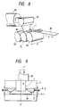
- Fig. 8 is a schematic perspective view of a molding machine having a roll stamper for forming an optical recording medium in accordance with this embodiment
- Fig. 9 is a diagram of an eccentric state of a molten resin sheet and the roll stamper in the apparatus shown in Fig. 8.
- a molten resin sheet 82 extruded from a T die 81 of an extruder 85 enters, in a molten or soft state, the gap between a specular roll 83 and a roll stamper 5, is then pressed and cooled, and is drawn in the direction of arrow Y out of the gap between the roll stamper 5 and the specular roll 84. Simultaneously, a pre-format pattern 4 formed in the surface of the flexible stamper 1 is accurately transferred to the molten resin sheet 82.
- the pressing screw at the end of the stamper in the direction opposite to the direction of the eccentricity f i.e., the right pressing screw 8-2 is unscrewed to the extent corresponding to the eccentricity.
- the left pressing screw 8-2 is thereafter made to advance to the extent corresponding to the eccentricity f to finely move the fixation member 3b in the direction opposite to the direction of the eccentricity, i.e., the direction of arrow Z to the extent corresponding to the eccentricity f and to simultaneously slide the other fixation member 3a to the same extent.
- centering adjustment can easily be effected.
- Fig. 6B and Fig. 6C which is a cross-sectional view taken along the line GG′ of Fig. 6B, so that the fixation member 3b is movable in the widthwise direction of the roll base 2 (the direction of arrows X) in a state of being not completely fixed to the roll base 2, centering adjustment can easily be effected even in the case of an arrangement using screws 7a.
- the arrangement may also be such that in accordance with the third embodiment of the present invention a hollow member in which a magnet rod 71 is inserted is welded as a stamper fixation member 3b to the stamper 1, as shown in Fig. 7A. If such a stamper fixation member is used, it is possible to prevent the fixation member 3b from coming off the fit groove 9b without using screws 7 when the stamper 1 is tensed.
- the cavity in the hollow member can be formed by drilling, electrical discharge machining, plate bending or the like.
- the magnet rod may be formed of a material such as SmCo 5 , Nd 2 Fe14B, Sm(Co, Fe, Cu) 6.8 or Sm(Co, Fe, Cu, Zr) 7.4 , or an Nd-Fe-B magnet.
- the cavity of the hollow member and the magnet rod may have a shape selected from those shown in Figs. 7B to 7D but not limited to these shapes.
- Centering adjustment can also be effected easily in this embodiment.
- Fig. 10A is a schematic plan view of a roll base 2 in which a fit groove 9b is formed
- Fig. 10B is a diagram of a roll stamper 5 manufactured by using this roll base.
- both end portions of a side 101 of the fit groove 9b facing the direction in which the flexible stamper is tensed are formed as tapered portions 101a, while wedges 106 worked to have opposite tapered surfaces such as to be capable of abutting on both tapered surfaces 3b-10 of a fixation member 3b and the surfaces of the tapered portions 101a of the fit groove 9b are prepared.
- These wedges 106 are disposed between the fixation member 3b and the side 101 of the fit groove 9b and are pressed with pressing screws 8-2 to apply a tensile force to the stamper 1.
- the angle ⁇ of the tapered portions 101a formed on the side 101 of the fit groove 9b is preferably 8 to 45°, more preferably, 10 to 40°
- the angle ⁇ of the tapered surfaces 3b-10 of the fixation member 3b is preferably 8 to 45°, more preferably, 10 to 40°.
- the angles ⁇ and ⁇ may be equal or different.
- the proportion of the length of the tapered portions 101a to half the length of the fixation member 3b (length 46) is set to preferably 1/3 or greater, more preferably 1/2 or greater as in the case of the first embodiment.
- the arrangement may be such that the tip of each wedge 6 may be inserted toward the center axis line C of the fixation member 3b by 1/6 or greater, more specifically, 1/4 or greater from the left or right end of the fixation member 3b, while the wedges 6 are formed so that at least 1/4, more specifically, at least 1/3 of each tapered surface 3b-10 of the fixation member 3b and each of tapered surfaces 101-10 of the side 101 of the fit groove 9b may be brought into contacts with the tapered surface 6-10 of the wedge 6 as described above. It is thereby possible to uniformly apply the force to the fixation member 3b in the direction toward the bottom of Fig. 4A or 4B to prevent deflection of the fixation member 3b. Consequently, it is possible to prevent the stamper 1 from floating from the roll base 2 in the vicinity of the center axis line C of the stamper 1 (and in the vicinity of the fixation member 3b in particular).
- Fig. 11A shows the fifth embodiment of the present invention which is characterized in that each of wedges 116 shown in Fig. 11A has a projection 111a at its tip and a notch 111b formed at the rear end of the projection 111a.
- the height h111a of the wedge projection 111a shown in Fig. 11B is formed so that the projection 111a may be located in the vicinity of the fixation member 3b when the wedges 116 are placed between fixation member 3b and the side 101 of the fit groove 9b without application of tensile force.
- the vicinity of the center of the fixation member 3b is meant throughout the description by a section defined between left and right ends of the fixation member 3b, having a distance of 1/6 or more, or more preferably 1/4 or more of the entire length of the fixation member 3b from each end toward the axial line C.
- the projection 111a can surely be brought into contact with the fixation member 3b in the vicinity of the center thereof to prevent the fixation member 3b from deflecting.
- the relationship between the length l 3b of the fixation member 3b and the width l 1 of the stamper shown in Fig. 15 is selected so that l 1 /l 3b is preferably 0.65 or smaller, more preferably, 0.59 or smaller, in terms of adhesion of the stamper 1 to the roll base.
- the arrangement may be such that the tip of each wedge 6 is not brought to a position under the stamper 1 in the state of application of tensile force. In this case, even if the tip of each wedge 6 is floated by the application of a pressing force to the wedge, the tip of the wedge does not interfere with the stamper 1 and there is no possibility of any bad influence upon the formation of a resin sheet.
- each wedge 6 can move to a position under the stamper 1
- the wedges 6 of the type shown in Fig. 11B are formed so as to have a cross-sectional shape, for example, such as to be reduced in thickness toward the projection 111a at the tip, as shown in Fig. 11C, thereby avoiding interference between the tip of each wedge 6 and the stamper 1.
- any method can be used as a method of fixing the fixation members 3a and 3b formed integrally with the stamper 1 so long as there is no possibility of the stamper 1 and the fixation members 3a and 3b separating from each other at the time of attachment of the stamper 1 to the roll base 2 and during and after resin sheet molding.
- electron beam welding, silver soldering, laser welding or the like is preferred if the strength of adhesion between the stamper and the fixation members and the evenness of the surface of the stamper are considered.
- fixation members 3a and 3b are placed in predetermined positions on a welding jig 122 having beam slits 121 as shown in Fig.
- stamper 1 a surface to be welded of lengthwise flexible stamper 1 (a surface opposite to another surface in which a pre-format pattern including tracking grooves and information pits is formed) and surfaces to be welded of fixation members 3a and 3b are brought into abutment on each other.
- An upper cover 123 is then placed on these members and fixed with screws, thereby completing setting.
- the stamper 1 is thereafter irradiated with an electron beam or a laser beam (e.g., YAG laser beam) through the slits 121, thereby fixing the fixation members to the stamper 1.
- a laser beam e.g., YAG laser beam
- the welding using an electron beam or a laser beam is performed by emitting pulses of the beams (having a frequency of, e.g., 60 Hz and a duty ratio of about 20 to 50 %), occurrence of strains in the flexible stamper can be markedly limited.
- stamper fixation members 3a and 3b In a process of fixing the stamper fixation members by silver soldering, a silver solder foil is placed between a surface to be welded of lengthwise flexible stamper 1 and surfaces to be welded of stamper fixation members 3a and 3b, and the surfaces to be welded are brought into abutment on each other. Stamper 1 and fixation members 3a and 3b are then pressed at a pressure of 20 to 50 kg/cm 2 so as to come into closely contact to each other. These members are then heated in a vacuum heating furnace under conditions: a vacuum of 2 x 10 ⁇ 5 Torr, a peak heating temperature of 820°C, and heating time of 7 hours to effect silver solder welding, thereby fixing the stamper fixation members to the lengthwise flexible stamper.
- Welding positioning can be effected with improved accuracy by performing welding after setting the stamper fixation members 3a and 3b in the grooves of the roll base 2.
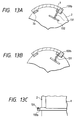
- Figs. 13A, 13B, 13C and 14 show the sixth embodiment of the present invention in which a different tensile force application means is used.
- a tension rod 131 is engaged at its one end with a fixation member 133b fixed to one end of the stamper 1 and is connected at the other end to a side portion of a roll base 2.
- the tension rod 131 is formed of a shape memory alloy whose predetermined shaped is restored when the temperature of the roll stamper is increased to a set temperature during resin molding, a bimetal which deforms at a set temperature, or the like. As the tension rod 131 is restored or deformed into a shape such as shown in Fig. 13B at the set temperature, a tensile force is applied to the stamper 1.
- Au-Cd alloy, Cu-Al-Zn alloy, Cu-Al-Ni alloy, In-Tl alloy, Ni-Al alloy, Ni-Ti alloy and the like are known as ordinary shape memory alloys, and any material can be used as the material of the tension rod 131 so long as it is capable of restoring the shape at a temperature close to the set temperature of the roll stamper. Specifically, a Ni-Ti alloy is preferred in terms of life during repeated use.
- a bimetal consisting of a combination of brass (30 to 40 % Zn) and nickel steel (34 % Ni), brass (30 to 40 % Zn) and invar (36 % Ni), Monel metal (Ni-Cu) and nickel steel (34 to 42 % Ni), or the like can be used.
- the side portion to which the other end of the tension rod is fixed may be formed so that the tension rod can slide, as indicated at 132 in Fig. 13A, thereby making it possible to accurately control the tensile force applied to the stamper 1.
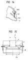
- Fig. 14 shows the seventh embodiment of the present invention in which a spring 141 is used as a means for applying a tensile force to the stamper 1.
- One end of the spring 141 is fixed to a fixation member 143b fixed to the stamper 1, while the other end of the spring 141 is fixed to a side portion of the roll base 2.
- a sliding portion 142 is formed as the spring fixation side portion of the roll base 2 so that the other end of the spring 141 can slide. It is possible to control the tensile force applied to the stamper 1 by changing the position at which the other end of the spring is fixed.
- This embodiment in which a spring is used as a tensile force application means, is advantageous because even if an overload is imposed upon the stamper 1, for example, by adhesion of the molten resin during molding, the resiliency of the spring prevents the stamper 1 from being easily damaged.
- the arrangement of the present invention may alternatively be such that fixation members 3b,.133b or 143b are fixed to both end portions of the reverse surface of the flexible stamper 1, and tensile force application means are disposed in association with these two fixation members 3b to pull the two ends of the flexible stamper 1 in opposite directions.
- the two tensile force application means may be the same or different.
- the flexible stamper 1 in accordance with the present invention is manufactured by an ordinary process, e.g., an electroforming process.
- the thickness of the stamper 1 is set to, preferably, a value in the range of 20 to 500 ⁇ m in consideration of sufficient never and inhibition of increase in the diameter of the roll stamper.
- Information recording pre-format pattern 4 to be formed in the stamper in accordance with the present invention is, for example, a pattern corresponding to a spiral groove, concentric-circle grooves or parallel grooves for optical disks or optical cards having a width of 1.5 to 2 ⁇ m, a pitch of 1.0 to 5 ⁇ m and a depth of about 200 to 5,000 ⁇ , or a pattern corresponding to a spiral groove, concentric-circle grooves or parallel grooves for optical disks or optical cards having a width of 2 to 5 ⁇ m, a pitch of 8 to 15 ⁇ m and a depth of about 200 to 5,000 ⁇ .
- the reverse surface of the stamper more specifically, a portion of the reverse surface corresponding to an obverse surface region in which pre-format pattern 4 is formed is polished so as to be specular, i.e., to have a surface roughness of 0.1 ⁇ m or lower.
- the circumferential surface of the roll base 2 used in accordance with the present invention is polished to have a surface roughness of 0.1 ⁇ m or lower.
- a material which can be polished to form a specular surface e.g., carbon steel, Al, a sintered hard metal, or die steel (such as marageing steel)
- chromium steel which can easily be posished to form a specular surface is preferably used.
- the roll base 2 may have an inner cavity through which a heating medium for heating the roll stamper, e.g., oil or the like, can be circulated.
- a heating medium for heating the roll stamper e.g., oil or the like
- the thickness of the roll base 2 is preferably in the range of 10 to 15 cm if the strength of the roll stamper and limiting the diameter of the roll stamper are considered.
- Fit grooves 9a and 9b can be formed in the roll base 2 by electrical discharge machining, bite machining, dressing or the like.
- resin pellets thrown into an extruder 85 are heated and melted in a barrel of extruder 85, pressurized by a screw, and formed into a sheet-like shape by T-die 81.
- the temperature of the resin in this step is, for example, 260 to 330°C, more preferably, 280 to 320°C in the case of a polycarbonate resin.
- a transparent resin sheet 82 in a substantially molten state is thereby extruded continuously from the T-die.
- the T-die is positioned so that the molten resin sheet is extruded into between specular roll 83 and roll stamper 5.
- the molten resin sheet is pinched between roll stamper 5 and specular roll 83 and between roll stamper 5 and specular roll 84 to transfer pre-format pattern 4 on the surface of the flexible stamper 1, thereby forming an information recording medium substrate sheet 86.
- the roll stamper 5 in accordance with the present invention is maintained at a temperature such that the molten resin sheet is not solidified on the roll stamper. That is, it is preferable to heat the roll stamper up to the range of + 20 to - 20°C, about the thermal deformation temperature of the resin. For example, if a poly-carbonate resin is used, it is preferable to heat the surface temperature of the roll stamper to the range of 100 to 160°C. That is, in this temperature range, the molten resin sheet is not abruptly cooled, so that strain due to shrinkage or the like is not easily caused in the resin sheet. It is also preferable to set the temperature of the specular rolls 83 and 84 facing the roll stamper 5 to the same temperature as that of the roll stamper 5 or a slightly lower temperature.
- the temperatures of these rolls are controlled, for example, by electrical heating through a cast heater in the rolls or by circulating a heating medium through central portions of the rolls.
- a roll stamper having improved durability can be obtained in which the flexible stamper is not separated from the roll base even during the process of continuously transferring a pre-format pattern to a resin sheet.
- the flexible stamper can be fixed with improved adhesion on the circumferential surface of the roll base so that occurrence of a gap between the flexible stamper and the roll base is inhibited. Consequently, during the process of forming a resin sheet, the heat conducted to the flexible stamper can be rapidly transmitted to the roll base so that the temperature of the whole surface of the flexible stamper on the roll base is uniform. It is thereby possible to obtain, with improved productivity, a high-quality information recording medium substrate improved in pre-format transfer performance, free of transfer failure and birefringence.
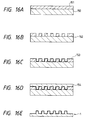
- a flexible stamper 1 was manufactured by a process described below. First, a surface of a blue plate glass having a length of 34 cm, a width of 30 cm and a thickness of 10 mm was polished to be specular, and a 3,000 ⁇ photoresist layer of a photoresist (commercial name: AZ-1370, a product from Nippon Hoechst Co., Ltd.) was formed on the polished surface and was pre-baked at 90°C for 30 minutes (Fig. 16A).
- a photoresist layer of a photoresist commercial name: AZ-1370, a product from Nippon Hoechst Co., Ltd.
- a resist pattern was formed by exposure of a pre-format pattern for an optical card with a laser exposure apparatus and a developer liquid (commercial name: AZ312MIF, a product from Nippon Hoechst Co., Ltd.), thereby forming an glass original plate 152 for forming optical cards (Fig. 16B).
- a developer liquid commercial name: AZ312MIF, a product from Nippon Hoechst Co., Ltd.
- the pre-format pattern has a pattern corresponding to optical card grooves formed in an area of 80 x 30 mm and having a width of 2.5 ⁇ m, a pitch of 9.5 ⁇ m, and a depth of 2,500 - 3,000 ⁇ .
- the same pre-format patterns corresponding to 9 optical cards were formed on one glass original plate.
- a nickel film having a thickness of 1,000 to 2,000 ⁇ was formed by a sputtering apparatus as an electroconductive layer 153 on the glass original plate 152 (Fig. 16C).
- a metallic film 154 of nickel having a thickness of 250 ⁇ m was formed by electroforming on the electroconductive film 153 formed on the glass original plate 152 (Fig. 16D).
- the electroconductive layer 153 and the metallic film 154 were separated as one united member from the glass original plate 152 and the photoresist attached to the obverse surface was removed. Then the reverse surface was worked by trimming and was polished to form a specular surface having a surface roughness of 0.1 ⁇ m, thereby manufacturing a lengthwise flexible stamper 1 such as shown in Fig. 1B having 9 optical card pre-format patterns on in the obverse surface and having a length of 293 mm, a width of 150 mm and a thickness of 200 ⁇ m (Fig. 16E). Fixation members 3a and 3b were fixed to both end portions of the reverse surface of the thus-obtained stamper 1.
- fixation member 3a was of stainless steel having a length of 310 mm, a width of 13 mm and a height of 10 mm.
- Fixation member 3b was a member which had a cross-sectional shape such as shown in Fig. 3B having a height (h) of 10 mm and a width (W) of 18.5 mm, and a shape as viewed in plan in which a length was 310 mm the angle ⁇ of tapered portions 3b-10 was 13.5° and the length 44 of the tapered portions was 77.5 mm.
- This fixation member was formed of stainless steel (SUS 430) having a Young's modulus of 1.97 x 10 4 kg/mm 2 .
- the distance 47 between fixation members 3a and 3b as shown in Fig. 6 was set to 283 mm.
- Stamper 1 and fixation members 3a and 3b were fixed to each other by electron beam welding, that is, they were welded with a welding jig 122 such as shown in Fig. 12 and an electron beam welding machine (commercial name: EBW6LB, a product from Mitsubishi Electric Corp.).
- the welding was performed under conditions: a vacuum of 5 x 10 ⁇ 2 Torr, acceleration voltage of 60 kV, a beam current of 3.2 mA, a beam speed of 4.0 m/min.
- the circumferential surface of a roll base formed of stainless steel was plated with chromium and was polished to form a specular surface having a surface roughness of 0.1 ⁇ m or lower, thereby forming a roll base 2 having a diameter of 310 mm and a width of 500 mm.
- a groove having a depth of 10 mm, a width of 13.1 mm and a length of 500 mm was formed as fit groove 9a
- another groove having a depth (d) of 10 mm, a width (W 9b ) of 20.5 mm and a length of 500 mm was formed as fit groove 9b shown in Fig. 3.
- the distance 48 between fit frooves 9a and 9b as shown in Fig. 6 was set to 292.5 mm.
- Fixation members 3a and 3b are fitted in fit grooves 9a and 9b and were temporarily fixed with screws 7a to an extent such that stamper 1 was movable. In this state, the clearance 43 as shown in Fig. 5 was 1.5 mm.
- wedges 6 fixed members 8-1 and pressing screws 8-2 constituting a tensile force application means were then disposed as shown in Fig. 2, and the pressing screws were made to advance to press wedges 6, thereby applying a tensile force of 5 kgf/mm 2 to stamper 1.
- wedges 6 stainless steel members in which the tapered portions had an angle ⁇ ′ of 12.8°, a length 45 of 39 mm, a height of 10 mm and a width of 18.5 mm, was used.
- screws 7 were fastened to firmly fix the fixation members 3b to roll base 2, manufacturing a roll stamper.
- This roll stamper was attached to a molding machine such as shown in Fig. 8, and a polycarbonate resin was extruded from extruder 85, thereby manufacturing an optical card substrate sheet having a thickness of 0.4 mm.
- the molding was condinuously performed for 10 hours under conditions: a T-die temperature of 300°C, a roll stamper 5 surface temperature of 145°C, and a resin sheet transport sheet of 3 m/min.
- the birefringence of the optical card substrate sheet thereby formed was as small as 10 to 15 nm and the performance of transferring the pre-format pattern was high.
- the surface temperature of flexible stamper 1 of roll stamper 5 immediately after the molding was measured with an infrared radiation thermometer (commercial name: Thermal video system TVS-5000, a product from Nippon Avionics Co. Ltd.) to observe temperature unevenness at the surface of stamper 1.
- an infrared radiation thermometer commercial name: Thermal video system TVS-5000, a product from Nippon Avionics Co. Ltd.
- the temperature difference was as small as at most 10°C and the proportion of a region where a temperature unevenness occurred to the surface area of stamper 1 was only about 5%. It was thereby understood that the adhesion between roll base 2 and flexible stamper 1 was good even during molding.
- Roll stampers 5 were manufactured and optical card substrate sheets were formed in the same manner as Example 1 except that the tensile force applied to the flexible stamper was changed as shown in Table 1 shown below. Surface temperature unevenness and the proportion of a region on flexible stamper 1 of roll stamper where temperature unevenness occurred to the surface area of flexible stamper 1 (area ratio) immediately after continuous molding for 10 hours, were evaluated in the same manner as in Example 1. The result of this evaluation is shown in Table 1.
- Roll stampers 5 were manufactured and optical card substrate sheets were formed in the same manner as Example 1 except that the tensile force applied to the flexible stamper was changed as shown in Table 2 shown below.
- Table 2 The surface temperature and the proportion of a region on flexible stamper 1 of roll stamper 5 where temperature unevenness occurred to the surface area of flexible stamper 1 (area ratio) immediately after continuous molding for 10 hours, were measured and evaluated. The result of this evaluation is shown in Table 2(1).
- a roll stamper was manufactured and evaluated in the same manner as Example 1 except that the length (44) of tapered portions 3b-10 of fixation member 3b was set to 45 mm. The result of the evaluation is shown in Table 2(2).
- a lengthwise flexible stamper 1 having a length of 293 mm, a width of 37.7 mm and a thickness of 200 ⁇ m and having three optical card pre-format patterns on its obverse surface was manufactured in the same manner as in Example 1.
- Fixation members 3a and 3b were fixed to both end portions of the reverse surface of the thus-obtained stamper 1.
- fixation member 3a was used a stainless steel member having a length of 65 mm, a width of 13 mm and a height of 10 mm.
- Fixation member 3b was a member which had a cross-sectional shape such as shown in Fig. 3B having a height (h) of 10 mm and a width (W) of 18.5 mm, and a shape as viewed in plain having a length of 65 mm, the angle of ⁇ of tapered portions 3b-10 of 10° and the length 44 of the tapered portions of 11 mm, and which was formed of stainless steel (SUS 430).
- Fixation members 3a and 3b were fixed to stamper 1 as shown in Fig. 6 by laser beam welding, that is, they were welded with a welding jig 122 such as shown in Fig. 12 and a YAG laser welding machine (commercial name: ML-2220A, a product from Miyaji Laser System K.K.) under conditions: a changing voltage of 350 V, a pulse width of 1.0 ms, an extent of defocus of 5 mm, a REP-RATE (PPS) of 20, and power of 35 to 65 W.
- a welding jig 122 such as shown in Fig. 12
- a YAG laser welding machine commercial name: ML-2220A, a product from Miyaji Laser System K.K.
- the circumferential surface of a roll base formed of stainless steel was plated with chromium and was polished to form a specular surface having a surface roughness of 0.1 ⁇ m or lower, thereby forming a roll base 2 having a diameter of 310 mm and a width of 500 mm.
- a groove having a depth of 10 mm, a width of 13.1 mm and a length of 500 mm was formed as fit groove 9a
- another groove having a depth (d) of 10 mm, a width (W′) of 20 mm and a length of 500 mm was formed as fit groove 9b shown in Fig. 3.
- the distance 48 between fit grooves 9a and 9b as shown in Fig. 6 was set to 292.5 mm.
- Fixation members 3a and 3b were fitted in fit grooves 9a and 9b and were temporarily fixed with screws 7a to an extent such that stamper 1 was movable. In this state, the clearance 43 as shown in Fig. 5 was 1.5 mm.
- wedges 6 fixed members 8-1 and pressing screws 8-2 constituting a tensile force application means were then disposed as shown in Fig. 2, and the pressing screws were made to advance to press wedges 6, thereby applying a tensile force of 10 kgf/mm 2 to stamper 1.
- wedges 6 stainless steel members in which the tapered portions had an angle ⁇ ′ of 9.5°, a length 45 of 6 mm, a height of 10 mm and a width of 18.5 mm was used.
- screws 7 were fastened to firmly fix the fixation members 3b to roll base 2, thus manufacturing a roll stamper.
- This roll stamper was attached to a molding machine such as shown in Fig. 8, and a polycarbonate resin was extruded from extruder 85, thereby manufacturing an optical card substrate sheet having a thickness of 0.4 mm.
- the molding was continuously performed for 10 hours under conditions: a T-die temperature of 300°C, a roll stamper 5 surface temperature of 145°C, and a resin sheet transport speed of 3 m/min.
- the birefringence of the optical card substrate sheet thereby formed was as small as 10 to 15 nm and the performance of transferring the pre-format pattern was high.
- the surface temperature of flexible stamper 1 of roll stamper 5 immediately after the molding was measured with an infrared radiation thermometer (commercial name: Thermal Video System TVS-5000, a product from Nippon Avionics Co., Ltd.) to observe temperature unevenness at the surface of stamper 1.
- an infrared radiation thermometer commercial name: Thermal Video System TVS-5000, a product from Nippon Avionics Co., Ltd.
- the temperature difference was as small as at most 10°C and the proportion of a region where a temperature unevenness occurred to the surface area of stamper 1 was only about 5 %. It was thereby understood that the adhesion between roll base 2 and flexible stamper 1 was good even during molding.
- a roll base 2 having a diameter of 310 mm and a width of 500 mm was formed by plating the circumferential surface of a stainless steel roll member with chromium and by finishing this surface as a specular surface having a surface roughness of 0.1 ⁇ m or lower.
- a groove having a depth of 10 mm, a width of 13.1 mm and a length of 500 mm was formed as a fit groove 9a in the circumferential surface of the roll base.
- the distance 48 between fit grooves 9a and 9b as shown in Fig. 6 was set to 292.5 mm.
- Fixation members 3a and 3b were fitted in fit grooves 9a and 9b and were temporarily fixed with screws 7a to an extent such that stamper 1 was movable. In this state, the clearance 43 as shown in Fig. 5 was 1.5 mm.
- wedges 6 fixed members 8-1 and pressing screws 8-2 constituting a tensile force application means were then disposed as shown in Fig. 10B, and the pressing screws were made to advance to press wedges 6, thereby applying tensile forces of 5kgf/mm 2 and 20 kgf/mm 2 to stamper 1.
- wedges 6 wedges having a shape such as shown in Fig. 11B were used.
- Each wedge 116 has a length (l116) of 150 mm, the height (h 111a ) of the tip projection was 1 mm, the depth of the notch (111b) was 0.5 mm, and both the angles ⁇ ′ and ⁇ ′ were 12.8°.
- Each wedge 116 was tapered to have a height of 10 mm at its rear end and a height of 6 mm at its tip (see Fig. 11C).
Abstract
Description
- This invention relates to a roll stamper used to continuously manufacture a substrate for a high-density information recording medium such as an optical disk or optical card by transferring a pre-format pattern to a substrate surface, and to an apparatus for forming the high-density information recording medium substrate by using the stamper.
- For example, an injection molding method, a compression molding method and an extrusion molding method are known as methods for manufacturing the substrate for a high-density optical recording medium such as an optical disk or optical card.
- When the injection molding method or compression method is used, strict conditions are set with respect to the temperature and the pressure of a molten resin and the precision of dies and so on to achieve the desired flatness and smoothness of the substrate, to limit a warp of the substrate and to prevent inclusion of air bubbles in the molten resin, and a large-scale molding machine is therefore required, resulting in an increase in manufacturing cost. In the case of injection molding, it is difficult to manufacture a substrate having a small thickness of 0.4 mm or less and a small double refraction index. In the case of compression molding and injection molding, the productivity is low because molded sheets are separately formed one after another.
- An information recording medium substrate may be manufactured by extrusion molding in such a manner that a sheet of a molten resin extruded from an extruder is pressed by a roll stamper to form the substrate while transferring a pre-format pattern for providing a pre-format signal, a tracking signal and the like. Such an extrusion molding process is therefore advantageous in terms of mass production of a substrate and has recently been studying as a method for forming an information recording medium substrate.
- Roll stampers to be used to form an information recording medium substrate by extrusion molding as described above have conventionally been manufactured by the following methods:
- (1) a method in which a pre-format pattern is directly formed in a circumferential surface of a roll base having the circumferential surface polished to form a specular surface (hereinafter referred to as "specular roll base");
- (2) a method in which a flexible stamper having a pre-format pattern previously formed on its surface is uniformly bonded to a specular circumferential surface of a specular roll with an adhesive; and
- (3) a method in which a flexible stamper having a pre-format pattern previously formed on its surface is fixed to a specular circumferential surface of a specular roll with screws.
- In the case of the method (1), if a defect is caused in only one portion of the pre-format pattern, the whole roll stamper must be exchanged, and the molding efficiency is therefore low. In the roll stamper manufactured by the method (2), the adhesive is changed in quality with time by the heat of the extruded resin sheet or the heat of the roll so that the bonding force is reduced and the stamper may easily come off the specular roll. Therefore the life of the roll stamper is very short. Moreover, air bubbles are liable to be generated in the adhesive. Unnecessary irregularities in the stamper surface caused by the air bubbles are transferred to the substrate, so that the pattern may not be formed accurately and there is a problem of resulting in transfer failure. In the case of the roll stamper manufactured by the method (3), it is difficult to limit the gap between the flexible stamper and the roll base, and therefore non-uniformity of the temperature on the stamper surface tends to occur, thereby resulting in molding failure. A method is therefore needed which enables a flexible stamper to be securely fixed on a specular roll base so that the stamper surface (reverse surface) on which no pre-format pattern is formed is brought into close contact with the circumferential surface of the specular roll base while occurrence of a strain in the stamper is prevented.
- The present invention has been achieved in view of the above-described conventional related art, and an object of the present invention is to provide a roll stamper used to form an information-recording medium substrate, fixed accurately and securely on a specular roll surface, having a long life, and capable of transferring only a pre-format pattern onto a resin sheet with accuracy.
- Another object of the present invention is to provide an apparatus for manufacturing an information recording medium substrate which apparatus enables a pre-format pattern to be transferred onto a resin sheet with accuracy while preventing occurrence of birefringence in the resin sheet.
- Still another object of the present invention is to provide a method of manufacturing an information recording medium substrate in which a pre-format pattern can be transferred onto a resin sheet with accuracy while occurrence of birefringence in the resin sheet is prevented.
- According to one aspect of the present invention, there is provided a roll stamper for forming an information recording medium substrate, comprising a stamper member having a pattern corresponding to a pre-format for an information recording medium formed on its obverse surface, fixation members fixed to both end portions of a reverse surface of the stamper so as to be integral with the stamper member, and fit grooves capable of fittingly receiving the fixation members and formed on a circumferential surface of a specular roll base parallel to the axis of the specular roll base, the fixation members being fitted in the fit grooves, the stamper member being fixed along the circumferential surface of the specular roll base, and means for applying a tensile force to the stamper member.
- According to another aspect of the present invention, there is provided an apparatus for continuously manufacturing an information recording medium substrate, comprising means for melting and extruding a resin to form a resin sheet, a roll stamper having a pattern corresponding to a pre-format formed on its surface, and a specular roll disposed so as to face the roll stamper, the roll stamper comprising a stamper member having a pattern corresponding to a pre-format pattern for an information recording medium, fixation members fixed to both end portions of a reverse surface of the stamper so as to be integral with the stamper member, fit grooves capable of fittingly receiving the fixation members and formed in a circumferential surface of a specular roll base parallel to the axis of the specular roll base, the fixation members being fitted in the fit grooves, the stamper member being fixed along the circumferential surface of the specular roll base, and means for applying a tensile force to the stamper member.
-
- Fig. 1 is a perspective view of a roll stamper in accordance with a first embodiment of the present invention;
- Fig. 2 is an enlarged plan view of a protion in the vicinity of a fixation member of the roll stamper shown in Fig. 1;
- Fig. 3 is a cross-sectional view taken along the line A-A′ of Fig. 2;
- Fig. 4A is a diagram of an essential portion of the roll stamper shown in Fig. 1;
- Fig. 4B is a diagram of the shapes of the fixation member and wedges of the roll stamper shown in Fig. 1;
- Fig. 5 is an exploded sectional view of the roll stamper shown in Fig. 1;
- Fig. 6A is a schematic cross-sectional view of a roll stamper in accordance with a second embodiment of the present invention;
- Fig. 6B is a schematic plan view of the roll stamper shown in Fig. 6A;
- Fig. 6C is a cross-sectional view taken along the line G-G′ of Fig. 6B;
- Fig. 7A is a schematic cross-sectional view of a roll stamper in accordance with a third embodiment of the present invention;
- Fig. 7B is a diagram of an example of an inner cavity of the fixation member;
- Fig. 7C is a diagram of another example of the inner cavity of the fixation member;
- Fig. 7D is a diagram of still another example of the inner cavity of the fixation member;
- Fig. 8 is a schematic diagram of an apparatus for manufacturing an information recording medium substrate in accordance with the present invention;
- Fig. 9 is a diagram of centering adjustment of a molten resin sheet and the roll stamper;
- Fig. 10A is a schematic plan view of a roll base for use in a roll stamper in accordance with a fourth embodiment of the present invention;
- Fig. 10B is a schematic plan view of the roll stamper using the roll base shown in Fig. 10A in accordance with the fourth embodiment;
- Fig. 11A is a schematic plan view of a roll stamper in accordance with a fifth embodiment of the present invention;
- Fig. 11B is a plan view of the wedge for use in the roll stamper shown in Fig. 11A;
- Fig. 11C is a cross-sectional view of the wedge taken along the line H-H′ of Fig. 11B;
- Fig. 12 is a diagram of a method of welding the flexible stamper and the fixation member;
- Figs. 13A to 13C are schematic diagrams of a roll stamper in accordance with a sixth embodiment of the present invention;
- Fig. 13A is a schematic cross-sectional view of a state before a tensile force is applied to the stamper;
- Fig. 13B is a schematic cross-sectional view of a state after the tensile force has been applied to the stamper;
- Fig. 13C is a schematic plan view of the roll stamper shown in Fig. 13A;
- Fig. 14 is a schematic cross-sectional view of a roll stamper in accordance with a seventh embodiment of the present invention;
- Fig. 15 is a diagram of the relationship between the widths of the fixation member and the stamper; and
- Fig. 16A to 16E are diagrams of the steps of a process for manufacturing the stamper.
- The present invention will be described below in detail with reference to the accompanying drawings.
- Fig. 1 is a perspective view of a
roll stamper 5 in accordance with an embodiment of the present invention. Theroll stamper 5 is composed of a lengthwiseflexible stamper 1 having an opticalcard pre-format pattern 4 formed on its surface, aspecular roll base 2 on which the lengthwiseflexible stamper 1 is fixed,stamper fixation members stamper 1 on theroll base 2,wedges 6 constituting a means for applying a tensile force to thestamper 1, and other members. In this embodiment, the tensile force application means is constituted of, as shown in Fig. 2, thewedges 6, and pressure application means 8 (fixing members 8-1 and pressing screws 8-2) for applying a pressing force to thewedges 6 in a direction toward a center axis line C of the roll stamper. Fig. 2 is an enlarged plan view of a portion of theroll stamper 5 in the vicinity of thestamper fixation member 3b shown in Fig. 1. (For simplification, the pressure application means 8 is omitted in Fig. 1.) - The tensile force application means of this embodiment will be described below in more detail with reference to Fig. 2.
- The fixed members 8-1 are fixed on side surfaces of the
roll base 2 so as to cover both ends of afit groove 9b formed in the circumferential surface of theroll base 2. The pressing screws 8-2 are each screwed through the fixed members 8-1. The tip of each pressing screw 8-2 is formed so as to be capable of abutting against and pressing thewedge 6 as the pressing screw is advanced. Thefixation member 3b has taperedsurfaces 3b-10 which are brought into contact with tapered surfaces of thewedges 6 and which function to cause a force for tensing thestamper 1 from a pressure which is applied to thewedges 6 by the advancing movement of the pressing screws.Screws 7a are used to fix thefixation member 3b on theroll base 2. - Referring back to Fig. 1, the
roll stamper 5 will be further described below. Thestamper fixation members roll base 2 and are integrally fixed to both end portions of the reverse surface of thestamper 1.Fit grooves fixation members specular roll base 2 so as to extend along the axis of thespecular roll 2. The sectional configuration of thefit groove 9a is generally equal to the sectional configuration of thefixation member 3a. Thefixation member 3a is fitted in thefit groove 9a to fix one end of thestamper 1 to theroll base 2 substantially firmly. Thefit groove 9b is formed so as to have a width W9b greater than the width W3b of thefixation member 3b so that thefixation member 3b can move in thefit groove 9b when a tensile force is applied to thestamper 1 after thefixation member 3b has been fitted in thefit groove 9b by the above-described tensile force application means (6 and 8). - As shown in Fig. 2 and Fig. 3 which is taken along the line A-A′ of Fig. 2, holes 7B which are formed in the
fixation member 3b and through which thescrews 7a for fixing thefixation member 3b to theroll base 2 are passed are elongated so that thefixation member 3b can move in the lengthwise direction of the stamper 1 (in the direction B shown in Figs. 2 and 3) when thefixation member 3b is not completely fixed to theroll base 2. Hole 7B edges are chamferred so that the heads of thescrews 7a may not protrude from the roll stamper surface. - The
roll stamper 5 in accordance with this embodiment is assembled as described below. First, the£ fixation members stamper 1 are each fitted in thefit grooves specular roll base 2, and thefixation member 3b is temporarily fixed to theroll base 2 with thescrews 7a to an extent such as to be able to move in the direction B. - Next, as shown in Fig. 2, the
wedges 6 are placed so that its tapered surfaces 6-10 may come into contact with thetapered surfaces 3b-10 of thefixation member 3b, and its surfaces opposite to the tapered surfaces may come into contact with a wall surface of thefit groove 9b. The pressing screws 8-2 which are screwed into the fixing members 8-1 fixed on side surfaces of theroll base 2 so as to cover opposite ends of afit groove 9b, and abut against thewedges 6, are made to advance toward the center axis line C of theroll stamper 5. By this movement, a component of the pressing force applied to thewedges 6 acts as a force for tensing thestamper 1, and thestamper 1 is thereby brought into uniform and close contact with the circumferential surface of theroll base 2. Thestamper 1 is thereby firmly fixed to theroll base 2 with thescrews 7a. Theroll stamper 5 is thus obtained. - According to the present invention, if the tensile force applied to the
stamper 1 in the direction toward the bottom of Fig. 2 along the direction B is set to 5 to 40 kgf/mm2, more specifically 5 to 20 kgf/mm2, thestamper 1 can be brought into close contact with the circumferential surface of theroll base 2 without causing a strain in thestamper 1, and occurrence of a gap between thestamper 1 and theroll base 2 can be prevented when the stamper is used to form a resin sheet. It is thereby possible to obtain aroll stamper 5 which is capable of continuously transferring a pre-format pattern to a resin sheet with high accuracy, and improved in durability. - In the
roll stamper 5 in accordance with the above-described embodiment, as the material of thefixation member 3b having taperedsurfaces 3b-10 contacting thewedges 6, a material having a Young's modulus of, preferably, 7.4 x 10³ to 9 x 10⁴ kgf/mm2, more preferably, 1.8 x 10⁴ to 4 x 10⁴ kgf/mm2 is selected to limit the bending of both end portions of thefixation member 3b caused by the force applied in the direction toward the bottom of Fig. 2 along the direction B as a component of the pressing force from thewedges 6. For example, stainless steel (SUS430), a copper alloy, carbon steel, cast iron, aluminum alloy, ceramics and the like may be used as this fixation member material. The cross-sectional area of thefixation member 3b is set to, preferably, 330 to 600 mm2, more preferably, 80 to 250 mm2 for the same reason, that is, to limit the bending of the mixing member 3. - The depth of the
fit grooves roll base 2 in accordance with the present invention varies according to the thickness of theroll base 2, but it is set to, preferably, 3 to 20 mm, more preferably, 5 to 10 mm with respect to a hollow roll base having a thickness of 20 to 40 mm. That is, if the depth of the fit grooves is set within this range, there is no risk of a reduction in the strength of the roll base while suitable engagement between the roll base and the fixation member is ensured. Further, in this range, the change in the thermal capacity of theroll stamper 5 is limited to a comparatively small extent. - On the basis of the cross-sectional area of the
fixation member 3b and the depth of the fit grooves, the width W3b of the fixinggroove 3b is set to, preferably, 10 to 30 mm, more preferably, 16 to 25 mm. It is necessary to add at least aclearance 43 to the width of the fixingmember 3b to determine the width W9b of thefit groove 9b in which thefixation member 3b is fitted, as shown in Figs. 4A and 4B. Theclearance 43 is required to enable the application of the tensile force from thewedges 6 to thestamper 1 in the direction toward the bottom of Fig. 4A or 4B along the direction B of thefixation member 3b. Theclearance 43 may be set to 0.3 to 2 mm, more specifically, 0.5 to 1 mm to ensure the application of the tensile force to thestamper 1 while limiting the formation of an unnecessary recess in the circumferential surface of theroll stamper 5. Figs. 4A and 4B are schematic plan views of a portion of theroll stamper 5 in the vicinity of thefixation member 3b and the tensile force application means, Fig. 4A illustrating the related members, Fig. 4B showing the configurations of the members. - According to the present invention, if, as shown in Fig. 5 which is an exploded view of the
stamper 2 to which thefixation members roll base 2 in whichgrooves distance 47 between thefixation members distance 48 between thefit grooves clearance 43′ exists along the outer-end surface of thestamper 1 facing in the direction of application of the tensile force, as shown in Fig. 3, so that thermal capacity variations occurring in the roll stamper can be controlled in a small range. - The shapes of the
fixation member 3b and thewedges 6 in accordance with the present invention will be described below. As described above, thefixation member 3b has taperedsurfaces 3b-10 formed on both its end portions for abutment against the tapered surfaces 6-10 of thewedges 6. The angle ϑ between each tapered portion of thefixation member 3b and a line parallel to the longitudinal axis of the fixingmember 3b (direction X) (see Fig. 4B) is set to, preferably, 8 to 45°, more preferably, 10 to 40° to efficiently produce the tensile force of thestamper 1 from the pressing force from thewedges 6 while avoiding concentration of the tensile force to end portions of thefixation member 3b alone. - The angle ϑ′ of the tapered surface 6-10 of each
wedge 6 is set to be substantially equal to ϑ so that thetapered portions 3b-10 of thefixation member 3b and the tapered surfaces of thewedges 6 abut uniformly on each other.
wedges 6 and thefixation member 3b are formed so that the tapered surface of eachwedge 6, whose tapered portion 6-10 has alength 45, can always come into contact with 1/4 or greater, more specifically, 1/3 or greater of the tapered surface area of thefixation member 3b, there is no risk of a considerable concentration of tensile force to a particular portion of thefixation member 3b and, hence, no risk of occurrence of considerable strain in thefixation member 3b. - Also, the arrangement may be such that proportion of the
length 44 of the tapered portion of thefixation member 3b shown in Fig. 4B to 1/2 of the length of thefixation member 3b (length 46) is 1/3 or greater, more specifically, 1/2 or greater, and such that the tip of eachwedge 6 can be inserted toward the center axis line C of thefixation member 3b by 1/6 or greater, more specifically, 1/4 or greater from the left or right end of thefixation member 3b, while thewedges 6 are formed so that at least 1/4, more specifically, at least 1/3 of eachtapered surface 3b-10 of thefixation member 3b may be brought into contacts with the tapered surface 6-10 of thewedge 6 as described above. It is thereby possible to uniformly apply the force to thefixation member 3b in the direction toward the bottom of Fig. 4A or 4B to prevent deflection of thefixation member 3b. Consequently, it is possible to prevent thestamper 1 from floating from theroll base 2 in the vicinity of the center axis line C of the stamper 1 (and in the vicinity of thefixation member 3b in particular). - The material of the
wedges 6 in accordance with the present invention may be the same as the above-described material of thefixation member 3b. - In the second embodiment of the present invention, the
fit groove 9a formed in theroll base 2 and thefixation member 3a fitted in thefit groove 9a have cross-sectional shapes such as to be engageable with each other, e.g., trapezoidal shapes shown in Fig. 6A. By this arrangement, thefixation member 3a can be prevented from floating and coming off thefit groove 9a by the application of the tensile force from the tensile force application means to the stamper, even if thefixation member 3a and theroll base 2 are not fixed to each other with screws. - With respect to the cross-sectional shapes of the
fit groove 9b and thefixation member 3b as well, right end portions of thefixation member 3b and thefit groove 9b are formed by being tapered in the direction of their height (depth) as shown in Fig. 6A, thereby effectively preventing the fixinggroove 3b from coming off thefit groove 9b without using screws when the stamper is tensed. - By this arrangement, the need for fixing the fixation member to the roll base with screws is eliminated to enable the
stamper 1 to move in the axial direction of theroll base 2, thereby making it easy to effct centering adjustment, e.g., to make the center axis of thestamper 1 coincide with that of a molten resin sheet to be formed. - Fig. 8 is a schematic perspective view of a molding machine having a roll stamper for forming an optical recording medium in accordance with this embodiment, and Fig. 9 is a diagram of an eccentric state of a molten resin sheet and the roll stamper in the apparatus shown in Fig. 8.
- As shown in Fig. 8, a
molten resin sheet 82 extruded from a T die 81 of anextruder 85 enters, in a molten or soft state, the gap between aspecular roll 83 and aroll stamper 5, is then pressed and cooled, and is drawn in the direction of arrow Y out of the gap between theroll stamper 5 and thespecular roll 84. Simultaneously, apre-format pattern 4 formed in the surface of theflexible stamper 1 is accurately transferred to themolten resin sheet 82. If at this time an error in the positioning theroll stamper 5 occurs such that the center line DD′ of theflexible stamper 1 does not coincide with the center line EE′ of themolten resin sheet 82 and has an eccentricity f from the same as shown in Fig. 9, it is preferable to effect centering adjustment by making the center lines DD′ and EE′ coincide with each other. - In this embodiment, as shown in Fig. 9, the pressing screw at the end of the stamper in the direction opposite to the direction of the eccentricity f, i.e., the right pressing screw 8-2 is unscrewed to the extent corresponding to the eccentricity. The left pressing screw 8-2 is thereafter made to advance to the extent corresponding to the eccentricity f to finely move the
fixation member 3b in the direction opposite to the direction of the eccentricity, i.e., the direction of arrow Z to the extent corresponding to the eccentricity f and to simultaneously slide theother fixation member 3a to the same extent. Thus, centering adjustment can easily be effected. - If the
screws 7a and theholes 7b for fixing thefixation member 3b to theroll base 2 are formed, as shown in Fig. 6B and Fig. 6C which is a cross-sectional view taken along the line GG′ of Fig. 6B, so that thefixation member 3b is movable in the widthwise direction of the roll base 2 (the direction of arrows X) in a state of being not completely fixed to theroll base 2, centering adjustment can easily be effected even in the case of anarrangement using screws 7a. - The arrangement may also be such that in accordance with the third embodiment of the present invention a hollow member in which a
magnet rod 71 is inserted is welded as astamper fixation member 3b to thestamper 1, as shown in Fig. 7A. If such a stamper fixation member is used, it is possible to prevent thefixation member 3b from coming off thefit groove 9b without using screws 7 when thestamper 1 is tensed. - The cavity in the hollow member can be formed by drilling, electrical discharge machining, plate bending or the like. The magnet rod may be formed of a material such as SmCo5, Nd2Fe₁₄B, Sm(Co, Fe, Cu)6.8 or Sm(Co, Fe, Cu, Zr)7.4, or an Nd-Fe-B magnet. The cavity of the hollow member and the magnet rod may have a shape selected from those shown in Figs. 7B to 7D but not limited to these shapes.
- Centering adjustment can also be effected easily in this embodiment.
- The fourth embodiment of the present invention will be described below with reference to Figs. 10A and 10B. Fig. 10A is a schematic plan view of a
roll base 2 in which afit groove 9b is formed, and Fig. 10B is a diagram of aroll stamper 5 manufactured by using this roll base. - In this embodiment, both end portions of a
side 101 of thefit groove 9b facing the direction in which the flexible stamper is tensed are formed as taperedportions 101a, while wedges 106 worked to have opposite tapered surfaces such as to be capable of abutting on both taperedsurfaces 3b-10 of afixation member 3b and the surfaces of the taperedportions 101a of thefit groove 9b are prepared. These wedges 106 are disposed between thefixation member 3b and theside 101 of thefit groove 9b and are pressed with pressing screws 8-2 to apply a tensile force to thestamper 1. - In this embodiment, the angle β of the tapered
portions 101a formed on theside 101 of thefit groove 9b is preferably 8 to 45°, more preferably, 10 to 40°, and the angle ϑ of thetapered surfaces 3b-10 of thefixation member 3b is preferably 8 to 45°, more preferably, 10 to 40°. The angles β and ϑ may be equal or different. - The proportion of the length of the tapered
portions 101a to half the length of thefixation member 3b (length 46) is set to preferably 1/3 or greater, more preferably 1/2 or greater as in the case of the first embodiment. - Further, the arrangement may be such that the tip of each
wedge 6 may be inserted toward the center axis line C of thefixation member 3b by 1/6 or greater, more specifically, 1/4 or greater from the left or right end of thefixation member 3b, while thewedges 6 are formed so that at least 1/4, more specifically, at least 1/3 of eachtapered surface 3b-10 of thefixation member 3b and each of tapered surfaces 101-10 of theside 101 of thefit groove 9b may be brought into contacts with the tapered surface 6-10 of thewedge 6 as described above. It is thereby possible to uniformly apply the force to thefixation member 3b in the direction toward the bottom of Fig. 4A or 4B to prevent deflection of thefixation member 3b. Consequently, it is possible to prevent thestamper 1 from floating from theroll base 2 in the vicinity of the center axis line C of the stamper 1 (and in the vicinity of thefixation member 3b in particular). - Fig. 11A shows the fifth embodiment of the present invention which is characterized in that each of
wedges 116 shown in Fig. 11A has aprojection 111a at its tip and anotch 111b formed at the rear end of theprojection 111a. - Preferably, the height h111a of the
wedge projection 111a shown in Fig. 11B is formed so that theprojection 111a may be located in the vicinity of thefixation member 3b when thewedges 116 are placed betweenfixation member 3b and theside 101 of thefit groove 9b without application of tensile force. "The vicinity of the center of thefixation member 3b" is meant throughout the description by a section defined between left and right ends of thefixation member 3b, having a distance of 1/6 or more, or more preferably 1/4 or more of the entire length of thefixation member 3b from each end toward the axial line C. - By the effect of the
notch 111b formed at the rear end of eachprojection 111a as shown in Fig. 11B, theprojection 111a can surely be brought into contact with thefixation member 3b in the vicinity of the center thereof to prevent thefixation member 3b from deflecting. - In accordance with the present invention, the relationship between the length ℓ3b of the
fixation member 3b and the width ℓ1 of the stamper shown in Fig. 15 is selected so that ℓ1/ℓ3b is preferably 0.65 or smaller, more preferably, 0.59 or smaller, in terms of adhesion of thestamper 1 to the roll base. - Further, the arrangement may be such that the tip of each
wedge 6 is not brought to a position under thestamper 1 in the state of application of tensile force. In this case, even if the tip of eachwedge 6 is floated by the application of a pressing force to the wedge, the tip of the wedge does not interfere with thestamper 1 and there is no possibility of any bad influence upon the formation of a resin sheet. - In the case of a construction in which each
wedge 6 can move to a position under thestamper 1, thewedges 6 of the type shown in Fig. 11B are formed so as to have a cross-sectional shape, for example, such as to be reduced in thickness toward theprojection 111a at the tip, as shown in Fig. 11C, thereby avoiding interference between the tip of eachwedge 6 and thestamper 1. - Any method can be used as a method of fixing the
fixation members stamper 1 so long as there is no possibility of thestamper 1 and thefixation members stamper 1 to theroll base 2 and during and after resin sheet molding. However, electron beam welding, silver soldering, laser welding or the like is preferred if the strength of adhesion between the stamper and the fixation members and the evenness of the surface of the stamper are considered. For example, in a fixing process based on electron beam welding or laser welding,fixation members welding jig 122 havingbeam slits 121 as shown in Fig. 12, and a surface to be welded of lengthwise flexible stamper 1 (a surface opposite to another surface in which a pre-format pattern including tracking grooves and information pits is formed) and surfaces to be welded offixation members stamper 1 is thereafter irradiated with an electron beam or a laser beam (e.g., YAG laser beam) through theslits 121, thereby fixing the fixation members to thestamper 1. - If the welding using an electron beam or a laser beam is performed by emitting pulses of the beams (having a frequency of, e.g., 60 Hz and a duty ratio of about 20 to 50 %), occurrence of strains in the flexible stamper can be markedly limited.
- In a process of fixing the stamper fixation members by silver soldering, a silver solder foil is placed between a surface to be welded of lengthwise
flexible stamper 1 and surfaces to be welded ofstamper fixation members Stamper 1 andfixation members - Welding positioning can be effected with improved accuracy by performing welding after setting the
stamper fixation members roll base 2. - Figs. 13A, 13B, 13C and 14 show the sixth embodiment of the present invention in which a different tensile force application means is used.
- As shown in Fig. 13A, a
tension rod 131 is engaged at its one end with afixation member 133b fixed to one end of thestamper 1 and is connected at the other end to a side portion of aroll base 2. Thetension rod 131 is formed of a shape memory alloy whose predetermined shaped is restored when the temperature of the roll stamper is increased to a set temperature during resin molding, a bimetal which deforms at a set temperature, or the like. As thetension rod 131 is restored or deformed into a shape such as shown in Fig. 13B at the set temperature, a tensile force is applied to thestamper 1. - Au-Cd alloy, Cu-Al-Zn alloy, Cu-Al-Ni alloy, In-Tl alloy, Ni-Al alloy, Ni-Ti alloy and the like are known as ordinary shape memory alloys, and any material can be used as the material of the
tension rod 131 so long as it is capable of restoring the shape at a temperature close to the set temperature of the roll stamper. Specifically, a Ni-Ti alloy is preferred in terms of life during repeated use. - Also, a bimetal consisting of a combination of brass (30 to 40 % Zn) and nickel steel (34 % Ni), brass (30 to 40 % Zn) and invar (36 % Ni), Monel metal (Ni-Cu) and nickel steel (34 to 42 % Ni), or the like can be used.
- The side portion to which the other end of the tension rod is fixed may be formed so that the tension rod can slide, as indicated at 132 in Fig. 13A, thereby making it possible to accurately control the tensile force applied to the
stamper 1. - Fig. 14 shows the seventh embodiment of the present invention in which a
spring 141 is used as a means for applying a tensile force to thestamper 1. One end of thespring 141 is fixed to afixation member 143b fixed to thestamper 1, while the other end of thespring 141 is fixed to a side portion of theroll base 2. A slidingportion 142 is formed as the spring fixation side portion of theroll base 2 so that the other end of thespring 141 can slide. It is possible to control the tensile force applied to thestamper 1 by changing the position at which the other end of the spring is fixed. This embodiment, in which a spring is used as a tensile force application means, is advantageous because even if an overload is imposed upon thestamper 1, for example, by adhesion of the molten resin during molding, the resiliency of the spring prevents thestamper 1 from being easily damaged. - The arrangement of the present invention may alternatively be such that
fixation members 3b,.133b or 143b are fixed to both end portions of the reverse surface of theflexible stamper 1, and tensile force application means are disposed in association with these twofixation members 3b to pull the two ends of theflexible stamper 1 in opposite directions. In this case, the two tensile force application means may be the same or different. - The
flexible stamper 1 in accordance with the present invention is manufactured by an ordinary process, e.g., an electroforming process. The thickness of thestamper 1 is set to, preferably, a value in the range of 20 to 500 µm in consideration of sufficient never and inhibition of increase in the diameter of the roll stamper. - Information
recording pre-format pattern 4 to be formed in the stamper in accordance with the present invention is, for example, a pattern corresponding to a spiral groove, concentric-circle grooves or parallel grooves for optical disks or optical cards having a width of 1.5 to 2 µm, a pitch of 1.0 to 5 µm and a depth of about 200 to 5,000 Å, or a pattern corresponding to a spiral groove, concentric-circle grooves or parallel grooves for optical disks or optical cards having a width of 2 to 5 µm, a pitch of 8 to 15 µm and a depth of about 200 to 5,000 Å. - Preferably, the reverse surface of the stamper, more specifically, a portion of the reverse surface corresponding to an obverse surface region in which
pre-format pattern 4 is formed is polished so as to be specular, i.e., to have a surface roughness of 0.1 µm or lower. - Preferably, the circumferential surface of the
roll base 2 used in accordance with the present invention is polished to have a surface roughness of 0.1 µm or lower. As the material of theroll base 2, a material which can be polished to form a specular surface, e.g., carbon steel, Al, a sintered hard metal, or die steel (such as marageing steel), is preferred. Specifically, chromium steel which can easily be posished to form a specular surface is preferably used. - The
roll base 2 may have an inner cavity through which a heating medium for heating the roll stamper, e.g., oil or the like, can be circulated. In this case, the thickness of theroll base 2 is preferably in the range of 10 to 15 cm if the strength of the roll stamper and limiting the diameter of the roll stamper are considered. -
Fit grooves roll base 2 by electrical discharge machining, bite machining, dressing or the like. - A process of continuously manufacturing an information recording medium substrate using the roll stamper illustrated in Fig. 1 will now be described below with reference to Fig. 8.
- First, resin pellets thrown into an
extruder 85 are heated and melted in a barrel ofextruder 85, pressurized by a screw, and formed into a sheet-like shape by T-die 81. - The temperature of the resin in this step is, for example, 260 to 330°C, more preferably, 280 to 320°C in the case of a polycarbonate resin. A
transparent resin sheet 82 in a substantially molten state is thereby extruded continuously from the T-die. The T-die is positioned so that the molten resin sheet is extruded into betweenspecular roll 83 and rollstamper 5. - Then the molten resin sheet is pinched between
roll stamper 5 andspecular roll 83 and betweenroll stamper 5 andspecular roll 84 to transferpre-format pattern 4 on the surface of theflexible stamper 1, thereby forming an information recordingmedium substrate sheet 86. - At this time, the
roll stamper 5 in accordance with the present invention is maintained at a temperature such that the molten resin sheet is not solidified on the roll stamper. That is, it is preferable to heat the roll stamper up to the range of + 20 to - 20°C, about the thermal deformation temperature of the resin. For example, if a poly-carbonate resin is used, it is preferable to heat the surface temperature of the roll stamper to the range of 100 to 160°C. That is, in this temperature range, the molten resin sheet is not abruptly cooled, so that strain due to shrinkage or the like is not easily caused in the resin sheet. It is also preferable to set the temperature of the specular rolls 83 and 84 facing theroll stamper 5 to the same temperature as that of theroll stamper 5 or a slightly lower temperature. - The temperatures of these rolls are controlled, for example, by electrical heating through a cast heater in the rolls or by circulating a heating medium through central portions of the rolls.
- According to the present invention, as described above, a roll stamper having improved durability can be obtained in which the flexible stamper is not separated from the roll base even during the process of continuously transferring a pre-format pattern to a resin sheet.
- According to the present invention, the flexible stamper can be fixed with improved adhesion on the circumferential surface of the roll base so that occurrence of a gap between the flexible stamper and the roll base is inhibited. Consequently, during the process of forming a resin sheet, the heat conducted to the flexible stamper can be rapidly transmitted to the roll base so that the temperature of the whole surface of the flexible stamper on the roll base is uniform. It is thereby possible to obtain, with improved productivity, a high-quality information recording medium substrate improved in pre-format transfer performance, free of transfer failure and birefringence.
- The present invention will be described below in more detaill with respect to examples thereof.
- A
flexible stamper 1 was manufactured by a process described below. First, a surface of a blue plate glass having a length of 34 cm, a width of 30 cm and a thickness of 10 mm was polished to be specular, and a 3,000 Å photoresist layer of a photoresist (commercial name: AZ-1370, a product from Nippon Hoechst Co., Ltd.) was formed on the polished surface and was pre-baked at 90°C for 30 minutes (Fig. 16A). - Next, a resist pattern was formed by exposure of a pre-format pattern for an optical card with a laser exposure apparatus and a developer liquid (commercial name: AZ312MIF, a product from Nippon Hoechst Co., Ltd.), thereby forming an glass
original plate 152 for forming optical cards (Fig. 16B). - The pre-format pattern has a pattern corresponding to optical card grooves formed in an area of 80 x 30 mm and having a width of 2.5 µm, a pitch of 9.5 µm, and a depth of 2,500 - 3,000 Å. The same pre-format patterns corresponding to 9 optical cards were formed on one glass original plate.
- In a pretreatment before forming a metallic film by electroforming, a nickel film having a thickness of 1,000 to 2,000 Å was formed by a sputtering apparatus as an
electroconductive layer 153 on the glass original plate 152 (Fig. 16C). - Thereafter, a
metallic film 154 of nickel having a thickness of 250 µm was formed by electroforming on theelectroconductive film 153 formed on the glass original plate 152 (Fig. 16D). - Finally, the
electroconductive layer 153 and themetallic film 154 were separated as one united member from the glassoriginal plate 152 and the photoresist attached to the obverse surface was removed. Then the reverse surface was worked by trimming and was polished to form a specular surface having a surface roughness of 0.1 µm, thereby manufacturing a lengthwiseflexible stamper 1 such as shown in Fig. 1B having 9 optical card pre-format patterns on in the obverse surface and having a length of 293 mm, a width of 150 mm and a thickness of 200 µm (Fig. 16E).Fixation members stamper 1. Asfixation member 3a was of stainless steel having a length of 310 mm, a width of 13 mm and a height of 10 mm.Fixation member 3b was a member which had a cross-sectional shape such as shown in Fig. 3B having a height (h) of 10 mm and a width (W) of 18.5 mm, and a shape as viewed in plan in which a length was 310 mm the angle ϑ of taperedportions 3b-10 was 13.5° and thelength 44 of the tapered portions was 77.5 mm. This fixation member was formed of stainless steel (SUS 430) having a Young's modulus of 1.97 x 10⁴ kg/mm2. Thedistance 47 betweenfixation members -
Stamper 1 andfixation members welding jig 122 such as shown in Fig. 12 and an electron beam welding machine (commercial name: EBW6LB, a product from Mitsubishi Electric Corp.). The welding was performed under conditions: a vacuum of 5 x 10⁻² Torr, acceleration voltage of 60 kV, a beam current of 3.2 mA, a beam speed of 4.0 m/min. - On the other hand, the circumferential surface of a roll base formed of stainless steel was plated with chromium and was polished to form a specular surface having a surface roughness of 0.1 µm or lower, thereby forming a
roll base 2 having a diameter of 310 mm and a width of 500 mm. On the circumferential surface of this roll base, a groove having a depth of 10 mm, a width of 13.1 mm and a length of 500 mm was formed asfit groove 9a, and another groove having a depth (d) of 10 mm, a width (W9b) of 20.5 mm and a length of 500 mm was formed asfit groove 9b shown in Fig. 3. Thedistance 48 betweenfit frooves -
Fixation members fit grooves screws 7a to an extent such thatstamper 1 was movable. In this state, theclearance 43 as shown in Fig. 5 was 1.5 mm. -
Wedges 6, fixed members 8-1 and pressing screws 8-2 constituting a tensile force application means were then disposed as shown in Fig. 2, and the pressing screws were made to advance to presswedges 6, thereby applying a tensile force of 5 kgf/mm2 tostamper 1. Aswedges 6, stainless steel members in which the tapered portions had an angle ϑ′ of 12.8°, alength 45 of 39 mm, a height of 10 mm and a width of 18.5 mm, was used. After the predetermined tensile force had been applied, screws 7 were fastened to firmly fix thefixation members 3b to rollbase 2, manufacturing a roll stamper. - This roll stamper was attached to a molding machine such as shown in Fig. 8, and a polycarbonate resin was extruded from
extruder 85, thereby manufacturing an optical card substrate sheet having a thickness of 0.4 mm. The molding was condinuously performed for 10 hours under conditions: a T-die temperature of 300°C, aroll stamper 5 surface temperature of 145°C, and a resin sheet transport sheet of 3 m/min. The birefringence of the optical card substrate sheet thereby formed was as small as 10 to 15 nm and the performance of transferring the pre-format pattern was high. The surface temperature offlexible stamper 1 ofroll stamper 5 immediately after the molding, was measured with an infrared radiation thermometer (commercial name: Thermal video system TVS-5000, a product from Nippon Avionics Co. Ltd.) to observe temperature unevenness at the surface ofstamper 1. As the result of this measurement, the temperature difference was as small as at most 10°C and the proportion of a region where a temperature unevenness occurred to the surface area ofstamper 1 was only about 5%. It was thereby understood that the adhesion betweenroll base 2 andflexible stamper 1 was good even during molding. -
Roll stampers 5 were manufactured and optical card substrate sheets were formed in the same manner as Example 1 except that the tensile force applied to the flexible stamper was changed as shown in Table 1 shown below. Surface temperature unevenness and the proportion of a region onflexible stamper 1 of roll stamper where temperature unevenness occurred to the surface area of flexible stamper 1 (area ratio) immediately after continuous molding for 10 hours, were evaluated in the same manner as in Example 1. The result of this evaluation is shown in Table 1.

-
Roll stampers 5 were manufactured and optical card substrate sheets were formed in the same manner as Example 1 except that the tensile force applied to the flexible stamper was changed as shown in Table 2 shown below. The surface temperature and the proportion of a region onflexible stamper 1 ofroll stamper 5 where temperature unevenness occurred to the surface area of flexible stamper 1 (area ratio) immediately after continuous molding for 10 hours, were measured and evaluated. The result of this evaluation is shown in Table 2(1).
- A roll stamper was manufactured and evaluated in the same manner as Example 1 except that the length (44) of tapered
portions 3b-10 offixation member 3b was set to 45 mm. The result of the evaluation is shown in Table 2(2).
- A lengthwise
flexible stamper 1 having a length of 293 mm, a width of 37.7 mm and a thickness of 200 µm and having three optical card pre-format patterns on its obverse surface was manufactured in the same manner as in Example 1. -
Fixation members stamper 1. Asfixation member 3a was used a stainless steel member having a length of 65 mm, a width of 13 mm and a height of 10 mm.Fixation member 3b was a member which had a cross-sectional shape such as shown in Fig. 3B having a height (h) of 10 mm and a width (W) of 18.5 mm, and a shape as viewed in plain having a length of 65 mm, the angle of ϑ of taperedportions 3b-10 of 10° and thelength 44 of the tapered portions of 11 mm, and which was formed of stainless steel (SUS 430).Fixation members stamper 1 as shown in Fig. 6 by laser beam welding, that is, they were welded with awelding jig 122 such as shown in Fig. 12 and a YAG laser welding machine (commercial name: ML-2220A, a product from Miyaji Laser System K.K.) under conditions: a changing voltage of 350 V, a pulse width of 1.0 ms, an extent of defocus of 5 mm, a REP-RATE (PPS) of 20, and power of 35 to 65 W. - On the other hand, the circumferential surface of a roll base formed of stainless steel was plated with chromium and was polished to form a specular surface having a surface roughness of 0.1 µm or lower, thereby forming a
roll base 2 having a diameter of 310 mm and a width of 500 mm. In the circumferential surface of this roll base, a groove having a depth of 10 mm, a width of 13.1 mm and a length of 500 mm was formed asfit groove 9a, and another groove having a depth (d) of 10 mm, a width (W′) of 20 mm and a length of 500 mm was formed asfit groove 9b shown in Fig. 3. Thedistance 48 betweenfit grooves -
Fixation members fit grooves screws 7a to an extent such thatstamper 1 was movable. In this state, theclearance 43 as shown in Fig. 5 was 1.5 mm. -
Wedges 6, fixed members 8-1 and pressing screws 8-2 constituting a tensile force application means were then disposed as shown in Fig. 2, and the pressing screws were made to advance to presswedges 6, thereby applying a tensile force of 10 kgf/mm2 tostamper 1. Aswedges 6, stainless steel members in which the tapered portions had an angle ϑ′ of 9.5°, alength 45 of 6 mm, a height of 10 mm and a width of 18.5 mm was used. After the predetermined tensile force had been applied, screws 7 were fastened to firmly fix thefixation members 3b to rollbase 2, thus manufacturing a roll stamper. - This roll stamper was attached to a molding machine such as shown in Fig. 8, and a polycarbonate resin was extruded from
extruder 85, thereby manufacturing an optical card substrate sheet having a thickness of 0.4 mm. The molding was continuously performed for 10 hours under conditions: a T-die temperature of 300°C, aroll stamper 5 surface temperature of 145°C, and a resin sheet transport speed of 3 m/min. The birefringence of the optical card substrate sheet thereby formed was as small as 10 to 15 nm and the performance of transferring the pre-format pattern was high. The surface temperature offlexible stamper 1 ofroll stamper 5 immediately after the molding, was measured with an infrared radiation thermometer (commercial name: Thermal Video System TVS-5000, a product from Nippon Avionics Co., Ltd.) to observe temperature unevenness at the surface ofstamper 1. As the result of this measurement, the temperature difference was as small as at most 10°C and the proportion of a region where a temperature unevenness occurred to the surface area ofstamper 1 was only about 5 %. It was thereby understood that the adhesion betweenroll base 2 andflexible stamper 1 was good even during molding. - The same stamper as the
stamper 1 manufactured in accordance with Reference Example 3 was prepared. - A
roll base 2 having a diameter of 310 mm and a width of 500 mm was formed by plating the circumferential surface of a stainless steel roll member with chromium and by finishing this surface as a specular surface having a surface roughness of 0.1 µm or lower. A groove having a depth of 10 mm, a width of 13.1 mm and a length of 500 mm was formed as afit groove 9a in the circumferential surface of the roll base. A groove having a shape such as shown in Fig. 10A was formed as afit groove 9b, which specifically has a depth (d) of 10 mm, a width (W9b) of 21 mm, a length of 500 mm, and an angle β = 13.5°, and has taperedportions 101a having a length of 140 mm. Thedistance 48 betweenfit grooves -
Fixation members fit grooves screws 7a to an extent such thatstamper 1 was movable. In this state, theclearance 43 as shown in Fig. 5 was 1.5 mm. -
Wedges 6, fixed members 8-1 and pressing screws 8-2 constituting a tensile force application means were then disposed as shown in Fig. 10B, and the pressing screws were made to advance to presswedges 6, thereby applying tensile forces of 5kgf/mm2 and 20 kgf/mm2 tostamper 1. Aswedges 6, wedges having a shape such as shown in Fig. 11B were used. Eachwedge 116 has a length (ℓ₁₁₆) of 150 mm, the height (h111a) of the tip projection was 1 mm, the depth of the notch (111b) was 0.5 mm, and both the angles ϑ′ and β′ were 12.8°. Eachwedge 116 was tapered to have a height of 10 mm at its rear end and a height of 6 mm at its tip (see Fig. 11C). - A roll stamper thus manufactured was evaluated in the same manner as Example 2. The result of this evaluation is shown in Table 4.
- A roll stamper was manufactured in the same manner as Example 1 except that as fixation members were used those having trapezoidal cross-sectional shapes as shown in Fig. 6 (angle γ = 45°), and that
fit grooves fixation members - An optical card substrate sheet was molded by using this roll stamper in the same manner as Example 2 and the state of the roll stamper after the molding was evaluated. The result of evaluation is shown in Table 4.

Claims (29)
- A roll stamper for forming an information recording medium substrate, comprising:
a stamper member having a pattern corresponding to a pre-format for an information recording medium formed on its obverse surface;
fixation members fixed to both end portions of a reverse surface of said stamper so as to be integral with said stamper member;
fit grooves capable of fittingly receiving said fixation members and formed on a circumferential surface of a specular roll base parallel to the axis of said specular roll base;
said fixation members being fitted in said fit grooves, said stamper member being fixed along the circumferential surface of said specular roll base; and
means for applying a tensile force to said stamper member. - A roll stamper according to claim 1, wherein the tensile force applied to said stamper member is 5 to 40 kgf/mm2.
- A roll stamper according to claim 2, wherein the tensile force applied to said stamper member is 5 to 20 kgf/mm2.
- A roll stamper according to claim 1, wherein said means for applying a tensile force to said stamper member includes a wedge capable of being inserted between said fixation member and a wall portion of said fit groove, and means for applying a pressing force to the wedge toward a center axis of said roll stamper.
- A roll stamper according to claim 4, wherein said wedge is inserted between at least one of said fixation members and the wall portion of at least one of said fit grooves.
- A roll stamper according to claim 4, wherein the fixation member has tapered portions formed at both its lengthwise ends, said tapered portions being capable of abutting against tapered surfaces of said wedges.
- A roll stamper according to claim 6, wherein the tapered portion of said fixation member has an angle of 8 to 45° from a line parallel to the lengthwise direction of said fixation members.
- A roll stamper according to claim 7, wherein the tapered portion of said fixation member has an angle of 10 to 40° from a line parallel to the lengthwise direction of said fixation member.
- A roll stamper according to claim 6, wherein the area of contact between the tapered surface of said wedges and the corresponding tapered portion of said fixation member is 1/4 or more of the surface area of the tapered portion.
- A roll stamper according to claim 9, wherein the area of contact between the tapered surface of said wedge and the corresponding tapered portion of said fixation member is 1/3 or more of the surface area of the tapered portion.
- A roll stamper according to claim 6, wherein said fixation member is formed of a material having a Young's modulus of 7.4 x 10³ to 9 x 10⁴ kgf/mm2.
- A roll stamper according to claim 6, wherein the sectional area of said fixation member is 30 to 600 mm2.
- A roll stamper according to claim 6, wherein the tapered portion of said fixation member is formed so as to have a length which is 1/6 or greater of the length of the fixation member.
- A roll stamper according to claim 13, wherein the tapered portion of said fixation member is formed so as to have a length which is 1/4 or greater of the length of the fixation member.
- A roll stamper according to claim 13, wherein the wedge moves into said fixation member toward a center axis of the fixation member to an extent corresponding to 1/6 or greater of the length of the fixation member.
- A roll stamper according to claim 13, wherein the wedge moves into said fixation member,toward a center axis of the fixation member to an extent corresponding to 1/4 or greater of the length of the fixation member.
- A roll stamper according to claim 1, wherein each of said fixation member and said fit groove in which the fixation member is fitted is formed into shapes such as to be engageable with each other.
- A roll stamper according to claim 17, wherein each of said fixation member and said fit groove in which the fixation member is fitted is formed so as to have trapezoidal cross-sectional shapes.
- A roll stamper according to claim 1, wherein said fixation member has an inner cavity which extends in the lengthwise direction of the fixation member and in which a magnet is inserted.
- A roll stamper according to claim 6, wherein one side of the fit groove, in which said fixation member is fitted, are longitudinally tapered at its both end portions, and a tensile force is applied to said stamper member by wedges formed so as to be able to abut against both said tapered portions of the fit groove and the tapered portions of the fixation member.
- A roll stamper according to claim 9, wherein said wedge has at its tip a projection capable of coming into contact with said fixation members in the vicinity of the center of the fixation member.
- A roll stamper according to claim 1, wherein said means for applying a tensile force to said stamper member comprises a tension rod which is fixed to a side surface of said roll base, which engages with at least one of said fixation members, and which is deformed in a direction such that a tensile force is applied to said stamper member when said roll stamper is heated up to a predetermined temperature.
- A roll stamper according to claim 22, wherein said tension rod is formed of a bimetal.
- A roll stamper according to claim 22, wherein said tension rod is formed of a shape memory alloy.
- A roll stamper according to claim 1, wherein said means for applying a tensile force to said stamper member comprises a spring which is fixed to a side surface of said roll base, and which engages with at least one of said fixation members.
- An apparatus for continuously manufacturing an information recording medium substrate, which comprises:
means for melting and extruding a resin to form a resin sheet;
a roll stamper having a pattern corresponding to a pre-format formed in its surface; and
a specular roll disposed so as to face said roll stamper;
said roll stamper comprising:
a stamper member having a pattern corresponding to a pre-format pattern for an information recording medium;
fixation members fixed to both end portions of a reverse surface of said stamper so as to be integral with said stamper member;
fit grooves capable of fittingly receiving said fixation members and formed in a circumferential surface of a specular roll base parallel to the axis of said specular roll base;
said fixation members being fitted in said fit grooves, said stamper member being fixed along the circumferential surface of said specular roll base; and
means for applying a tensile force to said stamper member. - An apparatus according to claim 26, wherein a tensile force of 5 to 40 kgf/mm2 is applied to said stamper member to fix said stamper member on the circumferential surface of said specular roll base.
- An apparatus according to claim 27, wherein a tensile force of 5 to 20 kgf/mm2 is applied to said stamper member to fix said stamper member on the circumferential surface of said specular roll base.
- An apparatus according to claim 26, wherein said means for applying a tensile force to said stamper member includes wedges capable of being inserted between said fixation members and wall portions of said fit grooves, and means for applying a pressing force to each wedge toward a center axis of said roll stamper.
Applications Claiming Priority (4)
| Application Number | Priority Date | Filing Date | Title |
|---|---|---|---|
| JP9790991A JP2997085B2 (en) | 1991-04-04 | 1991-04-04 | Roll stamper for forming information recording media |
| JP97909/91 | 1991-04-04 | ||
| JP147467/91 | 1991-06-19 | ||
| JP3147467A JP2974453B2 (en) | 1991-06-19 | 1991-06-19 | Roll stamper for molding substrates for optical information recording media |
Publications (2)
| Publication Number | Publication Date |
|---|---|
| EP0507600A1 true EP0507600A1 (en) | 1992-10-07 |
| EP0507600B1 EP0507600B1 (en) | 1997-01-02 |
Family
ID=26439053
Family Applications (1)
| Application Number | Title | Priority Date | Filing Date |
|---|---|---|---|
| EP92302945A Expired - Lifetime EP0507600B1 (en) | 1991-04-04 | 1992-04-03 | Roll stamper and apparatus for forming a substrate for information recording medium |
Country Status (3)
| Country | Link |
|---|---|
| US (2) | US5308235A (en) |
| EP (1) | EP0507600B1 (en) |
| DE (1) | DE69216271T2 (en) |
Cited By (4)
| Publication number | Priority date | Publication date | Assignee | Title |
|---|---|---|---|---|
| EP0542435A1 (en) * | 1991-10-22 | 1993-05-19 | Canon Kabushiki Kaisha | Roll stamper, and apparatus and process for manufacturing substrate sheet for information recording mediums by using the same |
| EP0601746A2 (en) * | 1992-11-26 | 1994-06-15 | Canon Kabushiki Kaisha | Process and apparatus for manufacturing substrate sheet for optical recording mediums, process for preparing stamper and process for preparing photomask |
| EP1473169A2 (en) * | 2003-04-27 | 2004-11-03 | Sven Ziegler | Exchangeable stamping pad |
| CN112397098A (en) * | 2020-11-30 | 2021-02-23 | 北京中科开迪软件有限公司 | Heating equipment for mother disc of blue-ray disc |
Families Citing this family (8)
| Publication number | Priority date | Publication date | Assignee | Title |
|---|---|---|---|---|
| JP3409215B2 (en) * | 1993-07-12 | 2003-05-26 | 日精樹脂工業株式会社 | Disc substrate mold |
| JP2001042042A (en) | 1999-07-27 | 2001-02-16 | Canon Inc | Image pickup device |
| JP4814682B2 (en) * | 2006-04-18 | 2011-11-16 | 株式会社日立ハイテクノロジーズ | Fine structure pattern transfer method and transfer apparatus |
| US7806677B2 (en) * | 2007-07-16 | 2010-10-05 | Velcro Industries B.V. | Molding apparatus and related systems and methods |
| US8192098B1 (en) | 2008-06-17 | 2012-06-05 | Stalsen LLC | Automatically loading printing device and method of printing |
| CN101937115B (en) * | 2010-07-13 | 2013-11-20 | 苏州苏大维格光电科技股份有限公司 | Device for manufacturing light guide film |
| CN112272800A (en) * | 2018-06-06 | 2021-01-26 | 镭亚股份有限公司 | Wafer stitching method for forming large-area mold master with submicron-scale features |
| WO2020112022A1 (en) * | 2018-11-26 | 2020-06-04 | Agency For Science, Technology And Research | Systems and devices for continuous magnetic nanoimprinting |
Citations (3)
| Publication number | Priority date | Publication date | Assignee | Title |
|---|---|---|---|---|
| EP0405582A2 (en) * | 1989-06-30 | 1991-01-02 | Koninklijke Philips Electronics N.V. | Method for making optically readable media containing embossed information |
| EP0405898A2 (en) * | 1989-06-26 | 1991-01-02 | Canon Kabushiki Kaisha | Apparatus for producing substrate sheet for optical recording mediums, and process for producing substrate sheet therefor making use of it |
| EP0408283A2 (en) * | 1989-07-12 | 1991-01-16 | Canon Kabushiki Kaisha | Apparatus for producing substrate sheet for optical recording mediums and process for producing substrate sheet for optical recording mediums making use of it, apparatus for producing optical recording medium and process for producing optical recording medium making use of it. |
Family Cites Families (9)
| Publication number | Priority date | Publication date | Assignee | Title |
|---|---|---|---|---|
| US1018631A (en) * | 1909-04-21 | 1912-02-27 | Royal Phone And Phonogram Company | Apparatus for forming impressions on phonograph-record blanks and like articles. |
| US1030364A (en) * | 1910-09-28 | 1912-06-25 | James Albert Whitman | Apparatus for making phonograph-records. |
| US1162256A (en) * | 1910-11-19 | 1915-11-30 | William Rotter | Apparatus for making phonograph-records. |
| US1996057A (en) * | 1928-05-14 | 1935-04-02 | Rca Corp | Apparatus for the production of disk records for talking machines |
| US2529083A (en) * | 1946-07-09 | 1950-11-07 | Lincoln M Keefe | Apparatus for making records |
| US4938677A (en) * | 1987-02-24 | 1990-07-03 | Robbins Edward S Iii | Pattern rolls useful for the in-line contoured edge molding of extruded plastic products |
| EP0395395B1 (en) * | 1989-04-26 | 1993-07-28 | Canon Kabushiki Kaisha | Roll stamper for molding substrate used for optical recording medium, process for preparing same, and process for preparing optical recording medium making use of it |
| JPH0397525A (en) * | 1989-09-12 | 1991-04-23 | Canon Inc | Manufacture of base plate for optical information recording medium |
| JP2672170B2 (en) * | 1990-02-22 | 1997-11-05 | キヤノン株式会社 | Roll for molding substrate for optical information storage medium, manufacturing apparatus and manufacturing method |
-
1992
- 1992-04-02 US US07/862,523 patent/US5308235A/en not_active Expired - Lifetime
- 1992-04-03 EP EP92302945A patent/EP0507600B1/en not_active Expired - Lifetime
- 1992-04-03 DE DE69216271T patent/DE69216271T2/en not_active Expired - Fee Related
-
1994
- 1994-01-21 US US08/184,058 patent/US5460766A/en not_active Expired - Fee Related
Patent Citations (3)
| Publication number | Priority date | Publication date | Assignee | Title |
|---|---|---|---|---|
| EP0405898A2 (en) * | 1989-06-26 | 1991-01-02 | Canon Kabushiki Kaisha | Apparatus for producing substrate sheet for optical recording mediums, and process for producing substrate sheet therefor making use of it |
| EP0405582A2 (en) * | 1989-06-30 | 1991-01-02 | Koninklijke Philips Electronics N.V. | Method for making optically readable media containing embossed information |
| EP0408283A2 (en) * | 1989-07-12 | 1991-01-16 | Canon Kabushiki Kaisha | Apparatus for producing substrate sheet for optical recording mediums and process for producing substrate sheet for optical recording mediums making use of it, apparatus for producing optical recording medium and process for producing optical recording medium making use of it. |
Cited By (10)
| Publication number | Priority date | Publication date | Assignee | Title |
|---|---|---|---|---|
| EP0542435A1 (en) * | 1991-10-22 | 1993-05-19 | Canon Kabushiki Kaisha | Roll stamper, and apparatus and process for manufacturing substrate sheet for information recording mediums by using the same |
| US5320514A (en) * | 1991-10-22 | 1994-06-14 | Canon Kabushiki Kaisha | Roll stamper, and apparatus and process for manufacturing substrate sheet for information recording mediums by using the same |
| US5456866A (en) * | 1991-10-22 | 1995-10-10 | Canon Kabushiki Kaisha | Process for manufacturing a substrate sheet for information recording mediums |
| EP0601746A2 (en) * | 1992-11-26 | 1994-06-15 | Canon Kabushiki Kaisha | Process and apparatus for manufacturing substrate sheet for optical recording mediums, process for preparing stamper and process for preparing photomask |
| EP0601746A3 (en) * | 1992-11-26 | 1995-01-18 | Canon Kk | Process and apparatus for manufacturing substrate sheet for optical recording mediums, process for preparing stamper and process for preparing photomask. |
| US5527497A (en) * | 1992-11-26 | 1996-06-18 | Canon Kabushiki Kaisha | Process and apparatus for manufacturing substrate sheet for optical recording mediums, and process for preparing stamper |
| EP1473169A2 (en) * | 2003-04-27 | 2004-11-03 | Sven Ziegler | Exchangeable stamping pad |
| EP1473169A3 (en) * | 2003-04-27 | 2006-03-22 | Sven Ziegler | Exchangeable stamping pad |
| CN112397098A (en) * | 2020-11-30 | 2021-02-23 | 北京中科开迪软件有限公司 | Heating equipment for mother disc of blue-ray disc |
| CN112397098B (en) * | 2020-11-30 | 2021-11-02 | 北京中科开迪软件有限公司 | Heating equipment for mother disc of blue-ray disc |
Also Published As
| Publication number | Publication date |
|---|---|
| EP0507600B1 (en) | 1997-01-02 |
| US5308235A (en) | 1994-05-03 |
| US5460766A (en) | 1995-10-24 |
| DE69216271D1 (en) | 1997-02-13 |
| DE69216271T2 (en) | 1997-05-22 |
Similar Documents
| Publication | Publication Date | Title |
|---|---|---|
| US5308235A (en) | Roll stamper and apparatus for forming a substrate for information recording medium | |
| JP2672170B2 (en) | Roll for molding substrate for optical information storage medium, manufacturing apparatus and manufacturing method | |
| EP0369781B1 (en) | Process and apparatus for producing substrate sheet for optical recording medium | |
| US5310333A (en) | Roll stamper for molding substrate used for optical recording medium | |
| EP0601746A2 (en) | Process and apparatus for manufacturing substrate sheet for optical recording mediums, process for preparing stamper and process for preparing photomask | |
| US5320514A (en) | Roll stamper, and apparatus and process for manufacturing substrate sheet for information recording mediums by using the same | |
| US5575961A (en) | Roll-shaped mold for information recording medium | |
| JPH1196527A (en) | Suspension for disk device and its working method | |
| US5383834A (en) | Roll stamper for forming a base for information recording medium | |
| EP0544529B1 (en) | Apparatus and process for manufacturing substrate sheet for information recording mediums | |
| WO2004078446A1 (en) | Die for molding disk substrate and method of manufacturing disk substrate | |
| US4696722A (en) | Low cost tooling replication technique | |
| US6961950B2 (en) | Variable thickness stamper for creation of flat molded substrates | |
| JP2521216B2 (en) | Roll stamper for molding information recording medium substrate sheet and apparatus for manufacturing information recording medium substrate using the same | |
| JPH08249729A (en) | Roll stamper and production of substrate sheet for information recording medium | |
| JPH08293133A (en) | Stamper roll | |
| US4479853A (en) | Method for the manufacture of record stampers | |
| JPH08190739A (en) | Stamper roll | |
| JPH0369338A (en) | Manufacture of substrate of optical-information recording medium, roller used for the manufacture and manufacture of roller used for the manufacture | |
| JP2622879B2 (en) | Roll stamper | |
| JPH05217222A (en) | Roll stamper and apparatus for production of substrate sheet for information recording medium using this stamper and production of substrate sheet for information recording medium | |
| JPH04118213A (en) | Manufacture of resin sheet | |
| JP2714188B2 (en) | Method for manufacturing substrate sheet for optical recording medium | |
| JPH0714220A (en) | Forming roll of substrate sheet for optical recording medium | |
| JPH08230034A (en) | Optical scale and production thereof |
Legal Events
| Date | Code | Title | Description |
|---|---|---|---|
| PUAI | Public reference made under article 153(3) epc to a published international application that has entered the european phase |
Free format text: ORIGINAL CODE: 0009012 |
|
| AK | Designated contracting states |
Kind code of ref document: A1 Designated state(s): BE DE FR GB IT NL |
|
| 17P | Request for examination filed |
Effective date: 19930223 |
|
| 17Q | First examination report despatched |
Effective date: 19950511 |
|
| GRAG | Despatch of communication of intention to grant |
Free format text: ORIGINAL CODE: EPIDOS AGRA |
|
| GRAH | Despatch of communication of intention to grant a patent |
Free format text: ORIGINAL CODE: EPIDOS IGRA |
|
| GRAH | Despatch of communication of intention to grant a patent |
Free format text: ORIGINAL CODE: EPIDOS IGRA |
|
| GRAA | (expected) grant |
Free format text: ORIGINAL CODE: 0009210 |
|
| AK | Designated contracting states |
Kind code of ref document: B1 Designated state(s): BE DE FR GB IT NL |
|
| PG25 | Lapsed in a contracting state [announced via postgrant information from national office to epo] |
Ref country code: NL Free format text: LAPSE BECAUSE OF FAILURE TO SUBMIT A TRANSLATION OF THE DESCRIPTION OR TO PAY THE FEE WITHIN THE PRESCRIBED TIME-LIMIT Effective date: 19970102 Ref country code: FR Effective date: 19970102 Ref country code: BE Effective date: 19970102 |
|
| REF | Corresponds to: |
Ref document number: 69216271 Country of ref document: DE Date of ref document: 19970213 |
|
| ITF | It: translation for a ep patent filed |
Owner name: 0403;03RMFSOCIETA' ITALIANA BREVETTI S.P |
|
| EN | Fr: translation not filed | ||
| NLV1 | Nl: lapsed or annulled due to failure to fulfill the requirements of art. 29p and 29m of the patents act | ||
| PLBE | No opposition filed within time limit |
Free format text: ORIGINAL CODE: 0009261 |
|
| STAA | Information on the status of an ep patent application or granted ep patent |
Free format text: STATUS: NO OPPOSITION FILED WITHIN TIME LIMIT |
|
| 26N | No opposition filed | ||
| REG | Reference to a national code |
Ref country code: GB Ref legal event code: IF02 |
|
| PGFP | Annual fee paid to national office [announced via postgrant information from national office to epo] |
Ref country code: GB Payment date: 20030320 Year of fee payment: 12 |
|
| PGFP | Annual fee paid to national office [announced via postgrant information from national office to epo] |
Ref country code: DE Payment date: 20030424 Year of fee payment: 12 |
|
| PG25 | Lapsed in a contracting state [announced via postgrant information from national office to epo] |
Ref country code: GB Free format text: LAPSE BECAUSE OF NON-PAYMENT OF DUE FEES Effective date: 20040403 |
|
| PG25 | Lapsed in a contracting state [announced via postgrant information from national office to epo] |
Ref country code: DE Free format text: LAPSE BECAUSE OF NON-PAYMENT OF DUE FEES Effective date: 20041103 |
|
| GBPC | Gb: european patent ceased through non-payment of renewal fee | ||
| PG25 | Lapsed in a contracting state [announced via postgrant information from national office to epo] |
Ref country code: IT Free format text: LAPSE BECAUSE OF NON-PAYMENT OF DUE FEES Effective date: 20050403 |