EP0508755A2 - Hierarchical data storage system - Google Patents
Hierarchical data storage system Download PDFInfo
- Publication number
- EP0508755A2 EP0508755A2 EP92303127A EP92303127A EP0508755A2 EP 0508755 A2 EP0508755 A2 EP 0508755A2 EP 92303127 A EP92303127 A EP 92303127A EP 92303127 A EP92303127 A EP 92303127A EP 0508755 A2 EP0508755 A2 EP 0508755A2
- Authority
- EP
- European Patent Office
- Prior art keywords
- volume
- objects
- pending
- storage
- deleted
- Prior art date
- Legal status (The legal status is an assumption and is not a legal conclusion. Google has not performed a legal analysis and makes no representation as to the accuracy of the status listed.)
- Withdrawn
Links
- 238000013500 data storage Methods 0.000 title claims description 10
- 230000003287 optical effect Effects 0.000 claims abstract description 99
- 238000000034 method Methods 0.000 claims abstract description 13
- 238000007726 management method Methods 0.000 claims description 9
- 230000008569 process Effects 0.000 abstract description 3
- 230000004044 response Effects 0.000 abstract description 2
- 230000002093 peripheral effect Effects 0.000 description 11
- 210000000352 storage cell Anatomy 0.000 description 9
- 238000010586 diagram Methods 0.000 description 7
- 230000001934 delay Effects 0.000 description 2
- 230000007246 mechanism Effects 0.000 description 2
- 230000009471 action Effects 0.000 description 1
- 210000004027 cell Anatomy 0.000 description 1
- 230000000694 effects Effects 0.000 description 1
- 230000006870 function Effects 0.000 description 1
- 230000006872 improvement Effects 0.000 description 1
- 238000012913 prioritisation Methods 0.000 description 1
- 239000004065 semiconductor Substances 0.000 description 1
Images


Classifications
-
- G—PHYSICS
- G06—COMPUTING; CALCULATING OR COUNTING
- G06F—ELECTRIC DIGITAL DATA PROCESSING
- G06F3/00—Input arrangements for transferring data to be processed into a form capable of being handled by the computer; Output arrangements for transferring data from processing unit to output unit, e.g. interface arrangements
- G06F3/06—Digital input from, or digital output to, record carriers, e.g. RAID, emulated record carriers or networked record carriers
- G06F3/0601—Interfaces specially adapted for storage systems
-
- G—PHYSICS
- G11—INFORMATION STORAGE
- G11B—INFORMATION STORAGE BASED ON RELATIVE MOVEMENT BETWEEN RECORD CARRIER AND TRANSDUCER
- G11B27/00—Editing; Indexing; Addressing; Timing or synchronising; Monitoring; Measuring tape travel
- G11B27/002—Programmed access in sequence to a plurality of record carriers or indexed parts, e.g. tracks, thereof, e.g. for editing
-
- G—PHYSICS
- G06—COMPUTING; CALCULATING OR COUNTING
- G06F—ELECTRIC DIGITAL DATA PROCESSING
- G06F3/00—Input arrangements for transferring data to be processed into a form capable of being handled by the computer; Output arrangements for transferring data from processing unit to output unit, e.g. interface arrangements
- G06F3/06—Digital input from, or digital output to, record carriers, e.g. RAID, emulated record carriers or networked record carriers
- G06F2003/0697—Digital input from, or digital output to, record carriers, e.g. RAID, emulated record carriers or networked record carriers device management, e.g. handlers, drivers, I/O schedulers
-
- G—PHYSICS
- G11—INFORMATION STORAGE
- G11B—INFORMATION STORAGE BASED ON RELATIVE MOVEMENT BETWEEN RECORD CARRIER AND TRANSDUCER
- G11B2220/00—Record carriers by type
- G11B2220/20—Disc-shaped record carriers
-
- G—PHYSICS
- G11—INFORMATION STORAGE
- G11B—INFORMATION STORAGE BASED ON RELATIVE MOVEMENT BETWEEN RECORD CARRIER AND TRANSDUCER
- G11B2220/00—Record carriers by type
- G11B2220/40—Combinations of multiple record carriers
- G11B2220/41—Flat as opposed to hierarchical combination, e.g. library of tapes or discs, CD changer, or groups of record carriers that together store one title
-
- G—PHYSICS
- G11—INFORMATION STORAGE
- G11B—INFORMATION STORAGE BASED ON RELATIVE MOVEMENT BETWEEN RECORD CARRIER AND TRANSDUCER
- G11B27/00—Editing; Indexing; Addressing; Timing or synchronising; Monitoring; Measuring tape travel
- G11B27/10—Indexing; Addressing; Timing or synchronising; Measuring tape travel
- G11B27/34—Indicating arrangements
-
- G—PHYSICS
- G11—INFORMATION STORAGE
- G11B—INFORMATION STORAGE BASED ON RELATIVE MOVEMENT BETWEEN RECORD CARRIER AND TRANSDUCER
- G11B27/00—Editing; Indexing; Addressing; Timing or synchronising; Monitoring; Measuring tape travel
- G11B27/36—Monitoring, i.e. supervising the progress of recording or reproducing
-
- Y—GENERAL TAGGING OF NEW TECHNOLOGICAL DEVELOPMENTS; GENERAL TAGGING OF CROSS-SECTIONAL TECHNOLOGIES SPANNING OVER SEVERAL SECTIONS OF THE IPC; TECHNICAL SUBJECTS COVERED BY FORMER USPC CROSS-REFERENCE ART COLLECTIONS [XRACs] AND DIGESTS
- Y10—TECHNICAL SUBJECTS COVERED BY FORMER USPC
- Y10S—TECHNICAL SUBJECTS COVERED BY FORMER USPC CROSS-REFERENCE ART COLLECTIONS [XRACs] AND DIGESTS
- Y10S707/00—Data processing: database and file management or data structures
- Y10S707/99931—Database or file accessing
- Y10S707/99932—Access augmentation or optimizing
Definitions
- This invention relates generally to hierarchical data storage systems.
- Computers are required to process, and hence store, large amounts of information. Fast processing of information requires that the central processing unit of these computers be able to transfer that information at a high speed.
- the storage medium used to store information will typically be the limiting factor of the transfer rates.
- main memory which is usually in the form of semiconductor dynamic random access memory (DRAM). While main memory is very fast it is also very expensive relative to other forms of storage media and the amount of main memory that can be economically provided falls far short of the overall storage requirements. Main memory use is thus limited to short term storage of currently active information. The remaining information storage requirements are typically handled by peripheral storage devices.
- DRAM semiconductor dynamic random access memory
- Peripheral storage devices include magnetic tape storage devices, Direct Access Storage Devices (DASD), and optical storage devices. Each of these storage devices has a substantially greater storage density and lower cost than main memory. However, the time to access information from each of these storage devices is also much greater than the access time of information from main memory. For example, main memory is accessed electronically and no mechanical movement is required. Peripheral storage devices, on the other hand, require that a particular area of a tape or disk first be positioned under a read/write head before information accessing can begin.
- DASD Direct Access Storage Devices
- Hierarchical storage typically allows information to be transferred between main memory and one or more of the peripheral storage devices or between one or more peripheral storage device and one or more other peripheral storage devices. Further storage is provided by maintaining libraries of data storage media such as tapes, magnetic disks or optical disks that can be mounted onto the existing peripheral devices. However, additional delays of accessing the information is introduced due to the necessity of having to manually locate and then load, for example, an optical disk onto an optical drive.
- Automated storage libraries improve the access time to information stored on a tape, magnetic disk, or optical disk contained therein by automatically managing the storage of such tapes and disks.
- Automated storage libraries include a plurality of storage cells for storing library-resident data storage media, a robotic picker mechanism, and one or more internal peripheral storage devices. Each data storage medium may be contained in a cassette or cartridge housing for easier handling by the picker. The picker operates on command to transfer a data storage medium between a storage cell and an internal peripheral storage device within seconds. A significant improvement in access time to the desired information is provided since the picker mechanism operates much faster to transfer a storage medium than does a manual operation. Still more storage may be provided by including an external shelf for storing additional data storage media which may be manually inserted into the automated storage library.
- Optical disks provide the highest density of the disk storage media and hence an automated optical disk library is most suitable for storing large object databases.
- Examples of optical disk libraries are given in U.S. Patents 4,271,489, 4,527,262 and 4,614,474.
- Each optical disk in an optical disk library consists of two logical volumes so that there is one volume per side. To access objects on a given volume, that volume is retrieved from the library by the picker and mounted onto an internal optical drive. This may require that a presently mounted volume first be demounted and stored in the library by the picker.
- OAM Object Access Method software
- MMS/DFP Multiple Virtual Storage/Data Facility Product software
- OAM keeps an inventory of each object including its location information in an OAM object directory.
- Library Control System software (LCS) is a subcomponent of OAM for processing a variety of requests affecting the optical disks. Processing the requests requires that the corresponding volume be mounted on an optical drive. If that volume is library-resident the picker automatically moves the optical disk cartridge from the storage area to an optical drive. If the volume is shelf-resident, then mounting is accomplished with human intervention. In cases of shelf-resident volumes, LCS issues a message to an operator regarding the shelf location and the optical drive designated to receive the volume.
- LCS issues a message to an operator regarding the shelf location and the optical drive designated to receive the volume.
- volume requests which are those requests that affect a volume as a whole.
- Volume requests include the requests for auditing or defragmenting a volume.
- a volume is audited by retrieving and mounting that volume for the purpose of verifying that the optical disk cartridge containing the volume is actually present within the library.
- Defragmenting a volume entails moving data recorded on a volume in order to reduce the number of free extents thereby increasing the size of the free extents.
- Each free extent consists of one or more adjacent sectors wherein no two free extents are contiguous. Increasing the size of the free extents increases the probability that a file will be able to occupy a single contiguous area. This in turn reduces the time required to read such a file since seek operations to different physical areas of the surface of the volume are not required when sequentially reading a file. Normally there will be relatively few volume requests pending for a given volume.
- LCS also performs object requests which are requests to perform an operation on an object.
- Object requests include requests to read, write, or delete an object from a volume.
- Write requests further include specific and nonspecific write requests.
- a specific write request identifies a specific volume to be written to.
- a nonspecific write request only identifies a storage group from which a volume may be chosen according to a LCS volume selection algorithm.
- a storage group is a collection of optical disk volumes having some specified attributes in common. Volume selection is determined by choosing the volume having the least amount of available space yet capable of accommodating the object or objects to be written. Deleting an object may be accomplished by simply mounting the volume containing the object to be deleted and deleting the object. Similarly, a read request is serviced by mounting the correct volume and reading the object therefrom. There can be a large number of object requests pending for any one given volume.
- Efficiency can be improved by prioritizing requests according to predetermined attributes, for example, according to the information presently stored in main memory, on a first-in first-out basis, or according to the volumes already mounted in the peripheral devices.
- predetermined attributes for example, according to the information presently stored in main memory, on a first-in first-out basis, or according to the volumes already mounted in the peripheral devices.
- Blount, et al., in U.S. Patent 4,974,197 describe a method of improving the efficiency of writing a Volume Table of Contents (VTOC) and the associated objects to an optical disk by collecting a given number of predetermined objects such that a single access writes the objects and the corresponding VTOC entry.
- VTOC Volume Table of Contents
- Mounting a volume even if done by the robotic picker, is very slow relative to the seek time of an object plus the writing, reading or deleting time of even large objects. Performing many mounts, therefore, substantially slows the servicing of the pending requests.
- the efficiency of an automated library could be improved by reducing the number of mounts for a given number of volume and object requests.
- a method of deleting objects from volumes comprising the steps of receiving a delete request for deleting an object from a first volume, writing the delete request to a deleted objects table such that the delete request is added to a list of pending deletes for the first volume, logically deleting the space associated with the delete request, receiving a write request for the first volume, mounting the first volume on a drive if the first volume is not already mounted, deleting all of the objects on the first volume that are listed in the list of pending deletes, adding logically deleted space of the first volume to current free space of the first volume, and performing the write request.
- a hierarchical storage system having a plurality of levels of storage for managing objects therein, one level of storage being an automated library having a plurality of storage media for storing objects thereon, comprising storage means for storing a storage management software, a control unit coupled to said storage means for receiving commands therefrom, optical storage and retrieval means coupled to said storage means for receiving volume and object requests, wherein volume requests include defragment and reclamation requests and object requests include read, write, and delete requests, object table means coupled to said storage means for storing delete requests into pluralities of pending deletes, each one of the plurality of pending deletes grouped according to a volume the objects to be deleted are stored on, and a first drive coupled to said control unit for executing the pending deletes for a predetermined volume just prior to a write request being executed for the predetermined volume.
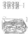
- FIG. 1 is a front, perspective cut-away view of an automated optical disk library.
- FIG. 2 is the same view as in FIG. 1 except that a console panel has been swung aside and a fan has been removed.
- FIG. 3 is a rear perspective cut-away view of the automated optical disk library of FIGS. 1 and 2.
- FIG. 4 is a block diagram of an object storage hierarchy utilizing Object Access Method software to manage objects in an automated optical disk library.
- FIG. 5A is a table representation of a portion of a deleted objects table.
- FIG. 5B is a table representation of a portion of a volume table.
- FIG. 6 is a flow diagram of a routine for managing delete requests in an automated optical disk library of the present invention.
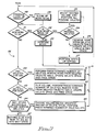
- FIG. 7 is a flow diagram of a task which is part of a method of deleting objects in an automated optical disk library of the present invention.
- FIG. 8 is a flow diagram of a routine for reclaiming space on an optical disk in the present invention.
- the library 1 includes a housing 2 enclosing most of the working parts of the library 1 and having front and rear door panels (not shown) for interior access.
- Library 1 also includes a plurality of optical disk storage cells 3 and a plurality of internal optical disk drives 4.
- Each storage cell 3 is capable of storing one optical disk having data recorded on one or both sides thereof. The data stored on each side of a disk is referred to as a volume so that there are two volumes per disk.
- Automated optical disk library 1 includes 144 storage cells 3 arranged in two 72 storage cell columns and up to four internal optical disk drives 4.
- a robotic picker 5 includes a single gripper 6 capable of accessing an optical disk in any of the storage cells 3 or optical disk drives 4 and transferring such optical disks therebetween.
- the optical disks are configured in cartridges for easy handling by the gripper 6 and are 5 1/4 inch form factor disks, but alternative embodiments could be any size compatible with the optical disk drives 4 and the gripper 6.
- the front face of the housing 2 is not shown in FIG. 1, certain portions of the library 1 protrude through such front face of the housing 2 for operator access. These portions are part of a console door 7 and include all or part of a power indicator/switch 8, an entry/exit slot 9, an external optical disk drive 10, a console 11, and a keyboard 12.
- the console door 7 can be swung aside to allow access therebehind.
- the slot 9 is used for inserting optical disks to or removing optical disks from the library 1. Commands may be provided by an operator to the library 1, via the keyboard 12, to have the robotic picker 5 receive an optical disk inserted at the slot 9 and transport such optical disk to a storage cell 3 or optical disk drive 4 and deliver such optical disk to the slot 9 for removal from the library 1.
- Console 11 allows an operator to monitor and control certain operations of the library 1 without seeing inside the housing 2. External optical disk drive 10 cannot be accessed by the gripper 6 but must be loaded and unloaded manually.
- the library 1 also includes an optical disk drive exhaust fan 14, an external disk drive exhaust fan 15, and power supplies 16.
- the system controller 17 is an IBM PS/2 Model 80 personal computer using the OS/2 operating system.
- the system controller 17 includes main memory and one or more storage media, such as those in fixed or floppy disk drives.
- the system controller 17 issues instructions to the optical disk drives 4, the external optical disk drive 10, and the robotic picker 5.
- Drive controller card 13 and robotic picker controller card 18 convert known small computer system interface (SCSI) command packets issued by the system controller 17 into an electro-mechanical action of the optical disk drives 4, the external optical disk drive 10, and the robotic picker 5.
- SCSI small computer system interface
- FIG. 4 a block diagram of an object storage hierarchy 35 is shown which includes a management and first level storage 21, a second level storage 31 and the automated storage library 1 providing a third level of storage.
- a fourth level of storage is provided by a shelf 36.
- the shelf 36 stores optical disk volumes which are manually loaded into the the external optical disk drive 10 for reading, writing and deleting data therefrom.
- the management and first level storage 21 further includes an application interface 22, a relational database management system (DB2) 24 and an OAM 27.
- Application interface 22 is typically a workstation server which has the capability of sending and receiving scanned documents (objects) and interfacing to DB2 24 and OAM 27 via Object Storage and Retrieval software (OSR) 23.
- OSR Object Storage and Retrieval software
- OSR 23 provides an application program interface for storing, retrieving, and deleting individual objects. OSR 23 also maintains information about objects in DB2 24 including object name, size, location, creation date, last reference date, etc.
- DB2 24 and OAM 27 is stored on a mainframe computer (not shown) as part of MVS/DFP operating system wherein the mainframe computer includes main memory as the first level of storage in the object storage hierarchy 35.
- DB2 24 includes directory and object tables 25 and configuration tables 26 which are connected to OSR 23 for storing object information thereon.
- OAM 27 includes OAM Storage Management Component (OSMC) 28 and Library Control System (LCS) 29.
- OSMC 28 is connected to the LCS 29, to the OSR 23, and to the directory and object tables 25.
- the function of the OSMC 28 is to manage an inventory of hundreds of millions of objects within an object storage hierarchy based on a specified storage management policy.
- OSMC 28 management includes determining where objects are to be stored, moving objects within an object storage hierarchy, managing object backup, and determining object expiration.
- LCS 29 is connected to the OSR 23, the configuration tables 26, and to the system controller 17 of the automated optical disk library 1.
- LCS 29 reads and writes objects to optical disks, manages volumes storing those objects, and controls the system controller 17.
- the second level storage 31 includes DASDs DIR 32, STORE 33, and Configuration Database (CDB) 34.
- the DIR 32 stores directory information of stored objects
- the STORE 33 stores objects
- the CDB 34 stores several tables including a deleted objects table, a volume table, a library table, a cell table, and a drive table.
- CDB 34 is connected to the configuration tables 26, and DIR 32 and Store 33 are connected to the directory and object tables 25.
- the third level of storage includes the automated optical disk library 1 having the system controller 17 connected to the storage cell 3 and the robotic picker 5, the optical disk drives 4 consisting of drives 0-3, and to the external optical disk drive 10.
- the fourth level of storage is provided by the shelf 36 which is interfaced to the automated optical disk library 1 by an operator transferring optical disks therebetween.
- FIGS. 5A and 5B show a portion of a deleted objects table 38 and a portion of a volume table 39, respectively, that are stored on the CDB 34.
- Each row of the deleted objects table 38 stores information about an object that is to be deleted.
- Each row of the deleted objects table 38 includes: the name of the collection that that the object is stored in (collection name); the object name; the identification of the volume the object is stored on (VOLSER); and the size of the object in bytes.
- Each row in the volume table 39 stores information about a volume in the automated optical disk library 1 (and in the shelf 36).
- Stored volume information includes: the volume identification (VOLSER); the identification of the opposite side of the volume (OVOLSER); the amount of current free space in kilobytes (1 kilobyte equals 1024 bytes); the number of objects to be deleted (delete count); the amount of space used by the objects that are to be deleted in kilobytes (delete space); and whether the volume is empty or not (volume empty).
- VOLSER volume identification
- OVOLSER the identification of the opposite side of the volume
- the amount of current free space in kilobytes (1 kilobyte equals 1024 bytes)
- the number of objects to be deleted delete count
- the amount of space used by the objects that are to be deleted in kilobytes delete space
- volume empty volume empty
- step 41 delete requests are received in the LCS 29.
- the delete request can be user initiated, as generated in the application interface 22, or the delete request can be the result of an expired object, as generated in the OSMC 28.
- the LCS 29 receives a delete request for an object residing on a rewritable optical disk volume, a row entry is made in the deleted objects table 38 as shown by step 42.
- the first row in the deleted objects table 38 shows that object A1 of the collection XYZ is stored on volume ABC and uses 4096 bytes of space.
- the space associated with the object to be deleted is logically deleted from the corresponding volume in step 43.
- the size of the object to be deleted is added to the delete space for that volume and a delete count is incremented by one for that volume in the volume table 39.
- the sum of the space of the pending deletes equals 7 kilobytes and is represented in the delete space of the volume table 39 for volume ABC by the 7 recorded therein.
- Step 44 includes adding the logically deleted space to a potential free space of volume ABC.
- the last delete request caused the delete space to increase from 7 to 9 and the step 44 then causes the potential free space to be equal to the sum of the current free space, 28, plus the delete space, 9, for a total of 37 kilobytes.
- the potential free space is calculated and used in an LCS volume selection algorithm described below. Performing the physical delete of the objects depends upon the other requests that are pending for the volume and whether the volume is library or shelf-resident.
- FIG. 7 is a flow diagram representation of a task 66 for deleting objects from a volume in the automated optical disk library 1.
- a task 66 exists for each optical disk drive 4 and for the external optical disk drive 10 such that in the automated optical disk library 1 five tasks 66 could be running concurrently.
- a dispatcher (not shown) controls each task 66 by providing work thereto.
- the first step in the task 66 is to determine whether a request to cleanup is pending as shown in step 48. Cleanup requests result from previous work performed, for example a write request, wherein not all details of the work was completed. If a cleanup request is pending the associated work to be done is completed in step 49. Only after determining that no cleanup work needs to be done or after completing that cleanup work does the task 66, in step 51, check to see if there is any new pending work to be done.
- step 59 determines whether there are pending deletes to be processed.
- the task 66 determines what type of work is pending and, depending on the type of work pending, whether any deletes are also pending.
- Step 52 tests whether the new pending work is a write or defray request. New pending work that is other than a write or defray request is immediately performed in step 53 after which control is returned to the dispatcher. If a write or defray request is pending for a given volume, control is transferred to step 54 for determining whether there are any pending deletes for that volume. In the case of no pending deletes for the given volume, that volume will be mounted and the write or defray request is performed in step 57.
- step 54 determines that deletes are pending, control will be transferred to step 55 where that volume will be mounted on the optical disk drive 4 or the external optical disk drive 10 for which the task 66 is running. All pending deletes for that volume will be performed prior to the write or defray request regardless of whether the volume is library or shelf-resident. In the case of write requests, all pending deletes are done before the write request regardless of whether the write request is specific or nonspecific.
- step 55 the volume ABC will be mounted if it is not already mounted so that the volume ABC becomes a currently mounted volume (CMV). All pending deletes for the volume ABC are also performed by sending commands to the system controller 17 to physically delete each object and to reclaim space allocated to each deleted object.
- step 56 the logically deleted space is added to the current free space for the volume ABC and is reflected in the volume table 39. The rows of pending deletes for the volume ABC in the deleted objects table 38 are also deleted. Thus, the first three rows of the deleted objects table 38 would be removed in step 56.
- step 57 the write or defray request is performed. After step 57 is performed control returns to the dispatcher.
- the pending deletes are performed before the write command because the LCS volume selection algorithm considers the logically deleted space to be part of the potential free space of the volume.
- the LCS algorithm adds the logically deleted space to the current free space to determine the potential free space.
- the potential free space is used when determining which volume has the least amount of free space but can still accommodate the object to be written in a non-specific write request. For specific write requests the potential free space is used to determine whether the requested volume can accommodate the object to be written.
- performing all pending deletes prior to processing a defray request reduces the time necessary to perform the defray request by reducing the amount of data that must be moved in order to defragment the volume.
- the volume ABC has only been mounted once to perform all of the pending deletes and the write or defray request.
- step 51 if no new work is pending then control drops down to step 59 for determining, in the event of an idle period, whether there are any pending deletes for the CMV.
- An idle period exists when the task seeking work makes a complete pass through the dispatcher without receiving any work to do. Having no work for the task to do, the dispatcher tries to find deletes for the task to perform.
- steps 59 through 65 pending deletes for library-resident volumes are performed during periods of library inactivity. When an optical disk drive 4 is avail-able and no other requests are pending then pending deletes will be scheduled for the available optical disk drive.
- the pending deletes are performed in the following priority: pending deletes for the CMV; pending deletes for the opposite side of the currently mounted volume (OCMV); and pending deletes for the library-resident unmounted volume leaving the greatest amount of logically deleted space.
- step 59 a determination is made as to whether there are any pending deletes for the volume ABC. If there are pending deletes for the volume ABC then a predetermined number of the pending deletes will be per-formed in step 61 by sending a DELETE command to the system controller 17 which prompts the optical disk drive 4 having the volume ABC mounted thereon for removing the directory entries for the deleted objects and physically reclaiming the space allocated to each deleted object. For example, up to 10 objects may be deleted from the volume ABC in step 61. Limiting the number of pending deletes performed during an idle period prevents excessive delays of servicing other object or volume requests.
- the corresponding rows in the deleted objects table 38 are deleted by issuing a SQL DELETE command (Structured query Language).
- the delete space and current free space are also updated by adding the space of the deleted objects to the free space in the volume table 39.
- control After updating the current free space for the CMV control returns to the dispatcher to again determine whether there is any pending work. If other pending work has been received then control goes back to steps 48-57. As long as there is no other pending work then steps 59 and 61 will be repeated until all pending deletes are processed for the CMV. If no more pending deletes are found in step 59 then control goes to step 62 where a determination is made, in the event of an idle period, whether there are any pending deletes for the opposite side of the CMV (OCMV), in this case for the volume DEF. If there are pending deletes for the OCMV then in step 63 the robotic picker 5 will be instructed to turn the CMV over so that the OCMV is mounted.
- OCMV opposite side of the CMV
- Step 63 proceeds to perform a predetermined number of pending deletes on the volume DEF followed by removing the corresponding rows from the deleted objects table and updating the delete space and free space in the volume table 39.
- step 63 control returns to the dispatcher and the steps 48-57 are repeated as necessary.
- the volume DEF is no longer the OCMV but is the CMV so that if any pending deletes remain for the volume DEF they will be performed in steps 59 and 61. If upon the completion of deleting objects on the volume DEF more deletes request were made for the volume ABC, now the OCMV, then steps 62, and 63 will be again performed to delete those objects during idle periods when no other work is pending.
- step 62 exits to step 64.
- step 64 a determination is made, in the event of an idle period, whether there is a volume accessible to the internal optical disk drive 4 which has pending deletes. If such accessible volumes do exist, then step 65 identifies the library-resident volume having the greatest amount of logically deleted space by inspecting the volume table 39. This identified volume will be mounted thus becoming the new CMV. Once again a predetermined number of pending deletes will be performed followed by removal or the corresponding rows from the deleted objects table 38 and the delete space and free space of the volume table 39 will be updated.
- step 67 the task 66 falls into a wait state.
- Pending deletes for shelf-resident volumes are also performed during periods of inactivity but only for those volumes currently mounted on the external optical disk drive 10. An operator will not be prompted by the LCS 29 to flip a currently mounted volume or to mount a shelf-resident optical disk volume for the purpose of performing pending deletes. This avoids unnecessarily tying up the external optical disk drive 10 due to an operator not being immediately available to respond to the prompt.
- Psuedo code for the task 66 is given below as an example of how to carry out the steps 48-65 of FIG. 7.
- LCS 29 will eject the least recently mounted optical disk for storage on the shelf 36 so that an optical disk having more free space may be loaded into the automated optical disk library 1. Based on the rate at which new objects are created and the size of the new objects, it is very likely that by the time all of the objects on a volume expire that that volume will be shelf-resident. Delete requests for objects residing on shelf-resident volumes are processed similarly to the delete requests for objects on library-resident volumes. Since only pending deletes for the shelf-resident volume currently mounted on the external optical disk drive 10 are serviced it is expected that the vast majority of pending deletes will be for shelf-resident volumes. These unprocessed pending deletes require a significant amount of space on the CDB 34 due to the rows used in the deleted objects table 38 to represent the pending deletes.
- each volume has an expiration date which is calculated as objects are written to that volume.
- the expiration date of a volume is the same date as the expiration date of the object stored on that volume having the latest expiration date.
- An expiration date for an optical disk is defined by the volume of that optical disk having the latest expiration date.
- the expiration date is checked for each volume in the automated optical disk library 1 and in the shelf 36.
- the OSMC 28 performs the check at a predetermined time each day, for example, a time when low activity an the automated optical disk library 1 is expected.
- the OSMC 28 communicates to the LCS 29 which volumes have reached their expiration date in step 72 and the LCS 29 sets the "volume empty” status to "Y" for those empty volumes in the volume table 39.
- a volume is not considered empty unless all objects residing on both volumes of an optical disk have expired. If all of the objects on either volume of an optical disk have not expired, then neither volume will be considered empty and the "volume empty" field for those volumes will be set to "N".
- All of the rows in the deleted objects table 38 for the pending deletes associated with a volume that has had its volume empty status set to "Y" are deleted in step 73 and the delete space and free space are updated. Since a volume is not considered empty unless both volumes thereon are empty, the pending deletes for both volumes will be deleted.
- a single SQL DELETE command can delete all of the rows for an empty volume; this is far more efficient than deleting the rows one at a time.
- space on the CDB 34 is made available sooner than if waiting till the empty volume was mounted during an idle period. When both volumes on an optical disk have reached their expiration date both volumes will have their volume empty status set to "Y" and the expired status for those volumes will be set.
- step 74 Each time a volume is mounted its expired status is checked in step 74. If the expired status is set then the optical disk containing that volume is reformatted by issuing a FORMAT command to the system controller in step 75. Reformatting the disk involves reformatting the mounted volume, flipping the disk, and reformatting the opposite side. Reformatting results in reclaiming all of the space on the optical disk by causing the file format control structures on the optical disk to be updated and all of the space thereon being made available for use. All objects on the optical disk are physically deleted so that the space is reclaimed for writing new objects. In step 76 the expired status is reset and the volume table 39 is updated to show the amount of free space, volume empty status, etc.
Abstract
Description
- This invention relates generally to hierarchical data storage systems.
- Computers are required to process, and hence store, large amounts of information. Fast processing of information requires that the central processing unit of these computers be able to transfer that information at a high speed. The storage medium used to store information will typically be the limiting factor of the transfer rates.
- The fastest storage medium in a computer is main memory which is usually in the form of semiconductor dynamic random access memory (DRAM). While main memory is very fast it is also very expensive relative to other forms of storage media and the amount of main memory that can be economically provided falls far short of the overall storage requirements. Main memory use is thus limited to short term storage of currently active information. The remaining information storage requirements are typically handled by peripheral storage devices.
- Peripheral storage devices include magnetic tape storage devices, Direct Access Storage Devices (DASD), and optical storage devices. Each of these storage devices has a substantially greater storage density and lower cost than main memory. However, the time to access information from each of these storage devices is also much greater than the access time of information from main memory. For example, main memory is accessed electronically and no mechanical movement is required. Peripheral storage devices, on the other hand, require that a particular area of a tape or disk first be positioned under a read/write head before information accessing can begin.
- Some applications must store and retrieve such large amounts of information that many storage devices are required. In these applications the user typically requires a hierarchy of storage that includes some combination of main memory and one or more types of peripheral storage devices. The goal of the hierarchy is to obtain moderately priced high capacity storage while maintaining high speed access to the stored information. Hierarchical storage typically allows information to be transferred between main memory and one or more of the peripheral storage devices or between one or more peripheral storage device and one or more other peripheral storage devices. Further storage is provided by maintaining libraries of data storage media such as tapes, magnetic disks or optical disks that can be mounted onto the existing peripheral devices. However, additional delays of accessing the information is introduced due to the necessity of having to manually locate and then load, for example, an optical disk onto an optical drive.
- Automated storage libraries improve the access time to information stored on a tape, magnetic disk, or optical disk contained therein by automatically managing the storage of such tapes and disks. Automated storage libraries include a plurality of storage cells for storing library-resident data storage media, a robotic picker mechanism, and one or more internal peripheral storage devices. Each data storage medium may be contained in a cassette or cartridge housing for easier handling by the picker. The picker operates on command to transfer a data storage medium between a storage cell and an internal peripheral storage device within seconds. A significant improvement in access time to the desired information is provided since the picker mechanism operates much faster to transfer a storage medium than does a manual operation. Still more storage may be provided by including an external shelf for storing additional data storage media which may be manually inserted into the automated storage library.
- The improved response time provided by automated storage libraries has made it feasible to store a large number of images as a data type for computer processing. Such images include engineering drawings, financial and insurance documents, medical charts and records, voice data, etc. These images are known as objects in order to identify them as data elements having an unconventional data structure. Text, a conventional data structure, is encoded on a storage medium in streams of binary 1′s and 0′s of fixed lengths. An object, on the other hand, is a named stream of binary 1′s and 0′s of a known length. The length of the stream of bits is not fixed but may vary from a few bytes to several megabytes.
- Optical disks provide the highest density of the disk storage media and hence an automated optical disk library is most suitable for storing large object databases. Examples of optical disk libraries are given in U.S. Patents 4,271,489, 4,527,262 and 4,614,474. Each optical disk in an optical disk library consists of two logical volumes so that there is one volume per side. To access objects on a given volume, that volume is retrieved from the library by the picker and mounted onto an internal optical drive. This may require that a presently mounted volume first be demounted and stored in the library by the picker.
- Hundreds of millions of objects can be stored in an automated optical disk library. Efficient management is a necessity given the large number of objects handled. Management is provided by object management software. An example of such object management software is Object Access Method software (OAM). OAM is a subcomponent of an IBM program product, Multiple Virtual Storage/Data Facility Product software (MVS/DFP), which manages the hundreds of millions of objects. OAM keeps an inventory of each object including its location information in an OAM object directory. Library Control System software (LCS) is a subcomponent of OAM for processing a variety of requests affecting the optical disks. Processing the requests requires that the corresponding volume be mounted on an optical drive. If that volume is library-resident the picker automatically moves the optical disk cartridge from the storage area to an optical drive. If the volume is shelf-resident, then mounting is accomplished with human intervention. In cases of shelf-resident volumes, LCS issues a message to an operator regarding the shelf location and the optical drive designated to receive the volume.
- LCS performs volume requests which are those requests that affect a volume as a whole. Volume requests include the requests for auditing or defragmenting a volume. A volume is audited by retrieving and mounting that volume for the purpose of verifying that the optical disk cartridge containing the volume is actually present within the library. Defragmenting a volume entails moving data recorded on a volume in order to reduce the number of free extents thereby increasing the size of the free extents. Each free extent consists of one or more adjacent sectors wherein no two free extents are contiguous. Increasing the size of the free extents increases the probability that a file will be able to occupy a single contiguous area. This in turn reduces the time required to read such a file since seek operations to different physical areas of the surface of the volume are not required when sequentially reading a file. Normally there will be relatively few volume requests pending for a given volume.
- LCS also performs object requests which are requests to perform an operation on an object. Object requests include requests to read, write, or delete an object from a volume. Write requests further include specific and nonspecific write requests. A specific write request identifies a specific volume to be written to. A nonspecific write request only identifies a storage group from which a volume may be chosen according to a LCS volume selection algorithm. A storage group is a collection of optical disk volumes having some specified attributes in common. Volume selection is determined by choosing the volume having the least amount of available space yet capable of accommodating the object or objects to be written. Deleting an object may be accomplished by simply mounting the volume containing the object to be deleted and deleting the object. Similarly, a read request is serviced by mounting the correct volume and reading the object therefrom. There can be a large number of object requests pending for any one given volume.
- Due to the large number of requests that may be queued up in an automated library it is necessary to manage the queued requests efficiently. The manner in which the queued requests are executed has a significant impact on the efficiency of information access. Efficiency can be improved by prioritizing requests according to predetermined attributes, for example, according to the information presently stored in main memory, on a first-in first-out basis, or according to the volumes already mounted in the peripheral devices. These prioritization techniques are described in commonly assigned Patent Application 07/317,493 filed March 1, 1989. Blount, et al., in U.S. Patent 4,974,197 describe a method of improving the efficiency of writing a Volume Table of Contents (VTOC) and the associated objects to an optical disk by collecting a given number of predetermined objects such that a single access writes the objects and the corresponding VTOC entry.
- Mounting a volume, even if done by the robotic picker, is very slow relative to the seek time of an object plus the writing, reading or deleting time of even large objects. Performing many mounts, therefore, substantially slows the servicing of the pending requests. The efficiency of an automated library could be improved by reducing the number of mounts for a given number of volume and object requests.
- It is accordingly an object of the present invention to provide hierarchical data storage systems with improved means for deleting ojbects from volumes.
- According to the invention there is provided in hierarchical data storage system, a method of deleting objects from volumes comprising the steps of receiving a delete request for deleting an object from a first volume, writing the delete request to a deleted objects table such that the delete request is added to a list of pending deletes for the first volume, logically deleting the space associated with the delete request, receiving a write request for the first volume, mounting the first volume on a drive if the first volume is not already mounted, deleting all of the objects on the first volume that are listed in the list of pending deletes, adding logically deleted space of the first volume to current free space of the first volume, and performing the write request.
- There is further provided a hierarchical storage system having a plurality of levels of storage for managing objects therein, one level of storage being an automated library having a plurality of storage media for storing objects thereon, comprising storage means for storing a storage management software, a control unit coupled to said storage means for receiving commands therefrom, optical storage and retrieval means coupled to said storage means for receiving volume and object requests, wherein volume requests include defragment and reclamation requests and object requests include read, write, and delete requests, object table means coupled to said storage means for storing delete requests into pluralities of pending deletes, each one of the plurality of pending deletes grouped according to a volume the objects to be deleted are stored on, and a first drive coupled to said control unit for executing the pending deletes for a predetermined volume just prior to a write request being executed for the predetermined volume.
- In order that the invention may be well understood, a preferred embodiment thereof will now be described with reference to the accompanying drawings, in which:
- FIG. 1 is a front, perspective cut-away view of an automated optical disk library.
- FIG. 2 is the same view as in FIG. 1 except that a console panel has been swung aside and a fan has been removed.
- FIG. 3 is a rear perspective cut-away view of the automated optical disk library of FIGS. 1 and 2.
- FIG. 4 is a block diagram of an object storage hierarchy utilizing Object Access Method software to manage objects in an automated optical disk library.
- FIG. 5A is a table representation of a portion of a deleted objects table.
- FIG. 5B is a table representation of a portion of a volume table.
- FIG. 6 is a flow diagram of a routine for managing delete requests in an automated optical disk library of the present invention.
- FIG. 7 is a flow diagram of a task which is part of a method of deleting objects in an automated optical disk library of the present invention.
- FIG. 8 is a flow diagram of a routine for reclaiming space on an optical disk in the present invention.
- Referring now more particularly to the drawing, like numerals denote like features and structural elements in the various figures. Referring to FIGS. 1-3, various views of an automated optical disk library 1 are shown. The library 1 includes a
housing 2 enclosing most of the working parts of the library 1 and having front and rear door panels (not shown) for interior access. Library 1 also includes a plurality of opticaldisk storage cells 3 and a plurality of internal optical disk drives 4. Eachstorage cell 3 is capable of storing one optical disk having data recorded on one or both sides thereof. The data stored on each side of a disk is referred to as a volume so that there are two volumes per disk. Automated optical disk library 1 includes 144storage cells 3 arranged in two 72 storage cell columns and up to four internal optical disk drives 4. - A
robotic picker 5 includes a single gripper 6 capable of accessing an optical disk in any of thestorage cells 3 oroptical disk drives 4 and transferring such optical disks therebetween. The optical disks are configured in cartridges for easy handling by the gripper 6 and are 5 1/4 inch form factor disks, but alternative embodiments could be any size compatible with theoptical disk drives 4 and the gripper 6. - Although the front face of the
housing 2 is not shown in FIG. 1, certain portions of the library 1 protrude through such front face of thehousing 2 for operator access. These portions are part of aconsole door 7 and include all or part of a power indicator/switch 8, an entry/exit slot 9, an externaloptical disk drive 10, a console 11, and akeyboard 12. Theconsole door 7 can be swung aside to allow access therebehind. Theslot 9 is used for inserting optical disks to or removing optical disks from the library 1. Commands may be provided by an operator to the library 1, via thekeyboard 12, to have therobotic picker 5 receive an optical disk inserted at theslot 9 and transport such optical disk to astorage cell 3 oroptical disk drive 4 and deliver such optical disk to theslot 9 for removal from the library 1. Console 11 allows an operator to monitor and control certain operations of the library 1 without seeing inside thehousing 2. Externaloptical disk drive 10 cannot be accessed by the gripper 6 but must be loaded and unloaded manually. The library 1 also includes an optical diskdrive exhaust fan 14, an external diskdrive exhaust fan 15, and power supplies 16. - Once the library 1 is powered on, commands received at the
keyboard 12 are forwarded to asystem controller 17. In the preferred embodiment, thesystem controller 17 is an IBM PS/2 Model 80 personal computer using the OS/2 operating system. Thesystem controller 17 includes main memory and one or more storage media, such as those in fixed or floppy disk drives. Thesystem controller 17 issues instructions to theoptical disk drives 4, the externaloptical disk drive 10, and therobotic picker 5. Drive controller card 13 and roboticpicker controller card 18 convert known small computer system interface (SCSI) command packets issued by thesystem controller 17 into an electro-mechanical action of theoptical disk drives 4, the externaloptical disk drive 10, and therobotic picker 5. - Referring now to FIG. 4, a block diagram of an
object storage hierarchy 35 is shown which includes a management andfirst level storage 21, a second level storage 31 and the automated storage library 1 providing a third level of storage. A fourth level of storage is provided by ashelf 36. Theshelf 36 stores optical disk volumes which are manually loaded into the the externaloptical disk drive 10 for reading, writing and deleting data therefrom. The management andfirst level storage 21 further includes anapplication interface 22, a relational database management system (DB2) 24 and anOAM 27.Application interface 22 is typically a workstation server which has the capability of sending and receiving scanned documents (objects) and interfacing toDB2 24 andOAM 27 via Object Storage and Retrieval software (OSR) 23. -
OSR 23 provides an application program interface for storing, retrieving, and deleting individual objects.OSR 23 also maintains information about objects inDB2 24 including object name, size, location, creation date, last reference date, etc.DB2 24 andOAM 27 is stored on a mainframe computer (not shown) as part of MVS/DFP operating system wherein the mainframe computer includes main memory as the first level of storage in theobject storage hierarchy 35.DB2 24 includes directory and object tables 25 and configuration tables 26 which are connected toOSR 23 for storing object information thereon. -
OAM 27 includes OAM Storage Management Component (OSMC) 28 and Library Control System (LCS) 29.OSMC 28 is connected to theLCS 29, to theOSR 23, and to the directory and object tables 25. The function of theOSMC 28 is to manage an inventory of hundreds of millions of objects within an object storage hierarchy based on a specified storage management policy.OSMC 28 management includes determining where objects are to be stored, moving objects within an object storage hierarchy, managing object backup, and determining object expiration.LCS 29 is connected to theOSR 23, the configuration tables 26, and to thesystem controller 17 of the automated optical disk library 1.LCS 29 reads and writes objects to optical disks, manages volumes storing those objects, and controls thesystem controller 17. - The second level storage 31 includes
DASDs DIR 32,STORE 33, and Configuration Database (CDB) 34. TheDIR 32 stores directory information of stored objects, theSTORE 33 stores objects, and theCDB 34 stores several tables including a deleted objects table, a volume table, a library table, a cell table, and a drive table.CDB 34 is connected to the configuration tables 26, andDIR 32 andStore 33 are connected to the directory and object tables 25. The third level of storage includes the automated optical disk library 1 having thesystem controller 17 connected to thestorage cell 3 and therobotic picker 5, theoptical disk drives 4 consisting of drives 0-3, and to the externaloptical disk drive 10. The fourth level of storage is provided by theshelf 36 which is interfaced to the automated optical disk library 1 by an operator transferring optical disks therebetween. - FIGS. 5A and 5B show a portion of a deleted objects table 38 and a portion of a volume table 39, respectively, that are stored on the
CDB 34. Each row of the deleted objects table 38 stores information about an object that is to be deleted. Each row of the deleted objects table 38 includes: the name of the collection that that the object is stored in (collection name); the object name; the identification of the volume the object is stored on (VOLSER); and the size of the object in bytes. Each row in the volume table 39 stores information about a volume in the automated optical disk library 1 (and in the shelf 36). Stored volume information includes: the volume identification (VOLSER); the identification of the opposite side of the volume (OVOLSER); the amount of current free space in kilobytes (1 kilobyte equals 1024 bytes); the number of objects to be deleted (delete count); the amount of space used by the objects that are to be deleted in kilobytes (delete space); and whether the volume is empty or not (volume empty). In the volume table 39 the first two rows contain information about volume ABC and the opposite side DEF, respectively. - Referring now to FIG. 6 a flow diagram of a routine for managing delete requests is shown. In
step 41 delete requests are received in theLCS 29. The delete request can be user initiated, as generated in theapplication interface 22, or the delete request can be the result of an expired object, as generated in theOSMC 28. When theLCS 29 receives a delete request for an object residing on a rewritable optical disk volume, a row entry is made in the deleted objects table 38 as shown bystep 42. The first row in the deleted objects table 38 shows that object A1 of the collection XYZ is stored on volume ABC and uses 4096 bytes of space. The space associated with the object to be deleted is logically deleted from the corresponding volume instep 43. - To perform the logical delete the size of the object to be deleted is added to the delete space for that volume and a delete count is incremented by one for that volume in the volume table 39. There are currently 3 pending deletes for the objects residing on volume ABC which are stored in the first three rows of the deleted objects table 38 and make up a list of pending deletes for volume ABC. The sum of the space of the pending deletes equals 7 kilobytes and is represented in the delete space of the volume table 39 for volume ABC by the 7 recorded therein. Assuming another delete request is received for an object requiring two kilobytes of space and residing on the volume ABC, then a row describing the object would be added to the deleted objects table, the delete space would be increased to 9, and the delete count would be increased to 4.
Step 44 includes adding the logically deleted space to a potential free space of volume ABC. According to the last example, the last delete request caused the delete space to increase from 7 to 9 and thestep 44 then causes the potential free space to be equal to the sum of the current free space, 28, plus the delete space, 9, for a total of 37 kilobytes. The potential free space is calculated and used in an LCS volume selection algorithm described below. Performing the physical delete of the objects depends upon the other requests that are pending for the volume and whether the volume is library or shelf-resident. - FIG. 7 is a flow diagram representation of a
task 66 for deleting objects from a volume in the automated optical disk library 1. Atask 66 exists for eachoptical disk drive 4 and for the externaloptical disk drive 10 such that in the automated optical disk library 1 fivetasks 66 could be running concurrently. A dispatcher (not shown) controls eachtask 66 by providing work thereto. The first step in thetask 66 is to determine whether a request to cleanup is pending as shown instep 48. Cleanup requests result from previous work performed, for example a write request, wherein not all details of the work was completed. If a cleanup request is pending the associated work to be done is completed instep 49. Only after determining that no cleanup work needs to be done or after completing that cleanup work does thetask 66, instep 51, check to see if there is any new pending work to be done. - When there is no new work pending, control is transferred to step 59 to determine whether there are pending deletes to be processed. However, if new work is pending, the
task 66 determines what type of work is pending and, depending on the type of work pending, whether any deletes are also pending.Step 52 tests whether the new pending work is a write or defray request. New pending work that is other than a write or defray request is immediately performed instep 53 after which control is returned to the dispatcher. If a write or defray request is pending for a given volume, control is transferred to step 54 for determining whether there are any pending deletes for that volume. In the case of no pending deletes for the given volume, that volume will be mounted and the write or defray request is performed instep 57. - Should step 54 determine that deletes are pending, control will be transferred to step 55 where that volume will be mounted on the
optical disk drive 4 or the externaloptical disk drive 10 for which thetask 66 is running. All pending deletes for that volume will be performed prior to the write or defray request regardless of whether the volume is library or shelf-resident. In the case of write requests, all pending deletes are done before the write request regardless of whether the write request is specific or nonspecific. - Assuming a write request is received for the volume ABC, in
step 55 the volume ABC will be mounted if it is not already mounted so that the volume ABC becomes a currently mounted volume (CMV). All pending deletes for the volume ABC are also performed by sending commands to thesystem controller 17 to physically delete each object and to reclaim space allocated to each deleted object. Instep 56 the logically deleted space is added to the current free space for the volume ABC and is reflected in the volume table 39. The rows of pending deletes for the volume ABC in the deleted objects table 38 are also deleted. Thus, the first three rows of the deleted objects table 38 would be removed instep 56. Instep 57 the write or defray request is performed. Afterstep 57 is performed control returns to the dispatcher. - The pending deletes are performed before the write command because the LCS volume selection algorithm considers the logically deleted space to be part of the potential free space of the volume. As described above, the LCS algorithm adds the logically deleted space to the current free space to determine the potential free space. The potential free space is used when determining which volume has the least amount of free space but can still accommodate the object to be written in a non-specific write request. For specific write requests the potential free space is used to determine whether the requested volume can accommodate the object to be written. Similarly, performing all pending deletes prior to processing a defray request reduces the time necessary to perform the defray request by reducing the amount of data that must be moved in order to defragment the volume. Furthermore, the volume ABC has only been mounted once to perform all of the pending deletes and the write or defray request.
- Returning to step 51, if no new work is pending then control drops down to step 59 for determining, in the event of an idle period, whether there are any pending deletes for the CMV. An idle period exists when the task seeking work makes a complete pass through the dispatcher without receiving any work to do. Having no work for the task to do, the dispatcher tries to find deletes for the task to perform. In
steps 59 through 65 pending deletes for library-resident volumes are performed during periods of library inactivity. When anoptical disk drive 4 is avail-able and no other requests are pending then pending deletes will be scheduled for the available optical disk drive. The pending deletes are performed in the following priority: pending deletes for the CMV; pending deletes for the opposite side of the currently mounted volume (OCMV); and pending deletes for the library-resident unmounted volume leaving the greatest amount of logically deleted space. - Assuming the volume ABC is the CMV, in step 59 a determination is made as to whether there are any pending deletes for the volume ABC. If there are pending deletes for the volume ABC then a predetermined number of the pending deletes will be per-formed in
step 61 by sending a DELETE command to thesystem controller 17 which prompts theoptical disk drive 4 having the volume ABC mounted thereon for removing the directory entries for the deleted objects and physically reclaiming the space allocated to each deleted object. For example, up to 10 objects may be deleted from the volume ABC instep 61. Limiting the number of pending deletes performed during an idle period prevents excessive delays of servicing other object or volume requests. After the predetermined number of pending deletes are performed the corresponding rows in the deleted objects table 38 are deleted by issuing a SQL DELETE command (Structured query Language). The delete space and current free space are also updated by adding the space of the deleted objects to the free space in the volume table 39. - After updating the current free space for the CMV control returns to the dispatcher to again determine whether there is any pending work. If other pending work has been received then control goes back to steps 48-57. As long as there is no other pending work then steps 59 and 61 will be repeated until all pending deletes are processed for the CMV. If no more pending deletes are found in
step 59 then control goes to step 62 where a determination is made, in the event of an idle period, whether there are any pending deletes for the opposite side of the CMV (OCMV), in this case for the volume DEF. If there are pending deletes for the OCMV then instep 63 therobotic picker 5 will be instructed to turn the CMV over so that the OCMV is mounted. When the OCMV is mounted it becomes the CMV, thus the volume DEF is now the CMV.Step 63 then proceeds to perform a predetermined number of pending deletes on the volume DEF followed by removing the corresponding rows from the deleted objects table and updating the delete space and free space in the volume table 39. - When
step 63 is completed control returns to the dispatcher and the steps 48-57 are repeated as necessary. When control returns to step 59, however, the volume DEF is no longer the OCMV but is the CMV so that if any pending deletes remain for the volume DEF they will be performed insteps - When there are no pending deletes to he performed for both the CMV and the OCMV then step 62 exits to step 64. In step 64 a determination is made, in the event of an idle period, whether there is a volume accessible to the internal
optical disk drive 4 which has pending deletes. If such accessible volumes do exist, then step 65 identifies the library-resident volume having the greatest amount of logically deleted space by inspecting the volume table 39. This identified volume will be mounted thus becoming the new CMV. Once again a predetermined number of pending deletes will be performed followed by removal or the corresponding rows from the deleted objects table 38 and the delete space and free space of the volume table 39 will be updated. Any remaining pending deletes would be performed insteps step 62 and the process continues. When there is no other pending work and all pending deletes have been performed, then instep 67 thetask 66 falls into a wait state. - Pending deletes for shelf-resident volumes are also performed during periods of inactivity but only for those volumes currently mounted on the external
optical disk drive 10. An operator will not be prompted by theLCS 29 to flip a currently mounted volume or to mount a shelf-resident optical disk volume for the purpose of performing pending deletes. This avoids unnecessarily tying up the externaloptical disk drive 10 due to an operator not being immediately available to respond to the prompt. - Psuedo code for the
task 66 is given below as an example of how to carry out the steps 48-65 of FIG. 7.


- Over time the optical disks in the automated optical disk library become full and some optical disks will eventually have to be ejected.
LCS 29 will eject the least recently mounted optical disk for storage on theshelf 36 so that an optical disk having more free space may be loaded into the automated optical disk library 1. Based on the rate at which new objects are created and the size of the new objects, it is very likely that by the time all of the objects on a volume expire that that volume will be shelf-resident. Delete requests for objects residing on shelf-resident volumes are processed similarly to the delete requests for objects on library-resident volumes. Since only pending deletes for the shelf-resident volume currently mounted on the externaloptical disk drive 10 are serviced it is expected that the vast majority of pending deletes will be for shelf-resident volumes. These unprocessed pending deletes require a significant amount of space on theCDB 34 due to the rows used in the deleted objects table 38 to represent the pending deletes. - Referring now to FIG. 8, a routine for deleting all objects stored on an optical disk is shown. Each volume has an expiration date which is calculated as objects are written to that volume. The expiration date of a volume is the same date as the expiration date of the object stored on that volume having the latest expiration date. An expiration date for an optical disk is defined by the volume of that optical disk having the latest expiration date. In
step 71 the expiration date is checked for each volume in the automated optical disk library 1 and in theshelf 36. TheOSMC 28 performs the check at a predetermined time each day, for example, a time when low activity an the automated optical disk library 1 is expected. TheOSMC 28 communicates to theLCS 29 which volumes have reached their expiration date instep 72 and theLCS 29 sets the "volume empty" status to "Y" for those empty volumes in the volume table 39. A volume is not considered empty unless all objects residing on both volumes of an optical disk have expired. If all of the objects on either volume of an optical disk have not expired, then neither volume will be considered empty and the "volume empty" field for those volumes will be set to "N". - All of the rows in the deleted objects table 38 for the pending deletes associated with a volume that has had its volume empty status set to "Y" are deleted in
step 73 and the delete space and free space are updated. Since a volume is not considered empty unless both volumes thereon are empty, the pending deletes for both volumes will be deleted. A single SQL DELETE command can delete all of the rows for an empty volume; this is far more efficient than deleting the rows one at a time. Furthermore, space on theCDB 34 is made available sooner than if waiting till the empty volume was mounted during an idle period. When both volumes on an optical disk have reached their expiration date both volumes will have their volume empty status set to "Y" and the expired status for those volumes will be set. - Each time a volume is mounted its expired status is checked in
step 74. If the expired status is set then the optical disk containing that volume is reformatted by issuing a FORMAT command to the system controller instep 75. Reformatting the disk involves reformatting the mounted volume, flipping the disk, and reformatting the opposite side. Reformatting results in reclaiming all of the space on the optical disk by causing the file format control structures on the optical disk to be updated and all of the space thereon being made available for use. All objects on the optical disk are physically deleted so that the space is reclaimed for writing new objects. In step 76 the expired status is reset and the volume table 39 is updated to show the amount of free space, volume empty status, etc. - While the invention has been particularly described with reference to particular embodiments thereof, it will be understood by those skilled in the art that various other changes in detail may be made therein without departing from the spirit, scope, and teaching of the invention. For example, the preferred embodiment has been described using optical disks but the invention is equally applicable to other types of libraries such as DASD, floppy disk, tape, etc.
Claims (13)
- In hierarchical data storage system, a method of deleting objects from volumes comprising the steps of
receiving a delete request for deleting an object from a first volume,
writing the delete request to a deleted objects table such that the delete request is added to a list of pending deletes for the first volume,
logically deleting the space associated with the delete request,
receiving a write request for the first volume,
mounting the first volume on a drive if the first volume is not already mounted,
deleting all of the objects on the first volume that are listed in the list of pending deletes,
adding logically deleted space of the first volume to current free space of the first volume, and
performing the write request. - The method according to claim 1 wherein the delete request is user initiated.
- The method according to claim 1 wherein the delete request is machine initiated as the result of an object having expired.
- The method according to claim 3 further comprising the steps of:
determining whether a second volume has expired, and,
if all of the objects on the second volume have expired:
setting a volume empty status for the second volume,
deleting a list of pending deletes for the second volume,
checking the expired status of an optical disk containing the second volume when the second volume is mounted, and
deleting all of the objects or the disk by reformatting the disk if the expired status is set. - The method according to claim 4 further comprising the steps of:
receiving a defragmentation request for a third volume,
mounting the third volume on a drive if the third volume is not already mounted,
deleting all of the objects listed in a list of pending deletes for the third volume,
adding logically deleted space to current free space of the third volume, and
defragmenting the third volume. - The method according to claim 5 further comprising the steps of
deleting a predetermined number of objects from a currently mounted volume during library idle periods,
if there are no objects to be deleted from the currently mounted volume during library idle periods,
mounting the opposite side of the currently mounted volume if the opposite side has pending deletes, and
deleting a predetermined number of objects from the opposite side of the currently mounted volume until all pending deletes have been performed, and
if there are no objects to be deleted from the opposite side of the currently mounted volume during library idle periods,
mounting an unmounted volume having the greatest amount of logically deleted space, and
deleting objects in groups of a predetermined number of objects from said unmounted volume until all pending deletes have been performed. - A hierarchical storage system having a plurality of levels of storage for managing objects therein, one level of storage being an automated library having a plurality of storage media for storing objects thereon, comprising
storage means for storing a storage management software,
a control unit coupled to said storage means for receiving commands therefrom,
optical storage and retrieval means coupled to said storage means for receiving volume and object requests, wherein volume requests include defragment and reclamation requests and object requests include read, write, and delete requests,
object table means coupled to said storage means for storing delete requests into pluralities of pending deletes, each one of the plurality of pending deletes grouped according to a volume the objects to be deleted are stored on, and
a first drive coupled to said control unit for executing the pending deletes for a predetermined volume just prior to a write request being executed for the predetermined volume. - The hierarchical storage system according to claim 7 further comprising a second drive for receiving other disks from an operator.
- The hierarchical storage system according to claim 8 further comprising a shelf for storing said other disks.
- The hierarchical storage system according to claim 9 wherein said storage management software comprises:
a library control system, and an object storage management component. - The hierarchical storage system according to claim 10 wherein said storage and retrieval means issues requests for each object that has expired.
- The hierarchical storage system according to claim 11 wherein pending deletes for a volume mounted in said first drive are executed during idle periods.
- The hierarchical storage system according to claim 12 wherein said first drive executes pending deletes for the predetermined volume before executing a defragmentation request for the predetermined volume.
Applications Claiming Priority (2)
| Application Number | Priority Date | Filing Date | Title |
|---|---|---|---|
| US683768 | 1991-04-10 | ||
| US07/683,768 US5325523A (en) | 1991-04-10 | 1991-04-10 | Method for deleting objects from library resident optical disks by accumulating pending delete requests |
Publications (2)
| Publication Number | Publication Date |
|---|---|
| EP0508755A2 true EP0508755A2 (en) | 1992-10-14 |
| EP0508755A3 EP0508755A3 (en) | 1995-02-08 |
Family
ID=24745373
Family Applications (1)
| Application Number | Title | Priority Date | Filing Date |
|---|---|---|---|
| EP92303127A Withdrawn EP0508755A3 (en) | 1991-04-10 | 1992-04-08 | Hierarchical data storage system |
Country Status (3)
| Country | Link |
|---|---|
| US (1) | US5325523A (en) |
| EP (1) | EP0508755A3 (en) |
| JP (1) | JPH0785351B2 (en) |
Cited By (1)
| Publication number | Priority date | Publication date | Assignee | Title |
|---|---|---|---|---|
| EP0621529A2 (en) * | 1993-04-20 | 1994-10-26 | International Business Machines Corporation | Method and apparatus for recording data on a rewritable optical disk |
Families Citing this family (30)
| Publication number | Priority date | Publication date | Assignee | Title |
|---|---|---|---|---|
| JP3108090B2 (en) * | 1990-11-30 | 2000-11-13 | 株式会社リコー | Data management method and apparatus for firing system |
| JPH06309200A (en) * | 1991-04-10 | 1994-11-04 | Internatl Business Mach Corp <Ibm> | Method for reading object from volume hierarchical type memory system and information processing system |
| JP3612339B2 (en) * | 1992-10-23 | 2005-01-19 | 株式会社日立製作所 | Data processing method and apparatus |
| US5416915A (en) * | 1992-12-11 | 1995-05-16 | International Business Machines Corporation | Method and system for minimizing seek affinity and enhancing write sensitivity in a DASD array |
| US5493724A (en) * | 1993-04-01 | 1996-02-20 | International Business Machines Corporation | Locking a non-busy device for accessing a data record stored on another device |
| US5623693A (en) * | 1994-02-17 | 1997-04-22 | International Business Machines Corporation | System for performing action by sorting actions into immediate and deferred queues, processing immediate queue while still sorting, and appending deferred queue to immediate after sorting |
| JP3037874B2 (en) * | 1994-04-29 | 2000-05-08 | インターナショナル・ビジネス・マシーンズ・コーポレイション | Library management system and method |
| JPH0877073A (en) * | 1994-08-31 | 1996-03-22 | Toshiba Corp | Collective optical disk device |
| US5606679A (en) * | 1995-02-28 | 1997-02-25 | International Business Machines Corporation | Method for optimal retrieval of non-volume-specific data |
| JP3311540B2 (en) * | 1995-04-28 | 2002-08-05 | 富士ゼロックス株式会社 | Data management system |
| JP3637660B2 (en) * | 1995-12-15 | 2005-04-13 | ソニー株式会社 | Data distribution method and apparatus |
| US5974389A (en) * | 1996-03-01 | 1999-10-26 | Clark; Melanie Ann | Medical record management system and process with improved workflow features |
| US5778391A (en) * | 1996-09-19 | 1998-07-07 | International Business Machines Corporation | Method and system for reclaiming stacked volumes within a peripheral data storage subsystem |
| US5956727A (en) * | 1997-09-15 | 1999-09-21 | International Business Machines Corporation | Heterogeneous database system with data source extensibility and alteration of database functions |
| US5963971A (en) * | 1997-10-09 | 1999-10-05 | International Business Machines Corporation | Method and apparatus for handling audit requests of logical volumes in a virtual media server |
| US6014675A (en) * | 1997-12-18 | 2000-01-11 | International Business Machines Corporation | Method and apparatus for facilitating progressive increase in allowable mount/demounts during inventory updates |
| US6031798A (en) * | 1998-08-03 | 2000-02-29 | International Business Machines Corporation | Library control of media capacity scaling and library component attributes |
| US6301670B1 (en) | 1998-10-06 | 2001-10-09 | Ricoh Corporation | Method and apparatus for erasing data when a problem is identified |
| US7325052B1 (en) | 1998-10-06 | 2008-01-29 | Ricoh Company, Ltd. | Method and system to erase data after expiration or other condition |
| US6247096B1 (en) * | 1998-11-02 | 2001-06-12 | International Business Machines Corporation | Handling eject requests of logical volumes in a data storage subsystem |
| US6338006B1 (en) * | 1999-12-11 | 2002-01-08 | International Business Machines Corporation | Data storage library with efficient cartridge eject |
| US8005792B2 (en) * | 2004-05-14 | 2011-08-23 | Oracle International Corporation | System and method for managing versions of metadata |
| US7698310B2 (en) * | 2004-05-14 | 2010-04-13 | Oracle International Corporation | System for allowing object metadata to be shared between cursors for concurrent read write access |
| US20060106880A1 (en) * | 2004-11-18 | 2006-05-18 | Jeffrey Wang | Managing free space in file systems |
| US20060156381A1 (en) * | 2005-01-12 | 2006-07-13 | Tetsuro Motoyama | Approach for deleting electronic documents on network devices using document retention policies |
| US8151082B2 (en) * | 2007-12-06 | 2012-04-03 | Fusion-Io, Inc. | Apparatus, system, and method for converting a storage request into an append data storage command |
| CN101622594B (en) | 2006-12-06 | 2013-03-13 | 弗森-艾奥公司 | Apparatus, system, and method for managing data in a request device with an empty data token directive |
| US8272028B2 (en) * | 2008-10-15 | 2012-09-18 | Ricoh Company, Ltd. | Approach for managing access to electronic documents on network devices using document retention policies and document security policies |
| US20120215819A1 (en) * | 2011-02-23 | 2012-08-23 | International Business Machines Corporation | Tool for removing inactive objects |
| US10671525B2 (en) * | 2017-06-21 | 2020-06-02 | International Business Machines Corporation | Space reclamation in data deduplication storage systems |
Citations (4)
| Publication number | Priority date | Publication date | Assignee | Title |
|---|---|---|---|---|
| EP0333165A2 (en) * | 1988-03-16 | 1989-09-20 | Matsushita Electric Industrial Co., Ltd. | System for managing recording areas on writable type optical disk |
| US4876662A (en) * | 1988-05-02 | 1989-10-24 | International Business Machines Corporation | Optimizing volume mounts in a multidrive environment |
| EP0341230A2 (en) * | 1988-05-05 | 1989-11-08 | International Business Machines Corporation | Data storage hierarchy and method for managing data therein |
| US4996663A (en) * | 1988-02-02 | 1991-02-26 | Bell Communications Research, Inc. | Methods and apparatus for decontaminating hash tables |
Family Cites Families (7)
| Publication number | Priority date | Publication date | Assignee | Title |
|---|---|---|---|---|
| US3449724A (en) * | 1966-09-12 | 1969-06-10 | Ibm | Control system for interleave memory |
| US4271489A (en) * | 1979-05-23 | 1981-06-02 | Rca Corporation | Optical disc player system |
| US4527262A (en) * | 1982-07-28 | 1985-07-02 | Manto Incorporated | Information storer and retriever |
| AU578621B2 (en) * | 1983-08-31 | 1988-11-03 | Sony Corporation | Device for exchanging disks |
| US4974197A (en) * | 1988-05-05 | 1990-11-27 | International Business Machines | Batching data objects for recording on optical disks with maximum object count |
| US5193184A (en) * | 1990-06-18 | 1993-03-09 | Storage Technology Corporation | Deleted data file space release system for a dynamically mapped virtual data storage subsystem |
| US5161214A (en) * | 1990-08-28 | 1992-11-03 | International Business Machines Corporation | Method and apparatus for document image management in a case processing system |
-
1991
- 1991-04-10 US US07/683,768 patent/US5325523A/en not_active Expired - Fee Related
-
1992
- 1992-03-18 JP JP4061972A patent/JPH0785351B2/en not_active Expired - Lifetime
- 1992-04-08 EP EP92303127A patent/EP0508755A3/en not_active Withdrawn
Patent Citations (4)
| Publication number | Priority date | Publication date | Assignee | Title |
|---|---|---|---|---|
| US4996663A (en) * | 1988-02-02 | 1991-02-26 | Bell Communications Research, Inc. | Methods and apparatus for decontaminating hash tables |
| EP0333165A2 (en) * | 1988-03-16 | 1989-09-20 | Matsushita Electric Industrial Co., Ltd. | System for managing recording areas on writable type optical disk |
| US4876662A (en) * | 1988-05-02 | 1989-10-24 | International Business Machines Corporation | Optimizing volume mounts in a multidrive environment |
| EP0341230A2 (en) * | 1988-05-05 | 1989-11-08 | International Business Machines Corporation | Data storage hierarchy and method for managing data therein |
Cited By (3)
| Publication number | Priority date | Publication date | Assignee | Title |
|---|---|---|---|---|
| EP0621529A2 (en) * | 1993-04-20 | 1994-10-26 | International Business Machines Corporation | Method and apparatus for recording data on a rewritable optical disk |
| EP0621529A3 (en) * | 1993-04-20 | 1995-12-06 | Ibm | Method and apparatus for recording data on a rewritable optical disk. |
| US5537578A (en) * | 1993-04-20 | 1996-07-16 | International Business Machines Corporation | Transparent driving partition for processing logical volumes to be recorded onto optical media |
Also Published As
| Publication number | Publication date |
|---|---|
| JPH0785351B2 (en) | 1995-09-13 |
| EP0508755A3 (en) | 1995-02-08 |
| JPH0589583A (en) | 1993-04-09 |
| US5325523A (en) | 1994-06-28 |
Similar Documents
| Publication | Publication Date | Title |
|---|---|---|
| US5325523A (en) | Method for deleting objects from library resident optical disks by accumulating pending delete requests | |
| EP0508666B1 (en) | Automated storage library | |
| US5287459A (en) | Method and apparatus for reducing response time in automated library data retrieval systems | |
| US5809511A (en) | Outboard data migration in a volume stacking library | |
| US7085895B2 (en) | Apparatus, system, and method flushing data from a cache to secondary storage | |
| EP1540455B1 (en) | Moving data among storage units | |
| US7979664B2 (en) | Method, system, and article of manufacture for returning empty physical volumes to a storage pool based on a threshold and an elapsed time period | |
| US5870732A (en) | Inventory method for logical volumes in an automated storage library | |
| US6298439B1 (en) | Automated storage library for managing allocation of a peripheral data storage device in response to a multi-volume data set request | |
| US7577800B2 (en) | Method for borrowing and returning physical volumes | |
| US6816941B1 (en) | Method and system for efficiently importing/exporting removable storage volumes between virtual storage systems | |
| US7334083B2 (en) | Library system, virtual library apparatus, cache restoring method, and computer readable recording medium recorded thereon a cache restoring program | |
| US5664146A (en) | Graphical user communications interface for an operator in a manual data storage library | |
| CA2039364C (en) | Preemptive demount in an automated storage library | |
| JPH056889B2 (en) | ||
| JPH08321163A (en) | Method for optimization of arrangement of data storage cartridge at inside of superlibrary and data storage device | |
| US6189001B1 (en) | Tape system storage and retrieval process | |
| KR100268195B1 (en) | Data storage library with media destaging and prestaging for improved response time | |
| EP0341230A2 (en) | Data storage hierarchy and method for managing data therein | |
| Gravina | National Westminster Bank mass storage archiving | |
| EP0341036A2 (en) | A method of operating an information handling system | |
| IE980790A1 (en) | A tape system storage and retrieval process | |
| IES980789A2 (en) | A tape system storage and retrieval process |
Legal Events
| Date | Code | Title | Description |
|---|---|---|---|
| PUAI | Public reference made under article 153(3) epc to a published international application that has entered the european phase |
Free format text: ORIGINAL CODE: 0009012 |
|
| AK | Designated contracting states |
Kind code of ref document: A2 Designated state(s): DE FR GB |
|
| 17P | Request for examination filed |
Effective date: 19930218 |
|
| PUAL | Search report despatched |
Free format text: ORIGINAL CODE: 0009013 |
|
| AK | Designated contracting states |
Kind code of ref document: A3 Designated state(s): DE FR GB |
|
| STAA | Information on the status of an ep patent application or granted ep patent |
Free format text: STATUS: THE APPLICATION HAS BEEN WITHDRAWN |
|
| 18W | Application withdrawn |
Withdrawal date: 19960226 |
|
| RIN1 | Information on inventor provided before grant (corrected) |
Inventor name: BEGLIN, THOMAS WILLIAM Inventor name: FOUNTAIN, KIMBERLY MARIE |