EP0509775B1 - Remote monitoring and controlling system for moving bodies - Google Patents
Remote monitoring and controlling system for moving bodies Download PDFInfo
- Publication number
- EP0509775B1 EP0509775B1 EP19920303371 EP92303371A EP0509775B1 EP 0509775 B1 EP0509775 B1 EP 0509775B1 EP 19920303371 EP19920303371 EP 19920303371 EP 92303371 A EP92303371 A EP 92303371A EP 0509775 B1 EP0509775 B1 EP 0509775B1
- Authority
- EP
- European Patent Office
- Prior art keywords
- moving body
- signal
- positional information
- moving bodies
- data
- Prior art date
- Legal status (The legal status is an assumption and is not a legal conclusion. Google has not performed a legal analysis and makes no representation as to the accuracy of the status listed.)
- Revoked
Links
Images


Classifications
-
- G—PHYSICS
- G01—MEASURING; TESTING
- G01S—RADIO DIRECTION-FINDING; RADIO NAVIGATION; DETERMINING DISTANCE OR VELOCITY BY USE OF RADIO WAVES; LOCATING OR PRESENCE-DETECTING BY USE OF THE REFLECTION OR RERADIATION OF RADIO WAVES; ANALOGOUS ARRANGEMENTS USING OTHER WAVES
- G01S5/00—Position-fixing by co-ordinating two or more direction or position line determinations; Position-fixing by co-ordinating two or more distance determinations
- G01S5/0009—Transmission of position information to remote stations
- G01S5/0018—Transmission from mobile station to base station
- G01S5/0027—Transmission from mobile station to base station of actual mobile position, i.e. position determined on mobile
-
- G—PHYSICS
- G01—MEASURING; TESTING
- G01S—RADIO DIRECTION-FINDING; RADIO NAVIGATION; DETERMINING DISTANCE OR VELOCITY BY USE OF RADIO WAVES; LOCATING OR PRESENCE-DETECTING BY USE OF THE REFLECTION OR RERADIATION OF RADIO WAVES; ANALOGOUS ARRANGEMENTS USING OTHER WAVES
- G01S19/00—Satellite radio beacon positioning systems; Determining position, velocity or attitude using signals transmitted by such systems
- G01S19/38—Determining a navigation solution using signals transmitted by a satellite radio beacon positioning system
- G01S19/39—Determining a navigation solution using signals transmitted by a satellite radio beacon positioning system the satellite radio beacon positioning system transmitting time-stamped messages, e.g. GPS [Global Positioning System], GLONASS [Global Orbiting Navigation Satellite System] or GALILEO
- G01S19/42—Determining position
Definitions
- the present invention relates to a remote monitoring and controlling of moving bodies such as humans, automobiles, aircraft and ships. More specifically, the invention relates to the system of the above type which is suitable for intensively controlling a plurality of moving bodies from one location.
- moving bodies such as trucks, hired cars and taxicabs. If a company uses a large number of moving bodies, it may be required, in order to efficiently utilize the moving bodies, to precisely know the operating status of the respective moving bodies and to conduct the transportation management in accordance with the operating status.
- the operation status is known by regular-basis communication from drivers to headquarters (e.g., transportation center) using a telephone, radio communication device, etc., or by drivers' daily reports.
- An object of the present invention is to provide a remote monitoring and controlling system of moving bodies, which is capable of efficiency utilizing the moving bodies by intensively monitoring their movement status on a real-time basis in a detailed manner.
- EP-A-0379198 discloses a mobile object navigation system.
- WO-A-8912835 discloses a road vehicle position monitoring system with central control.
- a remote monitoring and controlling system for a plurality of moving bodies comprising:
- Fig. 1 is a block diagram of an entire system of remotely monitoring and controlling moving bodies.
- a center control apparatus 1 is installed at headquarters which are located at a place suitable for operating the system under consideration.
- a first moving body terminal 3-1, second moving body terminal 3-2, ...., n-th moving body terminal 3-n are installed on respective moving bodies which move according to their own operating schedules in a geographical area to which the system under consideration is applied.
- Each of the first to n-th moving body terminals 3-1, 3-1, ...., 3-n detects its own location, for instance, on the basis of a position-determining radio signal which is sent from an artificial satellite 6 and received by a GPS antenna 4, and transmits information on its present location to the center control apparatus 1 by radio communication via antennas 5, 2 or by wired communication via commercial lines (a relay station 7).
- the center control apparatus 1 displays an image containing a map of the operating area and movement information such as present locations of the respective moving bodies on the basis of the transmitted information on the present locations.
- Fig. 2 shows the construction of the center control apparatus 1.
- a host computer 9 as a main part of the center control apparatus 1 controls not only the entire center control apparatus 1 but also the display operation according to the invention.
- the host computer 9 can be an ordinary computer including a CPU, a ROM connected to the CPU via a signal bus, a RAM, an I/O port and other parts.
- the ROM stores control programs for the control of the entire center control apparatus 1, control programs for the display operation according to the invention, and other necessary programs. Programs for the display operation and data collection and processing are directly related to the invention, and control algorithm of such programs is described below.
- an input console 10 for entry of necessary data
- a display 11 for the display operation
- a printer 12 for hard-copying displayed data.
- a disk memory or CD-ROM 13 for storing collected data and for storing in advance map data etc.
- a CMT (cassette magnetic tape) memory 14 for the system back-up etc.
- a modem 15, communication device 17 and antenna 2 for exchanging data with the first to n-th moving bodies 3-1, 3-2, ...., 3-n are also connected to the host computer 9. Where communication with the moving bodies is performed via the relay station 7, commercial lines 18 and a modem 16 are employed between the relay station 7 and the host computer 9.
- Fig. 3 shows the construction of the first moving body terminal 3-1. Since the other moving body terminals 3-2, ...., 3-n have the same construction, drawings and descriptions for those are omitted here.
- the first moving body terminal 3-1 basically acts as a navigation device and a communication device, and its main functions are performed by a navigation microcomputer 19, which can be an ordinary microcomputer.
- the navigation microcomputer 19 includes a CPU, ROM, RAM, signal bus and I/O port.
- the navigation function and data communication function are performed in cooperation with peripheral devices (described later) while being controlled by control programs stored in the ROM.
- the first moving body terminal 3-1 has a GPS receiver 20 as a position detecting means.
- the first moving body terminal 3-1 separately from the GPS-based position-determining device, has an independent position-determining device, which consists of a direction sensor 21 such as a magnetic gyro and a speed sensor 22 for detecting a vehicle speed from, e.g., a rotational speed of a crank shaft of the moving body.
- the navigation microcomputer 19 performs data processing on the basis of a movement direction signal from the direction sensor 21 and a speed signal from the speed sensor 22, to detect a present position of the moving body.
- the first moving body 3-1 may have either one of the two position-determining devices, reliability of the position detecting information will be improved by selecting appropriate device in accordance with a variation of a GPS radio signal state and an environment of the moving body.
- the satellite-based device has an advantage of not being affected by the environment conditions, but will not operate correctly, e.g., in a tunnel. Further, the employment of the two devices provides an advantage that position-determining data of one device can be corrected using that of the other device.
- the moving body terminal 3-1 has, as an I/O means, an input console 27 and a display 28. Further, it has a CD-ROM drive 24 for a CD-ROM 23 which stores map data etc. necessary for the navigating operation.
- a modem 29, communication device 31 and antenna 5 serve to transmit position data of the moving body to the center control apparatus 1 and to receive a message therefrom.
- the modem 29 operates when communication is performed via the relay station 7.
- Fig. 4 shows an example of the display 11 that is installed in the center control apparatus 1.
- the moving bodies are controlled by a plurality of operators.
- the positional information, map, etc. be displayed on a large screen to share those by the operators, instead of displaying those on individual displays for the respective operators.
- the large screen may be constructed by projection TV units arranged in matrix form. In this case, if an image is simply enlarged while the pixel density (516 scanning lines in the case of usual CRT displays) is kept unchanged, the enlarged image on the display 11 will become too thin. Therefore, it is required to increase the pixel density.
- the original image is divided into a plurality of sub-images corresponding to the respective projection TV units of the display 11, and necessary interpolation is performed.
- a down-converter 32 converts a computer image signal having non-interlaced scanning and a higher horizontal frequency of 24-70 kHz into an interlaced scanning image signal of an ordinary TV system.
- a multi-converter 33 divides the resultant signal into image signals for the respective TV units.
- each of the first to n-th moving body terminals 3-1, 3-2, ...., 3-n detects its present location, and transmits the present position data through the path of the antenna 5, antenna 2 and center control apparatus 1 or through the path of the antenna 5, antenna 8, relay station 7 and center control apparatus 1.
- the center control apparatus 1 performs necessary data processing and displays positions of the respective moving bodies.
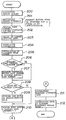
- Fig. 5 is a flowchart of the total display operation of the moving body information. This algorithm is stored in the form of control programs in the ROM of the host computer 9 that is installed in the center control apparatus 1.
- step 100 it is set that the display operation constitutes a loop which permanently continues to work until an end instruction is provided.
- step 101 the position data from the first to n-th moving body terminals 3-1, 3-2, ...., 3-n are taken in.
- step 102 it is judged whether the display mode is "total display". In the “total display” mode, there is displayed the positions of the respective moving bodies over the entire operating area which is a jurisdictional area of the center control apparatus 1. If the judgment result of step 102 is "yes”, the process proceeds to step 103, where a map of the entire operating area is displayed on the display 11. Data of this map is read out from the disk memory 13 shown in Fig. 2. Then, in step 104, the positions of the respective moving bodies are displayed on the display 11, that is, superimposed on the map.
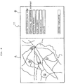
- Fig. 6 shows an example of a picture to appear on the display 11.
- a displayed picture consists of a map display area A on the left side and a guidance display area B on the right side.
- Guidance for operators is displayed in the guidance display area B.
- step 105 while making control to display positions of the respective moving bodies on the map, the host computer 9 executes a waiting process (step 105) for the communication with the first to n-th moving body terminals 3-1, 3-2, ...., 3-n. Then, the process returns to step 101 to repeat the above.
- step 106 for judging whether the mode of displaying a position of each moving body is to be effected. If the judgment result of step 106 is "yes”, the process goes to step 107 for displaying a map of an area around the location of a specified moving body on the basis of position data of that moving body. Then, in step 108, the position and related data of the specified moving body are superimposed on the map.
- step 109 it is judged whether the " "locus display” mode of displaying a movement history, i.e., a locus of a moving body under attention is to be effected. If the judgment is affirmative, the process goes to step 110, where movement history data representing present and past positions of the moving body under attention are read out from the RAM of the host computer 9, and continuous locus data is generated. Then, the process goes to step 111, where a movement locus of the moving body under attention is displayed together with a map.
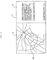
- Fig. 7 shows an example of a picture appearing on the display 11, where the movement locus of the moving body under attention until the present time is indicated by hatching.
- Fig. 8 is a flowchart of searching positions of the moving bodies in such a case.
- a picture as shown in Fig. 9 is first displayed on the display 11.
- the search center data thus input is taken in in step 200.
- the operator inputs through the input console 10 search distance data to specify a search distance, i.e., to define the search area.
- search distance i.e., to define the search area.
- a moving body nearest to the search center may be searched for.
- step 202 a search operation is started with a moving body number set to 1 and a minimum distance, e.g., at 40,000 km.
- the search is conducted by repeating processes of steps 202-209 while the moving body number is started from 1 and sequentially increased by one in step 210.
- Latest position data of a moving body of number 1 is taken in in step 203, subjected to coordinate conversion in step 204, and a distance between the moving body of number 1 and the search center is calculated in step 205.
- step 206 it is judged whether the calculated distance value is smaller than the present minimum distance.
- the judgment result of step 206 should be "yes", and the process goes to step 207.
- the moving body of number 1 is set as a moving body located at a minimum distance position.
- step 206 the judgment of step 206 is made with the distance of the moving body of number 1 as the minimum distance.
- step 208 it is judged whether the subject moving body of number 1 is located within a circle 34 (see Fig. 9) whose center and radius are the search center (step 200) and the search distance (step 201). If the judgment is affirmative, the moving body number 1 is stored in step 209 as search-result data. If, on the other hand, the judgment is negative, the process jumps to step 210, where the moving body number is increased by one to deal with position data of the next moving body of number 2. In the same manner, the processes of steps 202-210 are repeated. When such processes have completed for all the moving bodies, the process goes to step 211. In step 211, the minimum distance data among the stored distance data of the respective moving bodies is extracted. Then, in step 212, the data of the minimum distance moving body (i.e., the moving body closest to the search center) is displayed.
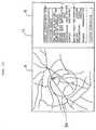
- Fig. 10 shows an example of a displayed picture in which a circle 34 of the search area is defined in the processes of step 202-210 and the moving bodies of numbers 1 and 3 exist within that area.
- the circle 34 indicating the search area and the moving body positions are displayed together with a map in the map display area A, and data related to these moving bodies are displayed in the guidance display area B.
- the respective moving body terminals transmit the position data indicating their present positions to the center control apparatus.
- the center control apparatus displays the present positions of the respective moving bodies such that they are superimposed on a map.
- the movement status of a plurality of moving bodies can be intensively monitored in a real-time basis, to realize efficient operation of the moving bodies.
- a movement history of a specified moving body may be displayed on a map, which makes it possible to monitor the movement status in more detail.
- the present positions of only the moving bodies existing in a specified smaller area within the total operating area may be displayed, which provides closer control of the moving bodies.
Description
- The present invention relates to a remote monitoring and controlling of moving bodies such as humans, automobiles, aircraft and ships. More specifically, the invention relates to the system of the above type which is suitable for intensively controlling a plurality of moving bodies from one location.
- Many companies presently conduct their business activities using automobiles (hereinafter referred to as "moving bodies") such as trucks, hired cars and taxicabs. If a company uses a large number of moving bodies, it may be required, in order to efficiently utilize the moving bodies, to precisely know the operating status of the respective moving bodies and to conduct the transportation management in accordance with the operating status.
- Presently, in most cases, the operation status is known by regular-basis communication from drivers to headquarters (e.g., transportation center) using a telephone, radio communication device, etc., or by drivers' daily reports.
- However, in order to efficiently use the moving bodies, it is preferable to know their operating status on a real-time basis, specifically in such fields as cash transportation, load transportation and police.
- An object of the present invention is to provide a remote monitoring and controlling system of moving bodies, which is capable of efficiency utilizing the moving bodies by intensively monitoring their movement status on a real-time basis in a detailed manner.
- EP-A-0379198 discloses a mobile object navigation system. WO-A-8912835 discloses a road vehicle position monitoring system with central control.
- According to the present invention, there is provided a remote monitoring and controlling system for a plurality of moving bodies, comprising:
- a moving body terminal, at each of the plurality of moving bodies, comprising:
- means for detecting a position of an associated moving body; and
- means for transmitting positional information indicating the detected position; and a center control apparatus comprising:
- means for receiving the positional information;
- means for storing the received positional information of the plurality of moving bodies; and
- control means for producing image information including position data and map data based on the stored positional information; characterised by:
- the center control apparatus including means for displaying, in a total display mode, the positions of the plurality of moving bodies in an entire operating area thereof such that they are superimposed on a map including the entire operating area based on the image information; and
- the position detecting means comprising:
- a GPS receiver (20) for receiving a position determining signal from a GPS satellite, and for producing positional information for the associated moving body based upon the received position determining signal;
- a speed detecting device (22), provided in the associated moving body, for detecting the speed of movement of the associated moving body to produce a speed signal;
- a movement direction detecting device, provided in the associated moving body, for detecting the direction of movement of the associated moving body to produce a direction signal; and
- a data processing device for producing the positional information based on the speed signal and the direction signal.
- In the drawings:-
- Fig. 1 is a block diagram showing the whole construction of a remote monitoring and controlling system according to the present invention;
- Fig. 2 is a block diagram showing the construction of a center control apparatus according to the invention;
- Fig. 3 is a block diagram showing a moving body terminal according to the invention;
- Fig. 4 is a block diagram showing an example of a display;
- Fig. 5 is a flowchart showing a total display operation of moving body information;
- Fig. 6 is a diagram showing an example of a picture appearing on the display in the total display operation;
- Fig. 7 is a diagram showing an example of a picture in which a movement locus of a moving body is displayed;
- Fig. 8 is a flowchart showing an operation of searching positions of moving bodies in a specified area;
- Fig. 9 is a diagram showing an example of a picture for defining the area of searching moving body positions; and
- Fig. 10 is a diagram showing an example of a picture in which results of the position search are displayed.
- Embodiments of the present invention are described hereinafter with reference to the accompanying drawings.
- Fig. 1 is a block diagram of an entire system of remotely monitoring and controlling moving bodies. A
center control apparatus 1 is installed at headquarters which are located at a place suitable for operating the system under consideration. On the other hand, a first moving body terminal 3-1, second moving body terminal 3-2, ...., n-th moving body terminal 3-n are installed on respective moving bodies which move according to their own operating schedules in a geographical area to which the system under consideration is applied. Each of the first to n-th moving body terminals 3-1, 3-1, ...., 3-n detects its own location, for instance, on the basis of a position-determining radio signal which is sent from an artificial satellite 6 and received by aGPS antenna 4, and transmits information on its present location to thecenter control apparatus 1 by radio communication viaantennas center control apparatus 1 displays an image containing a map of the operating area and movement information such as present locations of the respective moving bodies on the basis of the transmitted information on the present locations. - Each of the above units is described below in detail.
- Fig. 2 shows the construction of the
center control apparatus 1. Ahost computer 9 as a main part of thecenter control apparatus 1 controls not only the entirecenter control apparatus 1 but also the display operation according to the invention. Although not shown in Fig. 2, thehost computer 9 can be an ordinary computer including a CPU, a ROM connected to the CPU via a signal bus, a RAM, an I/O port and other parts. The ROM stores control programs for the control of the entirecenter control apparatus 1, control programs for the display operation according to the invention, and other necessary programs. Programs for the display operation and data collection and processing are directly related to the invention, and control algorithm of such programs is described below. - Connected to the
host computer 9, as I/O peripheral devices, are aninput console 10 for entry of necessary data, adisplay 11 for the display operation, and aprinter 12 for hard-copying displayed data. Also connected to thehost computer 9 are a disk memory or CD-ROM 13 for storing collected data and for storing in advance map data etc., and a CMT (cassette magnetic tape)memory 14 for the system back-up etc. Further, amodem 15,communication device 17 andantenna 2 for exchanging data with the first to n-th moving bodies 3-1, 3-2, ...., 3-n are also connected to thehost computer 9. Where communication with the moving bodies is performed via the relay station 7,commercial lines 18 and amodem 16 are employed between the relay station 7 and thehost computer 9. - Fig. 3 shows the construction of the first moving body terminal 3-1. Since the other moving body terminals 3-2, ...., 3-n have the same construction, drawings and descriptions for those are omitted here. The first moving body terminal 3-1 basically acts as a navigation device and a communication device, and its main functions are performed by a
navigation microcomputer 19, which can be an ordinary microcomputer. Although not shown in Fig. 3, thenavigation microcomputer 19 includes a CPU, ROM, RAM, signal bus and I/O port. The navigation function and data communication function are performed in cooperation with peripheral devices (described later) while being controlled by control programs stored in the ROM. - Further, the first moving body terminal 3-1 has a
GPS receiver 20 as a position detecting means. TheGPS receiver 20, connected to thenavigation microcomputer 19, receives a position-determining signal from the artificial satellite 6 by theGPS antenna 4, and provides, based on the received position-determining signal, thenavigation microcomputer 19 with a signal indicating a movement distance and a movement direction of the first moving body. On the other hand, separately from the GPS-based position-determining device, the first moving body terminal 3-1 has an independent position-determining device, which consists of a direction sensor 21 such as a magnetic gyro and aspeed sensor 22 for detecting a vehicle speed from, e.g., a rotational speed of a crank shaft of the moving body. Thenavigation microcomputer 19 performs data processing on the basis of a movement direction signal from the direction sensor 21 and a speed signal from thespeed sensor 22, to detect a present position of the moving body. Although the first moving body 3-1 may have either one of the two position-determining devices, reliability of the position detecting information will be improved by selecting appropriate device in accordance with a variation of a GPS radio signal state and an environment of the moving body. More specifically, the satellite-based device has an advantage of not being affected by the environment conditions, but will not operate correctly, e.g., in a tunnel. Further, the employment of the two devices provides an advantage that position-determining data of one device can be corrected using that of the other device. - The moving body terminal 3-1 has, as an I/O means, an
input console 27 and adisplay 28. Further, it has a CD-ROM drive 24 for a CD-ROM 23 which stores map data etc. necessary for the navigating operation. Amodem 29,communication device 31 andantenna 5 serve to transmit position data of the moving body to thecenter control apparatus 1 and to receive a message therefrom. Themodem 29 operates when communication is performed via the relay station 7. - Fig. 4 shows an example of the
display 11 that is installed in thecenter control apparatus 1. In large-scale transportation systems, it may be the case that the moving bodies are controlled by a plurality of operators. In such a case, it would be convenient that the positional information, map, etc. be displayed on a large screen to share those by the operators, instead of displaying those on individual displays for the respective operators. The large screen may be constructed by projection TV units arranged in matrix form. In this case, if an image is simply enlarged while the pixel density (516 scanning lines in the case of usual CRT displays) is kept unchanged, the enlarged image on thedisplay 11 will become too thin. Therefore, it is required to increase the pixel density. To this end, the original image is divided into a plurality of sub-images corresponding to the respective projection TV units of thedisplay 11, and necessary interpolation is performed. A down-converter 32 converts a computer image signal having non-interlaced scanning and a higher horizontal frequency of 24-70 kHz into an interlaced scanning image signal of an ordinary TV system. A multi-converter 33 divides the resultant signal into image signals for the respective TV units. - Next, a display control operation by the
center control apparatus 1 for the remote monitoring of the respective moving bodies is described. - First, referring to Fig. 1, the total operation of the remote monitoring and controlling system of moving bodies is briefly described. For instance receiving the position-determining radio signal from the artificial satellite 6, each of the first to n-th moving body terminals 3-1, 3-2, ...., 3-n detects its present location, and transmits the present position data through the path of the
antenna 5,antenna 2 andcenter control apparatus 1 or through the path of theantenna 5, antenna 8, relay station 7 andcenter control apparatus 1. Collecting the position data from the first to n-th moving body terminals 3-1, 3-2, ...., 3-n, thecenter control apparatus 1 performs necessary data processing and displays positions of the respective moving bodies. - Fig. 5 is a flowchart of the total display operation of the moving body information. This algorithm is stored in the form of control programs in the ROM of the
host computer 9 that is installed in thecenter control apparatus 1. - Referring to Fig. 5, in
step 100, it is set that the display operation constitutes a loop which permanently continues to work until an end instruction is provided. Then, instep 101, the position data from the first to n-th moving body terminals 3-1, 3-2, ...., 3-n are taken in. Instep 102, it is judged whether the display mode is "total display". In the "total display" mode, there is displayed the positions of the respective moving bodies over the entire operating area which is a jurisdictional area of thecenter control apparatus 1. If the judgment result ofstep 102 is "yes", the process proceeds to step 103, where a map of the entire operating area is displayed on thedisplay 11. Data of this map is read out from thedisk memory 13 shown in Fig. 2. Then, instep 104, the positions of the respective moving bodies are displayed on thedisplay 11, that is, superimposed on the map. Fig. 6 shows an example of a picture to appear on thedisplay 11. - As shown in Fig. 6, a displayed picture consists of a map display area A on the left side and a guidance display area B on the right side. Guidance for operators is displayed in the guidance display area B.
- Returning to Fig. 5, while making control to display positions of the respective moving bodies on the map, the
host computer 9 executes a waiting process (step 105) for the communication with the first to n-th moving body terminals 3-1, 3-2, ...., 3-n. Then, the process returns to step 101 to repeat the above. - Where the judgment result of
step 102 is "no", the process goes to step 106 for judging whether the mode of displaying a position of each moving body is to be effected. If the judgment result ofstep 106 is "yes", the process goes to step 107 for displaying a map of an area around the location of a specified moving body on the basis of position data of that moving body. Then, instep 108, the position and related data of the specified moving body are superimposed on the map. - Where the judgment result of
step 106 is "no", the process goes to step 109. Instep 109, it is judged whether the " "locus display" mode of displaying a movement history, i.e., a locus of a moving body under attention is to be effected. If the judgment is affirmative, the process goes to step 110, where movement history data representing present and past positions of the moving body under attention are read out from the RAM of thehost computer 9, and continuous locus data is generated. Then, the process goes to step 111, where a movement locus of the moving body under attention is displayed together with a map. Fig. 7 shows an example of a picture appearing on thedisplay 11, where the movement locus of the moving body under attention until the present time is indicated by hatching. - The above total display operation is for the case of displaying positions of the moving bodies in the entire operating area, i.e., the jurisdictional area of the
center control apparatus 1. On the other hand, it is often desired that positions of the moving bodies in a particular region of the entire area be known. Fig. 8 is a flowchart of searching positions of the moving bodies in such a case. - Prior to the position search, a picture as shown in Fig. 9 is first displayed on the
display 11. Referring to Fig. 8, when an operator inputs search center data to thehost computer 9 through theinput console 10, the search center data thus input is taken in instep 200. Then, the operator inputs through theinput console 10 search distance data to specify a search distance, i.e., to define the search area. As a modification, where no search distance is specified, a moving body nearest to the search center may be searched for. Next, instep 202, a search operation is started with a moving body number set to 1 and a minimum distance, e.g., at 40,000 km. The search is conducted by repeating processes of steps 202-209 while the moving body number is started from 1 and sequentially increased by one instep 210. Latest position data of a moving body ofnumber 1 is taken in instep 203, subjected to coordinate conversion instep 204, and a distance between the moving body ofnumber 1 and the search center is calculated instep 205. Instep 206, it is judged whether the calculated distance value is smaller than the present minimum distance. At the initial stage where there is no data prior to that of the moving body ofnumber 1, the judgment result ofstep 206 should be "yes", and the process goes to step 207. Instep 207, the moving body ofnumber 1 is set as a moving body located at a minimum distance position. Therefore, for the next moving body ofnumber 2, the judgment ofstep 206 is made with the distance of the moving body ofnumber 1 as the minimum distance. Instep 208, it is judged whether the subject moving body ofnumber 1 is located within a circle 34 (see Fig. 9) whose center and radius are the search center (step 200) and the search distance (step 201). If the judgment is affirmative, the movingbody number 1 is stored instep 209 as search-result data. If, on the other hand, the judgment is negative, the process jumps to step 210, where the moving body number is increased by one to deal with position data of the next moving body ofnumber 2. In the same manner, the processes of steps 202-210 are repeated. When such processes have completed for all the moving bodies, the process goes to step 211. Instep 211, the minimum distance data among the stored distance data of the respective moving bodies is extracted. Then, in step 212, the data of the minimum distance moving body (i.e., the moving body closest to the search center) is displayed. - Fig. 10 shows an example of a displayed picture in which a
circle 34 of the search area is defined in the processes of step 202-210 and the moving bodies ofnumbers circle 34 indicating the search area and the moving body positions are displayed together with a map in the map display area A, and data related to these moving bodies are displayed in the guidance display area B. - As described in the foregoing, according to the invention, the respective moving body terminals transmit the position data indicating their present positions to the center control apparatus. The center control apparatus displays the present positions of the respective moving bodies such that they are superimposed on a map. As a result, the movement status of a plurality of moving bodies can be intensively monitored in a real-time basis, to realize efficient operation of the moving bodies. Further, a movement history of a specified moving body may be displayed on a map, which makes it possible to monitor the movement status in more detail. Further, the present positions of only the moving bodies existing in a specified smaller area within the total operating area may be displayed, which provides closer control of the moving bodies.
Claims (7)
- A remote monitoring and controlling system for a plurality of moving bodies, comprising:a moving body terminal (3-1,...3-N), at each of the plurality of moving bodies, comprising:means (4,20;21,22) for detecting a position of an associated moving body; andmeans (5,29,31) for transmitting positional information indicating the detected position; and a center control apparatus (1) comprising:means (2,15,17;16,18) for receiving the positional information;means (13,14) for storing the received positional information of the plurality of moving bodies; andcontrol means (9) for producing image information including position data and map data based on the stored positional information; characterised by:the center control apparatus (1) including means (11) for displaying, in a total display mode, the positions of the plurality of moving bodies in an entire operating area thereof such that they are superimposed on a map including the entire operating area based on the image information; andthe position detecting means comprising:a GPS receiver (20) for receiving a position determining signal from a GPS satellite, and for producing positional information for the associated moving body based upon the received position determining signal;a speed detecting device (22), provided in the associated moving body, for detecting the speed of movement of the associated moving body to produce a speed signal;a movement direction detecting device (21), provided in the associated moving body, for detecting the direction of movement of the associated moving body to produce a direction signal; anda data processing device (19) for producing the positional information based on the speed signal and the direction signal.
- The system of claim 1, wherein the GPS receiver (20) produces a movement distance signal and a direction signal based on the received position determining signal; andthe position detecting means further comprises:an antenna (4) for receiving the position-determining signal; anda data processing device (19) for producing the positional information of the associated moving body based on the movement distance signal and the direction signal.
- The system of claim 1, wherein the transmitting means is a radio transmitter (5,31) which transmits the positional information in the form of a radio signal, and wherein the receiving means is a radio receiver (2,17) which converts the received positional information into an electrical signal.
- The system of claim 1, wherein the transmitting means is a radio transmitter (5,31) which transmits the positional information in the form of a radio signal, and wherein the receiving means is a receiver (8) for commercial telephone lines connected to a relay station (7).
- The system of claim 1, wherein the control means (9) is arranged to select one of the plurality of moving bodies (3-1,...3-n), and produces the image information including movement history data of the selected moving body, and wherein the displaying means (11) displays, in a locus display mode, a movement history of the selected moving body such that it is superimposed on the map.
- The system of claim 1, wherein the control means (9) is arranged to select one of the plurality of moving bodies (3-1,...3-n), and produces the image data including the map data of a partial map around the position of the selected moving body; and wherein the display means (11) displays, in an individual display mode, the position of the selected moving body such that it is superimposed on the partial map.
- A system according to any of claims 1 to 4 wherein:the control means (9) includes means for searching for part of the plurality of moving bodies existing in a specified area within an entire operating area of the plurality of moving bodies, and for producing image information including position data and map data based on the stored positional information of the part of the plurality of moving bodies; andthe means (11) is arranged to display the positions of the part of the plurality of moving bodies such that they are superimposed on a map including the specified area based on the image information.
Applications Claiming Priority (4)
| Application Number | Priority Date | Filing Date | Title |
|---|---|---|---|
| JP88361/91 | 1991-04-19 | ||
| JP8836191A JPH04319990A (en) | 1991-04-19 | 1991-04-19 | Long-distance monitor control device for mobile body |
| JP3088360A JPH04319989A (en) | 1991-04-19 | 1991-04-19 | Long-distance monitor control device for mobile body |
| JP88360/91 | 1991-04-19 |
Publications (3)
| Publication Number | Publication Date |
|---|---|
| EP0509775A2 EP0509775A2 (en) | 1992-10-21 |
| EP0509775A3 EP0509775A3 (en) | 1993-07-28 |
| EP0509775B1 true EP0509775B1 (en) | 1997-09-03 |
Family
ID=26429755
Family Applications (1)
| Application Number | Title | Priority Date | Filing Date |
|---|---|---|---|
| EP19920303371 Revoked EP0509775B1 (en) | 1991-04-19 | 1992-04-15 | Remote monitoring and controlling system for moving bodies |
Country Status (2)
| Country | Link |
|---|---|
| EP (1) | EP0509775B1 (en) |
| DE (1) | DE69221924T2 (en) |
Cited By (1)
| Publication number | Priority date | Publication date | Assignee | Title |
|---|---|---|---|---|
| US9235972B2 (en) | 1997-01-21 | 2016-01-12 | Pragmatus Mobile LLC | Personal security and tracking system |
Families Citing this family (8)
| Publication number | Priority date | Publication date | Assignee | Title |
|---|---|---|---|---|
| ES2047449B1 (en) * | 1992-06-08 | 1996-11-16 | Servicios Profesionales Y Proy | ELECTRONIC NAVIGATION SYSTEM VIA SATELLITE. |
| FR2705515B1 (en) * | 1993-05-13 | 1995-07-21 | D 3 E Electronique | Telecommunication system between a fixed station and at least one mobile. |
| US5351194A (en) * | 1993-05-14 | 1994-09-27 | World Wide Notification Systems, Inc. | Apparatus and method for closing flight plans and locating aircraft |
| DE4434861A1 (en) | 1994-09-29 | 1996-04-04 | Grundig Emv | Arrangement for securing railway lines |
| GB2298539A (en) * | 1995-02-27 | 1996-09-04 | Richard Deehan | Portable guidance device |
| DE19526494C2 (en) * | 1995-07-20 | 2000-04-27 | Hermann W Kurth | Mobile measuring cell for recording actual value data about the current location of the mobile measuring cell |
| DE19611209C2 (en) * | 1996-03-21 | 1999-05-12 | Industrieanlagen Betriebsges | Method for determining the position of objects, namely mobile exercise participants in a combat exercise |
| CN102495594B (en) * | 2011-11-14 | 2013-08-14 | 武汉理工大学 | Remote monitoring system and method |
Family Cites Families (3)
| Publication number | Priority date | Publication date | Assignee | Title |
|---|---|---|---|---|
| GB8814456D0 (en) * | 1988-06-17 | 1988-08-17 | Cleveland Innovative Technolog | Road vehicle locating system |
| US5025261A (en) * | 1989-01-18 | 1991-06-18 | Sharp Kabushiki Kaisha | Mobile object navigation system |
| JPH04319991A (en) * | 1991-04-19 | 1992-11-10 | Pioneer Electron Corp | Long-distance monitor control device for mobile body |
-
1992
- 1992-04-15 DE DE1992621924 patent/DE69221924T2/en not_active Expired - Fee Related
- 1992-04-15 EP EP19920303371 patent/EP0509775B1/en not_active Revoked
Cited By (1)
| Publication number | Priority date | Publication date | Assignee | Title |
|---|---|---|---|---|
| US9235972B2 (en) | 1997-01-21 | 2016-01-12 | Pragmatus Mobile LLC | Personal security and tracking system |
Also Published As
| Publication number | Publication date |
|---|---|
| DE69221924D1 (en) | 1997-10-09 |
| EP0509775A2 (en) | 1992-10-21 |
| EP0509775A3 (en) | 1993-07-28 |
| DE69221924T2 (en) | 1998-03-12 |
Similar Documents
| Publication | Publication Date | Title |
|---|---|---|
| EP0509776A2 (en) | Remote monitoring and controlling system for moving bodies | |
| EP0509777A2 (en) | Remote monitoring and controlling system for moving bodies | |
| US5548822A (en) | Mobile station monitoring system | |
| US6771969B1 (en) | Apparatus and method for tracking and communicating with a mobile radio unit | |
| EP0494499B1 (en) | System and method for monitoring and reporting out-of-route mileage for long haul trucks | |
| EP1708150A2 (en) | System and method for providing information of states of movement of moving objects, a location data collection system, and a car navigation system | |
| JP4014108B2 (en) | Ship operation monitoring system | |
| JP2002525728A (en) | Method and apparatus for automatic event detection in wireless communication systems | |
| JPH09212797A (en) | Information service device | |
| EP0710941A2 (en) | Navigation system for an automotive vehicle | |
| AU9241398A (en) | A waiting time prediction system | |
| WO1993011443A1 (en) | Method and apparatus for controlling vehicle movements | |
| JP3469930B2 (en) | Mobile multimedia communication system and mobile | |
| US6002345A (en) | Assurance of intercommunication and position recognition between mobile stations with navigation apparatuses | |
| EP0509775B1 (en) | Remote monitoring and controlling system for moving bodies | |
| JPH10307993A (en) | Traffic information collection system | |
| EP1134550A1 (en) | Method for guiding a vehicle using roadside beacons | |
| JP2914485B2 (en) | Vehicle dispatch system | |
| US6434480B1 (en) | Information communications apparatus for vehicle | |
| KR19980068114A (en) | Comprehensive Traffic Information Management System Using Mobile Phone | |
| JP3171025B2 (en) | Travel position display device | |
| JP4201853B2 (en) | Master station control operation support and management method, mobile object positioning method | |
| JPH04319990A (en) | Long-distance monitor control device for mobile body | |
| JPH0765292A (en) | On-vehicle position display device | |
| JPH04319989A (en) | Long-distance monitor control device for mobile body |
Legal Events
| Date | Code | Title | Description |
|---|---|---|---|
| PUAI | Public reference made under article 153(3) epc to a published international application that has entered the european phase |
Free format text: ORIGINAL CODE: 0009012 |
|
| AK | Designated contracting states |
Kind code of ref document: A2 Designated state(s): DE FR GB |
|
| PUAL | Search report despatched |
Free format text: ORIGINAL CODE: 0009013 |
|
| AK | Designated contracting states |
Kind code of ref document: A3 Designated state(s): DE FR GB |
|
| 17P | Request for examination filed |
Effective date: 19940125 |
|
| 17Q | First examination report despatched |
Effective date: 19960116 |
|
| GRAG | Despatch of communication of intention to grant |
Free format text: ORIGINAL CODE: EPIDOS AGRA |
|
| GRAH | Despatch of communication of intention to grant a patent |
Free format text: ORIGINAL CODE: EPIDOS IGRA |
|
| GRAH | Despatch of communication of intention to grant a patent |
Free format text: ORIGINAL CODE: EPIDOS IGRA |
|
| GRAA | (expected) grant |
Free format text: ORIGINAL CODE: 0009210 |
|
| AK | Designated contracting states |
Kind code of ref document: B1 Designated state(s): DE FR GB |
|
| REF | Corresponds to: |
Ref document number: 69221924 Country of ref document: DE Date of ref document: 19971009 |
|
| ET | Fr: translation filed | ||
| PG25 | Lapsed in a contracting state [announced via postgrant information from national office to epo] |
Ref country code: GB Free format text: LAPSE BECAUSE OF NON-PAYMENT OF DUE FEES Effective date: 19980415 |
|
| PLBQ | Unpublished change to opponent data |
Free format text: ORIGINAL CODE: EPIDOS OPPO |
|
| PLBI | Opposition filed |
Free format text: ORIGINAL CODE: 0009260 |
|
| PLBF | Reply of patent proprietor to notice(s) of opposition |
Free format text: ORIGINAL CODE: EPIDOS OBSO |
|
| 26 | Opposition filed |
Opponent name: MANNESMANN AG Effective date: 19980603 |
|
| GBPC | Gb: european patent ceased through non-payment of renewal fee |
Effective date: 19980415 |
|
| PG25 | Lapsed in a contracting state [announced via postgrant information from national office to epo] |
Ref country code: DE Free format text: LAPSE BECAUSE OF NON-PAYMENT OF DUE FEES Effective date: 19990202 |
|
| REG | Reference to a national code |
Ref country code: FR Ref legal event code: ST |
|
| RDAH | Patent revoked |
Free format text: ORIGINAL CODE: EPIDOS REVO |
|
| RDAG | Patent revoked |
Free format text: ORIGINAL CODE: 0009271 |
|
| STAA | Information on the status of an ep patent application or granted ep patent |
Free format text: STATUS: PATENT REVOKED |
|
| 27W | Patent revoked |
Effective date: 19990823 |
|
| PG25 | Lapsed in a contracting state [announced via postgrant information from national office to epo] |
Ref country code: FR Free format text: LAPSE BECAUSE OF NON-PAYMENT OF DUE FEES Effective date: 19980430 |