EP0514174A1 - Cable closure including grommet having enhanced sealing capability - Google Patents
Cable closure including grommet having enhanced sealing capability Download PDFInfo
- Publication number
- EP0514174A1 EP0514174A1 EP92304362A EP92304362A EP0514174A1 EP 0514174 A1 EP0514174 A1 EP 0514174A1 EP 92304362 A EP92304362 A EP 92304362A EP 92304362 A EP92304362 A EP 92304362A EP 0514174 A1 EP0514174 A1 EP 0514174A1
- Authority
- EP
- European Patent Office
- Prior art keywords
- grommet
- passageway
- slit
- portions
- ridge
- Prior art date
- Legal status (The legal status is an assumption and is not a legal conclusion. Google has not performed a legal analysis and makes no representation as to the accuracy of the status listed.)
- Granted
Links
Images


Classifications
-
- G—PHYSICS
- G02—OPTICS
- G02B—OPTICAL ELEMENTS, SYSTEMS OR APPARATUS
- G02B6/00—Light guides; Structural details of arrangements comprising light guides and other optical elements, e.g. couplings
- G02B6/44—Mechanical structures for providing tensile strength and external protection for fibres, e.g. optical transmission cables
- G02B6/4439—Auxiliary devices
- G02B6/444—Systems or boxes with surplus lengths
- G02B6/4441—Boxes
- G02B6/4446—Cable boxes, e.g. splicing boxes with two or more multi fibre cables
-
- G—PHYSICS
- G02—OPTICS
- G02B—OPTICAL ELEMENTS, SYSTEMS OR APPARATUS
- G02B6/00—Light guides; Structural details of arrangements comprising light guides and other optical elements, e.g. couplings
- G02B6/44—Mechanical structures for providing tensile strength and external protection for fibres, e.g. optical transmission cables
- G02B6/4401—Optical cables
- G02B6/4415—Cables for special applications
- G02B6/4427—Pressure resistant cables, e.g. undersea cables
- G02B6/4428—Penetrator systems in pressure-resistant devices
-
- G—PHYSICS
- G02—OPTICS
- G02B—OPTICAL ELEMENTS, SYSTEMS OR APPARATUS
- G02B6/00—Light guides; Structural details of arrangements comprising light guides and other optical elements, e.g. couplings
- G02B6/44—Mechanical structures for providing tensile strength and external protection for fibres, e.g. optical transmission cables
- G02B6/4439—Auxiliary devices
- G02B6/444—Systems or boxes with surplus lengths
- G02B6/4441—Boxes
- G02B6/4442—Cap coupling boxes
- G02B6/4444—Seals
-
- G—PHYSICS
- G02—OPTICS
- G02B—OPTICAL ELEMENTS, SYSTEMS OR APPARATUS
- G02B6/00—Light guides; Structural details of arrangements comprising light guides and other optical elements, e.g. couplings
- G02B6/44—Mechanical structures for providing tensile strength and external protection for fibres, e.g. optical transmission cables
- G02B6/4439—Auxiliary devices
- G02B6/4471—Terminating devices ; Cable clamps
-
- H—ELECTRICITY
- H02—GENERATION; CONVERSION OR DISTRIBUTION OF ELECTRIC POWER
- H02G—INSTALLATION OF ELECTRIC CABLES OR LINES, OR OF COMBINED OPTICAL AND ELECTRIC CABLES OR LINES
- H02G15/00—Cable fittings
- H02G15/013—Sealing means for cable inlets
Definitions
- This invention relates to a cable closure which includes at least one grommet having enhanced sealing capability.
- a closure where two ends of a cable such as a telecommunications cable are spliced together, the splice area is ordinarily housed within a protective cover known as a closure.
- a protective cover known as a closure.
- the integrity of seals which are used to restrict moisture ingress is important especially because of transmission parameters which are readily effected by changes in the moisture content within the cable.
- Such closures often have included cylindrical covers with one or more longitudinal joints and end plates that surround incoming and outgoing cables and that form seals with the covers.
- An example of a prior art closure is shown in U.S. Pat. No. 4,927,227.
- a grommet which is used in splice cases to provide a seal about an entering or exiting cable.
- the grommet comprises a unitary elastomeric body having a slit along a split line to allow a cable to be inserted into a cable receiving passageway within the grommet.
- Each passageway is defined by an interior sidewall from which a plurality of longitudinally spaced circumferential ridges extend.
- each ridge has an axis of projection which forms an oblique angle with respect to an axis of the passageway and is sufficiently elongated in longitudinal cross section so as to be capable of flexing with respect to the axis of projection during cable insertion and enlarging its opening diameter to accommodate and form a radial seal about a cable being inserted.
- the end plate may be formed to include two portions which are separated along lines which extend through the cable openings. Prior to assembly of the end plate portions, grommets are disposed in the openings in one portion and then the other portion assembled thereto. However, there are some closures in which the end plate is unipartite in which case the grommet or grommets are forced into the opening or openings in the end plate. When this is done, portions of each grommet adjacent to its split line may become offset from each other.
- a closure as set forth in claim 1.
- a grommet included in the closure of claim 1 is set forth in claim 7.
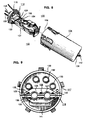
- FIG. 1 there is shown a closure which is designated generally by the numeral 20, and a cable splice support assembly 22 in which optical fibers (not shown), for example, are spliced and/or stored and a cover 23.
- the cover 23 is cylindrically shaped and includes an open end 25 and a closed end 27.
- the cable splice support assembly 22 is inserted into the open end 25 of the cover and moved toward the closed end.
- the closure 20 can accommodate additional cables to be spliced or can be used to store optical fibers for future splicing to branch cables.
- the cable splicing support assembly 22 includes a cable entry portion 30 and optical splice support means 32.
- the cable entry portion 30 may include two spaced end plates 34 and 36, each of which is disc-shaped with the end plate 34 being referred to as an outer end plate and the end plate 36 being referred to as an inner end plate.
- Each of the end plates 34 and 36 is made preferably of a molded plastic, glass-reinforced polypropylene.
- the two end plates 34 and 36 are held in assembled relationship spaced apart by a central stud 38 and three circumferentially disposed standoffs 39-39 which are molded integrally with the inner end plate 36.
- bonding facilities designated generally by the numeral 40, which are used to ground portions of the cables.
- Each of the end plates is also provided with oval shaped openings.
- three openings are provided with those in the outer end plate 34 being designated 41, 43 and 45 and with those in the inner end plate 36 being designated 47, 48 and 49. Openings in the end plate 34 are aligned with associated ones of the openings in the end plate 36.
- the opening 41 is aligned with the opening 47, 45 and 48 and 43 with 49.
- a grommet 50 Disposed in the opening 43 is a grommet 50 (see FIGS. 1, 2, and 3).
- the grommet 50 shown in the drawing includes two passageways 52-52 through which are destined to extend the cables 28 and 29 to be spliced.
- a grommet 54 which is aligned with the grommet 50 and which includes two passageways 56-56 is disposed in the opening 49.
- Two cables to be spliced are destined to extend through the passageways 52-52 and 56-56 of the aligned grommets 50 and 54.
- Each of the openings 47, 48 and 49 of the inner end plate 36 has a rim thereabout on the inner side of the inner end plate. In this way, the grommets in the inner end plate are prevented from moving through the inner end plate.
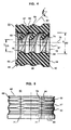
- the sealing grommet 50 (see FIGS. 3, 4 and 5), which includes a unitary body 60 preferably is molded from an elastomeric material such as urethane rubber, for example, includes an inner end face 62, an outer end face 64, and a substantially longitudinally-extending outer Surface portion 66. Adjacent to the end face 62 is provided a radial shoulder 68. Extending from the outer surface portion 66 are a plurality of annular ribs 69-69 having grooves 67-67 therebetween. The ribs 69-69 of each grommet are designed to seat in an opening of and to form a seal with a wall of the end plate which defines an opening in which the grommet is disposed.
- an elastomeric material such as urethane rubber
- each grommet 50 is provided with one or more passageways 52-52.
- each passageway 52 has associated therewith a longitudinally-extending slit 71 in the grommet body which extends radially from the passageway to the outer surface portion 66 to provide access for sliding a portion of each cable 28, 29 into a passageway 52.
- Each slit 71 is associated with and extends parallel to a longitudinal axis 73 (see FIG. 4) of an associated passageway which extends through each grommet. Further, each slit 71 allows adjacent portions of the body of the grommet which are adjacent to and define the slit to be moved apart to expose the passageway.
- each slitted passageway 52 is defined by a cylindrical interior sidewall 72 having a nominal diameter D SW which is larger than the diameter of any cable expected to be inserted. Also, the passageway is defined by a plurality of longitudinally spaced circumferential ridges 74-74 defining substantially circular openings 76-76 each normally having a diameter D SR which is smaller than the expected diameter of any cable 28,29 to be inserted.
- each ridge 74 is angularly disposed toward the inner grommet face 62 (see FIG. 4) and has a longitudinal cross section having an axis of projection 82 which forms an oblique angle ⁇ with respect to the axis 73 of the associated passageway 52.
- the axis 73 of the passageway 52 is also the axis of the interior sidewall 72.
- Each ridge 74 also is sufficiently elongated for a substantial portion of its periphery so as to be capable of flexing with respect to its axis of projection 82 along the substantial portion. Further, an end portion 83 of each ridge 74 in longitudinal cross section is rounded.
- each ridge 74 In order to engage sealingly a cable, each ridge 74 varies in projected length from the interior sidewall 72 along its circumference. The change in projected length along the circumference is gradual for each ridge 74. Also, each ridge 74 forms a stub-like portion 86 (see FIG. 4) in the vicinity of the slit 71 which is substantially inflexible. In the preferred embodiment, each ridge 74 in the slitted passageway 52 is elongated and flexible for at least 270 degrees of its circumference.
- each ridge 74 is capable of flexing as needed to enlarge its opening 76 during cable insertion.
- each ridge 74 is substantially incapable of flexing and can deform only slightly under compression in the radial direction.
- each ridge 74 in the vicinity of the slit 71 ensures substantial overlap and hence longitudinal alignment of edge portions 84-84 (see also FIG. 6) on each ridge 74 at the slit 71 when the slit closes after insertion of a portion of a cable into the associated passageway. This helps to ensure substantial circumferential surface continuity in each ridge 74 for achieving an effective radial seal about an inserted cable portion.
- the slit 71 is longitudinally extending and the ridges 74-74 are longitudinally aligned with one another so that an imaginary straight line 87 substantially contains the centers of the openings 76.
- This imaginary line 87 is offset radially though parallel with respect to the axis 73 of the passageway 52.
- the ridge shown in FIG. 3 is most elongated along its circumference at a point diametrically opposite to the slit 71 in the passageway 52 and most shortened or stub-like at the slit 71.
- the slit 71 can actually extend diagonally into a passageway rather than as is shown, in which case the centers of the openings 76-76 still would be contained in an imaginary curved line, still not coincident with the axis 73.
- sealing compound may be applied along the longitudinal slits 71-71 before insertion of the cables 28,29 to ensure an effective moisture tight seal along the slits.
- the grommet 50 When the grommet 50 is inserted into an opening in the unitary end plate, the grommet is compressed radially inward supplying forces on the grommet 50 to help ensure that the slits 71-71 close completely.
- a sealing compound also may be applied to the ridges 74-74 to ease cable insertion.
- the grommet 50 includes provisions for causing at least portions of opposing ridge and rib portions adjacent to a slit 71 to overlap notwithstanding the application of forces which tend to cause offset of body portions of the grommet. This is accomplished as shown in the preferred embodiment by increasing the width of each ridge 74 (see FIGS. 4 and 6) and ribs (see FIGS. 2, 4, 5, 6 and 7) as measured in a direction parallel to the axis 73. As is seen in the drawing, each ridge 74 has a portion 90 adjacent to a slit 71 which is substantially more wide than throughout the remainder of its periphery. As a result, when offset in portions adjacent to a slit 71 occurs such as is shown in FIG. 7, there is sufficient width so that at least portions of each ridge 74 which face each other across the slit 71 remain overlapped.
- each rib 69 adjacent to a slit 71 has a portion 94 which is increased in width over the width of other portions which are not adjacent to a slit.
- the ridges 74-74 at least some overlap of the opposing portions 94-94 will be preserved notwithstanding any offset from expected forces (see FIG. 7).
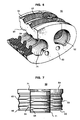
- a cable closure 100 in another embodiment of this invention, includes a splicing termination assembly 102 in which fibers are spliced and/or stored and a cover 104.
- the cover is cylindrically shaped and includes an open end 106 and a closed end 108.
- An axis 112 of the closure extends from the open end 106 of the cover to the closed end 108.
- the cable splicing termination assembly is inserted into the open end 106 of the cover and moved toward the closed end.
- the cable splicing termination assembly 102 includes a cable entry portion 114.
- the cable entry portion 114 includes an end plate assembly 116 a portion of which is disc-shaped.
- the end plate assembly 116 preferably is made of a molded, glass-reinforced plastic material.
- Each end plate assembly 116 includes two portions 117 and 118 (see FIG. 9).
- the portion 117 includes a partially circular flange 120, an outwardly projecting portion 122 and an inwardly projecting portion 124 (see also FIGS. 8 and 10).
- the outwardly projecting portion 122 includes a housing portion 126 having an extension which is designated generally by the numeral 128.
- the extension 128 includes two semi-circular conduits 127-127 which are disposed between landings 129-129 of the extension. Each of the landings 129-129 is provided with a threaded opening 125.
- the inwardly extending portion 124 includes a housing portion 130 from which extends a landing portion 131 comprising spaced ears.
- each of the openings 132-132 is adapted to allow a predetermined drop cable to extend therethrough.
- the end plate assembly 116 also includes a portion 118.
- the portion 118 includes an arcuately shaped flange 141 (see FIGS. 9 and 10) having inner and outer portions 143 and 145, respectively, projecting therefrom.
- the inner portion 143 includes a housing portion 147 which includes a post 148 disposed therein and from which a threaded stud 149 extends upwardly.
- the inner portion 143 includes three spaced ears 151-151 projecting inwardly longitudinally of the closure. Each ear 151 includes an opening 153 therein.
- the openings 153-153 are aligned with threaded openings 155-155 (see FIG. 8) which are formed in the ears of the landing 131.
- Bolts 154-154 are inserted through openings in the cable splice support assembly 102 and through the openings 153-153 and turned into the threaded openings 155-155 of the ears to secure the cable splice support assembly to the end plate assembly 116.
- the outer portion 145 (see FIG.
- each two ears 156-156 includes three spaced ears 156-156 each having an aperture 157 therein. Disposed between each two ears 156-156 is an arcuately formed surface 159 which when the portions 117 and 118 are assembled together cooperates with an arcuately shaped surface of the outwardly projecting portion of the upper portion 117 to provide a conduit for distribution cables 158-158 (see FIG. 8) to be spliced. Also, when the portions 117 and 118 are assembled together, the apertures 157-157 of the outer portion of the portion 1 18 become aligned with the threaded openings in the outwardly projecting portion of the portion 117 so that bolts may be used to secure together the two outwardly extending portions.
- a gasket 160 (see FIG. 10) is disposed between the portions 117 and 118 of the end plate assembly to provide a seal between those two portions when assembled together and about the distribution cables which extend into the end plate assembly and about cable cores which extend out of the cable end plate assembly and farther into the closure.
- Different gaskets may be used to accommodate different cable sizes through the portions of the gaskets which are disposed in engagement with the arcuately formed surfaces of the housing portions.
- Shim washers (not shown) may be disposed over the threaded stud 149, depending on the size of cables used, in order to keep the cable cores centered within the openings in the interior housing portions.
- Other portions of the closure 100 are disclosed in Application Serial No. 07/673,880 which was filed on March 22, 1991 in the names of G. S. Cobb, et al.
- the gasket 160 includes four grommets 162-162. Each of the grommets 162-162 is disposed in one of the conduits in the portions 122 and 124. Further each grommet includes a passageway 164 for receiving a portion of a cable.
- each grommet In order to insure sealing contact between the wall of the end plate which defines each opening and each grommet 162, an outer portion of each grommet is provided with ribs 171-171. When a grommet is disposed in an end plate opening, the ribs 171-171 thereof engage the wall which defines the opening to establish sealing contact. Should offset occur in the grommet 162 between portions adjacent to a slit 173 along a split line, the opposing portions of each rib may be offset sufficiently to allow moisture or water to move therepast.
- the width of portions of the ribs 171-171, as was done with the ribs 69-69, adjacent to each slit 173 is increased to provide portions 175-175 (see FIG. 10) adjoining each slit.
- the increase is such that for any expected offset, there will exist overlap between at least portions of the portions of the ribs adjacent the split lines.
- a grommet 180 includes two slits 182-182. Each slit of the grommet 180 rather than a straight line parallel to a longitudinal axis of the cable is formed in a zigzag configuration comprising a plurality of segments. As a result, forces applied to the cable which extends through the grommet or to the grommet are not effective to offset in a direction parallel to a longitudinal axis 184 the portions of the grommet adjacent to the slit.
Abstract
Description
- This invention relates to a cable closure which includes at least one grommet having enhanced sealing capability.
- Where two ends of a cable such as a telecommunications cable are spliced together, the splice area is ordinarily housed within a protective cover known as a closure. The integrity of seals which are used to restrict moisture ingress is important especially because of transmission parameters which are readily effected by changes in the moisture content within the cable. Such closures often have included cylindrical covers with one or more longitudinal joints and end plates that surround incoming and outgoing cables and that form seals with the covers. An example of a prior art closure is shown in U.S. Pat. No. 4,927,227.
- In U.S. Pat. No. 4,361,721, there is disclosed a grommet which is used in splice cases to provide a seal about an entering or exiting cable. The grommet comprises a unitary elastomeric body having a slit along a split line to allow a cable to be inserted into a cable receiving passageway within the grommet. Each passageway is defined by an interior sidewall from which a plurality of longitudinally spaced circumferential ridges extend. For a substantial portion of its circumference, each ridge has an axis of projection which forms an oblique angle with respect to an axis of the passageway and is sufficiently elongated in longitudinal cross section so as to be capable of flexing with respect to the axis of projection during cable insertion and enlarging its opening diameter to accommodate and form a radial seal about a cable being inserted.
- Despite such provision as the aforementioned grommet, moisture continues to be observed within closures. Because of the slit in the grommet which allows access to the opening therethrough to facilitate insertion of a cable, portions of the grommet on each side of the slit may become offset from each other as a result of forces being applied to the cable or to the closure. With those portions offset from each other, the portions of the ridges which define the cable opening and which are adjacent to the slit become offset, forming a path therebetween along which gas and/or moisture may travel.
- Offset may come about in another way. In some closures, the end plate may be formed to include two portions which are separated along lines which extend through the cable openings. Prior to assembly of the end plate portions, grommets are disposed in the openings in one portion and then the other portion assembled thereto. However, there are some closures in which the end plate is unipartite in which case the grommet or grommets are forced into the opening or openings in the end plate. When this is done, portions of each grommet adjacent to its split line may become offset from each other.
- What is needed and what seemingly is not available in the prior art is a cable closure which includes a grommet that maintains its sealing capability notwithstanding the application of expected forces thereto. The sought after grommet should be relatively easy to manufacture and should continue to provide a seal about a cable extending therethrough despite the application of forces which tend to offset portions of the grommet adjacent to the split line.
- According to the invention, there is provided a closure as set forth in claim 1. A grommet included in the closure of claim 1 is set forth in claim 7.
-
- FIG. 1 is a perspective view of a closure of this invention which includes at least one grommet having enhanced sealing capability;
- FIG. 2 is a perspective view of a grommet which is included in the closure of FIG. 1;
- FIG. 3 is an end view of the grommet of FIG. 2;
- FIG. 4 is a side elevational view in section of the grommet of FIG. 3 taken along lines 4-4 thereof;
- FIG. 5 is a plan view of the grommet of FIG. 3;
- FIG. 6 is a perspective view of the grommet of FIG. 2 broken away to show a perspective view of a passageway;
- FIG. 7 is a plan view of the grommet of FIG. 3 after offset of portions thereof has been caused by the application of forces to the grommet;
- FIG. 8 is a perspective view- of another closure;
- FIG. 9 is an end view of the closure of FIG. 8;
- FIG. 10 is a perspective view of a portion of the closure of FIG. 8 to show a sealing arrangement between portions of the closure; and
- FIG. 11 is a plan view of an alternative embodiment of a grommet of this invention.
- Referring now to FIG. 1, there is shown a closure which is designated generally by the
numeral 20, and a cablesplice support assembly 22 in which optical fibers (not shown), for example, are spliced and/or stored and acover 23. Thecover 23 is cylindrically shaped and includes anopen end 25 and a closedend 27. In order to assemble cable splicework, the cablesplice support assembly 22 is inserted into theopen end 25 of the cover and moved toward the closed end. Whereas the following description describes the splicing of twocables 28 and 29 (see FIG. 2), it should be appreciated that theclosure 20 can accommodate additional cables to be spliced or can be used to store optical fibers for future splicing to branch cables. - As also can be seen in FIG. 1, the cable
splicing support assembly 22 includes acable entry portion 30 and optical splice support means 32. Thecable entry portion 30 may include two spacedend plates end plate 34 being referred to as an outer end plate and theend plate 36 being referred to as an inner end plate. Each of theend plates end plates central stud 38 and three circumferentially disposed standoffs 39-39 which are molded integrally with theinner end plate 36. Disposed between the end plates are bonding facilities, designated generally by thenumeral 40, which are used to ground portions of the cables. - Each of the end plates is also provided with oval shaped openings. In the embodiment shown in FIG. 1, three openings are provided with those in the
outer end plate 34 being designated 41, 43 and 45 and with those in theinner end plate 36 being designated 47, 48 and 49. Openings in theend plate 34 are aligned with associated ones of the openings in theend plate 36. The opening 41 is aligned with the opening 47, 45 and 48 and 43 with 49. - Disposed in the
opening 43 is a grommet 50 (see FIGS. 1, 2, and 3). Thegrommet 50 shown in the drawing includes two passageways 52-52 through which are destined to extend thecables grommet 54 which is aligned with thegrommet 50 and which includes two passageways 56-56 is disposed in the opening 49. Two cables to be spliced are destined to extend through the passageways 52-52 and 56-56 of the alignedgrommets openings inner end plate 36 has a rim thereabout on the inner side of the inner end plate. In this way, the grommets in the inner end plate are prevented from moving through the inner end plate. - Unless it known from the outset that more than two cables are to be spliced in the
closure 20, the other two sets of aligned openings in the end plates are provided with dummy plugs 58-58. Advantageously, as more cable needs to be spliced in theclosure 20, one or both of the dummy plugs is removed and replaced with a pair or pairs of grommets identical to thegrommets - The sealing grommet 50 (see FIGS. 3, 4 and 5), which includes a
unitary body 60 preferably is molded from an elastomeric material such as urethane rubber, for example, includes aninner end face 62, anouter end face 64, and a substantially longitudinally-extendingouter Surface portion 66. Adjacent to theend face 62 is provided aradial shoulder 68. Extending from theouter surface portion 66 are a plurality of annular ribs 69-69 having grooves 67-67 therebetween. The ribs 69-69 of each grommet are designed to seat in an opening of and to form a seal with a wall of the end plate which defines an opening in which the grommet is disposed. - For use with a unitary end plate, forces are applied to the
grommet 50 to cause it to become disposed in the opening 43 (see FIG. 1). As thegrommet 50 becomes disposed in theopening 43 with theend face 64 aligned with an outer surface of the end plate, theshoulder 68 which was compressed during insertion returns to its configuration shown in FIG. 4 and seats against an inner surface of theouter end plate 34. To help ensure an effective seal, sealing compound also may be applied to the ribs 69-69 so that voids between the ribs and annular grooves therebetween are filled. - As mentioned hereinbefore, each
grommet 50 is provided with one or more passageways 52-52. As seen in FIGS. 2 and 3, eachpassageway 52 has associated therewith a longitudinally-extendingslit 71 in the grommet body which extends radially from the passageway to theouter surface portion 66 to provide access for sliding a portion of eachcable passageway 52. Each slit 71 is associated with and extends parallel to a longitudinal axis 73 (see FIG. 4) of an associated passageway which extends through each grommet. Further, each slit 71 allows adjacent portions of the body of the grommet which are adjacent to and define the slit to be moved apart to expose the passageway. This allows a craftsperson to move the grommet over a portion of a cable. A cable is inserted by separating the portions which define apassageway 52 at the split line and pushing the cable transversely into thepassageway 52. Afterwards, the craftsperson releases the grommet portions so that they can return to their unmoved positions to complete the encirclement of the cable portion. - Referring again to FIGS. 2, 3 and 4, it can be seen that each
slitted passageway 52 is defined by a cylindricalinterior sidewall 72 having a nominal diameter DSW which is larger than the diameter of any cable expected to be inserted. Also, the passageway is defined by a plurality of longitudinally spaced circumferential ridges 74-74 defining substantially circular openings 76-76 each normally having a diameter DSR which is smaller than the expected diameter of anycable - For a substantial portion of its circumference, each
ridge 74 is angularly disposed toward the inner grommet face 62 (see FIG. 4) and has a longitudinal cross section having an axis ofprojection 82 which forms an oblique angle β with respect to theaxis 73 of the associatedpassageway 52. In the preferred embodiment, theaxis 73 of thepassageway 52 is also the axis of theinterior sidewall 72. Eachridge 74 also is sufficiently elongated for a substantial portion of its periphery so as to be capable of flexing with respect to its axis ofprojection 82 along the substantial portion. Further, anend portion 83 of eachridge 74 in longitudinal cross section is rounded. - In order to engage sealingly a cable, each
ridge 74 varies in projected length from theinterior sidewall 72 along its circumference. The change in projected length along the circumference is gradual for eachridge 74. Also, eachridge 74 forms a stub-like portion 86 (see FIG. 4) in the vicinity of theslit 71 which is substantially inflexible. In the preferred embodiment, eachridge 74 in theslitted passageway 52 is elongated and flexible for at least 270 degrees of its circumference. - For the substantial portion where each
ridge 74 is sufficiently elongated to flex about its axis ofprojection 82, theridge 74 is capable of flexing as needed to enlarge itsopening 76 during cable insertion. However, in the vicinity of theslit 71, eachridge 74 is substantially incapable of flexing and can deform only slightly under compression in the radial direction. - The inflexibility of each
ridge 74 in the vicinity of theslit 71 ensures substantial overlap and hence longitudinal alignment of edge portions 84-84 (see also FIG. 6) on eachridge 74 at theslit 71 when the slit closes after insertion of a portion of a cable into the associated passageway. This helps to ensure substantial circumferential surface continuity in eachridge 74 for achieving an effective radial seal about an inserted cable portion. - In the
passageway 52 in the illustrative embodiment, theslit 71 is longitudinally extending and the ridges 74-74 are longitudinally aligned with one another so that an imaginarystraight line 87 substantially contains the centers of theopenings 76. Thisimaginary line 87 is offset radially though parallel with respect to theaxis 73 of thepassageway 52. Hence, only oneridge 74 can be seen in FIG. 3. As is representative of the other ridges 74-74, the ridge shown in FIG. 3 is most elongated along its circumference at a point diametrically opposite to theslit 71 in thepassageway 52 and most shortened or stub-like at theslit 71. - It is apparent that the
slit 71 can actually extend diagonally into a passageway rather than as is shown, in which case the centers of the openings 76-76 still would be contained in an imaginary curved line, still not coincident with theaxis 73. - During installation of a
grommet 50 having slitted passageways 52-52, sealing compound may be applied along the longitudinal slits 71-71 before insertion of thecables grommet 50 is inserted into an opening in the unitary end plate, the grommet is compressed radially inward supplying forces on thegrommet 50 to help ensure that the slits 71-71 close completely. A sealing compound also may be applied to the ridges 74-74 to ease cable insertion. - During installation and during use of the closure, forces are caused to be applied to the grommet which, undesirably, cause portions of the
body 60 adjacent to each slit 71 to shift relative to each other as shown in FIG. 7. This causes an offset between a portion of aridge 74 and arib 69 on one side of the slit from a previously aligned opposing portion of the same ridge and rib on the other side of the slit. Each ridge and rib for purposes of sealing in engagement with a cable portion need not be very wide. However, if the ridge is provided with a width sufficient only to resist flexing, the opposing portions at a slit line may become so offset that a path for moisture is established. - In order to overcome this, the
grommet 50 includes provisions for causing at least portions of opposing ridge and rib portions adjacent to aslit 71 to overlap notwithstanding the application of forces which tend to cause offset of body portions of the grommet. This is accomplished as shown in the preferred embodiment by increasing the width of each ridge 74 (see FIGS. 4 and 6) and ribs (see FIGS. 2, 4, 5, 6 and 7) as measured in a direction parallel to theaxis 73. As is seen in the drawing, eachridge 74 has aportion 90 adjacent to aslit 71 which is substantially more wide than throughout the remainder of its periphery. As a result, when offset in portions adjacent to aslit 71 occurs such as is shown in FIG. 7, there is sufficient width so that at least portions of eachridge 74 which face each other across theslit 71 remain overlapped. - The ribs 69-69 on the outer surface of the grommet are provided with a similar structure. As is seen in FIG. 5, for example, each
rib 69 adjacent to aslit 71 has aportion 94 which is increased in width over the width of other portions which are not adjacent to a slit. Again, as with the ridges 74-74, at least some overlap of the opposing portions 94-94 will be preserved notwithstanding any offset from expected forces (see FIG. 7). - In another embodiment of this invention, a cable closure 100 (see FIG. 8) includes a
splicing termination assembly 102 in which fibers are spliced and/or stored and acover 104. The cover is cylindrically shaped and includes anopen end 106 and aclosed end 108. Anaxis 112 of the closure extends from theopen end 106 of the cover to theclosed end 108. In order to assemble the cablesplicing termination assembly 102 with thecover 104, the cable splicing termination assembly is inserted into theopen end 106 of the cover and moved toward the closed end. - As also can be seen in FIG. 8, the cable
splicing termination assembly 102 includes acable entry portion 114. Thecable entry portion 114 includes an end plate assembly 116 a portion of which is disc-shaped. Theend plate assembly 116 preferably is made of a molded, glass-reinforced plastic material. - Each
end plate assembly 116 includes twoportions 117 and 118 (see FIG. 9). Theportion 117 includes a partiallycircular flange 120, an outwardly projectingportion 122 and an inwardly projecting portion 124 (see also FIGS. 8 and 10). The outwardly projectingportion 122 includes ahousing portion 126 having an extension which is designated generally by the numeral 128. Theextension 128 includes two semi-circular conduits 127-127 which are disposed between landings 129-129 of the extension. Each of the landings 129-129 is provided with a threadedopening 125. As can be seen in FIG. 8, the inwardly extendingportion 124 includes ahousing portion 130 from which extends alanding portion 131 comprising spaced ears. Also included in theportion 117 are four openings 132-132 (see FIG. 9), from each of which on an external side of theend plate assembly 116 extends an externally threadednipple 133. Each of the openings 132-132 is adapted to allow a predetermined drop cable to extend therethrough. - As mentioned earlier, the
end plate assembly 116 also includes aportion 118. Theportion 118 includes an arcuately shaped flange 141 (see FIGS. 9 and 10) having inner andouter portions inner portion 143 includes ahousing portion 147 which includes apost 148 disposed therein and from which a threadedstud 149 extends upwardly. - Also, the
inner portion 143 includes three spaced ears 151-151 projecting inwardly longitudinally of the closure. Eachear 151 includes anopening 153 therein. When theportion 118 is assembled to theportion 117 to complete the circular flange to which is to be secured the cover, the openings 153-153 are aligned with threaded openings 155-155 (see FIG. 8) which are formed in the ears of thelanding 131. Bolts 154-154 are inserted through openings in the cablesplice support assembly 102 and through the openings 153-153 and turned into the threaded openings 155-155 of the ears to secure the cable splice support assembly to theend plate assembly 116. The outer portion 145 (see FIG. 10) includes three spaced ears 156-156 each having anaperture 157 therein. Disposed between each two ears 156-156 is an arcuately formedsurface 159 which when theportions upper portion 117 to provide a conduit for distribution cables 158-158 (see FIG. 8) to be spliced. Also, when theportions portion 117 so that bolts may be used to secure together the two outwardly extending portions. - A gasket 160 (see FIG. 10) is disposed between the
portions stud 149, depending on the size of cables used, in order to keep the cable cores centered within the openings in the interior housing portions. Other portions of theclosure 100 are disclosed in Application Serial No. 07/673,880 which was filed on March 22, 1991 in the names of G. S. Cobb, et al. - As can be seen in FIG. 10, the
gasket 160 includes four grommets 162-162. Each of the grommets 162-162 is disposed in one of the conduits in theportions passageway 164 for receiving a portion of a cable. - In order to insure sealing contact between the wall of the end plate which defines each opening and each
grommet 162, an outer portion of each grommet is provided with ribs 171-171. When a grommet is disposed in an end plate opening, the ribs 171-171 thereof engage the wall which defines the opening to establish sealing contact. Should offset occur in thegrommet 162 between portions adjacent to aslit 173 along a split line, the opposing portions of each rib may be offset sufficiently to allow moisture or water to move therepast. - In order to overcome this problem, the width of portions of the ribs 171-171, as was done with the ribs 69-69, adjacent to each
slit 173 is increased to provide portions 175-175 (see FIG. 10) adjoining each slit. The increase is such that for any expected offset, there will exist overlap between at least portions of the portions of the ribs adjacent the split lines. - The foregoing problem of offset of portions of a grommet which define a slit extending to a cable receiving passageway also may be overcome by the embodiment of this invention which is shown in FIG. 11. As can be seen, a
grommet 180 includes two slits 182-182. Each slit of thegrommet 180 rather than a straight line parallel to a longitudinal axis of the cable is formed in a zigzag configuration comprising a plurality of segments. As a result, forces applied to the cable which extends through the grommet or to the grommet are not effective to offset in a direction parallel to alongitudinal axis 184 the portions of the grommet adjacent to the slit.
Claims (10)
- A closure (20) in which at least one transmission medium is connected to another transmission medium, said closure comprising support means including an end plate for holding at least one connection arrangement between two transmission media of cable, said end plate including at least one opening therethrough, a cover which is adapted to be assembled to said support means and to cooperate with said end plate to enclose said at least one connection arrangement, and a sealing grommet (50) which is disposed in said at least one opening, said sealing grommet being characterized by
a unipartite body (60) having inner and outer end faces (62, 64) which are spaced apart and having at least one cable receiving passageway (52) which extends through said body from said inner end face to said outer end face, each said passageway being defined by an interior sidewall, having a diameter which is larger than that of any cable a portion of which is expected to extend through said each passageway and having a longitudinal axis extending between said inner and outer end faces; and
a plurality of longitudinally spaced, peripheral means (69 or 74) extending from said body and adapted to engage a surface juxtaposed to said grommet to provide a seal between said grommet and the surface, each said passageway having associated therewith a slit (71) extending between said inner and outer end faces between an outer surface portion of said body and said each passageway and extending transversely across said plurality of peripheral means to facilitate movement of a portion of a cable into said each passageway;
said grommet including provisions for causing at least portions of each said peripheral means which face each other across a slit to remain overlapped notwithstanding the application of forces to at least a portion of said body adjacent to each slit. - The closure of claim 1, wherein said peripheral means includes
a plurality of longitudinally spaced circumferential ridges (74) associated with each said passageway, each ridge extending inwardly from said interior sidewall of the associated passageway and defining an opening having a diameter which is normally smaller than that of any cable a portion of which is expected to be inserted in said associated passageway, and which is sufficiently elongated in longitudinal cross section at least along a portion of its periphery so as to be capable of flexing with respect to an axis of projection to allow each ridge to flex along a substantial portion to accommodate a cable portion in an expected range of cable diameters and form a seal about the cable portion; and
each said passageway having a slit associated therewith and extending between said end faces in a direction parallel to a longitudinal axis of said associated passageway and between an outer surface of said body and said each passageway and said grommet including provisions for causing at least portions of each ridge which face each other across a slit to remain overlapped notwithstanding the application of forces which cause relative longitudinal motion of portions of said body on opposite sides of the slit to an extent which would compromise the sealing capability of said grommet. - The closure of claim 1, wherein
said peripheral means includes a plurality of longitudinally spaced circumferential ribs (69) formed on an outer surface portion of said grommet, each said rib providing a seal with a wall which defines an opening in which said grommet is disposed, and wherein each said slit is formed in a plurality of segments interconnected in a zigzag path across said body of said grommet. - The closure of claim 1, wherein said sealing grommet comprises
a unipartite body having inner and outer end faces which are spaced apart and having at least two cable receiving passageways which extend through said body from said inner end face to said outer end face, each said passageway being defined by an interior sidewall having a diameter which is larger than that of any cable a portion of which is expected to extend through said each passageway and having a longitudinal axis extending between said inner and outer end faces; and
a plurality of longitudinally spaced circumferential ridges associated with each said passageway, each ridge extending inwardly from said interior sidewall of the associated passageway and defining an opening having a diameter which is normally smaller than that of any cable a portion of which is expected to be inserted in said associated passageway, and which is sufficiently elongated in longitudinal cross section at least along a portion of its periphery so as to be capable of flexing with respect to an axis of projection to allow each ridge to flex along a substantial portion to accommodate a cable portion in an expected range of cable diameters and form a seal about the cable portion;
each said passageway having a slit associated therewith and extending between said inner and outer end faces between an outer surface portion of said body and said each passageway and said grommet including provisions for causing at least portions of each ridge which face each other across a slit to remain overlapped notwithstanding the application of forces which cause relative longitudinal motion of portions of said body on opposite sides of the slit to an extent which otherwise would compromise the sealing capability of said grommet,
wherein said grommet includes provisions for causing the portions of said ridges across said slits to overlap in a direction parallel to the longitudinal axes of the passageways when said grommet is subjected to forces which cause portions of said grommet adjacent to each said slit to become offset with respect to each other, and wherein stub-like portions of each said ridge adjacent to each said slit have a width as measured in a direction parallel to the longitudinal axis of the associated passageway which is greater than that of the remaining portion of said each ridge and which is sufficient so that adjacent portions of the ridges on opposite sides of each slit have at least portions thereof which overlap for expected offsets. - The closure of claim 5, wherein each said slit is formed in a zigzag path across the body of the grommet, thereby causing portions of said ridges facing each other across a slit to remain overlapped to provide a seal.
- The closure of claim 4 wherein for a substantial portion of its circumference, each ridge has an axis of projection which forms an oblique angle with respect to the longitudinal axis of the associated passageway and is sufficiently elongated in longitudinal cross section so as to be capable of flexing with respect to the axis of projection to allow each ridge to flex along the substantial portion to accommodate a cable portion in an expected range of cable diameters and form a seal about the cable portion;
each said passageway having a slit associated therewith and extending between said end faces in a direction parallel to a longitudinal axis of said associated passageway and between an outer portion of said body and said each passageway and wherein each ridge in the slitted passageway varies in projecting length to become stub-like in the vicinity of the slit and substantially incapable of flexing, said grommet including provisions for causing at least portions of each ridge which face each other across a slit to remain overlapped notwithstanding the application of forces which cause relative longitudinal motion of portions of said body an opposite sides of the slit to an extent which would compromise the sealing capability of said grommet. - A grommet which is capable of providing sealed engagement with an elongated member extending therethrough, said grommet being characterized by
a unipartite body having inner and outer end faces which are spaced apart and having at least one elongated member receiving passageway which extends through said body from said inner end face to said outer end face, each said each passageway being defined by an interior sidewall having a diameter which is larger than that of any elongated member a portion of which is expected to extend through said each passageway and having a longitudinal axis extending between said inner and outer end faces; and
a plurality of longitudinally spaced circumferential ridges associated with each said passageway, each ridge extending inwardly from said interior sidewall of the associated passageway and defining an opening having a diameter which is normally smaller than that of any elongated member a portion of which is expected to be inserted into said associated passageway and which is sufficiently elongated in longitudinal cross section at least along a portion of its periphery so as to be capable of flexing with respect to an axis of projection to allow each ridge to flex along a substantial portion to accommodate a portion of an elongated member in an expected range of elongated member diameters and form a seal about the portion of the elongated member;
each said passageway having a slit associated therewith and extending in a direction parallel to a longitudinal axis of said associated passageway between said end faces between an outer surface portion of said body and said each passageway and wherein said grommet including provisions for causing at least portions of each ridge which face each other across a slit to remain overlapped sufficiently notwithstanding the application of forces which cause relative longitudinal motion of portions of said body on opposite sides of the slit to an extent which would compromise the sealing capability of said grommet. - The grommet of claim 7, wherein said grommet includes provisions for causing the portions'of said ridges across said slits to overlap in a direction parallel to the longitudinal axis of the associated passageway when said grommet is subjected to forces which cause portions of said grommet adjacent to each slit to become offset with respect to each other, and wherein stub-like portions of each said ridge adjacent to each said slit have a width as measured in a direction parallel to the longitudinal axis of the associated passageway which is greater than that of the remaining portion of said each ridge and which is sufficient so that adjacent portions of the ridges on opposite sides of each slit have at least portions thereof which overlap for expected offsets.
- The grommet of claim 7
said unipartite body having inner and outer end faces which are spaced apart and having at least two elongated member receiving passageways which extend through said body from said inner end face to said outer end face, each said passageway being defined by an interior sidewall having a diameter which is larger than that of any elongated member a portion of which is expected to extend through said each passageway and having a longitudinal axis extending between said inner and outer end faces; and
a plurality of longitudinally spaced circumferential ridges associated with each said passageway, each ridge extending inwardly from said interior sidewall of the associated passageway and defining an opening having a diameter which is normally smaller than that of any elongated member a portion of which is expected to be inserted into said associated passageuay , and where for a substantial portion of its circumference, each ridge has an axis of projection which forms an oblique angle with respect to the longitudinal axis of the associated passageway and is sufficiently elongated in longitudinal cross section so as to be capable of flexing with respect to the axis of projection to allow each ridge to flex along the substantial portion to accommodate a portion of an elongated member in an expected range of diameters and form a seal about the elongated member portion;
each said passageway having a slit associated therewith and extending between said end faces in a direction parallel to a longitudinal axis of said associated passageway between an outer surface of said body and said each passageway and wherein each ridge in the slitted passageway varies in projecting length to become stub-like in the vicinity of the slit and substantially incapable of flexing, said grommet including provisions for causing at least portions of each ridge which face each other across a slit to remain overlapped notwithstanding the application of forces which cause relative longitudinal motion of portions of said body on opposite sides of the slit to an extent which would compromise the sealing capability of said grommet. - The grommet of claim 9, wherein said grommet includes provisions for causing the portions of said ridges across each said slit to overlap in a direction parallel to the longitudinal axis of the associated passageway when said grommet is subjected to forces which cause portions of said body adjacent to each said slit to become offset with respect to each other, wherein said stub-like portions of said ridges adjacent to said slits each have a width as measured in a direction parallel to the longitudinal axes of the passageways which is greater than that of the remaining portions of the ridges and which is sufficient so that adjacent portions of the ridges on opposite sides of each slit have at least portions thereof which overlap for expected offsets, wherein an outer portion of said grommet is provided with a plurality of outwardly projecting peripherally disposed ribs which are adapted to engage a surface which defines an opening in which said grommet is disposed to provide a seal against the ingress of moisture, wherein said grommet includes provisions for causing the portions of said ribs across each said slit to overlap in a direction parallel to the longitudinal axes of the passageways when said grommet is subjected to forces which cause portions of said grommet adjacent to said slits to become offset with respect to each other and wherein portions of said ribs adjacent to said slits have a width as measured in a direction parallel to the longitudinal axes of the passageways which is greater than that of the remaining portions of the ribs and which is sufficient so that adjacent portions of the ribs on opposite sides of each slit have at least portions thereof which overlap for expected offsets.
Applications Claiming Priority (2)
| Application Number | Priority Date | Filing Date | Title |
|---|---|---|---|
| US702257 | 1991-05-17 | ||
| US07/702,257 US5155303A (en) | 1991-05-17 | 1991-05-17 | Cable closure including grommet having enhanced sealing capability |
Publications (2)
| Publication Number | Publication Date |
|---|---|
| EP0514174A1 true EP0514174A1 (en) | 1992-11-19 |
| EP0514174B1 EP0514174B1 (en) | 1996-11-20 |
Family
ID=24820467
Family Applications (1)
| Application Number | Title | Priority Date | Filing Date |
|---|---|---|---|
| EP92304362A Expired - Lifetime EP0514174B1 (en) | 1991-05-17 | 1992-05-14 | Cable closure including grommet having enhanced sealing capability |
Country Status (5)
| Country | Link |
|---|---|
| US (1) | US5155303A (en) |
| EP (1) | EP0514174B1 (en) |
| CA (1) | CA2068552C (en) |
| DE (1) | DE69215269T2 (en) |
| TW (1) | TW217438B (en) |
Cited By (30)
| Publication number | Priority date | Publication date | Assignee | Title |
|---|---|---|---|---|
| EP0589618A1 (en) * | 1992-09-25 | 1994-03-30 | AT&T Corp. | Cable closure which includes a cable sheath gripping assembly |
| WO1994014095A1 (en) * | 1992-12-10 | 1994-06-23 | Ericsson Raynet | Pressure clamp for telecommunications closure |
| GB2277206A (en) * | 1993-04-14 | 1994-10-19 | Victoria Ann Foss | Cable sealing and locking device |
| EP0632557A1 (en) * | 1993-05-27 | 1995-01-04 | RXS Kabelgarnituren Gesellschaft mit beschränkter Haftung | Cable sleeve comprising a slit sleeve tube and sealing end bodies |
| EP0645656A1 (en) * | 1993-09-29 | 1995-03-29 | WALTER ROSE GmbH & Co. KG | Device for forming a sleeve entry, especially for glass fibre cables |
| WO1995015603A1 (en) * | 1993-12-01 | 1995-06-08 | Nv Raychem Sa | Article for enclosing elongate objects |
| GB2261960B (en) * | 1991-11-29 | 1995-10-25 | Sirti Spa | Joint cover for cables such as fibre optic cables |
| GB2298527A (en) * | 1995-03-01 | 1996-09-04 | Bowthorpe Plc | Cable sealing and locking device |
| EP0785450A1 (en) * | 1996-01-19 | 1997-07-23 | Panduit Corporation | Optical fiber junction box |
| WO1997041474A1 (en) * | 1996-04-30 | 1997-11-06 | The Whitaker Corporation | Grommet for a fiber optic enclosure |
| EP0841734A1 (en) * | 1996-11-07 | 1998-05-13 | PSI Products GmbH | Modular kit for assembling a sleeve for distribution networks for telecommunication or similar |
| WO1998053656A1 (en) * | 1995-05-30 | 1998-11-26 | James Michael Scrimpshire | Improved interference suppressing cable boot assembly |
| US5886294A (en) * | 1995-05-30 | 1999-03-23 | Scrimpshire; James Michael | Interference suppressing cable boot assembly |
| WO1999042882A1 (en) * | 1998-02-20 | 1999-08-26 | Alcoa Fujikura Ltd. | Fiber optic splice enclosure |
| EP0942303A1 (en) * | 1998-03-09 | 1999-09-15 | Japan Recom Limited | End seal structure for cable closure |
| GB2339480A (en) * | 1998-04-30 | 2000-01-26 | Bicc Plc | Optic fibre guide |
| GB2382109A (en) * | 2001-11-16 | 2003-05-21 | Honda Motor Co Ltd | A resilient seal member |
| EP1970737A1 (en) * | 2007-03-14 | 2008-09-17 | CCS Technology, Inc. | Sealing element for a Cable box |
| WO2008127566A1 (en) * | 2007-04-10 | 2008-10-23 | Corning Cable Systems Llc | Grommet and plate assembly for sealing fiber optic closures |
| GB2457283A (en) * | 2008-02-08 | 2009-08-12 | Hellermann Tyton Ltd | Sealing arrangement for use in a cable enclosure port |
| ITMI20091721A1 (en) * | 2009-10-08 | 2011-04-09 | Palazzoli Spa | GASKET STRUCTURE, PARTICULARLY FOR ELECTRIC CABLES |
| US8755663B2 (en) | 2010-10-28 | 2014-06-17 | Corning Cable Systems Llc | Impact resistant fiber optic enclosures and related methods |
| US8873926B2 (en) | 2012-04-26 | 2014-10-28 | Corning Cable Systems Llc | Fiber optic enclosures employing clamping assemblies for strain relief of cables, and related assemblies and methods |
| US9069151B2 (en) | 2011-10-26 | 2015-06-30 | Corning Cable Systems Llc | Composite cable breakout assembly |
| EP2852857A4 (en) * | 2012-05-22 | 2016-06-29 | Adc Telecommunications Inc | Ruggedized fiber optic connector |
| WO2018162691A1 (en) * | 2017-03-09 | 2018-09-13 | CommScope Connectivity Belgium BVBA | Gel seal and system incorporating gel seal |
| EP3396798A1 (en) * | 2017-04-25 | 2018-10-31 | Corning Research & Development Corporation | Sealing body for telecommunication cables |
| WO2019011485A1 (en) * | 2017-07-13 | 2019-01-17 | Icotek Project Gmbh & Co. Kg | Strain relief bushing |
| WO2020030429A1 (en) | 2018-08-10 | 2020-02-13 | Icotek Project Gmbh & Co. Kg | Grommet |
| IT202000009811A1 (en) * | 2020-05-05 | 2021-11-05 | Te Connectivity Italia Distribution Srl | HOUSING PART FOR AN ELECTRICAL CONNECTOR WITH IMPROVED SEALING AND HOUSING SYSTEM |
Families Citing this family (26)
| Publication number | Priority date | Publication date | Assignee | Title |
|---|---|---|---|---|
| US5349137A (en) * | 1993-05-17 | 1994-09-20 | W. L. Gore & Associates, Inc. | Sterilizable cable assemblies |
| US5479554A (en) * | 1994-01-11 | 1995-12-26 | Windsor Communications | Splice closure apparatus for continuous optical ground wire communications cable and splicing system |
| US5568584A (en) * | 1995-03-20 | 1996-10-22 | Psi Telecommunications, Inc. | Fiber optic closure with cable adapter spool |
| US5793921A (en) * | 1995-03-20 | 1998-08-11 | Psi Telecommunications, Inc. | Kit and method for converting a conductive cable closure to a fiber optic cable closure |
| MY125832A (en) | 1995-11-06 | 2006-08-30 | Japan Recom Ltd | Closure for cable connection |
| AU1408997A (en) * | 1995-12-08 | 1997-07-03 | Psi Telecommunications, Inc. | Fiber optic splice tray |
| US6037544A (en) * | 1997-11-22 | 2000-03-14 | Lg Chemical Ltd | Splice closure for telecommunications cables |
| US6039324A (en) * | 1998-01-20 | 2000-03-21 | Santa, Jr.; Gene J. | Bulkhead penetrator and method for separating cables from a bulkhead penetrator |
| US6266471B1 (en) | 1999-08-17 | 2001-07-24 | Lucent Technologies Inc. | Splice closure universal grip block |
| US6488317B1 (en) | 2000-02-01 | 2002-12-03 | Avaya Technology Corp. | Cable strain relief adapter with gel sealing grommet |
| US6485326B1 (en) * | 2000-10-19 | 2002-11-26 | France/Scott Fetzer Company | High-voltage connection enclosure and method |
| US20040020311A1 (en) * | 2002-07-30 | 2004-02-05 | Cullion Rebecca Noel | Method and apparatus for differential test probe retention with compliant Z-axis positioning |
| US8251552B2 (en) * | 2007-10-24 | 2012-08-28 | Lsi Industries, Inc. | Lighting apparatus and connector plate |
| CN101680625A (en) * | 2007-10-24 | 2010-03-24 | Lsi工业公司 | Adjustable lighting apparatus |
| US8050528B2 (en) | 2008-06-05 | 2011-11-01 | Channell Commercial Corporation | Sealing gland system |
| ITMI20081082A1 (en) | 2008-06-16 | 2009-12-17 | Optotec Spa | DEVICE FOR SEALING CABLES THROUGH CONTAINERS FOR FIBER OPTICS AND CONTAINER INCLUDING SUCH DEVICE |
| WO2010124469A1 (en) * | 2009-04-30 | 2010-11-04 | 深圳日海通讯技术股份有限公司 | Sealing device |
| JP5600521B2 (en) * | 2010-08-25 | 2014-10-01 | パナソニック株式会社 | Power supply control device |
| JP6020035B2 (en) * | 2012-10-24 | 2016-11-02 | 日立金属株式会社 | Seal member and connector |
| JP5928298B2 (en) * | 2012-10-24 | 2016-06-01 | 日立金属株式会社 | Seal member and connector |
| US9306380B2 (en) * | 2013-08-13 | 2016-04-05 | Commscope Technologies Llc | Grommet for cable hanger |
| EP3361586B1 (en) * | 2017-02-10 | 2020-12-02 | Robert Bosch GmbH | Grommet for sealing a cable in a cable bushing and grommet arrangement |
| CN111033079B (en) * | 2017-08-24 | 2021-09-03 | Nok株式会社 | Grommet |
| WO2020127276A1 (en) * | 2018-12-18 | 2020-06-25 | CommScope Connectivity Belgium BVBA | Cable sealing assembly for an enclosure |
| DE102020004934A1 (en) * | 2020-08-13 | 2022-02-17 | Auto-Kabel Management Gmbh | Gasket for an electric cable |
| EP3979445A1 (en) * | 2020-09-30 | 2022-04-06 | Corning Research & Development Corporation | Sealing member |
Citations (3)
| Publication number | Priority date | Publication date | Assignee | Title |
|---|---|---|---|---|
| US4839471A (en) * | 1988-02-18 | 1989-06-13 | Northern Telecom Limited | Seals |
| EP0367477A2 (en) * | 1988-10-31 | 1990-05-09 | AT&T Corp. | Optical fiber cable closure |
| US5055636A (en) * | 1990-05-31 | 1991-10-08 | Reliance Comm/Tec Corporation | Sealed reenterable splice enclosure |
Family Cites Families (9)
| Publication number | Priority date | Publication date | Assignee | Title |
|---|---|---|---|---|
| BE759147A (en) * | 1969-11-19 | 1971-04-30 | Anger Kunststoff | SLEEVE FOR CONNECTING ELECTRICAL CABLES |
| US3848074A (en) * | 1973-04-13 | 1974-11-12 | W Channell | Terminal and splice enclosure for cable installations |
| DE7425454U (en) * | 1974-07-25 | 1974-11-07 | Siemens Ag | Lip-shaped sealing body for cable sleeves |
| US4361721A (en) * | 1980-05-21 | 1982-11-30 | Bell Telephone Laboratories, Incorporated | Splice case with tight sealing grommet |
| US4558174A (en) * | 1984-04-06 | 1985-12-10 | At&T Bell Laboratories | Cable closure |
| DE3716252A1 (en) * | 1987-05-15 | 1988-12-01 | Ksa Dichtsysteme | DEVICE FOR SEALING CONNECTED CABLES OF CABLES |
| US4822954A (en) * | 1987-12-11 | 1989-04-18 | Minnesota Mining And Manufacturing Company | Cable closure end cap |
| US5007701A (en) * | 1989-06-29 | 1991-04-16 | Windsor Communications, Inc. | Splice closure apparatus |
| US5003130A (en) * | 1990-05-03 | 1991-03-26 | Paccar Inc. | Rubber grommet for various size wiring harnesses |
-
1991
- 1991-05-17 US US07/702,257 patent/US5155303A/en not_active Expired - Lifetime
-
1992
- 1992-05-13 CA CA002068552A patent/CA2068552C/en not_active Expired - Fee Related
- 1992-05-13 TW TW081103763A patent/TW217438B/zh active
- 1992-05-14 EP EP92304362A patent/EP0514174B1/en not_active Expired - Lifetime
- 1992-05-14 DE DE69215269T patent/DE69215269T2/en not_active Expired - Fee Related
Patent Citations (3)
| Publication number | Priority date | Publication date | Assignee | Title |
|---|---|---|---|---|
| US4839471A (en) * | 1988-02-18 | 1989-06-13 | Northern Telecom Limited | Seals |
| EP0367477A2 (en) * | 1988-10-31 | 1990-05-09 | AT&T Corp. | Optical fiber cable closure |
| US5055636A (en) * | 1990-05-31 | 1991-10-08 | Reliance Comm/Tec Corporation | Sealed reenterable splice enclosure |
Cited By (52)
| Publication number | Priority date | Publication date | Assignee | Title |
|---|---|---|---|---|
| GB2261960B (en) * | 1991-11-29 | 1995-10-25 | Sirti Spa | Joint cover for cables such as fibre optic cables |
| EP0589618A1 (en) * | 1992-09-25 | 1994-03-30 | AT&T Corp. | Cable closure which includes a cable sheath gripping assembly |
| WO1994014095A1 (en) * | 1992-12-10 | 1994-06-23 | Ericsson Raynet | Pressure clamp for telecommunications closure |
| GB2277206A (en) * | 1993-04-14 | 1994-10-19 | Victoria Ann Foss | Cable sealing and locking device |
| GB2277206B (en) * | 1993-04-14 | 1996-09-11 | Victoria Ann Foss | Cable sealing and locking device |
| US5498839A (en) * | 1993-05-27 | 1996-03-12 | Rxs Schrumpftechnik-Garnituren Gmbh | Cable sleeve composed of a pipe section and seal members at the face end |
| EP0632557A1 (en) * | 1993-05-27 | 1995-01-04 | RXS Kabelgarnituren Gesellschaft mit beschränkter Haftung | Cable sleeve comprising a slit sleeve tube and sealing end bodies |
| EP0645656A1 (en) * | 1993-09-29 | 1995-03-29 | WALTER ROSE GmbH & Co. KG | Device for forming a sleeve entry, especially for glass fibre cables |
| WO1995015603A1 (en) * | 1993-12-01 | 1995-06-08 | Nv Raychem Sa | Article for enclosing elongate objects |
| GB2298527A (en) * | 1995-03-01 | 1996-09-04 | Bowthorpe Plc | Cable sealing and locking device |
| US5783778A (en) * | 1995-03-01 | 1998-07-21 | Bowthorpe Plc | Cable sealing and locking device |
| GB2298527B (en) * | 1995-03-01 | 1998-12-16 | Bowthorpe Plc | Cable sealing and locking device |
| US5886294A (en) * | 1995-05-30 | 1999-03-23 | Scrimpshire; James Michael | Interference suppressing cable boot assembly |
| WO1998053656A1 (en) * | 1995-05-30 | 1998-11-26 | James Michael Scrimpshire | Improved interference suppressing cable boot assembly |
| EP0785450A1 (en) * | 1996-01-19 | 1997-07-23 | Panduit Corporation | Optical fiber junction box |
| WO1997041474A1 (en) * | 1996-04-30 | 1997-11-06 | The Whitaker Corporation | Grommet for a fiber optic enclosure |
| EP0841734A1 (en) * | 1996-11-07 | 1998-05-13 | PSI Products GmbH | Modular kit for assembling a sleeve for distribution networks for telecommunication or similar |
| WO1999042882A1 (en) * | 1998-02-20 | 1999-08-26 | Alcoa Fujikura Ltd. | Fiber optic splice enclosure |
| US6201921B1 (en) | 1998-02-20 | 2001-03-13 | Alcoa Fujikura Limited | Fiber optic splice enclosure |
| EP0942303A1 (en) * | 1998-03-09 | 1999-09-15 | Japan Recom Limited | End seal structure for cable closure |
| US6314229B1 (en) | 1998-03-09 | 2001-11-06 | Japan Recom Ltd. | End seal structure for cable closure |
| GB2339480A (en) * | 1998-04-30 | 2000-01-26 | Bicc Plc | Optic fibre guide |
| GB2382109A (en) * | 2001-11-16 | 2003-05-21 | Honda Motor Co Ltd | A resilient seal member |
| GB2382109B (en) * | 2001-11-16 | 2005-02-02 | Honda Motor Co Ltd | Seal member |
| US6936770B2 (en) | 2001-11-16 | 2005-08-30 | Honda Giken Kogyo Kabushiki Kaisha | Seal member |
| EP1970737A1 (en) * | 2007-03-14 | 2008-09-17 | CCS Technology, Inc. | Sealing element for a Cable box |
| WO2008127566A1 (en) * | 2007-04-10 | 2008-10-23 | Corning Cable Systems Llc | Grommet and plate assembly for sealing fiber optic closures |
| US7668431B2 (en) | 2007-04-10 | 2010-02-23 | Corning Cable Systems Llc | Grommet and plate assembly for sealing fiber optic closures |
| WO2009098488A1 (en) * | 2008-02-08 | 2009-08-13 | Hellermanntyton Limited | Sealing arrangement for use in a cable enclosure port |
| GB2457283B (en) * | 2008-02-08 | 2012-12-12 | Hellermann Tyton Ltd | Sealing arrangement for use in a cable enclosure port |
| US8633389B2 (en) | 2008-02-08 | 2014-01-21 | Hellermanntyton Limited | Sealing arrangement for use in a cable enclosure port |
| GB2457283A (en) * | 2008-02-08 | 2009-08-12 | Hellermann Tyton Ltd | Sealing arrangement for use in a cable enclosure port |
| CN102576991B (en) * | 2009-10-08 | 2014-12-24 | 帕拉祖利公司 | Gasket for electric cables |
| ITMI20091721A1 (en) * | 2009-10-08 | 2011-04-09 | Palazzoli Spa | GASKET STRUCTURE, PARTICULARLY FOR ELECTRIC CABLES |
| WO2011042128A3 (en) * | 2009-10-08 | 2011-12-29 | Palazzoli S.P.A. | Gasket for electric cables |
| CN102576991A (en) * | 2009-10-08 | 2012-07-11 | 帕拉祖利公司 | Gasket for electric cables |
| US8609990B2 (en) | 2009-10-08 | 2013-12-17 | Palazzoli S.P.A. | Gasket for electric cables |
| US8755663B2 (en) | 2010-10-28 | 2014-06-17 | Corning Cable Systems Llc | Impact resistant fiber optic enclosures and related methods |
| US9069151B2 (en) | 2011-10-26 | 2015-06-30 | Corning Cable Systems Llc | Composite cable breakout assembly |
| US8873926B2 (en) | 2012-04-26 | 2014-10-28 | Corning Cable Systems Llc | Fiber optic enclosures employing clamping assemblies for strain relief of cables, and related assemblies and methods |
| EP2852857A4 (en) * | 2012-05-22 | 2016-06-29 | Adc Telecommunications Inc | Ruggedized fiber optic connector |
| US9684138B2 (en) | 2012-05-22 | 2017-06-20 | Commscope Technologies Llc | Ruggedized fiber optic connector |
| US11251596B2 (en) | 2017-03-09 | 2022-02-15 | CommScope Connectivity Belgium BVBA | Gel seal and system incorporating gel seal |
| WO2018162691A1 (en) * | 2017-03-09 | 2018-09-13 | CommScope Connectivity Belgium BVBA | Gel seal and system incorporating gel seal |
| EP3396798A1 (en) * | 2017-04-25 | 2018-10-31 | Corning Research & Development Corporation | Sealing body for telecommunication cables |
| US11300744B2 (en) | 2017-04-25 | 2022-04-12 | Corning Research & Development Corporation | Sealing body for telecommunication cables |
| WO2019011485A1 (en) * | 2017-07-13 | 2019-01-17 | Icotek Project Gmbh & Co. Kg | Strain relief bushing |
| US11368007B2 (en) | 2017-07-13 | 2022-06-21 | Icotek Project Gmbh & Co. Kg | Stain relief bushing |
| WO2020030429A1 (en) | 2018-08-10 | 2020-02-13 | Icotek Project Gmbh & Co. Kg | Grommet |
| IT202000009811A1 (en) * | 2020-05-05 | 2021-11-05 | Te Connectivity Italia Distribution Srl | HOUSING PART FOR AN ELECTRICAL CONNECTOR WITH IMPROVED SEALING AND HOUSING SYSTEM |
| EP3907832A1 (en) * | 2020-05-05 | 2021-11-10 | TE Connectivity Italia Distribution S.r.l. | Housing part for an electrical connector with improved sealing and housing assembly |
| US11670890B2 (en) | 2020-05-05 | 2023-06-06 | Te Connectivity Germany Gmbh | Housing part for an electrical connector with improved sealing and housing assembly |
Also Published As
| Publication number | Publication date |
|---|---|
| EP0514174B1 (en) | 1996-11-20 |
| US5155303A (en) | 1992-10-13 |
| TW217438B (en) | 1993-12-11 |
| DE69215269T2 (en) | 1997-05-28 |
| DE69215269D1 (en) | 1997-01-02 |
| CA2068552C (en) | 1994-12-13 |
Similar Documents
| Publication | Publication Date | Title |
|---|---|---|
| EP0514174B1 (en) | Cable closure including grommet having enhanced sealing capability | |
| US5732180A (en) | Method and apparatus for sealing fiber optic entryways to a sealed enclosure | |
| CA2347841C (en) | Cable closure | |
| EP0320236B1 (en) | Cable closure end cap | |
| US4880676A (en) | Cable sealing apparatus | |
| US4117259A (en) | Cable sleeve | |
| AU721422B2 (en) | Cable closure | |
| US4361721A (en) | Splice case with tight sealing grommet | |
| US4538021A (en) | Cable closure having asymmetrical end plate assembly | |
| US3518358A (en) | Cable or like enclosure | |
| EP1145398B1 (en) | Segmented end seal for a closure such as splice case | |
| US5235134A (en) | Sealed reenterable splice enclosure | |
| MX2007001844A (en) | Sealing member for enclosures. | |
| CA1319815C (en) | Cable closure end cap | |
| EP3396798B1 (en) | Sealing body for telecommunication cables | |
| US5574259A (en) | Cable sleeve composed of a longitudinally divided housing | |
| US20210356690A1 (en) | Cable sealing module | |
| US20090152004A1 (en) | Cable closure end cap | |
| KR20060090666A (en) | Improvements in or relating to a protective casing component and an element for forming a protective casing component | |
| EP0628221B1 (en) | Cable seal | |
| US20080066949A1 (en) | Sealing grommet | |
| US6198048B1 (en) | Device for mounting a cable | |
| CA3171458A1 (en) | Butt closures and bases therefor | |
| EP1263106B1 (en) | Apparatus for Sealing a Duct | |
| US20220171136A1 (en) | Butt closures and bases therefor |
Legal Events
| Date | Code | Title | Description |
|---|---|---|---|
| PUAI | Public reference made under article 153(3) epc to a published international application that has entered the european phase |
Free format text: ORIGINAL CODE: 0009012 |
|
| AK | Designated contracting states |
Kind code of ref document: A1 Designated state(s): DE FR GB |
|
| 17P | Request for examination filed |
Effective date: 19930507 |
|
| RAP3 | Party data changed (applicant data changed or rights of an application transferred) |
Owner name: AT&T CORP. |
|
| 17Q | First examination report despatched |
Effective date: 19950428 |
|
| GRAG | Despatch of communication of intention to grant |
Free format text: ORIGINAL CODE: EPIDOS AGRA |
|
| GRAH | Despatch of communication of intention to grant a patent |
Free format text: ORIGINAL CODE: EPIDOS IGRA |
|
| GRAH | Despatch of communication of intention to grant a patent |
Free format text: ORIGINAL CODE: EPIDOS IGRA |
|
| GRAA | (expected) grant |
Free format text: ORIGINAL CODE: 0009210 |
|
| AK | Designated contracting states |
Kind code of ref document: B1 Designated state(s): DE FR GB |
|
| REF | Corresponds to: |
Ref document number: 69215269 Country of ref document: DE Date of ref document: 19970102 |
|
| ET | Fr: translation filed | ||
| PLBE | No opposition filed within time limit |
Free format text: ORIGINAL CODE: 0009261 |
|
| STAA | Information on the status of an ep patent application or granted ep patent |
Free format text: STATUS: NO OPPOSITION FILED WITHIN TIME LIMIT |
|
| 26N | No opposition filed | ||
| REG | Reference to a national code |
Ref country code: GB Ref legal event code: IF02 |
|
| PGFP | Annual fee paid to national office [announced via postgrant information from national office to epo] |
Ref country code: FR Payment date: 20020417 Year of fee payment: 11 |
|
| PGFP | Annual fee paid to national office [announced via postgrant information from national office to epo] |
Ref country code: GB Payment date: 20020508 Year of fee payment: 11 |
|
| PGFP | Annual fee paid to national office [announced via postgrant information from national office to epo] |
Ref country code: DE Payment date: 20020520 Year of fee payment: 11 |
|
| PG25 | Lapsed in a contracting state [announced via postgrant information from national office to epo] |
Ref country code: GB Free format text: LAPSE BECAUSE OF NON-PAYMENT OF DUE FEES Effective date: 20030514 |
|
| PG25 | Lapsed in a contracting state [announced via postgrant information from national office to epo] |
Ref country code: DE Free format text: LAPSE BECAUSE OF NON-PAYMENT OF DUE FEES Effective date: 20031202 |
|
| GBPC | Gb: european patent ceased through non-payment of renewal fee |
Effective date: 20030514 |
|
| PG25 | Lapsed in a contracting state [announced via postgrant information from national office to epo] |
Ref country code: FR Free format text: LAPSE BECAUSE OF NON-PAYMENT OF DUE FEES Effective date: 20040130 |
|
| REG | Reference to a national code |
Ref country code: FR Ref legal event code: ST |