EP0517000A2 - Hose clamp for medical use - Google Patents
Hose clamp for medical use Download PDFInfo
- Publication number
- EP0517000A2 EP0517000A2 EP92107846A EP92107846A EP0517000A2 EP 0517000 A2 EP0517000 A2 EP 0517000A2 EP 92107846 A EP92107846 A EP 92107846A EP 92107846 A EP92107846 A EP 92107846A EP 0517000 A2 EP0517000 A2 EP 0517000A2
- Authority
- EP
- European Patent Office
- Prior art keywords
- hose
- clamp
- side walls
- bracket
- hose clamp
- Prior art date
- Legal status (The legal status is an assumption and is not a legal conclusion. Google has not performed a legal analysis and makes no representation as to the accuracy of the status listed.)
- Granted
Links
Images
Classifications
-
- A—HUMAN NECESSITIES
- A61—MEDICAL OR VETERINARY SCIENCE; HYGIENE
- A61M—DEVICES FOR INTRODUCING MEDIA INTO, OR ONTO, THE BODY; DEVICES FOR TRANSDUCING BODY MEDIA OR FOR TAKING MEDIA FROM THE BODY; DEVICES FOR PRODUCING OR ENDING SLEEP OR STUPOR
- A61M39/00—Tubes, tube connectors, tube couplings, valves, access sites or the like, specially adapted for medical use
- A61M39/22—Valves or arrangement of valves
- A61M39/28—Clamping means for squeezing flexible tubes, e.g. roller clamps
- A61M39/284—Lever clamps
-
- Y—GENERAL TAGGING OF NEW TECHNOLOGICAL DEVELOPMENTS; GENERAL TAGGING OF CROSS-SECTIONAL TECHNOLOGIES SPANNING OVER SEVERAL SECTIONS OF THE IPC; TECHNICAL SUBJECTS COVERED BY FORMER USPC CROSS-REFERENCE ART COLLECTIONS [XRACs] AND DIGESTS
- Y10—TECHNICAL SUBJECTS COVERED BY FORMER USPC
- Y10T—TECHNICAL SUBJECTS COVERED BY FORMER US CLASSIFICATION
- Y10T24/00—Buckles, buttons, clasps, etc.
- Y10T24/39—Cord and rope holders
- Y10T24/3984—Alignable aperture and spring pressed moving element
-
- Y—GENERAL TAGGING OF NEW TECHNOLOGICAL DEVELOPMENTS; GENERAL TAGGING OF CROSS-SECTIONAL TECHNOLOGIES SPANNING OVER SEVERAL SECTIONS OF THE IPC; TECHNICAL SUBJECTS COVERED BY FORMER USPC CROSS-REFERENCE ART COLLECTIONS [XRACs] AND DIGESTS
- Y10—TECHNICAL SUBJECTS COVERED BY FORMER USPC
- Y10T—TECHNICAL SUBJECTS COVERED BY FORMER US CLASSIFICATION
- Y10T24/00—Buckles, buttons, clasps, etc.
- Y10T24/44—Clasp, clip, support-clamp, or required component thereof
- Y10T24/44641—Clasp, clip, support-clamp, or required component thereof having gripping member formed from, biased by, or mounted on resilient member
- Y10T24/44744—Clasp, clip, support-clamp, or required component thereof having gripping member formed from, biased by, or mounted on resilient member with position locking-means for engaging faces
- Y10T24/44752—Integral locking-means
Definitions
- the invention relates to a hose clamp for medical purposes with a clamp-like clamp body which can be latched at the ends of the clamp to form a closed ring, which has openings for a through-channel running in the clamp plane for the hose to be clamped and on both clamp legs each has an inwardly directed, wedge-shaped clamping jaw.
- Hose clamps of the type mentioned are already sold by the applicant. They have clamp bodies that are open on the side so that the hose remains visible from the outside at the clamping point. However, there is a risk that a very soft and correspondingly flexible hose bends laterally out of the clamp plane from the clamp body, with the result that when the hose clamp is closed, the clamping jaws no longer or only partially grasp the hose.
- the invention is based on the object of designing a hose clamp of the type mentioned at the outset in such a way that a secure gripping of the hose by the clamping jaws is ensured with it, even in regions of curvature of a hose.
- the stated object is achieved according to the invention with the hose clamp mentioned at the outset in that the hose clamp has side walls which are directed parallel to the bow plane on both sides of the through-channel and prevent the hose from bulging out of the bow plane in the hose clamp.
- the side walls can be dimensioned so that they cover both jaws at least partially on the side.
- the side walls certainly prevent the hose in the immediate vicinity of the clamping jaws from breaking out of the plane of the laterally open terminal body.
- the side walls can be molded onto the terminal body.
- the side walls are formed on a separate insert body for the terminal body. This has the advantage that more complicated injection molds for the clamp bodies made of plastic are avoided and that the hose clamps can be used either with or without the insert bodies.
- the side walls can be dispensed with as before be, and the insert body can be arranged interchangeably in the terminal body.
- the insert body which can also be produced with simple injection molds, can advantageously be U-shaped, the U-legs forming the side walls, and a tube passage opening with an opening axis directed parallel to the side walls can be formed in the U-base.
- the U-base of the insert body can expediently be made thicker than the side walls, the mutual free spacing of which corresponds at least to the thickness of the clamp body at the point of use.
- the thickness of the clamp body is increased only slightly by the side walls, and the side walls form smooth end faces which, when the hose clamp rests on the skin of a patient, cannot form any uncomfortable pressure and abrasion points on the skin.
- the insert body can be clipped in by simply widening the stirrup legs into the space between the two interacting clamping jaws and the connecting bow of the stirrup legs and also clipped out for replacement. In its position of use, the hose passage opening of the insert body is aligned with a passage channel opening for the hose to be clamped in the connecting bend of the clamp body.
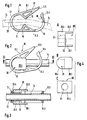
- Fig. 1 shows a central longitudinal section through the bracket-like clamp body 11 of the hose clamp 10, which is already prior art.
- the clamp body 11 has a first through-opening 12 and a second through-opening 13 for a hose 14 to be clamped, which is indicated in FIG. 1 with dash-dotted lines.
- a wedge-like jaw 15 or 16 is formed on each of the two bracket legs 11.1 and 11.2 of the clamp body 11, which jaws are moved against each other and clamp the hose 14 when the ends 11.3 and 11.4 of the two bracket legs 11.1 and 11.2 are moved towards each other to close the bracket-shaped clamp body 11.
- the end 11.3 of the bracket leg 11.1 is designed as a latching tongue.
- a latching step 18 is formed on the inside, into which the end 11.3 of the other stirrup leg 11.1 can snap into place.
- the stirrup legs are closed to form a closed annular clamp body 11 in a known manner by finger pressure on an outer corrugated surface 17 of the stirrup leg 11.1.
- the hose clamp 10 is opened by finger pressure in the outward direction on the end 11.4 of the other bracket leg 11.2.
- FIG. 2 shows the hose clamp 10 in a side view with a clipped-in insert body 20.
- the insert body 20 is shown individually in three views in FIG. 4. From Fig. 4 and the sectional view of Fig. 3 it can be seen that the insert body 20 is U-shaped and its two U-legs form thin side walls 20.1 and 20.2, which the laterally open clamp body 11 from its connecting area carrying the through opening 12 between cover the two stirrup legs 11.1 and 11.2 up to the two clamping jaws 15 and 16 and a little more.
- the U-base 20.3 of the insert body 20 is substantially stronger than the two side walls 20.1 and 20.2 and is provided with a through opening 21, the longitudinal axis of which runs parallel to the two side walls 20.1, 20.2.
- the rear end 20.4 of the insert body 20 is rounded and thus adapted to the connecting bend of the clamp body 11 in the area of the through opening 12.
Abstract
Description
Die Erfindung betrifft eine Schlauchklemme für medizinische Zwecke mit einem bügelartigen an den Bügelenden zu einem geschlossenen Ring rastverbindbaren Klemmenkörper, der Öffnungen für einen in der Bügelebene verlaufenden Durchgangskanal für den abzuklemmenden Schlauch und an beiden Bügelschenkeln je eine nach innen gerichtete, keilförmige Klemmbacke aufweist. Schlauchklemmen der genannten Art werden von der Anmelderin bereits vertrieben. Sie haben seitlich offene Klemmenkörper, so daß der Schlauch an der Klemmstelle von außen sichtbar bleibt. Dabei besteht aber die Gefahr daß sich ein sehr weicher und entsprechend flexibler Schlauch aus dem Klemmenkörper seitlich aus der Bügelebene ausbiegt mit der Folge, daß beim Schließen der Schlauchklemme die Klemmbacken den Schlauch nicht mehr oder nur noch teilweise erfassen.The invention relates to a hose clamp for medical purposes with a clamp-like clamp body which can be latched at the ends of the clamp to form a closed ring, which has openings for a through-channel running in the clamp plane for the hose to be clamped and on both clamp legs each has an inwardly directed, wedge-shaped clamping jaw. Hose clamps of the type mentioned are already sold by the applicant. They have clamp bodies that are open on the side so that the hose remains visible from the outside at the clamping point. However, there is a risk that a very soft and correspondingly flexible hose bends laterally out of the clamp plane from the clamp body, with the result that when the hose clamp is closed, the clamping jaws no longer or only partially grasp the hose.
Diese Gefahr ist besonders groß, wenn die Schlauchklemme an Krümmungsstellen eines Schlauches angesetzt werden muß.This risk is particularly great if the hose clamp has to be attached to the points of curvature of a hose.
Der Erfindung liegt die Aufgabe zugrunde, eine Schlauchklemme der eingangs genannten Art so auszubilden, daß mit ihr auch in Krümmungsbereichen eines Schlauches ein sicheres Erfassen des Schlauches durch die Klemmbacken gewährleistet ist.The invention is based on the object of designing a hose clamp of the type mentioned at the outset in such a way that a secure gripping of the hose by the clamping jaws is ensured with it, even in regions of curvature of a hose.
Die gestellte Aufgabe wird mit der eingangs genannten Schlauchklemme erfindungsgemäß dadurch gelöst, daß die Schlauchklemme zu beiden Seiten des Durchgangskanales parallel zu der Bügelebene gerichtete Seitenwandungen aufweist, die in der Schlauchklemme ein Auswölben des Schlauches aus der Bügelebene verhindern. Vorteilhafterweise können die Seitenwandungen dabei so bemessen sein, daß sie beide Klemmbacken mindestens teilweise seitlich abdecken.The stated object is achieved according to the invention with the hose clamp mentioned at the outset in that the hose clamp has side walls which are directed parallel to the bow plane on both sides of the through-channel and prevent the hose from bulging out of the bow plane in the hose clamp. Advantageously, the side walls can be dimensioned so that they cover both jaws at least partially on the side.
Durch die Seitenwandungen wird der Schlauch in unmittelbarer Nahe der Klemmbacken mit Sicherheit daran gehindert, aus der Ebene des seitlich offenen Klemmenkörpers auszubrechen Die Seitenwandungen können an den Klemmenkörper angeformt sein. Bei einer bevorzugten Ausführungsform sind die Seitenwandungen an einem gesonderten Einsatzkörper für den Klemmenkörper ausgebildet. Dies hat den Vorteil, daß kompliziertere Spritzgußformen für die aus Kunststoff hergestellten Klemmenkörper vermieden werden und daß die Schlauchklemmen wahlweise mit oder ohne die Einsatzkörper eingesetzt werden können. Bei relativ steifen Schläuchen kann nämlich auf die Seitenwandungen wie bisher verzichtet werden, und der Einsatzkörper kann auswechselbar im Klemmenkörper angeordnet sein.The side walls certainly prevent the hose in the immediate vicinity of the clamping jaws from breaking out of the plane of the laterally open terminal body. The side walls can be molded onto the terminal body. In a preferred embodiment, the side walls are formed on a separate insert body for the terminal body. This has the advantage that more complicated injection molds for the clamp bodies made of plastic are avoided and that the hose clamps can be used either with or without the insert bodies. With relatively rigid hoses, the side walls can be dispensed with as before be, and the insert body can be arranged interchangeably in the terminal body.
Der ebenfalls mit einfachen Spritzgußformen herstellbare Einsatzkörper kann vorteilhafterweise U-förmig sein, wobei die U-Schenkel die Seitenwandungen bilden, und in der U-Basis kann eine Schlauchdurchgangsöffnung mit parallel zu den Seitenwandungen gerichteter Öffnungsachse ausgebildet sein. Zweckmäßig kann die U-Basis des Einsatskörpers dicker als die Seitenwandungen ausgebildet sein, deren gegenseitiger freier Abstand mindestens der Dicke des Klemmenkörpers an der Einsatzstelle entspricht. Durch die Seitenwandungen wird die Dicke des Klemmenkörpers nur geringfügig erhöht, und die Seitenwandungen bilden glatte Abschlußflächen, die bei einem Aufliegen der Schlauchklemme auf der Haut eines Patienten keine unangenehmen Druck- und Scheuerstellen auf der Haut bilden können. Der Einsatzkörper läßt sich durch einfaches Aufweiten der Bügelschenkel in den Raum zwischen den beiden miteinander zusammenwirkenden Klemmbacken und dem Verbindungsbogen der Bügelschenkel einklipsen und zum Auswechseln auch wieder ausklipsen. In seiner Einsatzlage fluchtet die Schlauchdurchgangsöffnung des Einsatzkörpers mit einer Durchgangskanalöffnung für den abzuklemmenden Schlauch in dem Verbindungsbogen des Klemmenkörpers.The insert body, which can also be produced with simple injection molds, can advantageously be U-shaped, the U-legs forming the side walls, and a tube passage opening with an opening axis directed parallel to the side walls can be formed in the U-base. The U-base of the insert body can expediently be made thicker than the side walls, the mutual free spacing of which corresponds at least to the thickness of the clamp body at the point of use. The thickness of the clamp body is increased only slightly by the side walls, and the side walls form smooth end faces which, when the hose clamp rests on the skin of a patient, cannot form any uncomfortable pressure and abrasion points on the skin. The insert body can be clipped in by simply widening the stirrup legs into the space between the two interacting clamping jaws and the connecting bow of the stirrup legs and also clipped out for replacement. In its position of use, the hose passage opening of the insert body is aligned with a passage channel opening for the hose to be clamped in the connecting bend of the clamp body.
Nachfolgend wird ein Ausführungsbeispiel einer bevorzugten Ausführungsform der Schlauchklemme anhand der beigefügten Zeichnung näher erläutert.An exemplary embodiment of a preferred embodiment of the hose clamp is explained in more detail with reference to the accompanying drawing.
Im einzelnen zeigen:
- Fig. 1
- einen zentralen Längsschnitt durch den Klemmenkörper der Schlauchklemme;
- Fig. 2
- eine Seitenansicht der Schlauchklemme mit in den Klemmenkörper eingeklipstem Einsatzkörper;
- Fig. 3
- einen Schnitt durch die Schlauchklemme entlang der Linie III-III in Fig. 2;
- Fig. 4
- eine Einzeldarstellung des Einsatzkörpers der Schlauchklemme in einer Aufsicht A, einer Seitenansicht B und einer stirnseitigen Ansicht C.
- Fig. 1
- a central longitudinal section through the clamp body of the hose clamp;
- Fig. 2
- a side view of the hose clamp with the insert body clipped into the clamp body;
- Fig. 3
- a section through the hose clamp along the line III-III in Fig. 2;
- Fig. 4
- an individual representation of the insert body of the hose clamp in a top view A, a side view B and an end view C.
Fig. 1 zeigt einen zentralen Längsschnitt durch den bügelartigen Klemmenkörper 11 der Schlauchklemme 10, der bereits Stand der Technik ist. Der Klemmenkörper 11 weist eine erste Durchgangsöffnung 12 und eine zweite Durchgangsöffnung 13 für einen abzuklemmenden Schlauch 14 auf, der in Fig. 1 mit strichpunktierten Linien angedeutet ist. An den beiden Bügelschenkeln 11.1 und 11.2 des Klemmenkörpers 11 ist jeweils eine keilartige Klemmbacke 15 oder 16 angeformt, die gegeneinanderbewegt werden und den Schlauch 14 abklemmen, wenn die Enden 11.3 und 11.4 der beiden Bügelschenkel 11.1 und 11.2 zum Schließen des bügelförmigen Klemmenkörpers 11 gegeneinanderbewegt werden. Das Ende 11.3 des Bügelschenkels 11.1 ist als Rastzunge ausgebildet. An dem Ende 11.4 des anderen Bügelschenkels 11.2 ist innenseitig eine Raststufe 18 ausgebildet, in welche das Ende 11.3 des anderen Bügelschenkels 11.1 einrasten kann. Das Schließen der Bügelschenkel zu einem geschlossenen ringförmigen Klemmenkörper 11 erfolgt in bekannter Weise durch Fingerdruck auf eine Außenriffelfläche 17 des Bügelschenkels 11.1. Das Öffnen der Schlauchklemme 10 erfolgt durch Fingerdruck in Auswärtsrichtung auf das Ende 11.4 des anderen Bügelschenkels 11.2.Fig. 1 shows a central longitudinal section through the bracket-
Fig. 2 zeigt die Schlauchklemme 10 in Seitenansicht mit einem eingeklipsten Einsatzkörper 20. Der Einsatzkörper 20 ist in Fig. 4 einzeln in drei Ansichten dargestellt. Aus Fig. 4 und der Schnittdarstellung der Fig. 3 ist ersichtlich, daß der Einsatzkörper 20 U-förmig ausgebildet ist und seine beiden U-Schenkel dünne Seitenwandungen 20.1 und 20.2 bilden, welche den seitlich offenen Klemmenkörper 11 von seinem die Durchgangsöffnung 12 tragenden Verbindungsbereich zwischen den beiden Bügelschenkeln 11.1 und 11.2 bis zu den beiden Klemmbacken 15 und 16 und noch etwas darüber hinaus abdecken. Die U-Basis 20.3 des Einsatzkörpers 20 ist wesentlich stärker als die beiden Seitenwandungen 20.1 und 20.2 ausgebildet und mit einer Durchgangsöffnung 21 versehen, deren Längsachse parallel zu den beiden Seitenwandungen 20.1, 20.2 verläuft. Das rückseitige Ende 20.4 des Einsatzkörpers 20 ist abgerundet und damit an den Verbindungsbogen des Klemmenkörpers 11 im Bereich der Durchgangsöffnung 12 angepaßt. Durch Aufweiten der beiden Bügelschenkel 11.1 und 11.2 läßt sich der Einsatzkörper 20 zwischen den beiden Klemmbacken 15 und 16 hindurch in den Klemmenkörper 11 einklipsen.FIG. 2 shows the
Claims (7)
Applications Claiming Priority (2)
| Application Number | Priority Date | Filing Date | Title |
|---|---|---|---|
| DE4118732A DE4118732A1 (en) | 1991-06-07 | 1991-06-07 | HOSE CLAMP FOR MEDICAL PURPOSES |
| DE4118732 | 1991-06-07 |
Publications (3)
| Publication Number | Publication Date |
|---|---|
| EP0517000A2 true EP0517000A2 (en) | 1992-12-09 |
| EP0517000A3 EP0517000A3 (en) | 1993-02-03 |
| EP0517000B1 EP0517000B1 (en) | 1995-10-11 |
Family
ID=6433404
Family Applications (1)
| Application Number | Title | Priority Date | Filing Date |
|---|---|---|---|
| EP92107846A Expired - Lifetime EP0517000B1 (en) | 1991-06-07 | 1992-05-08 | Hose clamp for medical use |
Country Status (5)
| Country | Link |
|---|---|
| US (1) | US5203056A (en) |
| EP (1) | EP0517000B1 (en) |
| JP (1) | JPH0757243B2 (en) |
| AT (1) | ATE129054T1 (en) |
| DE (2) | DE4118732A1 (en) |
Cited By (22)
| Publication number | Priority date | Publication date | Assignee | Title |
|---|---|---|---|---|
| EP0637456A1 (en) * | 1993-07-09 | 1995-02-08 | SPANG & BRANDS GmbH | Tubing clamp |
| WO2008002961A2 (en) * | 2006-06-29 | 2008-01-03 | Vidacare Corporation | Apparatus and methods to harvest bone and bone marrow |
| WO2010062637A1 (en) * | 2008-10-28 | 2010-06-03 | Medical Components, Inc. | Clamp for flexible tubing |
| DE202009010388U1 (en) * | 2009-07-31 | 2010-12-09 | Düring, Klaus, Dr. | Fixation device for fixing an apnea stent in the airway |
| US9393031B2 (en) | 2002-05-31 | 2016-07-19 | Vidacare LLC | Apparatus and method to provide emergency access to bone marrow |
| US9439667B2 (en) | 2002-05-31 | 2016-09-13 | Vidacare LLC | Apparatus and methods to install, support and/or monitor performance of intraosseous devices |
| US9717847B2 (en) | 2002-05-31 | 2017-08-01 | Teleflex Medical Devices S.Àr.L. | Apparatus and method to inject fluids into bone marrow and other target sites |
| US9717564B2 (en) | 2002-05-31 | 2017-08-01 | Teleflex Medical Devices S.À R.L. | Biopsy devices and related methods |
| US9872703B2 (en) | 2002-05-31 | 2018-01-23 | Teleflex Medical Devices S.Àr.L. | Vascular access kits and methods |
| US10052111B2 (en) | 2003-05-30 | 2018-08-21 | Teleflex Medical Devices S.À R.L. | Powered driver |
| DE102017212883A1 (en) | 2017-07-26 | 2019-01-31 | B. Braun Melsungen Ag | Hose clamp for clamping a medical hose |
| US10245010B2 (en) | 2002-05-31 | 2019-04-02 | Teleflex Medical Devices S.A.R.L | Assembly for coupling powered driver with intraosseous device |
| US10258783B2 (en) | 2006-10-30 | 2019-04-16 | Teleflex Medical Devices S.À R.L. | Apparatus and methods to communicate fluids and/or support intraosseous devices |
| US10492830B2 (en) | 2002-05-31 | 2019-12-03 | Teleflex Medical Devices S.À R.L. | Penetrator assembly for accessing bone marrow |
| US10512474B2 (en) | 2002-05-31 | 2019-12-24 | Teleflex Medical Devices S.À R.L. | Powered drivers, intraosseous devices and methods to access bone marrow |
| US10595896B2 (en) | 2002-05-31 | 2020-03-24 | Teleflex Life Sciences Limited | Apparatus for accessing bone marrow including depth control mechanism |
| US10973532B2 (en) | 2002-05-31 | 2021-04-13 | Teleflex Life Sciences Limited | Powered drivers, intraosseous devices and methods to access bone marrow |
| US11103282B1 (en) | 2002-05-31 | 2021-08-31 | Teleflex Life Sciences Limited | Powered drivers, intraosseous devices and methods to access bone marrow |
| US11266441B2 (en) | 2002-05-31 | 2022-03-08 | Teleflex Life Sciences Limited | Penetrator assembly for accessing bone marrow |
| US11298202B2 (en) | 2002-05-31 | 2022-04-12 | Teleflex Life Sciences Limited | Biopsy devices and related methods |
| US11337728B2 (en) | 2002-05-31 | 2022-05-24 | Teleflex Life Sciences Limited | Powered drivers, intraosseous devices and methods to access bone marrow |
| US11426249B2 (en) | 2006-09-12 | 2022-08-30 | Teleflex Life Sciences Limited | Vertebral access system and methods |
Families Citing this family (67)
| Publication number | Priority date | Publication date | Assignee | Title |
|---|---|---|---|---|
| US5593392A (en) * | 1992-09-23 | 1997-01-14 | Starchevich; Jovanka | Intravenous flow regulating and mounting assembly |
| US5429615A (en) * | 1992-09-23 | 1995-07-04 | Starchevich; Jovanka | Intravenous flow regulating and mounting assembly |
| JP3653904B2 (en) * | 1996-12-09 | 2005-06-02 | 株式会社ジェイ・エム・エス | Tube open / close clamp |
| US6003742A (en) * | 1997-12-30 | 1999-12-21 | Garcia; Daniel R. | Spigot actuating device |
| EP0995461B1 (en) * | 1998-10-22 | 2004-09-22 | Industrie Borla SpA | Clamp for closing flexible hoses of infusion, transfusion and the like medical equipment |
| USD431650S (en) * | 1998-10-22 | 2000-10-03 | Industrie Borla S.P.A. | Clamp for closing flexible hoses of infusion, transfusion medical equipment |
| ES2227794T3 (en) * | 1998-10-22 | 2005-04-01 | Industrie Borla Spa | CLAMPING ELEMENT TO CLOSE FLEXIBLE HOSE OF INFUSION, TRANSFUSION AND SIMILAR MEDICAL EQUIPMENT. |
| IL127029A (en) | 1998-11-12 | 2002-03-10 | Medivice Systems Ltd | Pinch clamp |
| USD427307S (en) * | 1999-01-08 | 2000-06-27 | Industrie Borla S.P.A. | Clamp for flexible medical hoses |
| US6113062A (en) * | 1999-01-28 | 2000-09-05 | Dsu Medical Corporation | Squeeze clamp |
| IT1310919B1 (en) * | 1999-06-10 | 2002-02-27 | Enrico Balbo | QUICK PLACING CLAMP FOR FLOW RATE ADJUSTMENT FLEXIBLE HOSES, IN PARTICULAR FOR MEDICAL USE. |
| US8323228B2 (en) * | 2007-04-12 | 2012-12-04 | Rex Medical L.P. | Dialysis catheter |
| AU2002347812A1 (en) | 2001-10-05 | 2003-04-22 | Medical Components, Inc. | Catheter information ring |
| US20030139769A1 (en) * | 2002-01-18 | 2003-07-24 | Schrader Eugene F. | Roller milker device |
| US20030139768A1 (en) * | 2002-01-18 | 2003-07-24 | Schrader Eugene F. | Roller milker device |
| US20050215975A1 (en) * | 2002-01-31 | 2005-09-29 | Jean-Marie Mathias | Irreversibly closable flow control clamp |
| US8262639B2 (en) * | 2002-01-31 | 2012-09-11 | Fenwal, Inc. | Irreversible flow control clamp |
| WO2008033872A2 (en) * | 2006-09-12 | 2008-03-20 | Vidacare Corporation | Biopsy devices and related methods |
| WO2008033871A2 (en) * | 2006-09-12 | 2008-03-20 | Vidacare Corporation | Apparatus and methods for biopsy and aspiration of bone marrow |
| US8142365B2 (en) * | 2002-05-31 | 2012-03-27 | Vidacare Corporation | Apparatus and method for accessing the bone marrow of the sternum |
| US8690791B2 (en) | 2002-05-31 | 2014-04-08 | Vidacare Corporation | Apparatus and method to access the bone marrow |
| WO2008033873A2 (en) * | 2006-09-12 | 2008-03-20 | Vidacare Corporation | Medical procedures trays and related methods |
| US20040089828A1 (en) * | 2002-10-18 | 2004-05-13 | Werth Albert A. | Conduit clamp |
| US7712237B2 (en) * | 2002-11-26 | 2010-05-11 | Medron, Inc. | Clamp identification marker |
| DE10322007B3 (en) * | 2003-05-16 | 2004-07-15 | Daimlerchrysler Ag | Clamping bracket for hose has locking pin fitting in elongated hole in base to lock locking projection when clamping bar turns in |
| US7815642B2 (en) * | 2004-01-26 | 2010-10-19 | Vidacare Corporation | Impact-driven intraosseous needle |
| WO2006044827A2 (en) * | 2004-10-18 | 2006-04-27 | Z-Man Corporation | Pinch clamp |
| US8998848B2 (en) | 2004-11-12 | 2015-04-07 | Vidacare LLC | Intraosseous device and methods for accessing bone marrow in the sternum and other target areas |
| US7434779B2 (en) * | 2005-01-28 | 2008-10-14 | Twin Bay Medical, Inc. | Conduit clamp |
| AU2007233576B2 (en) * | 2006-04-05 | 2013-10-03 | Noble House Group Pty Ltd | Non-reopening locking pinch clamp for tubing |
| US7585547B2 (en) * | 2006-04-13 | 2009-09-08 | Solopower, Inc. | Method and apparatus to form thin layers of materials on a base |
| US7686279B2 (en) | 2006-05-12 | 2010-03-30 | Caridianbct, Inc. | Non-reopenable clamp for tubing sets |
| WO2008024440A1 (en) * | 2006-08-24 | 2008-02-28 | Medical Components, Inc. | Information clip for flexible tubing |
| US8025645B2 (en) * | 2007-05-25 | 2011-09-27 | Medical Components, Inc. | Guard for flexible tubing clamp and method of using same |
| US8328458B2 (en) * | 2007-07-20 | 2012-12-11 | Twin Bay Medical, Inc. | Sanitary clamp |
| US8328457B2 (en) * | 2007-07-20 | 2012-12-11 | Twin Bay Medical, Inc. | Sanitary clamp |
| JP2010125088A (en) * | 2008-11-28 | 2010-06-10 | Nippon Sherwood Medical Industries Ltd | Protective cover slip preventive means and endoscope set equipped with the same |
| US8377012B2 (en) * | 2009-01-30 | 2013-02-19 | Baxter International Inc. | Transfer sets for therapy optimization |
| US8973889B2 (en) * | 2009-03-13 | 2015-03-10 | Saint-Gobain Performance Plastics Corporation | Tube clamp |
| US9605782B2 (en) | 2009-04-02 | 2017-03-28 | Saint-Gobain Performance Plastics Corporation | Sanitary retainer |
| AU2009348770B2 (en) | 2009-06-25 | 2015-04-02 | Nestec S.A. | Pinch clamp assembly for an infusion cassette |
| US8430128B2 (en) * | 2009-11-10 | 2013-04-30 | Baxter International Inc. | Interlocking tubing clamps |
| WO2011097311A2 (en) | 2010-02-02 | 2011-08-11 | Vidacare Corporation | Intraosseous-needle stabilizer and methods |
| DE102010017216A1 (en) * | 2010-06-02 | 2011-12-08 | Technische Universität Berlin | Valve device for controlling a flow of a fluid through a fluid channel, arrangement and multi-way valve device |
| US8591450B2 (en) | 2010-06-07 | 2013-11-26 | Rex Medical L.P. | Dialysis catheter |
| US10143357B2 (en) * | 2010-08-10 | 2018-12-04 | Ronald Yamada | Endoscope gripping device |
| US9079008B2 (en) | 2011-02-17 | 2015-07-14 | Nipro Corporation | Medical tube clamp |
| WO2012157347A1 (en) * | 2011-05-16 | 2012-11-22 | テルモ株式会社 | Clamp and blood bag system |
| US9730729B2 (en) | 2011-07-11 | 2017-08-15 | Teleflex Medical Devices S.A R.L. | Sternal locators and associated systems and methods |
| US9050447B2 (en) * | 2011-11-23 | 2015-06-09 | Carefusion 303, Inc. | Positive bolus clamp |
| WO2013106605A1 (en) | 2012-01-11 | 2013-07-18 | Terumo Bct Biotechnologies, Llc | Slidable clamp for port isolation |
| CA2866155C (en) * | 2012-03-07 | 2017-07-25 | Springs Window Fashions, Llc | Hold down device for window covering looped operator |
| WO2014036325A2 (en) | 2012-08-30 | 2014-03-06 | C.R. Bard, Inc. | Tubing clamp |
| US9833606B2 (en) | 2012-09-07 | 2017-12-05 | Fenwal, Inc. | Non-reopenable flow control clamp |
| US8905978B2 (en) * | 2013-03-14 | 2014-12-09 | Haemonetics Corporation | Non-reopening tubing clamp and method of use thereof |
| JP6052030B2 (en) * | 2013-04-08 | 2016-12-27 | ニプロ株式会社 | Medical tube clamp |
| CN106659829B (en) | 2014-06-30 | 2020-03-03 | 日机装株式会社 | Clamping device for flexible pipe |
| CN107206227B (en) | 2015-02-03 | 2021-06-01 | 日机装株式会社 | Clamping device |
| JP6082433B2 (en) | 2015-06-22 | 2017-02-15 | 日機装株式会社 | Clamping device |
| US10384049B2 (en) | 2015-07-07 | 2019-08-20 | Halkey-Roberts Corporation | Tubing clamp |
| US11040186B2 (en) * | 2015-10-28 | 2021-06-22 | Becton, Dickinson And Company | Pinch clamp device |
| JP6706914B2 (en) | 2015-12-22 | 2020-06-10 | 日機装株式会社 | Clamp device |
| US10589082B2 (en) | 2016-02-17 | 2020-03-17 | Becton, Dickinson And Company | Pinch clamp |
| USD984880S1 (en) * | 2020-11-06 | 2023-05-02 | Medical Components, Inc. | Clamp with indicator |
| DE102021207509A1 (en) | 2021-07-14 | 2023-01-19 | B.Braun Avitum Ag | Device for clamping and holding medical tubing |
| US11752309B2 (en) * | 2021-09-22 | 2023-09-12 | Mark Wayne LENOX | Catheter delivery guidewire clamp |
| DE102021213753A1 (en) | 2021-12-03 | 2023-06-07 | B. Braun Melsungen Aktiengesellschaft | Medical hose clamp |
Citations (7)
| Publication number | Priority date | Publication date | Assignee | Title |
|---|---|---|---|---|
| US1580649A (en) * | 1925-09-04 | 1926-04-13 | Geo J Kelly Inc | Tube clamp |
| US3822052A (en) * | 1973-04-02 | 1974-07-02 | Illinois Tool Works | Shut off clamp |
| US4053135A (en) * | 1976-09-20 | 1977-10-11 | Sigma Scientific Development, Inc. | Hose clamp |
| US4097020A (en) * | 1977-05-05 | 1978-06-27 | Howard Sussman | Plant-watering device |
| FR2440512A1 (en) * | 1978-10-30 | 1980-05-30 | Plastronics Inc | FLEXIBLE TUBE CLAMPING DEVICE |
| DE3003527A1 (en) * | 1979-02-01 | 1980-08-14 | Ronald L Voller | HOSE CLAMP |
| DE8812121U1 (en) * | 1988-09-26 | 1989-01-05 | Sueddeutsche Feinmechanik Gmbh, 6480 Waechtersbach, De |
Family Cites Families (14)
| Publication number | Priority date | Publication date | Assignee | Title |
|---|---|---|---|---|
| US3766925A (en) * | 1971-05-25 | 1973-10-23 | Eljay Hospital Prod Corp | Surgical clamp with cam-action lever |
| DE7809912U1 (en) * | 1978-04-04 | 1978-07-13 | B. Braun Melsungen Ag, 3508 Melsungen | CATHETER CLAMP |
| DE3039591A1 (en) * | 1980-10-21 | 1982-05-19 | Günter van Dr.med. 4000 Düsseldorf Endert | ADAPTER |
| DE3041641A1 (en) * | 1980-11-05 | 1982-06-09 | Günter van Dr.med. 4000 Düsseldorf Endert | DEVICE FOR PRODUCING A HOSE CONNECTION |
| US4346869A (en) * | 1981-03-12 | 1982-08-31 | Macneill Robert L | Tube clamp |
| US4453295A (en) * | 1981-06-17 | 1984-06-12 | Solco Basel Ag | Device for pinching-off hoses |
| US4643389A (en) * | 1984-12-27 | 1987-02-17 | American Hospital Supply Corporation | Tubing occlusion clip |
| US4589626A (en) * | 1985-03-13 | 1986-05-20 | Bioresearch Inc. | Hose clamp |
| US4673161A (en) * | 1985-03-27 | 1987-06-16 | Sherwood Medical Company | Tube clamping device |
| US4725037A (en) * | 1987-04-06 | 1988-02-16 | Marvin Adelberg | Shut-off mechanism for clamp for regulating flow through plastic tubing |
| US4944485A (en) * | 1989-08-28 | 1990-07-31 | Ivac Corporation | Clamp for flexible tubing |
| US5035399A (en) * | 1990-05-25 | 1991-07-30 | C.R. Bard, Inc. | Protective tubing clamp apparatus |
| DE9011416U1 (en) * | 1990-08-06 | 1990-10-18 | Joka Kathetertechnik Gmbh, 7450 Hechingen, De | |
| JP3018848U (en) * | 1995-04-27 | 1995-11-28 | 株式会社バイムス | Waist belt |
-
1991
- 1991-06-07 DE DE4118732A patent/DE4118732A1/en not_active Withdrawn
-
1992
- 1992-05-07 US US07/879,341 patent/US5203056A/en not_active Expired - Lifetime
- 1992-05-08 AT AT92107846T patent/ATE129054T1/en not_active IP Right Cessation
- 1992-05-08 DE DE59203952T patent/DE59203952C5/en not_active Expired - Lifetime
- 1992-05-08 EP EP92107846A patent/EP0517000B1/en not_active Expired - Lifetime
- 1992-05-28 JP JP4178797A patent/JPH0757243B2/en not_active Expired - Lifetime
Patent Citations (7)
| Publication number | Priority date | Publication date | Assignee | Title |
|---|---|---|---|---|
| US1580649A (en) * | 1925-09-04 | 1926-04-13 | Geo J Kelly Inc | Tube clamp |
| US3822052A (en) * | 1973-04-02 | 1974-07-02 | Illinois Tool Works | Shut off clamp |
| US4053135A (en) * | 1976-09-20 | 1977-10-11 | Sigma Scientific Development, Inc. | Hose clamp |
| US4097020A (en) * | 1977-05-05 | 1978-06-27 | Howard Sussman | Plant-watering device |
| FR2440512A1 (en) * | 1978-10-30 | 1980-05-30 | Plastronics Inc | FLEXIBLE TUBE CLAMPING DEVICE |
| DE3003527A1 (en) * | 1979-02-01 | 1980-08-14 | Ronald L Voller | HOSE CLAMP |
| DE8812121U1 (en) * | 1988-09-26 | 1989-01-05 | Sueddeutsche Feinmechanik Gmbh, 6480 Waechtersbach, De |
Cited By (38)
| Publication number | Priority date | Publication date | Assignee | Title |
|---|---|---|---|---|
| EP0637456A1 (en) * | 1993-07-09 | 1995-02-08 | SPANG & BRANDS GmbH | Tubing clamp |
| US10413282B2 (en) | 2002-05-31 | 2019-09-17 | Teleflex Medical Devices S.Àr.L. | Apparatus and methods to harvest bone and bone marrow |
| US11234683B2 (en) | 2002-05-31 | 2022-02-01 | Teleflex Life Sciences Limited | Assembly for coupling powered driver with intraosseous device |
| US10492830B2 (en) | 2002-05-31 | 2019-12-03 | Teleflex Medical Devices S.À R.L. | Penetrator assembly for accessing bone marrow |
| US10456149B2 (en) | 2002-05-31 | 2019-10-29 | Teleflex Medical Devices S.À R.L. | Apparatus and method to access bone marrow |
| US11337728B2 (en) | 2002-05-31 | 2022-05-24 | Teleflex Life Sciences Limited | Powered drivers, intraosseous devices and methods to access bone marrow |
| US7951089B2 (en) | 2002-05-31 | 2011-05-31 | Vidacare Corporation | Apparatus and methods to harvest bone and bone marrow |
| US9393031B2 (en) | 2002-05-31 | 2016-07-19 | Vidacare LLC | Apparatus and method to provide emergency access to bone marrow |
| US9439667B2 (en) | 2002-05-31 | 2016-09-13 | Vidacare LLC | Apparatus and methods to install, support and/or monitor performance of intraosseous devices |
| US9717847B2 (en) | 2002-05-31 | 2017-08-01 | Teleflex Medical Devices S.Àr.L. | Apparatus and method to inject fluids into bone marrow and other target sites |
| US9717564B2 (en) | 2002-05-31 | 2017-08-01 | Teleflex Medical Devices S.À R.L. | Biopsy devices and related methods |
| US9872703B2 (en) | 2002-05-31 | 2018-01-23 | Teleflex Medical Devices S.Àr.L. | Vascular access kits and methods |
| US10016217B2 (en) | 2002-05-31 | 2018-07-10 | Teleflex Medical Devices S.À.R.L. | Apparatus and methods to install, support and/or monitor performance of intraosseous devices |
| US11324521B2 (en) | 2002-05-31 | 2022-05-10 | Teleflex Life Sciences Limited | Apparatus and method to access bone marrow |
| US10166332B2 (en) | 2002-05-31 | 2019-01-01 | Teleflex Medical Devices S.À R.L. | Apparatus to inject fluids into bone marrow and other target sites |
| US11298202B2 (en) | 2002-05-31 | 2022-04-12 | Teleflex Life Sciences Limited | Biopsy devices and related methods |
| US10245010B2 (en) | 2002-05-31 | 2019-04-02 | Teleflex Medical Devices S.A.R.L | Assembly for coupling powered driver with intraosseous device |
| US11291472B2 (en) | 2002-05-31 | 2022-04-05 | Teleflex Life Sciences Limited | Powered drivers, intraosseous devices and methods to access bone marrow |
| US11266441B2 (en) | 2002-05-31 | 2022-03-08 | Teleflex Life Sciences Limited | Penetrator assembly for accessing bone marrow |
| US11103282B1 (en) | 2002-05-31 | 2021-08-31 | Teleflex Life Sciences Limited | Powered drivers, intraosseous devices and methods to access bone marrow |
| US11103281B2 (en) | 2002-05-31 | 2021-08-31 | Teleflex Life Sciences Limited | Apparatus and methods to install, support and/or monitor performance of intraosseous devices |
| US10595896B2 (en) | 2002-05-31 | 2020-03-24 | Teleflex Life Sciences Limited | Apparatus for accessing bone marrow including depth control mechanism |
| US10512474B2 (en) | 2002-05-31 | 2019-12-24 | Teleflex Medical Devices S.À R.L. | Powered drivers, intraosseous devices and methods to access bone marrow |
| US10806491B2 (en) | 2002-05-31 | 2020-10-20 | Teleflex Life Sciences Limited | Vascular access kits and methods |
| US10893875B2 (en) | 2002-05-31 | 2021-01-19 | Teleflex Life Sciences Limited | Apparatus to access bone marrow |
| US10973532B2 (en) | 2002-05-31 | 2021-04-13 | Teleflex Life Sciences Limited | Powered drivers, intraosseous devices and methods to access bone marrow |
| US11065382B2 (en) | 2002-05-31 | 2021-07-20 | Teleflex Life Sciences Limited | Apparatus to inject fluids into bone marrow and other target sites |
| US10052111B2 (en) | 2003-05-30 | 2018-08-21 | Teleflex Medical Devices S.À R.L. | Powered driver |
| WO2008002961A3 (en) * | 2006-06-29 | 2008-05-15 | Vidacare Corp | Apparatus and methods to harvest bone and bone marrow |
| WO2008002961A2 (en) * | 2006-06-29 | 2008-01-03 | Vidacare Corporation | Apparatus and methods to harvest bone and bone marrow |
| US11426249B2 (en) | 2006-09-12 | 2022-08-30 | Teleflex Life Sciences Limited | Vertebral access system and methods |
| US11583668B2 (en) | 2006-10-30 | 2023-02-21 | Teleflex Life Sciences Limited | Apparatus and methods to communicate fluids and/or support intraosseous devices |
| US10258783B2 (en) | 2006-10-30 | 2019-04-16 | Teleflex Medical Devices S.À R.L. | Apparatus and methods to communicate fluids and/or support intraosseous devices |
| US11771439B2 (en) | 2007-04-04 | 2023-10-03 | Teleflex Life Sciences Limited | Powered driver |
| WO2010062637A1 (en) * | 2008-10-28 | 2010-06-03 | Medical Components, Inc. | Clamp for flexible tubing |
| DE202009010388U1 (en) * | 2009-07-31 | 2010-12-09 | Düring, Klaus, Dr. | Fixation device for fixing an apnea stent in the airway |
| WO2011012320A2 (en) | 2009-07-31 | 2011-02-03 | Duering Klaus | Fixing device for fixing an apnea stent in an airway |
| DE102017212883A1 (en) | 2017-07-26 | 2019-01-31 | B. Braun Melsungen Ag | Hose clamp for clamping a medical hose |
Also Published As
| Publication number | Publication date |
|---|---|
| DE59203952D1 (en) | 1995-11-16 |
| JPH05329210A (en) | 1993-12-14 |
| JPH0757243B2 (en) | 1995-06-21 |
| EP0517000B1 (en) | 1995-10-11 |
| EP0517000A3 (en) | 1993-02-03 |
| US5203056A (en) | 1993-04-20 |
| DE4118732A1 (en) | 1992-12-10 |
| DE59203952C5 (en) | 2007-05-03 |
| ATE129054T1 (en) | 1995-10-15 |
Similar Documents
| Publication | Publication Date | Title |
|---|---|---|
| EP0517000B1 (en) | Hose clamp for medical use | |
| DE3302707C2 (en) | ||
| DE60016562T2 (en) | PRESSURE TERMINAL | |
| DE19858581C2 (en) | Vascular clip | |
| DE1280468B (en) | Vascular clamp | |
| EP0444298A1 (en) | Working pliers | |
| CH634131A5 (en) | PLASTIC CLAMP. | |
| DE2932979A1 (en) | CLAMPING DEVICE | |
| CH648476A5 (en) | HAEMOSTATIC CLAMP AND DEVICE FOR ATTACHING THE SAME. | |
| DE2409494A1 (en) | CLIP FOR HANGING LAUNDRY AND SHEET-SHAPED PARTS ON A LINE | |
| DE4424046C2 (en) | Spring band clamp | |
| DE3642958B4 (en) | One-piece molded clamp | |
| DE2923893A1 (en) | HANGING CLAMP FOR INSULATED LADDERS AND LADDER BAND | |
| DE3039551C2 (en) | Bendable endoscope tubing assembly | |
| CH679736A5 (en) | ||
| DE2261684B2 (en) | Medical clamp | |
| DE2756818A1 (en) | ONE-PIECE HANGER FOR CONTAINER | |
| DE2300980C3 (en) | Locking clip | |
| DE2952618C2 (en) | Hemostatic forceps for microsurgical purposes | |
| DE2505716C3 (en) | Line-up mechanism for files or the like | |
| DE60214460T2 (en) | Pipe mounting clamp | |
| DE60108251T2 (en) | QUICK CONNECTOR | |
| DE2547875A1 (en) | Clamp for bag or tube for ileostomy patient - comprises rod with widened flat top within channel like tube | |
| DE4327064C3 (en) | Plastic clip made of two parts | |
| DE3624383A1 (en) | Clamp for fixedly clamping a hose |
Legal Events
| Date | Code | Title | Description |
|---|---|---|---|
| PUAI | Public reference made under article 153(3) epc to a published international application that has entered the european phase |
Free format text: ORIGINAL CODE: 0009012 |
|
| AK | Designated contracting states |
Kind code of ref document: A2 Designated state(s): AT BE CH DE DK ES FR GB GR IT LI NL SE |
|
| PUAL | Search report despatched |
Free format text: ORIGINAL CODE: 0009013 |
|
| AK | Designated contracting states |
Kind code of ref document: A3 Designated state(s): AT BE CH DE DK ES FR GB GR IT LI NL SE |
|
| 17P | Request for examination filed |
Effective date: 19930729 |
|
| 17Q | First examination report despatched |
Effective date: 19950221 |
|
| GRAA | (expected) grant |
Free format text: ORIGINAL CODE: 0009210 |
|
| AK | Designated contracting states |
Kind code of ref document: B1 Designated state(s): AT BE CH DE DK ES FR GB GR IT LI NL SE |
|
| PG25 | Lapsed in a contracting state [announced via postgrant information from national office to epo] |
Ref country code: DK Effective date: 19951011 Ref country code: NL Free format text: LAPSE BECAUSE OF FAILURE TO SUBMIT A TRANSLATION OF THE DESCRIPTION OR TO PAY THE FEE WITHIN THE PRESCRIBED TIME-LIMIT Effective date: 19951011 Ref country code: ES Free format text: THE PATENT HAS BEEN ANNULLED BY A DECISION OF A NATIONAL AUTHORITY Effective date: 19951011 Ref country code: GR Free format text: LAPSE BECAUSE OF FAILURE TO SUBMIT A TRANSLATION OF THE DESCRIPTION OR TO PAY THE FEE WITHIN THE PRESCRIBED TIME-LIMIT Effective date: 19951011 Ref country code: BE Effective date: 19951011 |
|
| REF | Corresponds to: |
Ref document number: 129054 Country of ref document: AT Date of ref document: 19951015 Kind code of ref document: T |
|
| REF | Corresponds to: |
Ref document number: 59203952 Country of ref document: DE Date of ref document: 19951116 |
|
| ITF | It: translation for a ep patent filed |
Owner name: STUDIO APRA' BREVETTI |
|
| GBT | Gb: translation of ep patent filed (gb section 77(6)(a)/1977) |
Effective date: 19951117 |
|
| ET | Fr: translation filed | ||
| NLV1 | Nl: lapsed or annulled due to failure to fulfill the requirements of art. 29p and 29m of the patents act | ||
| PG25 | Lapsed in a contracting state [announced via postgrant information from national office to epo] |
Ref country code: AT Effective date: 19960508 |
|
| PG25 | Lapsed in a contracting state [announced via postgrant information from national office to epo] |
Ref country code: LI Effective date: 19960531 Ref country code: CH Effective date: 19960531 |
|
| PLBE | No opposition filed within time limit |
Free format text: ORIGINAL CODE: 0009261 |
|
| STAA | Information on the status of an ep patent application or granted ep patent |
Free format text: STATUS: NO OPPOSITION FILED WITHIN TIME LIMIT |
|
| 26N | No opposition filed | ||
| REG | Reference to a national code |
Ref country code: CH Ref legal event code: PL |
|
| REG | Reference to a national code |
Ref country code: GB Ref legal event code: IF02 |
|
| REG | Reference to a national code |
Ref country code: GB Ref legal event code: 732E |
|
| REG | Reference to a national code |
Ref country code: FR Ref legal event code: TP |
|
| REG | Reference to a national code |
Ref country code: FR Ref legal event code: CD |
|
| REG | Reference to a national code |
Ref country code: FR Ref legal event code: GC |
|
| REG | Reference to a national code |
Ref country code: GB Ref legal event code: 732E |
|
| PGFP | Annual fee paid to national office [announced via postgrant information from national office to epo] |
Ref country code: SE Payment date: 20110506 Year of fee payment: 20 Ref country code: FR Payment date: 20110511 Year of fee payment: 20 |
|
| PGFP | Annual fee paid to national office [announced via postgrant information from national office to epo] |
Ref country code: GB Payment date: 20110421 Year of fee payment: 20 |
|
| PGFP | Annual fee paid to national office [announced via postgrant information from national office to epo] |
Ref country code: DE Payment date: 20110531 Year of fee payment: 20 Ref country code: IT Payment date: 20110523 Year of fee payment: 20 |
|
| REG | Reference to a national code |
Ref country code: FR Ref legal event code: RG Effective date: 20120215 |
|
| REG | Reference to a national code |
Ref country code: DE Ref legal event code: R071 Ref document number: 59203952 Country of ref document: DE |
|
| REG | Reference to a national code |
Ref country code: DE Ref legal event code: R071 Ref document number: 59203952 Country of ref document: DE |
|
| REG | Reference to a national code |
Ref country code: GB Ref legal event code: PE20 Expiry date: 20120507 |
|
| REG | Reference to a national code |
Ref country code: SE Ref legal event code: EUG |
|
| PG25 | Lapsed in a contracting state [announced via postgrant information from national office to epo] |
Ref country code: DE Free format text: LAPSE BECAUSE OF EXPIRATION OF PROTECTION Effective date: 20120509 |
|
| PG25 | Lapsed in a contracting state [announced via postgrant information from national office to epo] |
Ref country code: GB Free format text: LAPSE BECAUSE OF EXPIRATION OF PROTECTION Effective date: 20120507 |